Featured Application
The paper provides an overview of the results of the experimental and simulative activities on a novel all-in-one adsorption thermal storage with zeolite. The results are a useful contribution to the knowledge about this new configuration.
Abstract
The paper discusses the performances of a novel all-in-one adsorption thermal storage based on steam vapour and zeolite 13X for industrial end-users. Steam production/condensation for the adsorption/desorption processes are executed within the same vacuum reactor, where the zeolite is heated and cooled by the thermal fluid which flows within a heat exchanger. Both experimental approach and numerical method are used to assess the behaviour and energy performances of the novel system. So, a medium-scale prototype was constructed and some experimental tests for the charging and discharging phases were carried out, producing useful data for the validation of a time-dependent model of the adsorption/desorption processes, which resulted very reliable in the simulation of the thermal storage system. The charging and discharging efficiency of thermal energy can reach values higher than 80% and 50%, respectively. The experimental campaign and the simulative activities highlighted some operative criticalities of the all-in-one thermal storage system and suggested some possible technical improvements to face and solve them.
1. Introduction
The use of solar energy for thermal applications can lead to significant reductions in the consumption of fossil fuels for both industrial and domestic use [1,2]. However, the variability of solar energy production represents a challenging issue [3].
The adoption of thermal storage can help to mitigate the daily solar power fluctuations, allowing to accumulate excessive energy during the peak production for later use [4]. In fact, storage allows to increase the efficiency of the solar systems, ensuring greater exploitation of this resource [5]. For this reason, many experimental and numerical studies were performed in the recent years with the aim of investigating the advantages of different thermal energy storage configurations for solar applications [6,7,8,9,10].
The three main technologies of thermal energy storage are: sensible, latent, and thermo-chemical heat storage.
The sensible heat storage is characterised by the temperature increment of a material compared to a reference temperature. This material can be both solid and liquid and generally, liquid water is used thanks to its low cost [11]. However, due to low energy density, heat losses and low-temperature operative range (50–100 °C), it is preferable to adopt sensible heat storage for domestic applications and without solar concentration [12].
In latent heat storage, solar heat is accumulated due to the phase change latent heat and generally, solid–liquid transition is adopted. Compared to sensible heat storage, it is possible to obtain higher energy density and lower temperature fluctuations [13,14]. Nevertheless, external heat losses, slow phase change kinetics and high specific volume variations limit the adoption of this technology [15].
Thermo-chemical heat storage is based on physical or chemical reversible reactions between two materials. This process involves solid–gas, liquid–gas and gas–gas reactions, which are characterised by very slow kinetics. The physical reaction, like absorption and adsorption, requires lower charging temperature compared to chemical ones and consequently, exhibits faster kinetics [16,17,18]. Moreover, typical temperature values are in the order of 50–200 °C, making these technologies a suitable choice for industrial applications.
In Reference [19], Demir et al. compared different adsorption heat pumps, underlying advantages and disadvantages of the different technologies. In Reference [20], Vasta et al. described the state-of-the-art of the adsorption heat storage, reporting the features for different adsorbent materials. In particular, zeolite and zeo-like materials characteristics are reported, underling the excellent compatibility with water vapour. Furthermore, the high energy density and operative temperature (i.e., more than 150 °C) promote the adoption of adsorption zeolite thermal storage for industrial applications together with the utilisation of concentrated solar power. Consequently, in the recent years, many studies focusing on vapour -zeolite adsorption thermal storage were performed.
In Reference [21], Schreiber et al. estimated heat losses of an experimental apparatus characterised by a closed unit thermal energy storage filled with 10 kg of zeolite 13X. They found high thermal efficiency (higher than 90%), both for charging and discharging phases. In Reference [22], Schreiber et al. developed a one-dimensional lumped-parameter model for the simulation of both short- and long-term energy storage of a zeolite adsorption thermal storage. In Reference [23], Yu et al. reported and described different configurations of sorption thermal storage for solar energy, highlighting the capabilities of zeolite as adsorbent material for long-term applications. In Reference [24], Weber et al. carried out an experimental and numerical analysis of a combined hot water and sorption store for solar applications using zeolite as adsorbent material.
The heat transfer between adsorbent bed and regenerating fluid is one of the most challenging issues to deal with for zeolite adsorption storage. In fact, the indirect contact between the adsorbent bed and the thermal fluid (HTF), together with the zeolite low thermal conductivity (in the range of 0.1–0.2 W/mK), lead to a deterioration of heat transfer capabilities and consequently to lower process efficiency and longer regeneration time [25]. For this reason, different heat exchanger geometries and adsorbent bed configurations were designed in the recent past [25]. The drawbacks are obviously the technological realisation and the high cost of such systems.
In this work, a novel all-in-one adsorption thermal storage based on steam vapour and 13X zeolite is presented and its performances are evaluated using both an experimental and modelling approach. The novel concept is characterised by simplicity of design and use, satisfying thermal storage performances. The innovative feature of this system is obtained thanks to a single configuration, where the steam condenser/evaporator for the desorption/adsorption of the zeolite are within the same reactor, filled with 13X zeolite spheres. The zeolite is heated and cooled by a U-tube finned heat exchanger, and hot water (up to 90 °C), together with ambient temperature water, are provided to the reactor in order to simulate the connection with a thermal solar system and an end-user.
The purpose of the paper is to demonstrate the validity of the energy performances of the novel adsorption thermal storage. Consequently, both experimental and numerical tests were performed using an in-house facility together with the Matlab code. The features of the prototype are studied, and particular attention is dedicated to thermal efficiency of the charging and discharging phases.
The structure of the paper is organised as follows. The experimental facility adopted is described in the first part of Section 2, while the Matlab mathematical model is analysed in the second part. In the following section, the experimental and numerical procedures are described. In Section 3, a description of the experiments performed is reported together with the obtained numerical and experimental results. Finally, Section 4 is dedicated to the general discussion of the outcomes, highlighting advantages of the novel all-in-one adsorption thermal storage. Possible improvements are proposed according to results obtained and future works are suggested.
2. Materials and Methods
2.1. The Experimental Facility
In the frame of the present paper, an experimental device able to reproduce performances of an adsorption storage system has been developed as well as a methodology for testing the process under long-term conditions.
The adsorption experimental plant works on 4 different temperature levels:
- Desorption heat is supplied by the heat source at temperature Tdes. Due to normative constraint, the maximum value of heat supply cannot overcome 90 °C.
- Condensation heat is released to the environment at a temperature Tcond. The condensation source can be set in a large range of 5–30 °C for experimental purposes.
- Adsorption heat is supplied to the final user at the temperature Tads in a large range of 5–30 °C.
- Evaporation heat is provided from a low temperature heat source in a range of 20–40 °C.
The experimental test rig has been designed taking into account the requirement of versatility (for testing different heat exchanger configurations or different plant configurations) and automatic control (for long-term test and data acquisition).
In order to validate the mathematical model of adsorption/desorption, a small-scale reactor has been designed and constructed. The concept idea of the novel configuration, so called “all-in-one”, is an embedded solution for both the heat exchanger module and phase changer module. This configuration involves a unique vacuum case with a considerable simplification of mechanical architecture and cost decrease. In Figure 1 and Figure 2, cross-sections of the experimental reactor are reported.
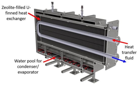
Figure 1.
Midplane cross-section of reactor “all-in-one” configuration.
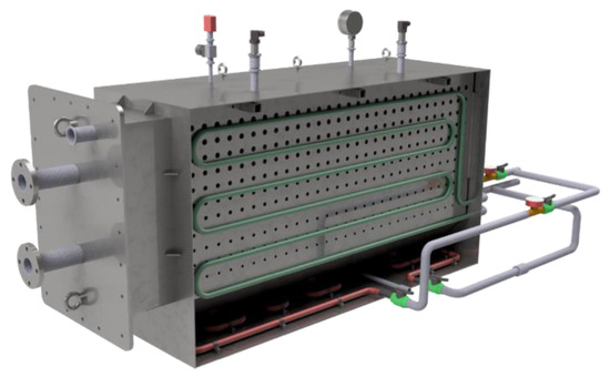
Figure 2.
Lateral cross-section of reactor “all-in-one” configuration.
The reactor is composed by:
- -
- Heat storage module (zeolite bed) with a total volume of 200 L, including a U-shaped heat exchanger with a finned tube (rectangular fin with 25 mm spacing). The lateral faces are realised with a metallic mesh able to retain zeolite 13X-grains, allowing vapour flow through the lateral faces. The zeolite bed is heated (during the desorption phase) and cooled (adsorption phase) by the thermal fluid (i.e., hot water) flowing into the finned tube.
- -
- Phase changing module placed at the bottom (water pool) and on two lateral faces (cold plates) with a tube coil which is cooled (during the condensation/desorption phase) and heated (during the evaporation/adsorption phase) through thermal fluid flowing into the coil tube.
Stainless-steel is used for all the metallic construction. The whole reactor has a removable mechanical system (with a bolt flange and vacuum sealing) in order to test different heat exchanger configurations or different evaporator/condenser technical designs. In Figure 3, the views of the zeolite bed and vacuum case are shown.
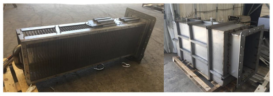
Figure 3.
Views of heat exchanger and vacuum chamber.
The whole reactor external casing has been insulated with a mineral insulation roll 50 mm thick with a thermal conductivity at ambient temperature equal to 0.039 W/(m K). The pad is faced on one side with aluminium kraft paper and on the other side with a glass mat. The overall estimated thermal losses are about 3.85 W/K and can be considered negligible in the modelling and experimental activities, discussed below.
The reactor has been instrumented with the following items:
- -
- 2 piezoelectric pressure sensors for vacuum chamber with an accuracy equal to 1.25 mbara.
- -
- 2 PT100 class A sensors for HTF Heat Exchanger temperature with accuracy at 0 and 100 °C, equal to ±0.15 °C and ±0.35 °C, respectively.
- -
- 2 PT100 class A sensors for HFT Evaporator/Condenser temperature, with accuracy at 0 and 100 °C, equal to ±0.15 °C and ±0.35 °C, respectively.
- -
- 1 visual pressure indicator for vacuum chamber.
- -
- 4 thermocouples, type K, for temperature bed acquisition with accuracy equal to ±1.1 °C (as shown in Figure 4).
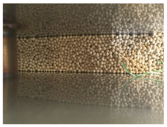 Figure 4. Thermocouple for temperature data acquisition within the zeolite bed.
The experimental facility for test purposes has been specifically designed and built. The adsorption reactor has been integrated in a hydraulic plant piping (AISI tubes). The plant consists of:
- Zeolite reactor with mechanical support,
- Heat pump chiller for cooling (condensation) source, with an electrical power of 10 kW,
- Electric heater (2 resistances for 10 kW total power) for heating (evaporation) purposes,
- 4 tanks with 300 L of capacity for thermal flow management,
- Vacuum dry-scroll pump,
- Metallic skid for whole system,
- Hydraulic pumps for HTF flows, flow meter with an accuracy equal to ±5% and electrical valve for plant operation.
In Figure 5, the experimental set-up is shown.
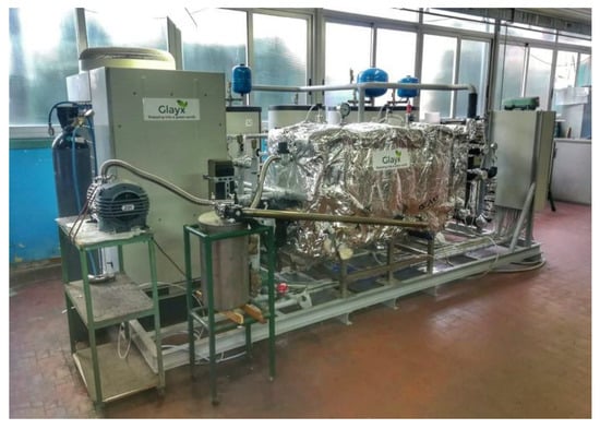
Figure 5.
Experimental set-up.
The plant is able to test the desorption/adsorption phase in different conditions: the internal pressure during the condensation/evaporation process is imposed through a strict control of temperature and mass flow of HTF inside the coil tube on lateral plates or in a water pool.
In order to start with the experimental phase, the whole reactor chamber is evacuated up to the target internal pressure through the vacuum pump and the internal pool is filled at the proper level. During the charge phase (desorption), the reactor is heated up with HTF at constant mass flow and inlet temperature (by automatic control of electric heater). After increasing due to initial desorption, the internal pressure is kept at a value as constant as possible acting on the condensation pool or plate through tuning the mass flow into the coil tubes. The thermal tanks (for reactor heating and vapour condensation) have been previously charged at the target temperature. All the parameters are registered for physical quantities’ evaluation. After a storage time, the discharge phase is carried out: the reactor is cooled down with HTF at constant mass flow and inlet temperature (by automatic control of chiller),and the evaporation and the vapour adsorption take place with a constant internal pressure, in the same way as during the condensation process.
The physical quantities to be evaluated are:
- Discharged Power (W):
- Stored Energy (Wh):where tads is the time duration of the adsorption process, HTF and cp are the mass flow and the specific isobaric heat capacity of HTF in the finned tube respectively, and Tout,HTF and Tin,HTF are the HTF temperatures at the reactor outlet and inlet section, respectively.
2.2. Mathematical Model
With reference to TES geometry (Figure 1), the reactor has been divided into identical portions (nodes), all having the same shape and connected in series. For each i-th node, a one-dimensional lumped parameter model has been implemented, in which the trends of the physical variables depend on time and longitudinal spatial dimension. Every node was then modelled through four sub-components, interacting with each other through energy and mass exchanges, represented by: the HTF, the finned heat-exchanger, the bed of zeolite and the water vapour enveloping the zeolite bed.
2.2.1. Energy Balance Equations
The model equations, describing the transient heat balances for each i-th node, are defined under the following conditions:
- The zeolite bed is modelled as a homogeneous porous medium, where the gas phase is constantly in thermal equilibrium with the solid phase.
- The water vapour is modelled as an ideal gas with temperature and pressure such as to be always below the saturation curve during the evolution of the process.
- Heat and mass transfer between solid and gas phases in the reactor are regulated by adsorption kinetics, whose equations are described in the following paragraph.
- The surrounding water vapour exchanges energy and mass with the zeolite bed through a steam flow entering or leaving the bed during the adsorption or desorption phase. This steam flow is continuously reintegrated by an evaporating or condensing flow coming from the pool below the reactor.
HTF energy balance:
where is the convective heat transfer coefficient given by according to Dittus-Boelter empirical correlation.
Heat-exchanger energy balance:
where is the heat capacity of heat-exchanger and zeolite, evaluated taking into account the conductive heat transfer and the effects of the fin.
Zeolite energy balance for adsorption (5) and desorption (6):
where the last two terms on the right side of both equations represent, respectively, the adsorption/desorption heat and the water vapour enthalpy entering (+ sign) or leaving (− sign) the zeolite bed. Similar to the previous equation, represents the heat capacity of zeolite bed and water vapour surrounding the zeolite reactor. Such parameter is estimated considering the natural convection heat transfer between the water vapour and the internal walls of the zeolite bed.
Surrounding water vapour energy balance during adsorption (7) and desorption (8) processes:
where and are respectively, the evaporating/condensing mass flow rate coming from (+ sign) or going to (− sign) the pool below the reactor. is the heat capacity of water vapour and the bath, also evaluated through an analysis of the heat exchanged in natural convection. Due to the high degree of insulation implemented, as stated in the previous paragraphs, the heat losses between the reactor and the environment has been neglected.
Finally, the following mass balance equations are stated:
where the first equation refers to the mass balance of the water vapour inside the zeolite bed, while the second one refers to the mass balance of the water vapour in the external area.
2.2.2. Kinetics and Equilibrium Models
In order to describe the adsorption rate of the water vapour on zeolite, a linear driving force (LDF) model has been implemented. This type of model is widely used for describing adsorption and desorption processes due to its analytical simplicity and physical consistency [26,27,28]. Its mathematical expression is the following:
where x and are, respectively, the adsorbed and equilibrium water loading per kg of dry zeolite, and is the kinetics coefficient depending on the bed temperature and the water vapour pressure, according to the following equation:
where is the macropore diffusivity which represents the dominant part of the mass transfer resistance of water vapour on zeolite [28].
The adsorption equilibrium is modelled using Langmuir–Freundlich isotherms, modified by the Aranovich and Donohue term [29], which takes into account the condensation effects occurring when water vapour approaches the saturation pressure. It can be expressed with the following equation:
where is the maximum amount of adsorbed water, k and d are system-dependent parameters, while b is a temperature-dependent parameter which can be described as follows:
where is the adsorption affinity and is the activation energy.
2.2.3. Model Implementation
Starting from equations from (3) to (11), a Matlab script [30], able to solve the set of ODEs both for adsorption and desorption process, has been implemented. In particular, for each i-th node, a state vector has been defined, whose components are the unknown variables to be calculated for each time instant. Therefore, the set of ODEs has been rewritten in the following matrix form: , where is the mass matrix and is a vector containing the terms of differential equations not dependent from the derivative. The solution of the ODEs systems depends on the initial state vector and inlet parameters (in general, time-dependent functions), which are represented by: the HTF temperature at the inlet of the i-th node, the HTF flow rate, the pool temperature and the water vapour pressure. By means of an iterative process, extended to the N nodes into which the reactor is divided, the parameters entering the node (i + 1) are updated with those leaving the previous node.
The model allows to determine the trends of the different variables along the longitudinal axis of the finned heat-exchanger, the heat exchanged between thermal energy storage and HTF, the thermal energy stored or released and the water uptake during the sorption/desorption process.
The above-mentioned set of ODEs apply only to the “all-in-one” reactor configuration, where the vapour is confined in the vacuum case that encloses the zeolite bed. However, the current configuration of the reactor allows also to investigate the desorption process of a typical thermochemical storage, where the vapour condensation is obtained in an external chamber (“phase changer” configuration). This can be achieved by keeping the water pool empty and extracting the water vapour through the vacuum pump. This operating condition involves a simplification of the mathematical model applied to the desorption process. Hence, Equation (8), related to the energy balance of the surrounding water vapor, becomes unessential and the term in Equation (6) is replaced by the convective heat transfer between the internal walls of the zeolite bed and the steam current produced by the vacuum pump. Since the condensing vapour flow is equivalent to the vapour flow exiting from the zeolite bed, the mass balance Equation (10) also becomes redundant. Therefore, the new ODEs system, describing the desorption process without pool, reduces to 5 equations with a state vector . The solution of this adjusted set of ODEs allows to investigate the effects of the vacuum pump for controlling the pressure inside the reaction chamber.
3. Results
3.1. The Experimental Tests
Using the test rig, a wide experimental campaign was carried out in order to assess the charging and discharging efficiency of the system for different operative conditions. The experimental data which were collected have been used for the following validation of the mathematical model.
The efficiency of charge and discharge phases is evaluated as follows:
where Qsens is the sensible heat that is stored/extracted from the zeolite, bath, stainless-steel case, and water adsorbed during the charge/discharge phase thanks to their temperature variation during the processes. Qdes and Qads are the thermochemical energy that is provided to and extracted from the zeolite for the desorption and adsorption processes. They are calculated as follows:
where xstart and xend are the water uptake (kg water/kg dry zeolite) at the start and end of each process, and mz is the mass of dry zeolite within the bed.
QHTF_c and QHTF_d are the energy that is transferred from/to the thermal fluid during the charging/discharging phases. Finally, QE/C is the thermal energy that is provided to the pool during the adsorption for the vapour production. This contributes to the energy input during the discharging phase. The energy provided to the cold water flowing through the pool and cool plates for the vapour condensation is not computed as a useful effect during the charging phase because its temperature is too low to assure a useful exploitation.
Table 1 reports the data and results of the tests that are presented in this paper. Considering the accuracy of the instruments for the measurement of HTF mass flow and temperatures, the accuracy of the estimation of the charge/discharge efficiency is about 5% with respect to the values which are reported in Table 1. No replications of the same tests were executed because it was very complex and unreliable to obtain the same starting conditions in terms of pressure and temperature field within the zeolite bed. Concerning the desorption, we tested both the possibility to use contemporarily (Test 1) the cooling plates and the pool for the vapour condensation, which is requested for the pressure control inside the vacuum chamber, and the use of the sole pool (Test 2). In this way, we investigated the effect of the cooling plates on the temperature trend of the zeolite bed. In Test 3, we investigated the effect of the vacuum pump for the vapour extraction from the chamber as a method for the vacuum control without using the cool plates and pool. The aim of this test is to obtain a benchmarking with the typical configuration of thermochemical storage with zeolite, where the vapour condensation and evaporation are obtained in a different chamber (phase changer configuration). During the discharging phase, when the stored energy is collected by the end-user, we compared the effectiveness of the pool heating for the vapour production, which is necessary for the zeolite adsorption. In Test 4, the pool is not heated, and the vacuum induced by the vapour adsorption assures the vapour evaporation from the pool. In Test 5, during the first 600 min, hot water periodically feeds the pool to produce the vapour required by the absorption and, consequently, to assure the maintained pressure of the vacuum chamber within the range 13–15 mbar. The charging and discharging efficiency of all these tests is reported in Table 1.

Table 1.
Data and results of the experimental tests.
Within the bed, four temperature thermocouples assure the measurement of the temperature profile of the zeolite. Figure 6 and Figure 7 show the trends of the mean value of these four measures during the desorption and adsorption tests, respectively. The test results can be commented as follows:
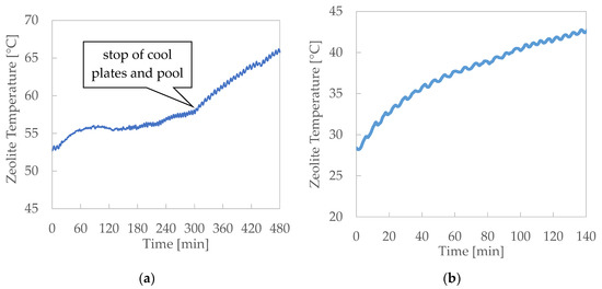
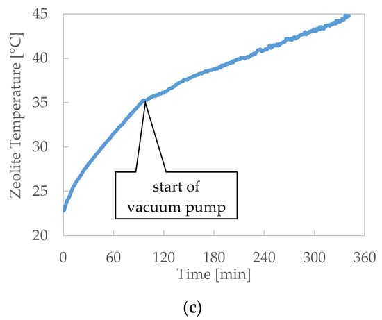
Figure 6.
Desorption results: zeolite temperatures during the test. (a) Desorption—Test 1, (b) Desorption—Test 2 and (c) Desorption—Test 3.
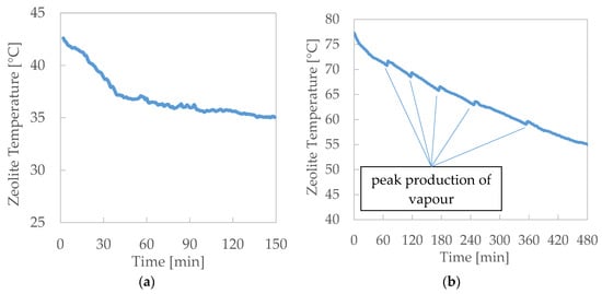
Figure 7.
Adsorption results: zeolite temperatures during the test. (a) Adsorption—Test 4 and (b) Adsorption—Test 5.
- -
- Notwithstanding, the heat exchange between the thermal fluid and the zeolite is promoted by the high finned surface of the heater, and the heat flux, equal to about 4 kW per m of bed width, resulted limited by the narrow thermal conductivity of the zeolite.
- -
- The charging efficiency that can be obtained using the cool plates for the vapour condensation is sensibly lower than the efficiency related to the case when the pool is the only cold sink.
- -
- When the flow of the cold water in the cool plates and pool is interrupted, the condensing capacity as heat sink of the only pool without forced cooling is not suitable to assure the right condensation of vapour to maintain the pressure constant.
- -
- When the vacuum pump is used to extract the vapour from the chamber and to maintain constant pressure, the zeolite temperature grows more slowly than when it is not present. Moreover, the use of the vacuum pump assures a higher uniformity of the temperature within the zeolite bed, maintaining a higher temperature of the external zeolite zone.
- -
- During the desorption, temperature time gradient roughly doubles when the cooling flow through the plates and pool is stopped.
- -
- During the adsorption, the instant production of vapour for zeolite adsorption evidently promotes a heat release by the zeolite that is not instantly absorbed by the HTF, with a consequent local peak of zeolite temperature.
- -
- The production of the vapour during the adsorption can also be obtained without the flow of hot thermal fluid through the pool. The vapour adsorption by the zeolite promotes the water evaporation from the pool, which progressively cools down. This fact produces an evident chilling effect which could be effectively exploited in combination with the thermal recovery by the thermal fluid. This configuration is consequently characterised by a higher discharge efficiency, because the thermal input of warm thermal fluid for the evaporation from the pool is null.
3.2. Model Results
Properties of the zeolite 13X and the operational conditions adopted for the simulation analysis are listed in Table 2. In all simulations, it was assumed that the zeolite reactor started from an equilibrium condition, where the initial temperature is given by the average of the temperatures detected by the 4 thermocouples immersed in the zeolite bed, while the vapour pressure is equal to that detected by the two piezoelectric sensors. From this, it follows that the initial state vector depends only on these two quantities, since it is possible to determine the water-uptake from the corresponding equilibrium isotherm (Equation (13)) and the masses of vapour inside and outside the zeolite bed from the respective state equations.
Table 2.
Properties of the zeolite 13X and process parameters.
In order to assess the effects of the inconstancy of the operative initial conditions on the reactor performance, a sensitivity analysis applied to the initial state vector was performed. The results show that a deviation within the expanded uncertainty (±1.3 °C) of the initial average bed temperature causes variations in the estimate of the adsorption/desorption heat between 3% and 5%, respectively. Similarly, a deviation within the expanded uncertainty (±1.4 mbar) of the measured initial reactor pressure produces variations in the energy output between 1% and 3%.
Figure 8 shows two examples of simulation outputs evaluated in the following conditions:
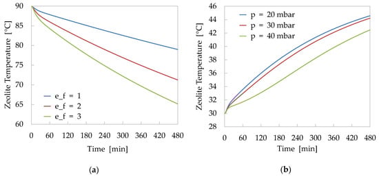
Figure 8.
Results of sensitivity analysis: (a) Effects of fin effectiveness on the temperature profile of zeolite bed during adsorption process (value of fin effectiveness equal to 1 corresponds to a not finned tube). (b) Effects of vapour pressure inside the reactor on the temperature profile during desorption process.
- Adsorption phase with the zeolite bed at an initial temperature of 90 °C and HTF temperature, entering in the finned tube heat-exchanger, of 30 °C. The analysis was performed for different values of the fin effectiveness in order to evaluate the influence of this parameter on the performance of the reactor.
- Desorption phase with the zeolite bed at an initial temperature of 30 °C and HTF temperature, entering in the finned tube heat-exchanger, of 90 °C. The analysis was performed for different values of the vapour pressure inside the reactor in order to evaluate the sensitivity of the model to the variation of this process parameter.
In Figure 9, the simulation results, obtained applying the model to the adsorption case study (Test 5), are compared with the experimental results. This test was selected because it was characterised by a very constant trend of the reactor pressure.
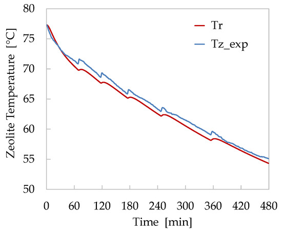
Figure 9.
Comparison of numerical (red) and experimental (blue) temperature trends of zeolite bed for the adsorption Test 5.
The comparison of numerical and experimental temperatures shows a good agreement. The calculated bed temperatures show a faster decrease during the first 60 min of the test, and subsequently, the values follow the same trend. This is probably because there is an overestimation of the heat transfer between the zeolite bed and the finned heat-exchanger. Despite this initial discrepancy, the maximum difference recorded between the temperatures measured and those calculated remained below 2.5%. Furthermore, the implemented kinetics model has proven to respond adequately to the pressure variations induced by the pool heating to maintain the internal pressure of the chamber within the range 13–15 mbar. During these peaks of vapour production, however, the model appears to respond slower than the reactor’s real behaviour. This circumstance suggests a more accurate refinement of the kinetics coefficient adopted in the LDF model for the current simulation.
In Figure 10, the results obtained applying the model to the desorption Test 3 are shown. In this case study, the modified model, as described in Section 2.2.3, has been introduced in order to take into account the different operational conditions, consisting in the absence of the water pool at the bottom of the reactor and the use of the vacuum pump to extract the water vapour from the reaction chamber. These operative conditions appeared an interesting test bench for the simulation model.
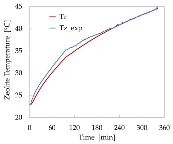
Figure 10.
Comparison of numerical (red) and experimental (blue) temperature trends of zeolite bed for the desorption Test 3.
Also, in this case, the comparison of numerical and experimental temperatures shows a good agreement. During the initial heating of the zeolite bed, the model shows a slower increase of the temperature probably due to an underestimation of the heat transferred by the finned heat-exchanger to the zeolite bed. This difference grows progressively until the vacuum pump is used. Starting from this instant, the calculated temperature gradually approaches the measured one, until they completely overlap during the last two hours of the test. In this case, the maximum difference recorded between the two temperatures is about 4.8%. Nevertheless, the model proved to be able to follow the reactor temperature trends both during the initial faster phase and during the subsequent one, when the presence of the vacuum pump caused a slowdown in the desorption process.
The optimal agreement between the calculated and experimental data, as highlighted in the two case studies examined, demonstrates the high predictive capacity of the implemented model.
4. Conclusions
The all-in-one configuration of the zeolite thermal storage makes it possible to maintain satisfying energy performances, even if they are lower than that of the separated configuration. The thermal behaviour of the system is penalised by the contemporary presence of a hot and cold zone within the same chamber. During the desorption, it is necessary to carefully use the cooling zones for the vapour condensation. Their geometrical design and reciprocal position with respect to the zeolite bed have a strong impact on the response of the zeolite when it is heated. The duration of the charging process is strongly affected by the adverse effect of the condensation on the zeolite heating and desorption. Anyhow, the compact configuration assures a very simple and unexpensive layout and simplicity of use. During the adsorption phase, the presence of the pool assures an important chilling effect which could be used as a double effect system, i.e., for end-users with cooling and heating demand. The all-in-one configuration can be considered a very promising configuration to mitigate the installation cost of the adsorption systems, at the same time maintaining acceptable energy performances. From the technical point of view, it is necessary to study in depth the geometry of the cold plate and pool so as to have a good compromise between their condensing capability and the possible detrimental effect on the charging and discharging effects. Further, future work is required from the simulation point of view introducing a more structured CFD model with a multiphysic approach in order to assess the tri-dimensional effects due to the position of the subparts of the all-in-one reactor.
Author Contributions
Conceptualisation, M.D.P., V.S., F.B., and R.G.; methodology, V.S. and R.G.; validation, M.D.P., V.S., and R.G.; investigation, M.D.P., V.S., and R.G.; writing—original draft preparation, M.D.P., V.S., F.B., and R.G.; writing—review and editing, M.D.P., F.B., V.S., and R.G.; supervision, V.S. and R.G.; project administration, M.D.P. and V.S.; funding acquisition, M.D.P. and V.S. All authors have read and agreed to the published version of the manuscript.
Funding
This research has been carried out in the frame of the project SUNSTORE, funded by Ricerca di Sistema Elettrico Nazionale (ITALY).
Acknowledgments
The computing resources and the related technical support used by ENEA for this work have been provided by CRESCO/ENEAGRID High-Performance Computing infrastructure and its staff [31]. CRESCO/ENEAGRID High-Performance Computing infrastructure is funded by ENEA, the Italian National Agency for New Technologies, Energy and Sustainable Economic Development, and by Italian and European research programmes, see http://www.cresco.enea.it/english for information.
Conflicts of Interest
The authors declare no conflict of interest.
Nomenclature
Latin symbols
| A | area (m2) |
| b | isotherm model affinity (1/Pa) |
| cp | specific heat capacity (J/kg K) |
| C | heat capacity (J/kg) |
| Deff | effective diffusivity (m2/s) |
| e | effectiveness (-) |
| h | convective heat transfer coefficient (J/kg K) |
| k | conductivity (W/m K) |
| M | mass (kg) |
| mass flow (kg/s) | |
| p | pressure (Pa) |
| Q | thermal energy (J) |
| R | particle radius (m) |
| Rw | universal constant for water vapour (J/kg K) |
| t | time (s) |
| T | temperature (K) |
| U | overall heat transfer coefficient (W/m2K) |
| x | water uptake (kg/kg) |
| ΔH | adsorption enthalpy (J/kg) |
| Δx | variation of water uptake (kg/kg |
Greek symbols
| ε | porosity (-) |
| Γ | flow rate (kg/s) |
| ρ | density (kg/m3) |
Subscripts
| ads | adsorption |
| b | bed |
| B | bath |
| c | charging |
| cond | condensation |
| d | discharging |
| des | desorption |
| e | external |
| E/C | evaporative/cooling |
| end | end of the process |
| evap | evaporation |
| eq | equilibrium |
| f | fluid |
| he | heat-exchanger |
| HTF | heat transfer fluid |
| i | internal |
| in | inlet |
| LDF | linear driving force |
| max | maximum |
| out | outlet |
| p | particle |
| r | reactor |
| sat | saturation |
| sens | sensible |
| start | start of the process |
| v | vapour |
| z | zeolite |
References
- Koçak, B.; Fernandez, A.I.; Paksoy, H. Review on sensible thermal energy storage for industrial solar applications and sustainability aspects. Sol. Energy 2000, 209, 135–169. [Google Scholar] [CrossRef]
- Ahmadi, A.; Ehyaei, M.A.; Doustgani, A.; El Haj, M.A.; Hmida, A.; Jamali, D.H.; Kumar, R.; Li, Z.X.; Razmjoo, A. Recent residential applications of low-temperature solar collector. J. Clean. Prod. 2021, 279, 123549. [Google Scholar] [CrossRef]
- Kumar, D. Hyper-temporal variability analysis of solar insolation with respect to local seasons. Remote Sens. Appl. Soc. Environ. 2019, 15, 100241. [Google Scholar] [CrossRef]
- Alva, G.; Liu, L.; Huang, X.; Fang, G. Thermal energy storage materials and systems for solar energy applications. Renew. Sustain. Energy Rev. 2017, 68, 693–706. [Google Scholar] [CrossRef]
- Stritih, U.; Osterman, E.; Evliya, H.; Butala, V.; Paksoy, H. Exploiting solar energy potential through thermal energy storage in Slovenia and Turkey. Renew. Sustain. Energy Rev. 2013, 25, 442–461. [Google Scholar] [CrossRef]
- Gautam, A.; Saini, R.P. A review on sensible heat based packed bed solar thermal energy storage system for low temperature applications. Sol. Energy 2020, 207, 937–956. [Google Scholar] [CrossRef]
- Liu, M.; Sun, Y.; Bruno, F. A review of numerical modelling of high-temperature phase change material composites for solar thermal energy storage. J. Energy Storage 2020, 29, 101378. [Google Scholar] [CrossRef]
- Gautam, A.; Saini, R.P. A review on technical, applications and economic aspect of packed bed solar thermal energy storage system. J. Energy Storage 2020, 27, 101046. [Google Scholar] [CrossRef]
- Mao, Q. Recent developments in geometrical configurations of thermal energy storage for concentrating solar power plant. Renew. Sustain. Energy Rev. 2016, 59, 320–327. [Google Scholar] [CrossRef]
- Dahash, A.; Ochs, F.; Bianchi Janetti, M.; Streicher, W. Advances in seasonal thermal energy storage for solar district heating applications: A critical review on large-scale hot-water tank and pit thermal energy storage systems. Appl. Energy 2019, 239, 296–315. [Google Scholar] [CrossRef]
- Li, G. Sensible heat thermal storage energy and exergy performance evaluations. Renew. Sustain. Energy Rev. 2016, 53, 897–923. [Google Scholar] [CrossRef]
- Hesaraki, A.; Holmberg, S.; Haghighat, F. Seasonal thermal energy storage with heat pumps and low temperatures in building projects—A comparative review. Renew. Sustain. Energy Rev. 2015, 43, 1199–1213. [Google Scholar] [CrossRef]
- Shukla, A.; Kant, K.; Sharma, A. Solar still with latent heat energy storage: A review. Innov. Food Sci. Emerg. Technol. 2017, 41, 34–46. [Google Scholar] [CrossRef]
- Tao, Y.B.; He, Y.-L. A review of phase change material and performance enhancement method for latent heat storage system. Renew. Sustain. Energy Rev. 2018, 93, 245–259. [Google Scholar] [CrossRef]
- Agyenim, F.; Hewitt, N.; Eames, F.; Smyth, M. A review of materials, heat transfer and phase change problem formulation for latent heat thermal energy storage systems (LHTESS). Renew. Sustain. Energy Rev. 2010, 14, 615–628. [Google Scholar] [CrossRef]
- Mehari, A.; Xu, Z.Y.; Wang, R.Z. Thermal energy storage using absorption cycle and system: A comprehensive review. Energy Convers. Manag. 2020, 206, 112482. [Google Scholar] [CrossRef]
- Ibrahim, N.I.; Al-Sulaiman, F.A.; Nasir, A.F. Solar absorption systems with integrated absorption energy storage–A review. Renew. Sustain. Energy Rev. 2018, 82, 1602–1610. [Google Scholar] [CrossRef]
- Gordeeva, L.G.; Yu, I.A. Adsorptive heat storage and amplification: New cycles and adsorbents. Energy 2019, 167, 440–453. [Google Scholar] [CrossRef]
- Demir, H.; Mobedi, M.; Ülkϋ, S. A review on adsorption heat pump: Problems and solutions. Renew. Sustain. Energy Rev. 2008, 12, 2381–2403. [Google Scholar] [CrossRef]
- Vasta, S.; Brancato, V.; La Rosa, D.; Palomba, V.; Restuccia, G.; Sapienza, A.; Frazzica, A. Adsorption Heat Storage: State-of-the-Art and Future Perspectives. Nanomaterials 2018, 8, 522. [Google Scholar] [CrossRef]
- Schreiber, H.; Lanzerath, F.; Reinert, C.; Grüntgens, C.; Bardow, A. Heat lost or stored: Experimental analysis of adsorption thermal energy storage. Appl. Therm. Eng. 2016, 106, 981–991. [Google Scholar] [CrossRef]
- Schreiber, H.; Lanzerath, F.; Bardow, A. Predicting performance of adsorption thermal energy storage: From experiments to validated dynamic models. Appl. Therm. Eng. 2018, 141, 548–557. [Google Scholar] [CrossRef]
- Yu, N.; Wang, R.Z.; Wang, L.W. Sorption thermal storage for solar energy. Prog. Energy Combust. Sci. 2013, 39, 489–514. [Google Scholar] [CrossRef]
- Weber, R.; Asenbeck, S.; Kerskes, H.; Drück, H. SolSpaces—Testing and performance analysis of a segmented sorption store for solar thermal space heating. Energy Procedia 2016, 91, 250–258. [Google Scholar] [CrossRef]
- Pinheiro, J.M.; Salústio, S.; Rocha, J.; Valente, A.A.; Silva, C.M. Adsorption heat pumps for heating applications. Renew. Sustain. Energy Rev. 2020, 119, 109528. [Google Scholar] [CrossRef]
- Gorbach, A.; Stegmaier, M.; Eigenberger, G. Measurement and Modeling of Water Vapor Adsorption on Zeolite 4A—Equilibria and Kinetics. Adsorption 2004, 10, 29–46. [Google Scholar] [CrossRef]
- Mette, B.; Kerskes, H.; Drück, H.; Müller-Steinhagen, H. Experimental and numerical investigations on the water vapor adsorption isotherms and kinetics of binderless zeolite 13X. Int. J. Heat Mass Transf. 2014, 71, 555–561. [Google Scholar] [CrossRef]
- Gaeini, M.; Zondag, H.A.; Rindt, C.C.M. Effect of kinetics on the thermal performance of a sorption heat storage reactor. Appl. Therm. Eng. 2016, 102, 520–531. [Google Scholar] [CrossRef]
- Son, K.N.; Richardson, T.-M.J.; Cmarik, G.E. Equilibrium Adsorption Isotherms for H2O on Zeolite 13X. J. Chem. Eng. Data 2019, 64, 1063–1071. [Google Scholar] [CrossRef]
- MATLAB. Release R2011b; The MathWorks Inc.: Natick, MA, USA, 2011. [Google Scholar]
- Iannone, F.; Ambrosino, F.; Bracco, G.; De Rosa, M.; Funel, A.; Guarnieri, G.; Procacci, P. CRESCO ENEA HPC clusters: A working example of a multifabric GPFS Spectrum Scale layout. In Proceedings of the 2019 International Conference on High Performance Computing & Simulation (HPCS), Dublin, Ireland, 15–19 July 2019; pp. 1051–1052. [Google Scholar] [CrossRef]
Publisher’s Note: MDPI stays neutral with regard to jurisdictional claims in published maps and institutional affiliations. |
© 2020 by the authors. Licensee MDPI, Basel, Switzerland. This article is an open access article distributed under the terms and conditions of the Creative Commons Attribution (CC BY) license (http://creativecommons.org/licenses/by/4.0/).