Article

Modified Silicone-SAPO34 Composite Materials for Adsorption Thermal Energy Storage Systems

1
Department of Engineering, University of Messina, Contrada di Dio Sant’Agata, 98166 Messina, Italy
2
CNR ICCOM—Institute of Chemistry of Organometallic Compounds, Via G. Moruzzi, 1-56124 Pisa, Italy
3
Department of Energy, Politecnico di Milano, Via Lambruschini 4, 20156 Milano, Italy
4
Istituto per le Tecnologie Avanzate per l’Energia (ITAE-CNR), Via S. Lucia sopra Contesse n°5, 98126 Messina, Italy
*
Author to whom correspondence should be addressed.
Appl. Sci. 2020, 10(23), 8715; https://doi.org/10.3390/app10238715
Submission received: 30 October 2020 / Revised: 28 November 2020 / Accepted: 1 December 2020 / Published: 5 December 2020
(This article belongs to the Special Issue The State of the Art of Thermo-Chemical Heat Storage)

Abstract

:
In this work, novel silicone-SAPO34 composite materials are proposed for application in adsorption thermal energy storage systems. The innovative composite materials were obtained through a mold foaming process activated by a dehydrogenative coupling reaction between properly selected siloxane compounds. Morphology analysis by optical microscopy and measurement of the mechanical properties of the foamed materials at varying zeolite content demonstrated a quite homogeneous open-cell structure and good structural stability of the foam. Water adsorption isotherms of the adsorbent foams expanded in free space and inside paperboard were measured by a gravimetric adsorption apparatus, demonstrating that the presence of the polymeric fraction does not affect the adsorption capacity of the SAPO34 fraction added in the composite foam. Finally, main adsorption and thermodynamic properties of the proposed foam have been compared with those of other adsorbent materials, confirming the possible use of these new composite foams as adsorbent materials for adsorption thermal energy storage systems.

1. Introduction

A major research topic in the field of adsorption systems for solar thermal energy storage, air-conditioning and dehumidification processes involves the development of new or modified adsorbent materials with enhanced adsorption and thermo-physical properties, low cost, high stability, and low regeneration temperature [1,2,3,4,5]. Possible adsorbent classes are zeolites, silica gels, activated carbons, metal organic frameworks (MOFs), and composite adsorbents made of a sorbent matrix embedding a hygroscopic salt [6]. Among them, silico-aluminophosphate zeotype materials (SAPO, ALPO) are very attractive due to the low regeneration temperature (<100 °C) and optimal shape of the water adsorption equilibrium curve [7,8,9]. In closed systems research on components optimization is mainly focused on the integration between heat exchanger and adsorbent material, to create the so called adsorber [10]. Two different approaches are currently under investigation: embedding a granular adsorbent in the heat exchanger [11]; coating the heat exchanger with the adsorbent material either using a binder [12] or by direct synthesis of the zeolite over the metallic surface of the heat exchanger [13]. The first approach allows good heat transfer efficiency without significantly affecting the vapor diffusion through the adsorber if a proper grain size and dispersion is selected [14]. The second approach is based on the reduction of the contact resistance between the heat exchanger and a thin adsorbent coating (generally 0.05–0.2 mm), thus enhancing the heat transfer efficiency. However, a sufficiently high amount of adsorbent must be deposited over the heat exchanger, to avoid reduction of the achievable power density [15]. Similarly, in open systems the adsorption and desorption process is typically achieved through a honeycomb matrix impregnated with a desiccant material [16,17] or through a packed bed made of spherical beads of a sorption material [18]. In the first case, a high heat and mass exchange area between the air stream and the desiccant matrix is obtained and air pressure drop is low. Anyway, the manufacturing process of the honeycomb structure is quite complex and it requires the use of support materials (such as paper or glass fiber) and appropriate binders that partially limit the net sorption capacity of the desiccant. In the second case, packed bed can be easily realized by using beads of pure materials, without any need of binders. On the other side, this approach leads to a device with high water mass transfer resistance within desiccant beads and high air pressure drop, limiting the application of the system. Optimization of adsorber/desorber configuration in both open and closed systems is still an open issue, which heavily depends on the final application of the adsorption system [19].
Recently, an innovative silicone–zeolite foaming process has been developed in order to enhance the power density of the zeolite heat and mass exchanger in closed-cycle adsorption heat pumps and chillers [20,21]. Indeed, foamed materials, due to their intrinsic high surface area per unit mass, could allow to obtain a large amount of zeolite coating per unit of volume, and at the same time the foam porosity could act as a preferential pathway for the vapor diffusion. This approach allows improving the amount of active material embedded into the adsorbent heat exchanger and can be suitable for both open and closed systems. In a previous preliminary work, several samples of SAPO34 foams have been prepared and water adsorption isotherms have been measured by a gravimetric adsorption apparatus, demonstrating that they can adsorb a significant amount of water (up to 30 wt.%) under typical operating conditions of open-cycle adsorption systems [22]. Moreover, the tested foams exhibited sufficiently fast water sorption rate, as the silicone does not significantly reduce the transient adsorption capacity of pure zeolite.
Based on the promising results achieved in [22], in this work we assessed the feasibility of a SAPO34 foam-based innovative component for open and closed adsorption heat storage applications. Firstly, several samples with different foam formulations have been produced by varying the SAPO34 content in the range 20–60 wt.% and the corresponding water adsorption isotherms have been measured by a thermogravimetric method. Among the different tested formulations, Z60 foam (60 wt.% SAPO34 content) demonstrated the best adsorption properties, being suitable for the development of innovative components for heat storage applications. Accordingly, the Z60 foam preparation method has been further developed in order to allow the foam expansion in a partially closed environment (paperboard), to reproduce the constraints that would occur in a mold used to give the foam a specific geometry at the end of the solidification process. Morphological analysis of the Z60 foam expanded in the paperboard cavities has been carried out by optical microscopy, to evaluate the foam pores nature and size and study the interaction between foam microstructure and the paperboard support. Water vapor adsorption capacity of the obtained foam has been evaluated by thermogravimetric method and results have been compared with ones previously obtained for foams expanded in not constrained environment. Z60 foam adsorption data at equilibrium have been correlated considering the Dubinin–Asthakov approach, and the corresponding heat of adsorption has been calculated. Specific heat has been measured as a function of the SAPO34 amount by calorimetric technique. Finally, measured data of the proposed Z60 foam have been compared with properties of other available sorbent materials for heat storage purposes.

2. Materials and Methods

2.1. Sample Preparation

The composite zeolite/siloxane foam was obtained by mold foaming process. Details of compounds used for the synthesis are summarized in Table 1. As zeolite filler, a SAPO34, (AQSOA-FAM Z02, supplied by Mitsubishi Chemicals, Tokyo, Japan) with average size in the range of 4–8 μm was used. The foaming matrix is constituted by two reactants (acquired by Gelest Inc., Morrisville, NY, USA) selected in order to have a dehydrogenative coupling reaction: a Methylhydrosiloxane—dimethylsiloxane copolymer, trimethylsiloxane terminated, PMHS (M.W. 1400–1800, viscosity 15–25 cSt), and a silanol terminated polydimethylsiloxane (PDMS—M.W. 110,000, viscosity 50,000 cSt). In order to activate the reaction between the two siloxane compounds, Tin(II) 2-ethylhexanoate (Sn(II)) (supplied by Sigma Aldrich, St. Louis, Missouri, NY, USA) was used as catalyst.
Two different types of samples have been prepared in this study. In the first case the slurry has been introduced in an open mold, in order to guarantee an almost free expansion of the foam. In the second case, the slurry has been forced inside channels of a paperboard, in order to constrain the foam expansion in a similar way to what would happen in the construction of real components. As shown in Figure 1, the foamed composite sample preparation can be summarized in five main steps:
(1)
Filler dispersion. Preliminarily SAPO34 zeolite powder was gradually dispersed under vigorous magnetic stirring in the polydimethylsiloxane (PDMS) compound for about 60 s. In order to obtain a homogenous dispersion of the filler and to reduce the solution viscosity, water and ethanol solvents were added to the mixture.
(2)
Composite slurry. Afterward, the polymethylhydrosiloxane (PMHS) compound was thoroughly added in the mixture obtained in point 1, always under vigorous magnetic stirring. The stirring was maintained for 60 s until a homogenous composite slurry is obtained.
(3)
Reaction activation. The catalyst (diluted in ethanol) is gently added in the composite slurry. A vigorous mixing was applied for about 20 s.
(4)
Molding. Immediately, the catalyst activated composite slurry was poured, by using a syringe tool:
  • Into a cylindrical open mold (diameter 25 mm).
  • Into the cavities of a corrugated cardboard (inner height and base of the cross section respectively equal to 5 mm and 10 mm, channel length equal to 5 cm).
The samples rest open to air at room temperature for about 30 s, to stabilize the mixture in the free surface area of the mold.
(5)
Foaming. Finally, the foaming process was triggered putting the filled samples into an oven set at 60 °C for 24 h to allow the matrix curing. At the end of the curing process the obtained foams poured in a cylindrical mold were cut in order to get cubic samples with edge of about 20 mm.
The foamed structure is obtained during the last point 5 of the process thanks to the dehydrogenative coupling reaction between hydroxyl terminated polydimethylsiloxanes (PDMS) that react with hydride functional siloxane (PMHS) to produce foamed silicone materials, according to the following reaction:
S i O H + H S i S i O S i + H 2
The reaction of siloxane compounds leads to a polymer network in a silicone rubber [23]. As reaction product gaseous hydrogen is formed, acting as blowing agent [24]. This process is indicated as chemical blowing process. Furthermore, a physical blowing phenomenon occurs during the crosslinking reaction, due to the evaporation of the solvent during the curing stage. The combination of chemical and physical blowing allows to obtain a microporous structure with good foaming ration and well-interconnected bubbles.
Three different foam formulations were produced by varying the SAPO34 filler content in the range 20–60 wt.% of the PDMS-PMHS siloxane matrix. All produced formulations with details of compound amounts are summarized in Table 1. The samples were codified by means a prefix “Z” coupled to a number. Z is referred to the zeolite based foam, instead the number indicates the amount (%) of the SAPO34 zeolite added to the siloxane matrix; i.e., Z20 code is referred to a composite foam filled by 20 wt.% of SAPO34. The term Z0 is used to refer to pure foam without zeolite. (The bold explanation)

2.2. Experimental Equipment and Methodology

2.2.1. Dynamic Water Vapor Adsorption Analyzer

Water adsorption isotherms of pure zeolite SAPO34 and of the adsorbent foams Z20, Z40, and Z60 have been measured by a gravimetric adsorption apparatus (Aquadyne DVS). The anhydrous reference state was obtained at 80 °C in nitrogen atmosphere and at ambient total pressure. Experimental uncertainty of temperature, relative humidity and mass of the apparatus are respectively: ±0.2 °C; from ±0.8% at 20 °C to ±1.8% at 70 °C; 1.0 μg plus 0.001% of measured mass.
The anhydrous reference state of pure zeolite or foams is obtained by drying each sample in the chamber of the equipment for several hours (around 8–10 h), until no weight variation is observed, at the aforementioned conditions. Then, the chamber is set at the desired temperature (30 °C, 50 °C, or 70 °C) and sorption curve is determined by evaluating the sample mass variation at different relative humidity. Each step is assumed in steady state conditions when mass variation is lower than 0.0001% in a minute.

2.2.2. Differential Scanning Calorimetry

The specific heat was evaluated by means of calorimetric measurement performed by DSC1 METTLER TOLEDO. The instrument before all measurements was calibrated by pure indium sample. The test was performed measuring the baseline of the empty crucible, the baseline of the sample, and the baseline of the reference material (sapphire). Subsequently, the difference between sample and empty crucible is defined as H, while the difference between reference and empty crucible is defined as h. Knowing these values, the specific heat of the sample under investigation can be calculated as
c p ,   s a m p l e = H h   m r e f m s a m p l e   c p , r e f
The used protocol for each measurement is as follows, consistent with the American Standard ASTM E1269-11:
-
Drying of the foam sample up to 85 °C over night.
-
Loading of the dry adsorbent material inside a crucible and sealing it to prevent humidity adsorption.
-
Measurement of the specific heat in temperature interval between 30 °C and 70 °C, employing the standard specific heat method against a reference material (sapphire method). The heating rate for specific heat measurement is usually 2 °C min−1.

2.2.3. Other Equipment

Optical microscopy was carried out by using a three-dimensional digital microscope (Hirox HK-8700). Mechanical properties of the prepared foams were measured by using a universal testing machine (2.5 kN Zwick Line) equipped with a 2.5 kN load cell (sensitivity of 0.001 N).

3. Results

In this section physical properties of prepared samples of silicone–zeolite foams are reported and discussed. Results are shown first for samples obtained through a quasi-free expansion process and, then, for samples prepared inside paperboard channels. Tests have been carried out in the temperature range between 30 °C and 70 °C, which is of interest for low temperature heat storage applications.

3.1. Composite Foams Obtained through Almost Free Expansion Process

3.1.1. Morphology and Mechanical Properties

The macroporous morphology of the composite foams at varying zeolite content is reported in Figure 2. All specimens evidenced a micro-structure without macroscopic defects indicating a suitable foaming process. A quite homogeneous cell geometry and distribution can be also highlighted. Although, some differences among foams, at varying zeolite content can be observed. In particular, at low zeolite content (foam Z20), the foam morphology is characterized by well-interconnected bubbles, suggesting the presence of micro channels among the bubbles. In fact, these foams are characterized by an open/close cell structure. The bubble walls are structurally compact, thick and defect-free. This suggests that mechanically unstable regions in the foams were not recognized. During the foaming process, the expansion of the siloxane matrix takes place because of hydrogen gas evolution induced by dehydrogenative coupling reaction. This leads to an expansion of the structure with progressively larger macropores. This effect is more evident as higher is the zeolite content in the composite foam. At increasing filler content, the viscosity of slurry significantly increases, thus hindering the hydrogen induced bubbling growth. As a consequence, foams with high zeolite content (foam Z60) showed numerous small bubbles homogeneously distributed. Some small and local macropores were occasionally evidenced.
In order to better relate composite foam morphology and its mechanical performances, Table 2 summarizes apparent density (calculated as weight to volume ratio) and elastic properties for all composite zeolite foams. As reference, the not filled foam was also added. This information, can provide a direct practical information on the use and handling conditions of the material.
Due to the zeolite filler addition, a gradual increase of elastic modulus and compression stress can be observed. In particular, the Foam Z60 showed an elastic modulus of 1.552 MPa, about two orders of magnitude higher than the unfilled one (Foam Z0, 0.031 MPa).
As a consequence of the soft behavior of the microporous matrix, all composite foams exhibited a quite low compression stress. Although, as observed for the elastic modulus, a progressive increase at increasing the zeolite amount, was observed. However, although an increase in compressive stress takes place, the modulus increase limits the foam compressibility, representing a warning to pay attention during practical use and handling of the material.
This behavior can be ascribed to the foam microstructure. At increasing amount of adsorbent filler in the foam, apparent density of the foam increases due to a densification effect of the composite material induced by the filler addition. The foaming ratio is gradually reduced as evidenced by comparing the density of Foam Z60 that is three times higher than unfilled one (foam Z0). In particular, based on calculated apparent density, it is possible to identify the foam void content (Vc), defined as
Vc =   1   Apparent   Density / Bulk   Density
where the bulk density can be calculated through the rule of the mixture of the composite constituents. The void content decreases at increasing filler content. In particular for Z0 and Z60 batches a Vc of 72.2% and 47.8% was obtained. This confirms the limited foaming for high zeolite content composite specimens.
The presence of the filler partially hinders the bubble growth during the foaming stage, mainly limiting the coalescence phenomena of the bubbles. In fact, the bubble dimension in the foams with higher amount of zeolite filler are characterized by quite lower average diameter size. The standard deviation is also reduced as confirmation of the less dispersed size distribution. However, the composite foam structure preserves the presence of microchannels, which, considering also the high permeability of the silicone matrix to water vapor, could act as preferential paths for the water vapor diffusion, potentially preserving the effective adsorbing capacity of the zeolite.

3.1.2. Adsorption Capacity

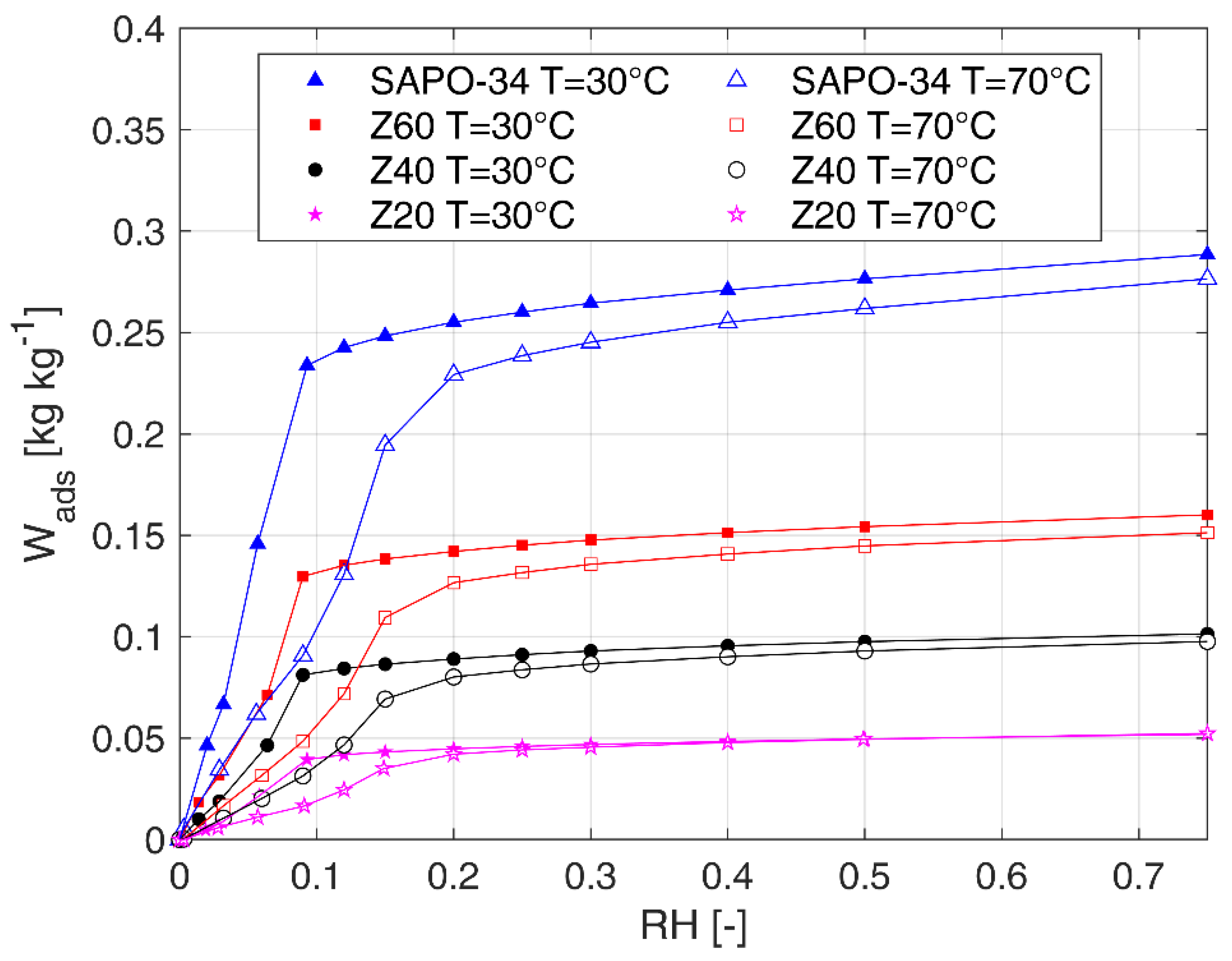
As shown in Figure 3, water adsorption isotherms of pure SAPO34 and of Z20, Z40, and Z60 have been measured at 30 °C and 70 °C. The sharp uptake rise at low relative humidity (RH < 15–20%) and, more generally, the isotherm shape of the pure material is similarly present also in the foams proposed in this work. At each step of relative humidity, sorption capacities of Z20, Z40, and Z60 are lower than one of pure SAPO34. This effect is related to the presence of silicone (included in the reference mass of each sample) that does not participate in the sorption process. As discussed in a previous research [22], the reduced adsorption capacity is in agreement with the zeolite mass fraction. In fact, if the adsorption capacity were referred only to the dry mass of zeolite of each sample, adsorption isotherm curves of pure desiccant and of foams would be very close (maximum reduction around 14%).
Based on obtained results, Z60 foam keeps a high sorption capacity of the SAPO34 and, therefore, can be effectively used to develop innovative components for heat storage applications.
Experimental data at 30 °C and 70 °C and additional ones at 50 °C have been used to fit parameters of sorption isotherm curves proposed by Dubinin–Asthakov (D-A) [25]:
W a d s = W 0   e ( A E ) n = W 0   e ( R T   l n ( R H ) E ) n
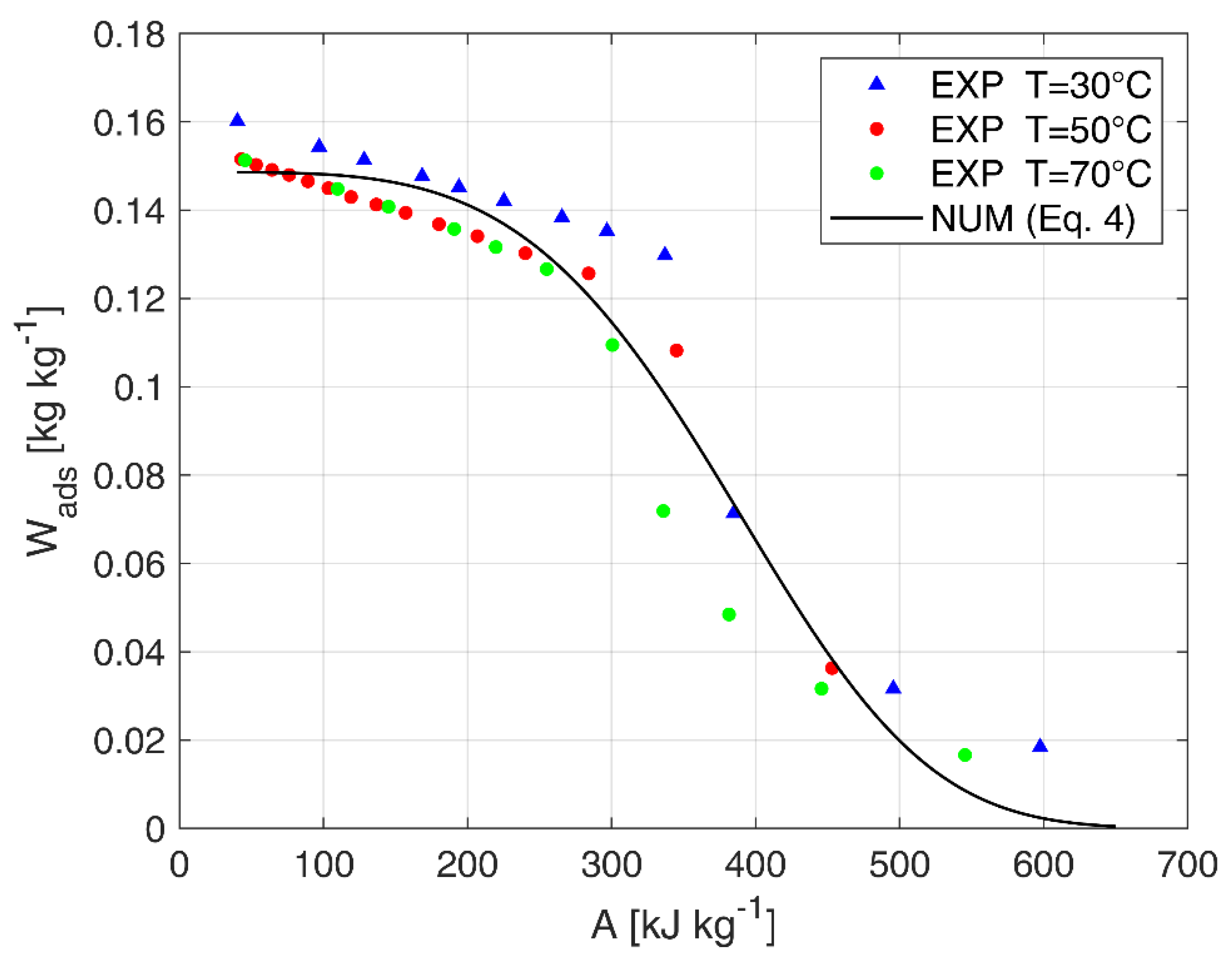
where W0 is the maximum sorption capacity, A is the adsorption potential, E is the characteristic D-A parameter and n is an exponent describing the surface heterogeneity. The adopted fitting approach has already been used by other researchers [26,27] for SAPO34, with satisfactorily results. Parameters can be fitted by using entire data between minimum and maximum sorption capacity (obtaining one set of parameters) [26] or by dividing the uptake curve in different sections (obtaining multiple sets of parameters) [27]. Authors adopted the first approach because it is particularly simple and obtained correlation can be easily implemented in phenomenological models of the device, although the second one generally leads to a more accurate correlation. Obtained parameters of Z60 are W0 = 0.1486 kg kg−1, E = 420 kJ kg−1 and n = 4.01 with R-square equal to 0.9376. Measured adsorption equilibrium curves and numerical results obtained through Equation (4) are reported in Figure 4.
Finally, according to the adopted D-A approach, it is worth specifying that the heat of adsorption can been calculated as:
Q a d s = λ + A
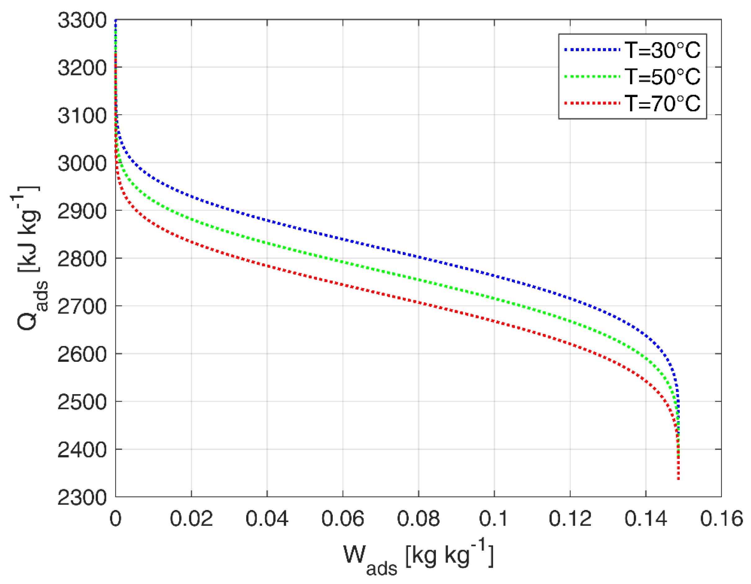
where λ is the enthalpy of evaporation of water at a given temperature and A is the adsorption potential. In Figure 5, the heat of adsorption of Z60 is calculated and plotted against the sorption capacity for different temperatures (by using Equations (4) and (5)).
Although the evaluation of the adsorption kinetics is not the scope of this work, it is worth specifying that silicone foam does not affect significantly adsorption kinetics. Sorption characteristic time of pure zeolite and foamed samples is of the same magnitude order.

3.1.3. Specific Heat

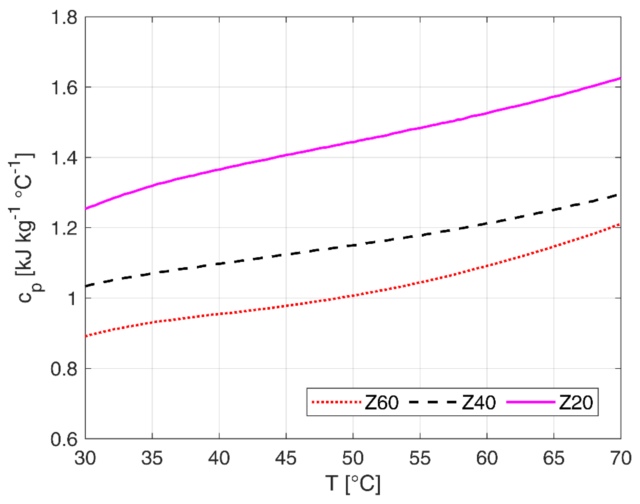
Figure 6 reports the specific heat cp evaluated for Z20, Z40, and Z60 foams in anhydrous state and in the temperature range 30–70 °C. As expected, in all cases the specific heat increases as temperature increases. Moreover, the specific heat is higher in samples with lower SAPO34 loading, ranging from about 0.85 kJ kg−1 °C−1 (foam Z60) to about 1.6 kJ kg−1 °C−1 (foam Z20). This behavior is due to the higher specific heat of the polymeric phase with respect to the pure SAPO34 fraction, which is characterized by relatively low specific heat (0.82–0.94 kJ kg−1 °C−1 [28]). The low specific heat of the Z60 foam is a physical property of interest for the application of thermal energy storage. In fact, it leads to a decrease in the energy exchanged to vary the temperature of the material in the charging and discharging cycles.

3.2. Paperboard Foamed Samples

3.2.1. Morphology

Preliminarily, optical images to assess the morphology of the foamed structure in the paperboard cavities were performed. In particular, the corrugated paperboard samples were cut in transversal and longitudinal direction to corrugation, a and b lines, respectively, as schemed in the drawing reported in Figure 7. No evidence of material loss after the cutting step was observed indicating a good structural stability of the foam filled in the cardboard cavities.
At first analyzing the transversal direction (Figure 7a), the foam morphology shows the clear presence of bubbles randomly distributed along the whole cross-section. The size and shape of the bubbles can be varied according to the coalescence phenomena that take place during foaming. This results in a heterogeneous distribution of bubble geometries [29]. However, the foam is homogeneously distributed. The adsorbent composite material is also present in the narrow cavities formed between the wave and plain sheets of the cardboard. This indicates that the filling process of the cardboard channels was effective and suitable for the viscosity of the composite slurry. However, it should be pointed out that small debonding area at the interface with the cardboard occurred, probably due to a non-optimal interaction of the composite with the surface of the cardboard. This aspect is much more evident by analyzing the longitudinal section (shown in Figure 7b). In this cross section direction, analyzing the foam/paperboard interface, some delamination lines alternate between large anchoring areas. This is imputable to the foaming process that takes place inside the cavity. The stress state induced by the increase in volume, during the bubble formation, entail the formation of shear stresses along the walls [30], that, considering the progressive solidification of the matrix during the curing, trigger cracks and delamination at the foam/paperboard interface. Although, these localized damages do not lead in the mechanical stability loss of the foam, which is always compact and not easily removable by the touch.

3.2.2. Adsorption Capacity

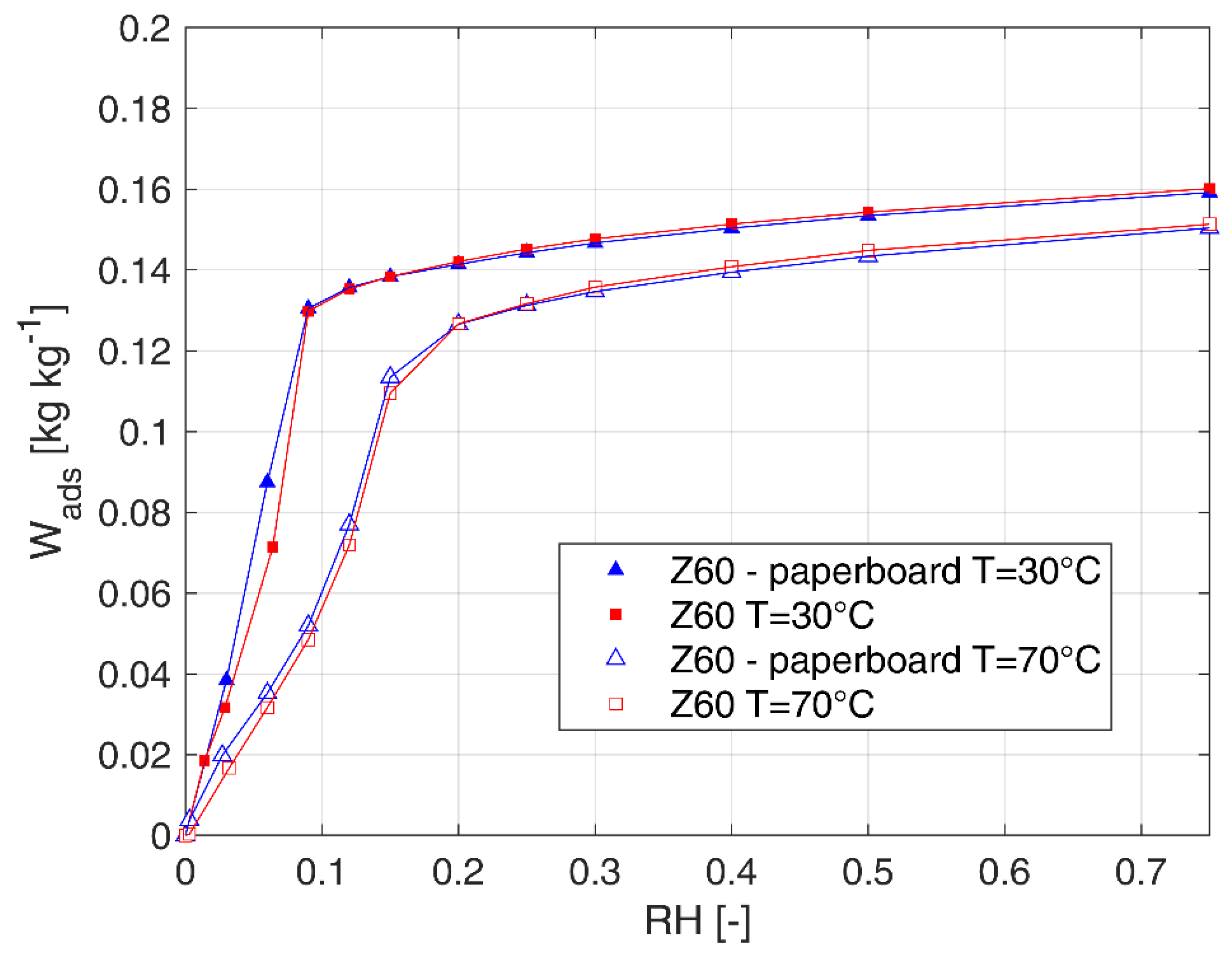
Same samples of foam prepared in the paper board have been tested in dynamic vapor sorption analyzer in order to obtain equilibrium adsorption isotherms at 30 °C and 70 °C. It is worth specifying that only pure foam has been analyzed without any cardboard part. In Figure 8 sorption isotherms of foam expanded in the paperboard are compare with ones previously obtained through a quasi-free expansion in open cylinders, as reported in Section 3.1. It is possible to state that the constraint related to the presence of the paperboard does not affect the sorption capacity of the foam. Therefore, sorption capacity data and Dubinin–Asthakov coefficients discussed in Section 3.1.2 can be effectively used also for Z60 prepared in the paperboard.

4. Comparison with Other Storage Materials

As shown in [31], several classes of materials are available which can fit the requirements for heat storage applications. Table 3 reports the thermo-physical properties of sorbents suitable for application in thermal energy storage systems and compares them with the measured data for Z60.
In particular, thermal conductivity for Z60 sample was experimentally measured by means of C- Therm TCi, a specific tool that allows the evaluation of the thermal conductivity and the effusiveness of the materials (solids, liquids, powders and slurries) using the technique defined “Modified Transient Plane Source (MTPS)”, compliant with the ASTM D7984 standard.
The other data presented are, instead, taken from literature while the ones on heat of adsorption are based on the experimental measurements.
It is worth noticing that Z60 possesses enhanced properties for application in devices for heat storage, however the identification of the best material for heat storage is extremely application-related. Indeed, the operating conditions under which the material is employed can strongly influence its overall performance.
As showed in the sections above, Z60 can be effectively regenerated at lower temperatures, significantly below 100 °C still having a higher uptake under the typical boundary conditions of thermal energy storage.
Table 3 also shows as newly developed materials, such as MOFs and composites, exhibit also good properties for heat storage applications, however such classes of materials are still expensive or not commercially available. Classical materials (silica-gels, activated carbons, and zeolites), instead, are cheap and easily available, but present the worst performances.

5. Conclusions

Novel silicone-SAPO34 composite materials have been proposed for application in adsorption thermal energy storage systems. Morphological aspects and mechanical properties at varying SAPO34 content (range 20–60 wt.%) were investigated, demonstrating homogeneous open-cell structure and good structural stability of the foam. Water adsorption measurement carried out by thermogravimetric system evidenced high adsorption capacity of the composite materials.
Based on aforementioned considerations, the foam can be used to develop scaled up prototypes of adsorbers for both open and closed systems for heat storage. Verification of the foam stability to aging cycles is another critical issue to be addressed in future activity.

Author Contributions

Conceptualization, L.C., S.D.A., and A.F.; methodology, S.D.A., L.C., and A.F.; investigation, L.C., S.D.A., S.V., V.B., and A.F.; data curation, L.C., S.D.A., S.V., and V.B.; writing—original draft preparation, S.D.A., L.C., S.V., and A.F.; writing—review and editing, S.D.A., L.C., S.V., and A.F.; supervision, S.D.A. and A.F. All authors have read and agreed to the published version of the manuscript.

Funding

This research received no external funding.

Conflicts of Interest

The authors declare no conflict of interest.

References

  1. Li, T.X.; Wang, R.Z.; Li, H. Progress in the development of solid–gas sorption refrigeration thermodynamic cycle driven by low-grade thermal energy. Prog. Energy Combust. Sci. 2014, 40, 1–58. [Google Scholar] [CrossRef]
  2. Palomba, V.; Frazzica, A. Recent advancements in sorption technology for solar thermal energy storage applications. Sol. Energy 2019, 192, 69–105. [Google Scholar] [CrossRef]
  3. Zouaoui, A.; Zili-Ghedira, L.; Nasrallah, S.B. Open solid desiccant cooling air systems: A review and comparative study. Renew. Sustain. Energy Rev. 2016, 54, 889–917. [Google Scholar] [CrossRef]
  4. Jani, D.B.; Mishra, M.; Sahoo, P.K. Solid desiccant air conditioning—A state of the art review. Renew. Sustain. Energy Rev. 2016, 60, 1451–1469. [Google Scholar] [CrossRef]
  5. Zheng, X.; Ge, T.S.; Wang, R.Z. Recent progress on desiccant materials for solid desiccant cooling systems. Energy 2014, 74, 280–294. [Google Scholar] [CrossRef]
  6. Henninger, S.K.; Ernst, S.-J.; Gordeeva, L.G.; Bendix, P.; Fröhlich, D.; Grekova, A.D.; Bonaccorsi, L.; Aristov, Y.; Jaenchen, J. New materials for adsorption heat transformation and storage. Renew. Energy 2017, 110, 59–68. [Google Scholar] [CrossRef]
  7. Zheng, X.; Wang, R.Z.; Ge, T.S.; Hu, L.M. Performance study of SAPO-34 and FAPO-34 desiccants for desiccant coated heat exchanger systems. Energy 2015, 93, 88–94. [Google Scholar] [CrossRef]
  8. Freni, A.; Maggio, G.; Sapienza, A.; Frazzica, A.; Restuccia, G.; Vasta, S. Comparative analysis of promising adsorbent/adsorbate pairs for adsorptive heat pumping, air conditioning and refrigeration. Appl. Therm. Eng. 2016, 104, 85–95. [Google Scholar] [CrossRef]
  9. Intini, M.; Goldsworthy, M.; White, S.; Joppolo, C.M. Experimental analysis and numerical modelling of an AQSOA zeolite desiccant wheel. Appl. Therm. Eng. 2015, 80, 20–30. [Google Scholar] [CrossRef]
  10. Li, X.H.; Hou, X.H.; Zhang, X.; Yuan, Z.X. A review on development of adsorption cooling—Novel beds and advanced cycles. Energy Convers. Manag. 2015, 94, 221–232. [Google Scholar] [CrossRef]
  11. Santamaria, S.; Sapienza, A.; Frazzica, A.; Freni, A.; Girnik, I.S.; Aristov, Y.I. Water adsorption dynamics on representative pieces of real adsorbers for adsorptive chillers. Appl. Energy 2014, 134, 11–19. [Google Scholar] [CrossRef]
  12. Freni, A.; Bonaccorsi, L.; Calabrese, L.; Caprì, A.; Frazzica, A.; Sapienza, A. SAPO-34 coated adsorbent heat exchanger for adsorption chillers. Appl. Therm. Eng. 2015, 82, 1–7. [Google Scholar] [CrossRef]
  13. Bonaccorsi, L.; Calabrese, L.; Freni, A.; Proverbio, E.; Restuccia, G. Zeolites direct synthesis on heat exchangers for adsorption heat pumps. Appl. Therm. Eng. 2013, 50, 1590–1595. [Google Scholar] [CrossRef]
  14. Girnik, I.S.; Aristov, Y.I. Making adsorptive chillers more fast and efficient: The effect of bi-dispersed adsorbent bed. Appl. Therm. Eng. 2016, 106, 254–256. [Google Scholar] [CrossRef]
  15. Bauer, J.; Herrmann, R.; Mittelbach, W.; Schwieger, W. Zeolite/aluminum composite adsorbents for application in adsorption refrigeration. Int. J. Energy Res. 2009, 33, 1233–1249. [Google Scholar] [CrossRef]
  16. De Antonellis, S.; Joppolo, C.M.; Molinaroli, L. Simulation, performance analysis and optimization of desiccant wheels. Energy Build. 2010, 42, 1386–1393. [Google Scholar] [CrossRef]
  17. Zhang, Y.; Wang, R. Sorption thermal energy storage: Concept, process, applications and perspectives. Energy Storage Mater. 2020, 27, 352–369. [Google Scholar] [CrossRef]
  18. De Antonellis, S.; Colombo, L.; Freni, A.; Joppolo, C. Feasibility study of a desiccant packed bed system for air humidification. Energy 2021, 214. [Google Scholar] [CrossRef]
  19. Aristov, Y.I. Concept of adsorbent optimal for adsorptive cooling/heating. Appl. Therm. Eng. 2014, 72, 166–175. [Google Scholar] [CrossRef]
  20. Calabrese, L.; Bonaccorsi, L.; Bruzzaniti, P.; Frazzica, A.; Freni, A.; Proverbio, E. Adsorption performances of SAPO34 silicone composite foams for adsorption heat pump applications. Mater. Renew. Sustain. Energy 2018, 7, 24. [Google Scholar] [CrossRef] [Green Version]
  21. Calabrese, L.; Bonaccorsi, L.; Freni, A.; Proverbio, E. Silicone composite foams for adsorption heat pump applications. Sustain. Mater. Technol. 2017, 12, 27–34. [Google Scholar] [CrossRef]
  22. Bonaccorsi, L.; Calabrese, L.; De Antonellis, S.; Freni, A.; Joppolo, C.; Motta, M. Composite silicone-SAPO-34 foams: Experimental characterization for open cycle applications. In Proceedings of the 13th REHVA World Congress, CLIMA 2019, Bucharest, Romania, 26–29 May 2019; Volume 111, pp. 1–4. [Google Scholar]
  23. Chruściel, J.J.; Leśniak, E. Preparation of flexible, self-extinguishing silicone foams. J. Appl. Polym. Sci. 2011, 119, 1696–1703. [Google Scholar] [CrossRef]
  24. Jawhar, M.-C.D.; Blanc, D.; Chaumont, P.; Cassagnau, P. Study of the Coalescence Mechanisms During Silicone Foaming. Macromol. Mater. Eng. 2013, 299, 336–343. [Google Scholar] [CrossRef]
  25. Ruthven, D.M. Principles of Adsorption and Adsorption Processes; John Wiley & Sons: Hoboken, NJ, USA, 1984. [Google Scholar]
  26. Nienborg, B.; Helling, T.; Fröhlich, D.; Horn, R.; Munz, G.; Schossig, P. Closed Adsorption Heat Storage—A Life Cycle Assessment on Material and Component Levels. Energies 2018, 11, 3421. [Google Scholar] [CrossRef] [Green Version]
  27. Brancato, V.; Frazzica, A. Characterisation and comparative analysis of zeotype water adsorbents for heat transformation applications. Sol. Energy Mater. Sol. Cells 2018, 180, 91–102. [Google Scholar] [CrossRef]
  28. Kakiuchi, H.; Shimooka, S.; Iwade, M.; Oshima, K.; Yamazaki, M.; Terada, S.; Watanabe, H.; Takewaki, T. Novel Water Vapor Adsorbent FAM-Z01 and its Applicability to an Adsorption Heat Pump. Kagaku Kogaku Ronbunshu 2005, 31, 361–364. [Google Scholar] [CrossRef]
  29. Calabrese, L.; Brancato, V.; Palomba, V.; Frazzica, A.; Cabeza, L.F. Assessment of the hydration/dehydration behaviour of MgSO4∙7H2O filled cellular foams for sorption storage applications through morphological and thermo-gravimetric analyses. Sustain. Mater. Technol. 2018, 17, 00073. [Google Scholar] [CrossRef]
  30. Calabrese, L.; Bonaccorsi, L.; Bruzzaniti, P.; Freni, A.; Proverbio, E. Morphological and functional aspects of zeolite filled siloxane composite foams. J. Appl. Polym. Sci. 2018, 135, 45683. [Google Scholar] [CrossRef]
  31. Vasta, S.; Brancato, V.; La Rosa, D.; Palomba, V.; Restuccia, G.; Sapienza, A.; Frazzica, A. Adsorption Heat Storage: State-of-the-Art and Future Perspectives. Nanomaterials 2018, 8, 522. [Google Scholar] [CrossRef] [Green Version]
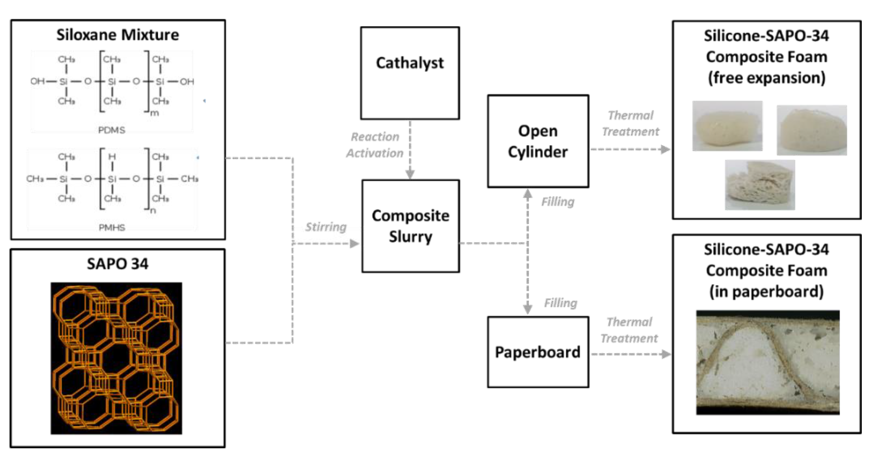
Figure 1. Preparation steps of the silicone-SAPO34 composite foam.
Applsci 10 08715 g001
Figure 2. Macroporus morphology of composite foams at increasing zeolite content.
Applsci 10 08715 g002
Figure 3. Adsorption capacity of pure SAPO34 and zeolite foams at different temperature.
Applsci 10 08715 g003
Figure 4. Adsorption capacity Z60 zeolite foam at different temperatures as a function of the adsorption potential.
Applsci 10 08715 g004
Figure 5. Z60 zeolite foam: heat of adsorption as a function of adsorption capacity at different temperatures.
Applsci 10 08715 g005
Figure 6. Zeolite foam: specific heat of Z20, Z40, and Z60 foams.
Applsci 10 08715 g006
Figure 7. Optical images of cross-section corrugated paperboard filled with zeolite foam.
Applsci 10 08715 g007
Figure 8. Adsorption capacity of pure Z60 zeolite foams expanded in free space (open cylinder) and inside paperboard at different temperatures.
Applsci 10 08715 g008
Table 1. Siloxane solution compositions (wt.%) at varying zeolite content.
ComponentZ0Z20Z40Z60
PDMS—Siloxane42.6%37.4%29.8%21.7%
PMHS—Siloxane21.3%18.7%14.9%10.9%
Ethanol—Solvent14.9%12.3%10.3%7.6%
Water—Solvent10.6%8.7%7.4%5.4%
Sn(II)—Catalyst10.6%8.7%7.4%5.4%
Zeolite—Filler0%14.2%30.2%48.9%
Zeolite/Foam0%20%40%60%
Table 2. Density and elastic properties for all composite zeolite foams.
Component Z0Z20Z40Z60
Apparent Density (g cm3)average0.270.300.370.91
Stand. Dev.0.0210.0330.0580.127
Average diameter (mm)average1.211.070.660.26
Stand. Dev.0.970.850.550.18
Elastic Modulus (MPa)average0.0310.0500.0551.552
Stand. Dev.0.0050.0060.0090.274
Comp. Stress (30% Strain) (MPa)average0.0050.0060.0140.340
Stand. Dev.5 × 10−45 × 10−45 × 10−30.098
Table 3. Comparison of Z60 properties with sorbent material classes for heat storage.
Silica GelsZeolitesAlPOs/SAPOsCompositesMOFsActivated CarbonsZ60
Adsorption heat (kJ/kg)160/180 *50/300 *250/300 *50/250 *20/200 **45/900 ***375/450 *
Typical desorption temperatures (°C)50/8070/35060/9060/9060/15080/20060/80
Density (kg/m3)650/700650/900800/900300/6001000/2000700/750780/1030
Specific heat
(kJ/(kg °C))
0.8/0.90.85/0.950.85/0.950.95/1.050.8/1.20.8/1.50.8/1.5
Thermal conductivity
(W/(m °C))
0.15/0.200.15/0.250.15/0.250.15/0.300.10/0150.15/0.750.15/0.25
Possible refrigerantswaterwaterwaterwater, methanol, ethanolwater, methanol, ethanolmethanol, ethanol, ammoniawater
Amount of uptake exchanged in a typical cycle (kg/kg)0.03/0.10up to 0.2up to 0.25up to 0.80.16/0.40015/0.60up to 0.25
* The heat of adsorption is calculated for a cycle with Tdes = 100 °C, Tcond = 30 °C, Tads = 50 °C, Tev = 10 °C, with water as sorbate. ** The heat of adsorption is calculated from isotherms at 298 K, 303 K and 333 K, with water as sorbate. *** The range of heat of adsorption is calculated with methanol and ammonia as sorbates.
Publisher’s Note: MDPI stays neutral with regard to jurisdictional claims in published maps and institutional affiliations.