Article

Practical Model for Metamaterials in Wireless Power Transfer Systems

1
College of Electrical Engineering, Zhejiang University, Hangzhou 310000, China
2
Polytechnic Institute, Zhejiang University, Hangzhou 310000, China
*
Author to whom correspondence should be addressed.
Appl. Sci. 2020, 10(23), 8506; https://doi.org/10.3390/app10238506
Submission received: 29 October 2020 / Revised: 20 November 2020 / Accepted: 27 November 2020 / Published: 28 November 2020
(This article belongs to the Section Electrical, Electronics and Communications Engineering)

Abstract

:
Metamaterials (MTMs) with extraordinary electromagnetic properties are recently applied to wireless power transfer (WPT) systems to improve power transmission efficiency. Although theoretical progress has been made on MTMs in low frequency near field, in the operation frequency of most WPT systems (usually MHz), the design of MTMs still utilizes the model used in high-frequency applications. Therefore, a practical model of MTMs in low MHz band is proposed in this work. The resonance frequency and quality factor are used to describe the characteristics of an MTM slab. The near field WPT systems with MTMs are then modeled as electric circuits, the system efficiency is explicitly deduced, and optimization algorithms are employed to optimize the MTM resonance frequency and maximize the system efficiency. The proposed practical model is validated via a prototype wireless power transfer system operating at 6.78 MHz. Experiments show that the proposed MTM model has good accuracy for low MHz WPT systems compared with the high-frequency model. The proposed practical model of MTMs provides an accurate way to analyze the performance of MTM at low MHz frequencies and greatly benefits the future exploitation of MTM-based low-frequency near field applications.

1. Introduction

Metamaterials (MTMs) are novel artificial media consisting of a large number of microscopic unit cells and exhibiting negative permeability and/or negative permittivity on some frequencies [1,2,3,4,5,6]. Since the first experimental demonstration of a negative index of refraction [7], numerous academic achievements on MTMs have been reported including transforming optics [8], invisibility cloaks [9], and novel MTM-based antennas [10]. These researches focus on high-frequency electromagnetics or optics. Recently, MTMs have been introduced to low-frequency near field applications such as wireless power transfer (WPT) and magnetic resonance imaging (MRI) [11,12,13,14,15,16,17,18,19,20]. Unlike those in high-frequency electromagnetics, the electric and magnetic fields are almost decoupled in the near field, and thus the near field can be manipulated by single-negative MTMs [21].
The MTM-enhanced WPT system is one of the major applications of low-frequency MTMs in the near field realm. WPT attracts great attention due to its capability of feeding power easily to autonomous electronic devices, such as mobile phones, wearable products, implantable medical devices, and electric vehicles [22,23,24,25]. However, the engineering applications of the WPT systems are usually restricted by the short transfer distance and the low transmission efficiency [26]. MTM slabs are introduced in the WPT systems to enhance the evanescent wave and thus improve the power transmission efficiency [11]. Theoretical analysis and simulations have shown that the power transfer efficiency with MTMs can be improved by an order when the loss is limited [12]. Moreover, it has been experimentally confirmed that the MTM slabs enhance the WPT system efficiency by about 30%, and the location, as well as the quantity of the slabs, also has a great effect on the system performance [13,17,18,19].
In low-frequency applications, researchers have made solid contributions to the analytical work of MTMs. In previous studies, MTMs have been considered as waveguides and used for the near field imaging at 21.3 MHz [27]. Furthermore, it has been shown that the properties of an MTM unit could be described by an equivalent circuit consisting of bulk and distributed elements [28], which provides suitable theoretical guidance for the MTMs in the low-frequency near-field. In [29], the near-field manipulating device was designed utilizing biatomic MTM structure, both simulations and experiments were carried out afterward to verify the analytical predictions at 45.8 MHz.
Although some issues have been discussed and concluded in [27,28,29], the applications of MTMs in low-frequency near field systems are still faced up with many difficulties. Firstly, investigations on the characteristics of MTMs is restricted in the lower frequency (usually a few MHz) and near field range. Up to now, the equivalent circuit model has not been set up for the MTM-enhanced WPT systems. The theoretical models and parameters (for example, S-parameters) utilized in high-frequency scenarios were usually applied to low-frequency systems directly. Moreover, the measurement of the transmission efficiency is not intuitive, and the corresponding retrieval algorithm [30,31] is complicated, making the calculation awkward and unpractical. Finally, in order to make the MTM slab working at negative permeability, the resonance frequency of the slab should be slightly lower than the working frequency of the WPT system, which holds out rather high requirements on the design of PCB MTMs [32,33]. Due to the limitations of processing techniques, there is no flawless method to precisely decide the resonance frequency of the MTM slab. In a word, the research methodologies for MTM-enhanced WPT systems is still highly restricted.
In order to solve the aforementioned problems, a practical model for MTMs used in WPT systems is proposed in this work. The relative permeability of MTMs is decided by the resonance frequency and the quality factor. A numerical model is proposed in order to obtain the quality factor of the MTM slab. A practical circuit model of WPT systems with MTMs is established. The power efficiency is calculated by the resonance frequency and the quality factor of the MTM slab. An optimization algorithm is used to optimize transmission power efficiency. The proposed MTM-enhanced WPT system is validated via physical experimental studies. Unlike the calculation methods in high-frequency electromagnetics, the proposed model is more suitable for MTM-based low-frequency near field systems. The circuit model provides a more accurate and suitable way to predict the performance of WPT systems with MTM slabs.

2. Practical Model for Low-Frequency Metamaterials

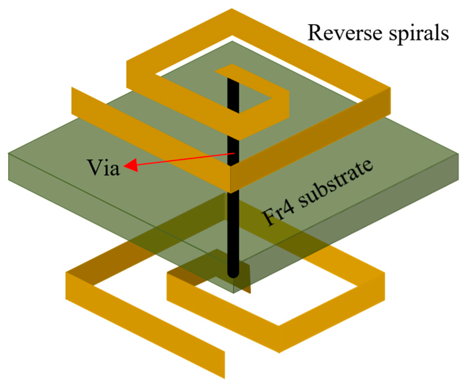
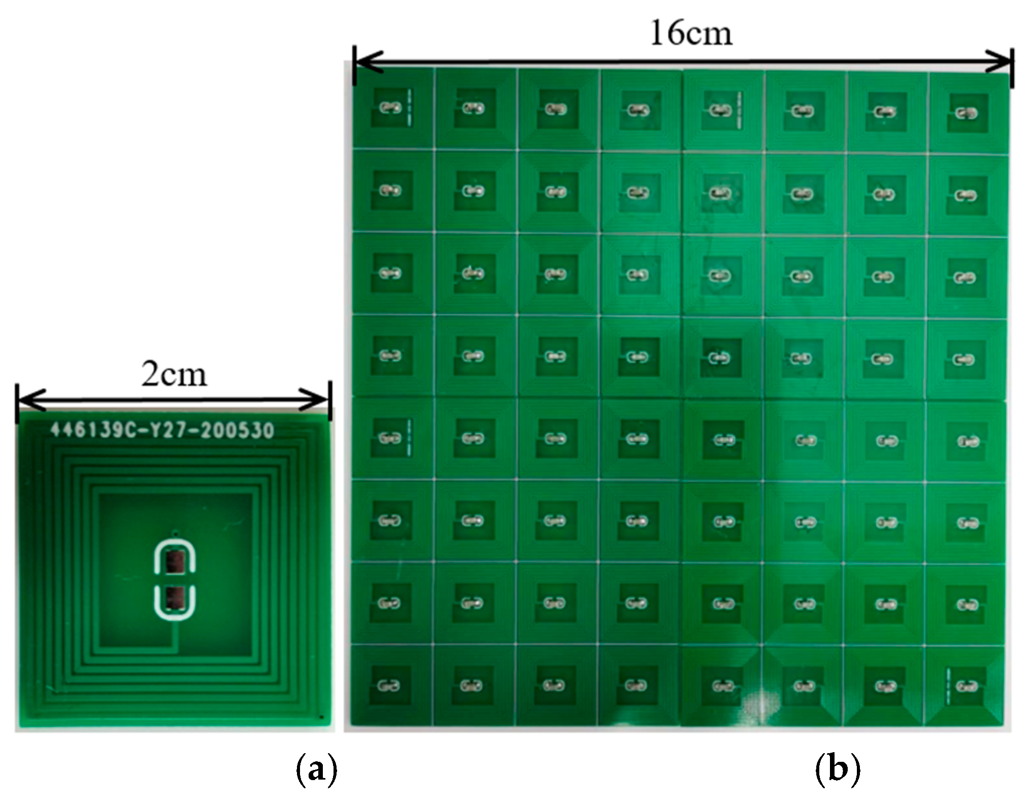
2.1. Lumped Impedance Parameters of the MTM Unit

The Swiss roll, as shown in Figure 1, is the most widely-used structure for low-frequency MTM units, which can be simply fabricated using thePrinted Circuit Board (PCB) technology. Two reverse spirals are printed on both sides of the FR4 (a kind of glass fiber composite material) substrate and connected by vias in order to reduce the MTM resonance frequency [34,35,36]. To facilitate easy adjustment of the MTM resonance frequencies, lumped capacitors are connected in series with the reverse Swiss rolls. Moreover, it has been experimentally confirmed that the lumped capacitance dominates the resonance on low frequencies [37]. Therefore, one can use lumped parameters to characterize the MTM units.
In order to design MTMs in a proper way in the near field, the lumped parameters are used to model the MTM unit. According to [37], the relative permeability μ r of the MTM modeled by the lumped parameters is given in (1):
μ r = 1 + F ω 2 ω 2 + j ω ( ω M / Q M ) + ω M 2 ,
where ω M is the resonance frequency of MTMs (related to the effective inductance and capacitance), and Q M is the quality factor of the MTMs. F is a coefficient related to the shape and the structure of the unit:
F = μ 0 ( i = 1 n S i ) 2 L e f f V u n i t ,
where L e f f is the effective inductance, V u n i t is the volume of an MTM unit, and S i is the area of ith turn in a unit with n turns in total. The coefficient F typically falls in the range of 0.16–0.50, according to [38]. Since the lumped capacitance is much larger than the parasitic capacitance of the unit, the latter can be neglected in this case. In other words, if an MTM unit is in a fixed shape and structured (fixed F) with a lumped capacitor, the property of its relative permeability can be decided by the resonance frequency (calculated by L e f f and capacitance) and the quality factor.

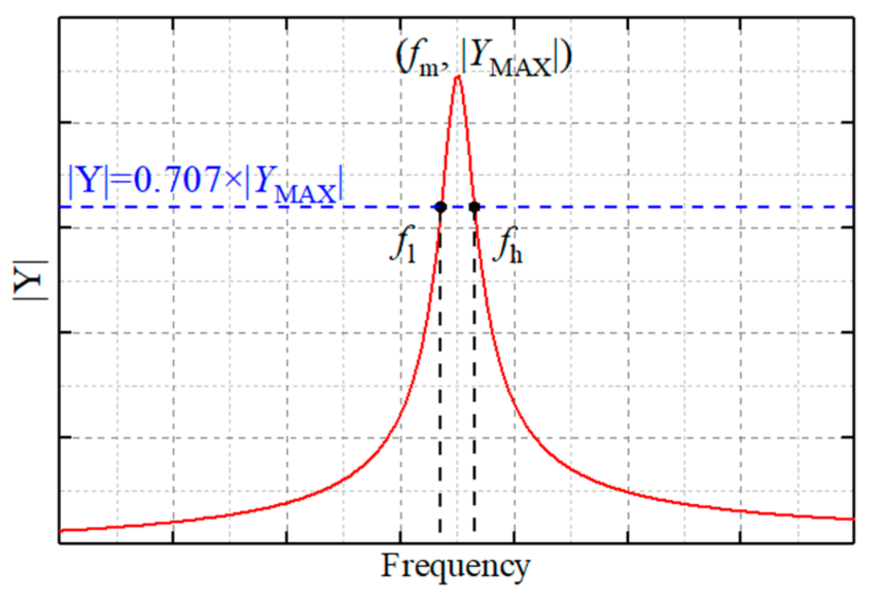
2.2. Q-Based Design Theory in the MTM Slab

MTMs used in WPT systems usually appear in the form of slabs composing of several MTM units arranged periodically, which can be regarded as effective media [39]. In order to obtain the relative permeability of the MTM slab, the common numerical model utilizing electromagnetic waves and the corresponding periodic boundary conditions is usually used as in [37]. In this numerical model, wave ports are used as the excitation, and perfect electronic conductor (PEC) and perfect magnetic conductor (PMC) are used as symmetric boundary conditions to obtain S-parameters. Then a retrieval algorithm is employed to calculate the relative permeability of the MTM slab. However, this technique is less rigorous when applied to systems on low MHz frequencies. The distance between the wave ports and the MTM unit is too large to be modeled in the low frequencies. Moreover, modeling the entire MTM slab at the unit cell level is also impractical due to the limitation of computation capability.
Nevertheless, according to the Q-based design theory [38] and (1), the relative permeability of the entire slab can be easily and accurately derived from the numerical model shown in Figure 2. The Q factor of the effective medium response is essentially equal to the Q factor of an individual resonant particle. This implies that by measuring a single fabricated MTM unit, one can simply and accurately estimate the relative permeability or permittivity of an MTM slab without complicated simulation, fabrication, or measurements. The lumped port is used as the excitation, and four PEC boundaries are used for surrounding outer boundaries. The solid model represents a two-dimensional (2D) extension of MTM units and is a proper way to describe the structure of an MTM slab. Unlike those researches inheriting high-frequency analysis methods, this is a single-port simulation without S-parameters or inversion calculations. After adding the lumped capacitor, the resonance frequency and quality factor of the MTM slab can be calculated by the admittance (Y-parameters) from the simulation results shown in Figure 3. The relative permeability of the MTM slab is then concluded by (1).
It should be pointed out that after adding the PEC, in order to tune the MTM slab, the value of the series capacitance is different from the previous results of the MTM unit. Under the periodic boundary, the value of capacitance cannot be simply calculated by ω = L C because the influence of the surrounding MTM unit needs to be considered. The proposed simulation method can exactly reflect the difference due to the periodicity of MTM units, which makes the design and frequency modulation of MTMs more accurate and reliable.

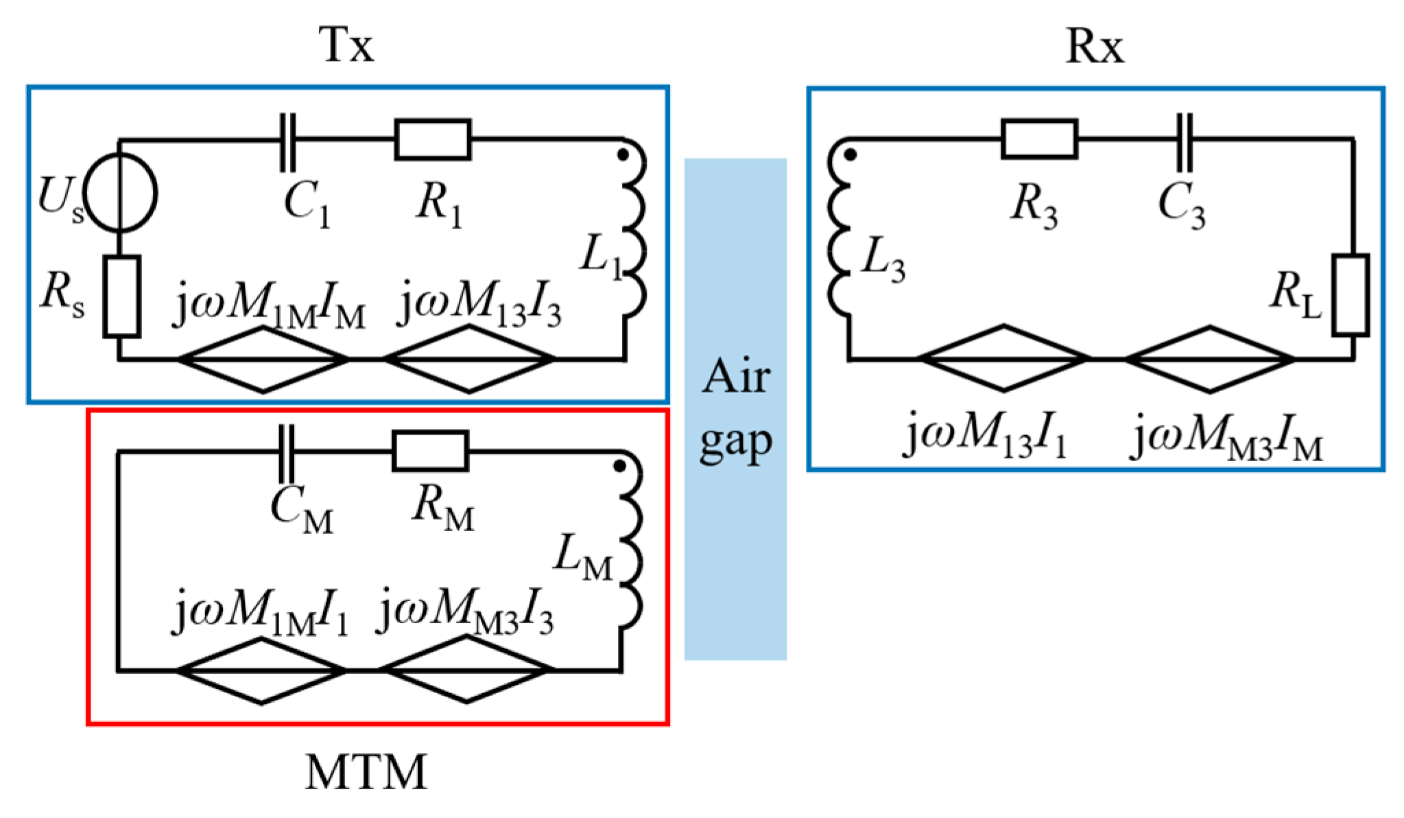
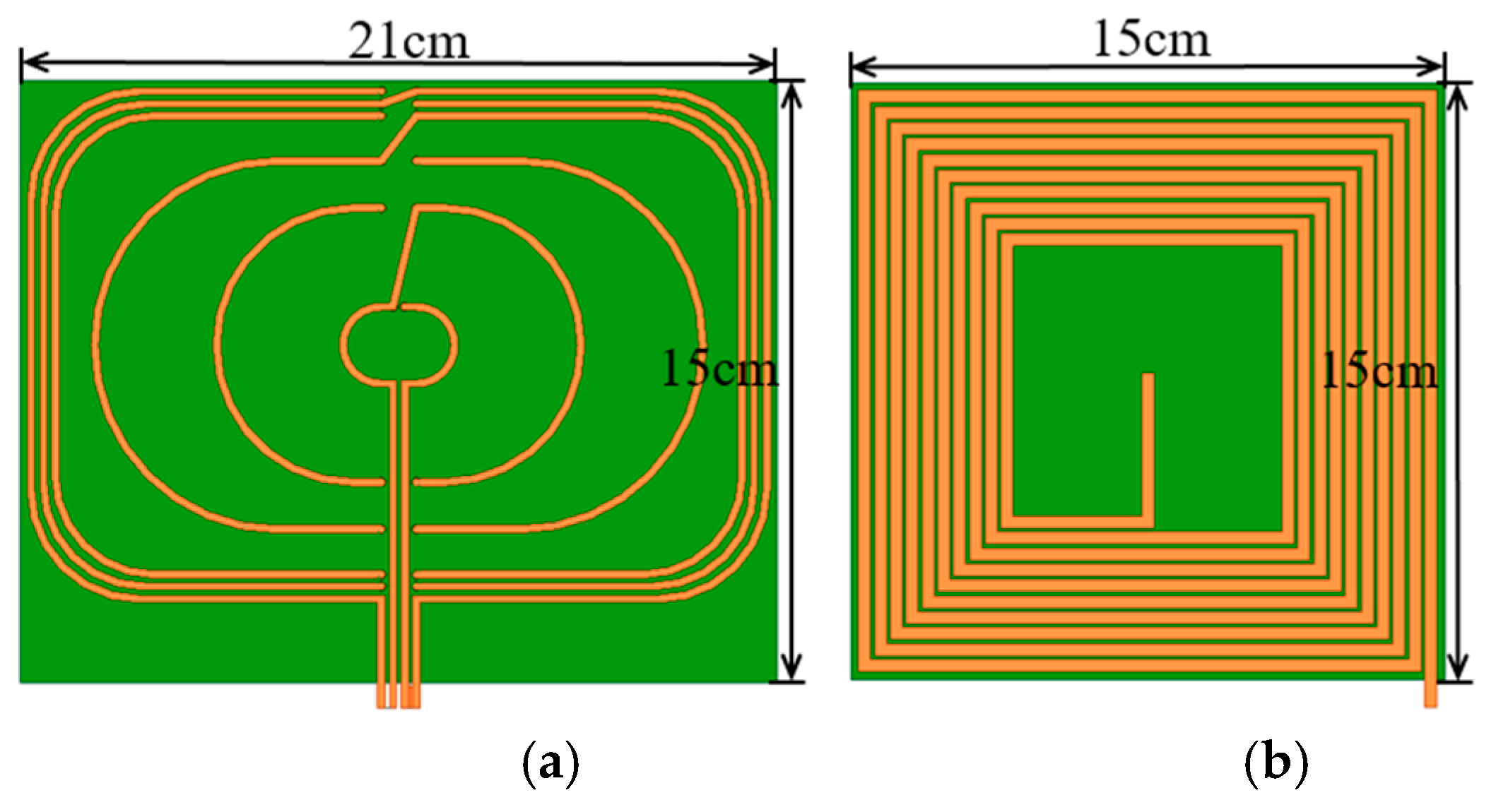
2.3. Analysis of MTM-Enhanced WPT System

A practical model for WPT systems with MTM slabs is proposed and shown in Figure 4. The model of the MTM slab is established using lumped circuit parameters, in which RL is the resistance of the load and ω is the operational angular frequency.
According to Kirchhoff’s Law, the circuit equation is given by (3), where ω 0 is the operation frequency of the WPT system, ω 1 is the resonance frequency of both transmission and receiving coils, and ω M is the resonance frequency of MTMs. Assuming ω 1 = ω 0 , the system efficiency η can be calculated by using (4). Substituting (3) into (4), one finds that the system efficiency is related to ω M and Q M . In other words, ω M and Q M are the key parameters influencing the efficiency of such MTM-enhanced WPT systems.
[ R 1 s 0 0 0 R M 0 0 0 R 3 L ] [ I 1 I M I 3 ] + j [ L 1 ω 1 ( ω 0 ω 1 ω 1 ω 0 ) ω 0 M 1 M ω 0 M 13 ω 0 M 1 M L M ω M ( ω 0 ω M ω M ω 0 ) ω 0 M M 3 ω 0 M 13 ω 0 M M 3 L 3 ω 1 ( ω 0 ω 1 ω 1 ω 0 ) ] [ I 1 I M I 3 ] = [ U s 0 0 ]
η ( ω M , Q M ) = P o u t P i n = I 3 2 R L I 1 U s .
In order to obtain the maximum power efficiency of MTM-enhanced WPT systems, we designed an optimization algorithm by turning ω M . Q M varies only ω M because LM and RM are fixed when the shape of the MTM unit is determined. As for the relative permeability of the MTM slab, it is exactly related to ω M and Q M when the parameters of the WPT system is settled. Therefore, the optimization goal and restrictions are as follows:
Max η s . t . Re ( μ r ) a , Im ( μ r ) b
where a and b are the controllable limitations. The optimal solution can be acquired using optimization algorithms such as genetic algorithm (GA) or particle swarm optimization (PSO) to solve this problem. After calculation, we obtain the optimal ω M which can be tuned by adjusting the additional capacitor in the MTM slab, and then the efficiency of the WPT system with the MTM slab reaches its maximum value. It should be pointed out that, the optimization result is dependent on the setting of limitations. In particular, the parameter b that represents the loss of MTMs needs to be practical, so the results can be verified by experiments.

3. Experimental Verification

A prototype MTM-enhanced WPT system is developed to verify the proposed model. First, the MTM units are designed and fabricated, as shown in Figure 5. The size of the MTM unit is 20 mm × 20 mm × 1.6 mm. Two reverse spirals, each with seven turns, are printed on both sides of the FR4 substrate and connected by a via and a lumped capacitor. The MTM units are then arranged as a two-dimensional slab, as is shown in Figure 5b. The lumped impedance parameter L e f f of an MTM unit is about 4.89 μH and F = 0.37, correspondingly according to simulation results.
A WPT system resonating at 6.78 MHz is then established, shown in Figure 6. An A4WP spiral power transmit resonator is used as the transmission coil (Tx). In order to eliminate the influence of parasitic parameters, a metal spiral is designed as a receiving coil (Rx), as shown in Figure 7. Both coils are printed on PCB and adjusted to resonate at 6.78 MHz. A signal generator and an amplifier are used as the excitation. An impedance matching circuit is connected between the source and Tx. A 50 Ω resistor is loaded on the receiving coil.

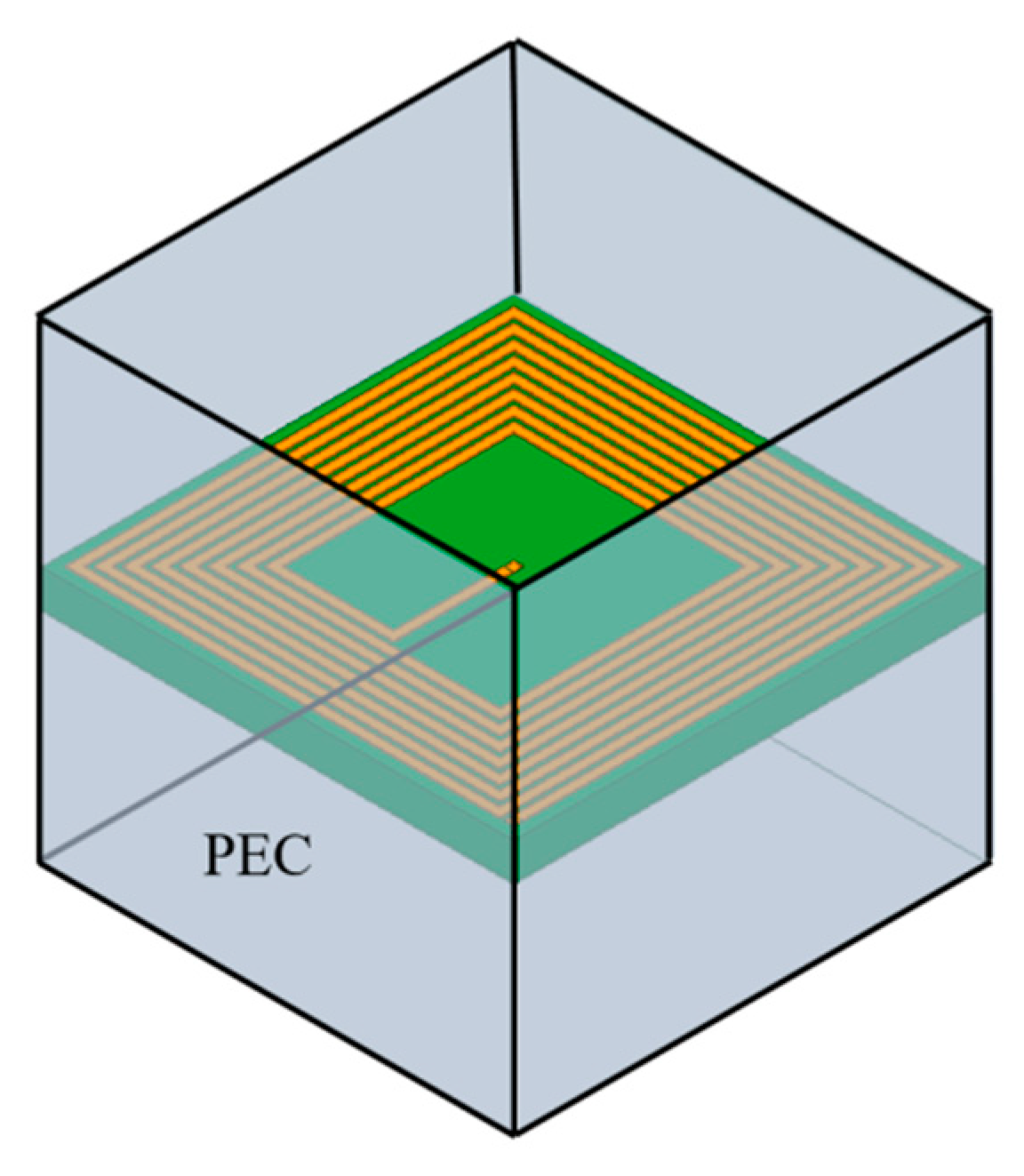
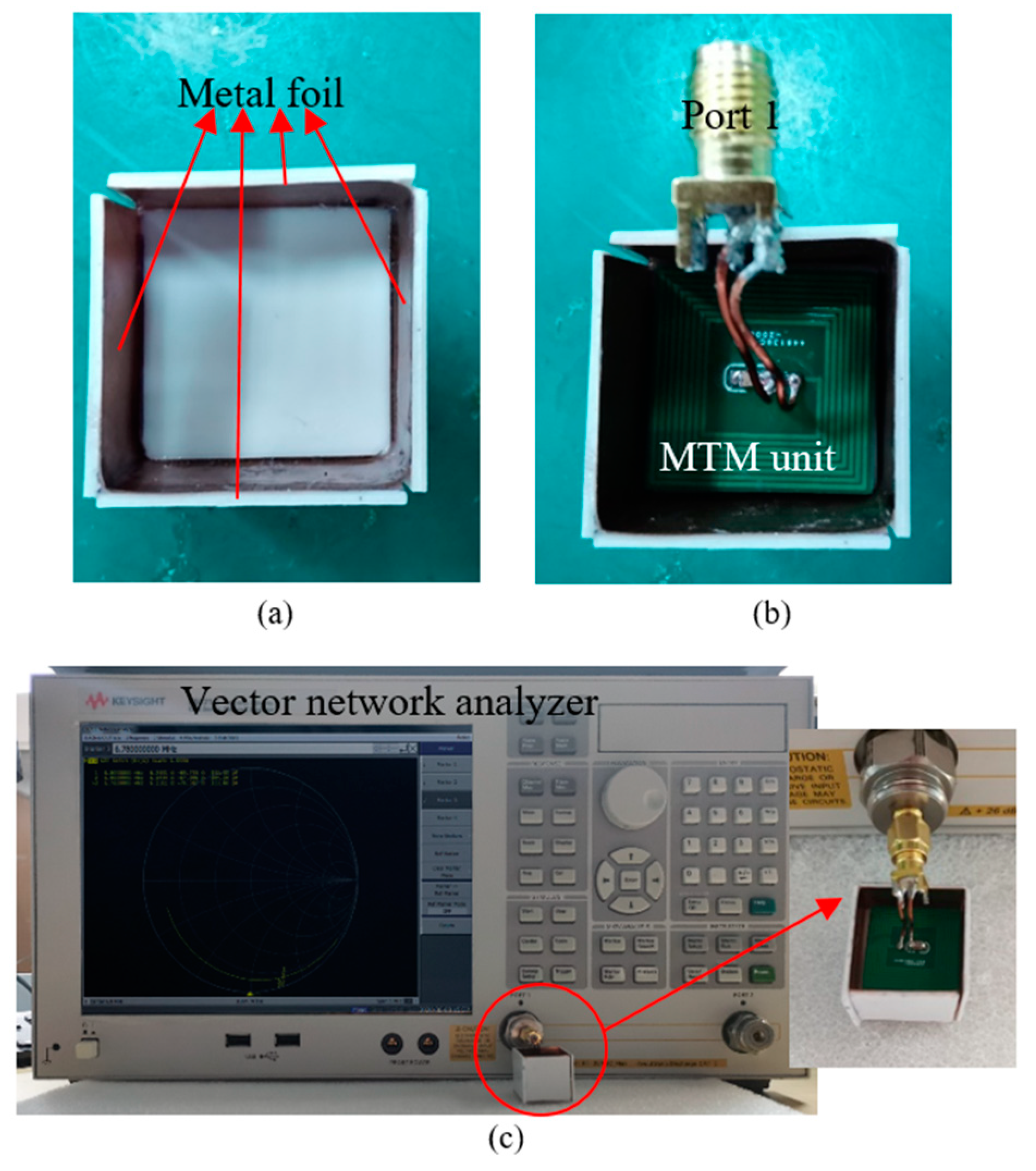
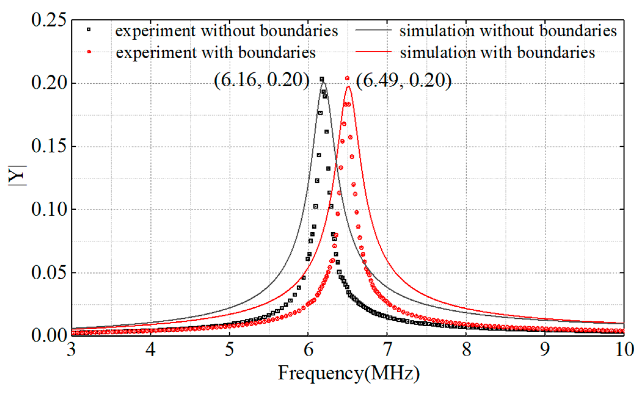
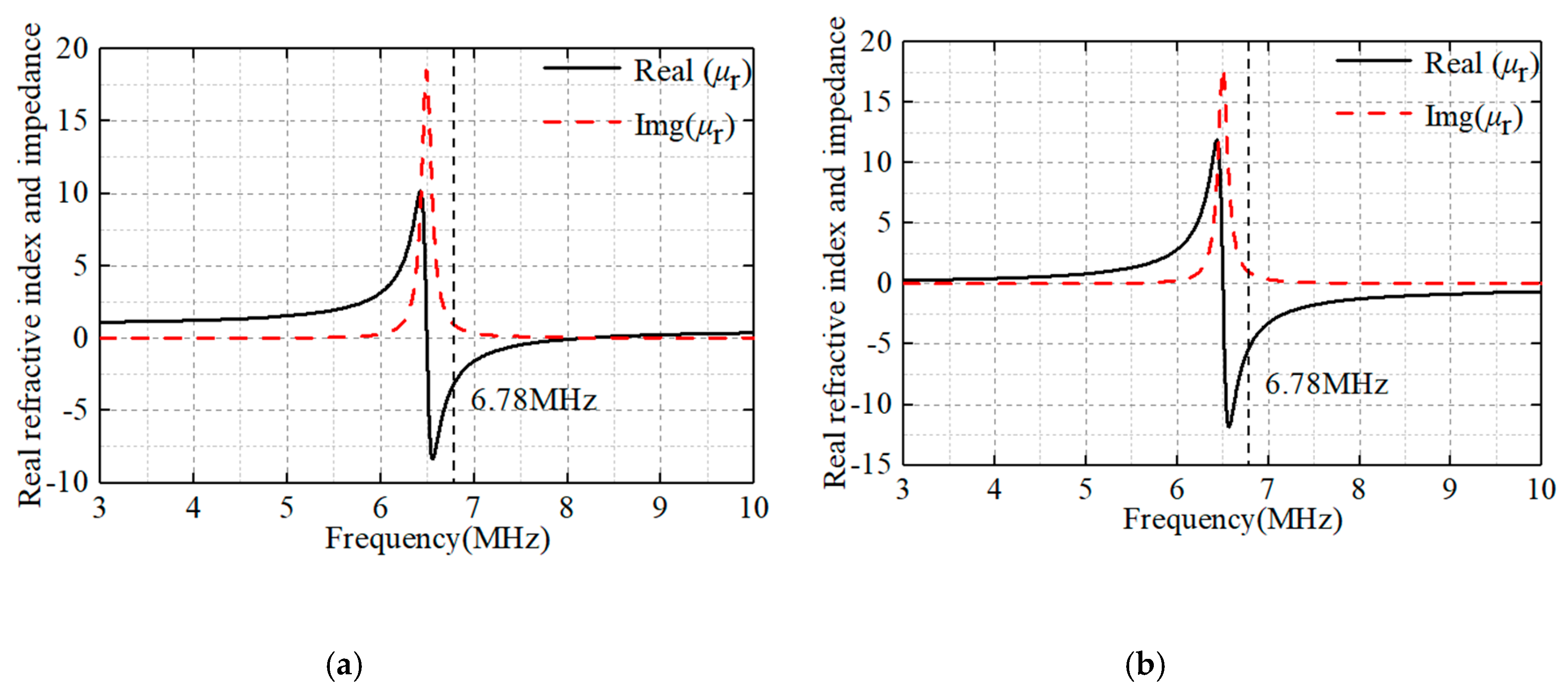
3.1. Permeability Measurement

In order to get the characteristics of the MTM slab, the relative permeability of the fabricated MTM is measured. Firstly, the genetic algorithm with the optimization goal and the restrictions presented in chapter 2 is used to find the optimal efficiency of the WPT system. The parameters of the system are shown in Table 1. The optimized result is f M = 6.5 MHz. By tuning the capacitor in MTMs, the resonance frequency of the MTM slab ( ω M ) is changing as well. It is important to decide the lumped capacitance of each unit in the MTM slab according to the optimal resonance frequency. However, since ω M is influenced by the surrounding units, it is complicated to obtain ω M by calculation, and ω M is also difficult to be tested in experiments. Therefore, an experiment is designed to imitate the periodic boundaries around an MTM unit. A lumped port is located at the interface of the metal spiral, and 4 PEC boundaries are added around an MTM unit shown in Figure 8a, which corresponds to the simulation setting as presented in chapter 2. According to [40], a piece of metal foil is used as the PEC boundary which surrounds an MTM unit to form a cubic test box. As shown in Figure 8b, port 1 of a Vector Network Analyzer is connected to the lumped port of the MTM unit for excitation and testing.
The Y-parameters is obtained after adding a 135 pF lumped capacitor in the proposed MTM unit, and is showed in Figure 9. It is obvious that the MTM slab resonates at 6.49 MHz with the lumped capacitor, whereas the MTM unit without boundaries resonates at 6.16 MHz. It can be seen that the resonance frequency predicted by the experimental method is in good agreement with the simulation result. Since the utilization of copper foil introduces power loss, the quality factor obtained by the experiment has a deviation from the simulation result within tolerance.
Once the ω M and Q M has been obtained, the relative permeability of the MTM slab is calculated and shown in Figure 10. The MTM slab resonates at 6.49 MHz, and the real part of relative permeability is negative at 6.78 MHz. Moreover, because of the power loss from copper foil in the experiment, the imaginary part (represents the loss of MTMs) of the experimental results is slightly bigger than the simulation results. This result is also consistent with the formula ω = L C . According to the experiment and simulation results, the effective inductance of an MTM unit is 4.9 μH. Because of the interaction between MTM units, the resonance frequency of the MTM slab is difficult to decide, so experimental verification is essential.

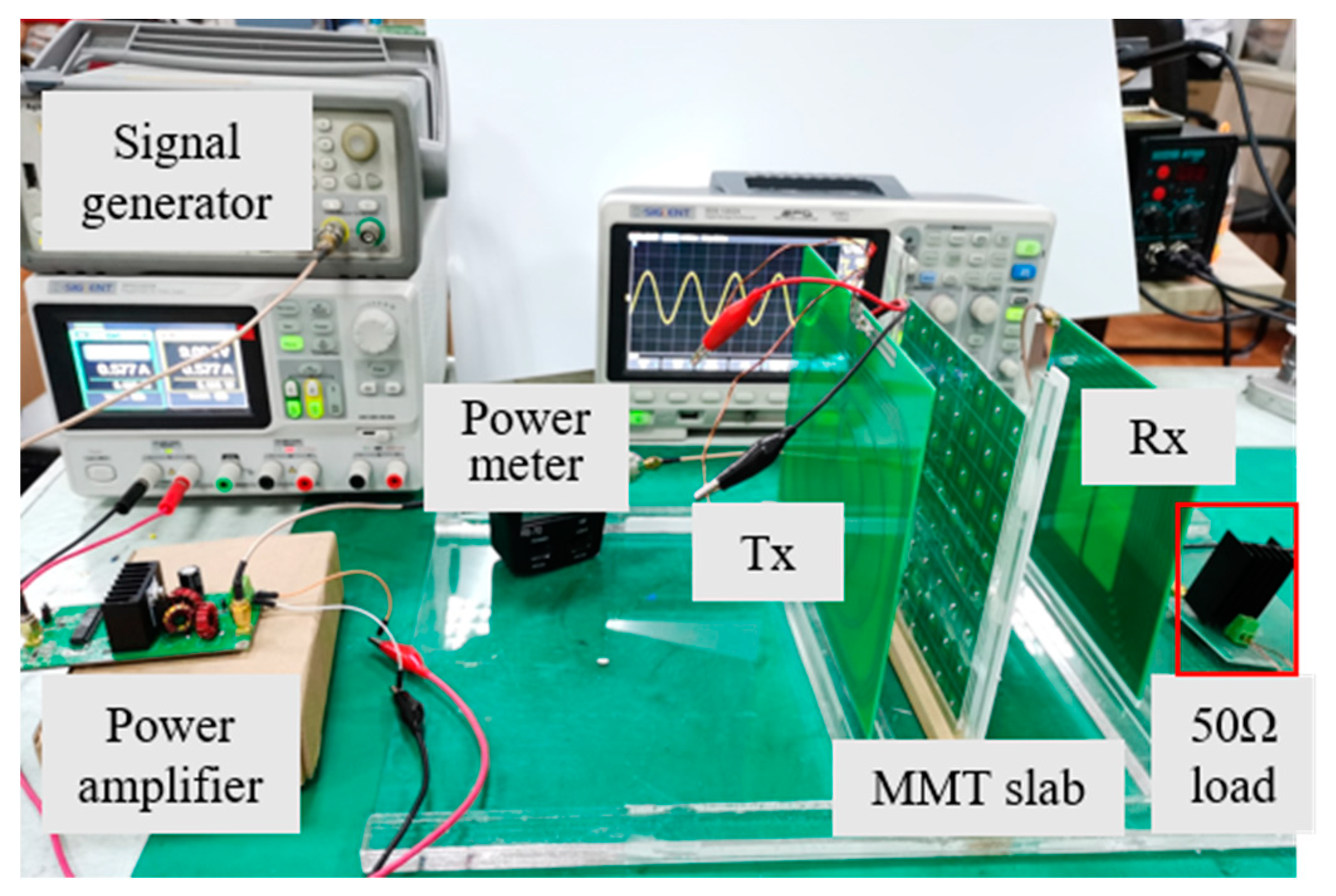
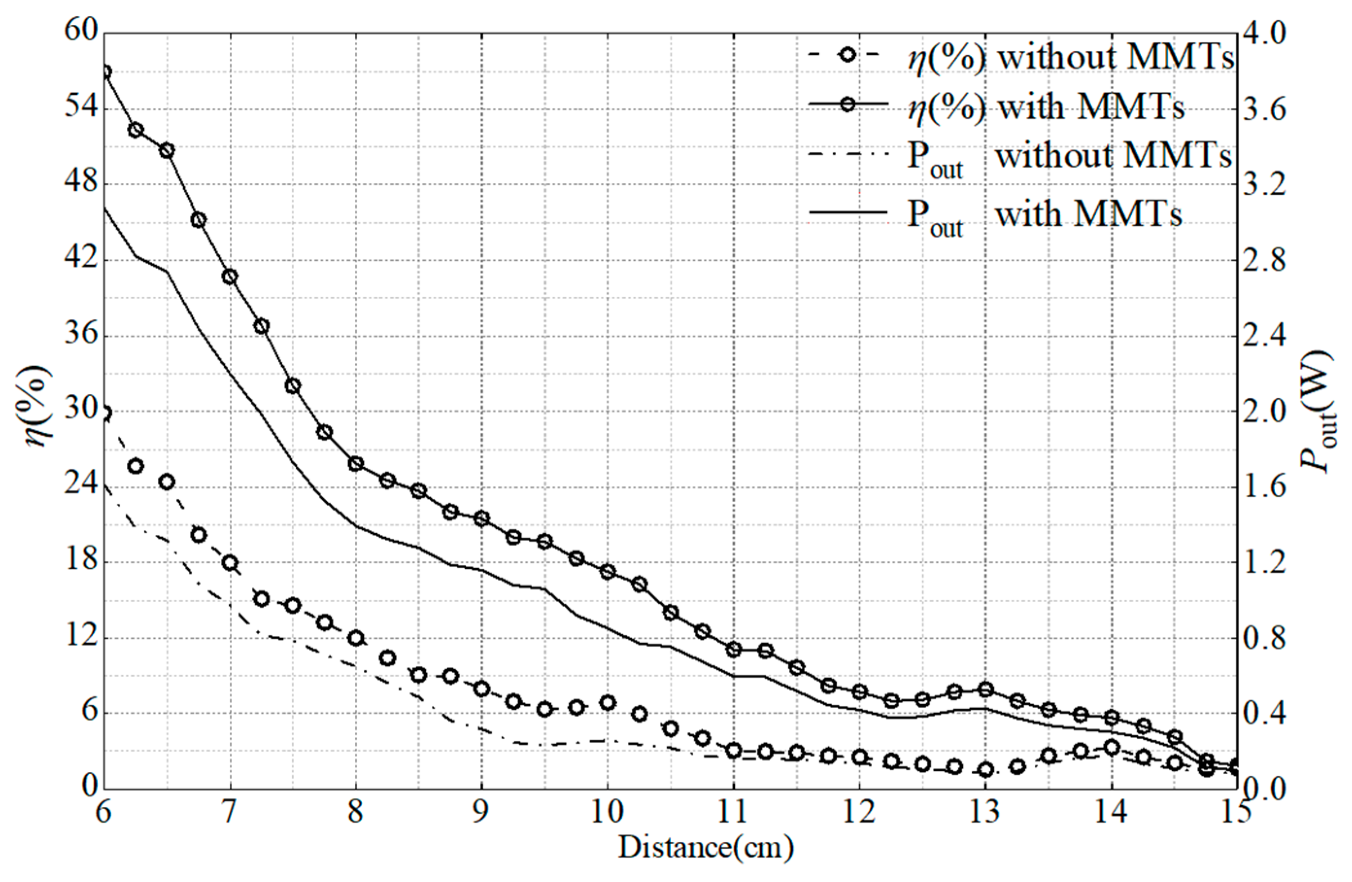
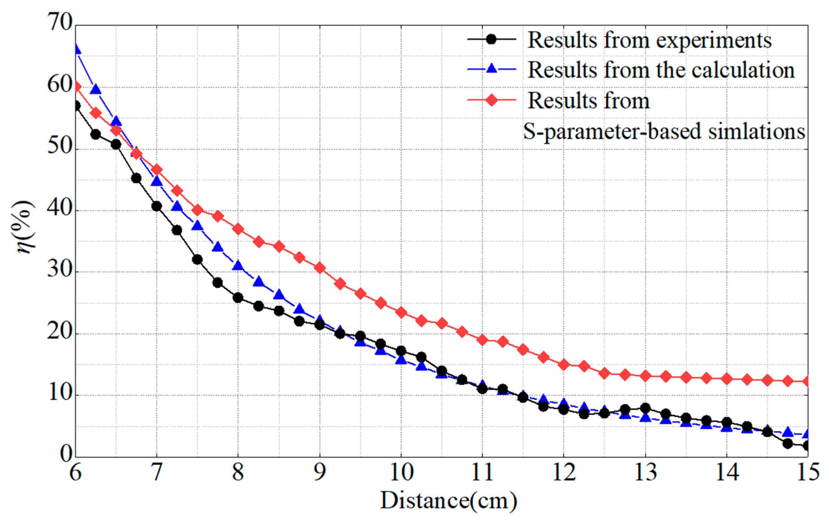
3.2. Experimental Verification of the MTM-Enhanced WPT System

After obtaining the characteristics of the MTM slab, the MTM-enhanced WPT system is established to verify the proposed model. According to the optimization results, when the f M is 6.5 MHz, the power transfer efficiency of the system is 26.4%. The efficiency of the system without MTMs is 8.6% according to (4). The efficiency of the WPT system has increased by 17.8% in theoretical analysis. Nevertheless, the coupling coefficients in this calculation are obtained by magnetic field simulation, which is difficult to measure and sensitive to external disturbances, and this inevitably results in the deviation in the experimental measurements.
To verify the calculation results, the experimental transmission efficiency of WPT is calculated by (4). The input power is measured with a power meter, and the output power is calculated through the measurement of the output voltage. The designed MTM slab is added to the system afterwards and the parameters are the same as the simulation settings.
First, when the operation frequency of the system changes, the variation of power transfer efficiency is shown in Figure 11. The distance between transceiver coils is 15 cm, and the MTM slab is placed 4 cm away from the Tx. The experimental results show that when the MTM slab is tuned to 6.5 MHz, the optimal working frequency of the system is 6.78 MHz. This is consistent with the previous simulation and numerical optimization results. Experimental results also demonstrate that the efficiency of the system is 18.2% when the distance between coils is 10 cm. Afterwards, the position of the slab is fixed and the distance between the transceiver coils is changed in the range of 5–20 cm. The variation of system efficiency with distance is shown in Figure 12. After adding the MTM slab, the transmission efficiency of the experimental WPT system has been greatly improved by about 10% at the transmission distance of 10 cm. Because of the loss in the input signal amplifier, the experimental results are slightly smaller than the results from optimization and theoretical calculations.
In order to verify the accuracy of the proposed practical model, we compared the power efficiency results with experimental results and the high-frequency calculation results (in which efficiency is obtained by measuring S-parameters) and the comparison is made in Figure 13. The power efficiency of the WPT system with the MTM slab is calculated by |S21|2 (S21 is the positive transfer factor. At radio frequency, |S21|2 is usually used to represent the positive energy transfer.), and the results from the proposed model are calculated by (4). It is clearly shown that the results from the proposed practical model have much-improved accuracy than those obtained from the S-parameter method. Furthermore, the S-parameter-based simulation has rather high requirements on the computer performance and is extremely time-consuming.

4. Discussion

The approximations and uncertainties of the proposed model are clarified here. Studies on magneto-inductive (MI) waves have pointed out that the existence of MI waves may add considerably to the losses of the MTMs [41]. Therefore, in MTM-enhanced WPT systems, the losses will cause a drop in system transmission efficiency. This is also the main reason for the disparity between experimental results and theoretical results. However, incorporating MI theory into the MTM-enhanced WPT system would incur complicated expressions and complex results. According to [41], the expression of two-dimensional (or even three-dimensional) MI waves involves various factors under different conditions. In order to solve this problem, we simplified the MI theory and kept the “practical model” concise and the error was controlled under a permissible level, which makes it much more convenient to be applied in practice.
As the analytical method in high-frequency applications usually utilized the S parameter to represent the system efficiency, the efficiency obtained using lumped parameters in this paper cannot be compared directly with previous results. The higher efficiency shown in Figure 13 is owing to different reference standards of efficiency.
As for the future development of the researches on MTM-enhanced WPT systems, the proposed model can help researchers to clarify the resonance frequency of MTMs and to estimate the transmission efficiency of the system. In addition, as the lumped parameters are adopted in the model, the efficiency of the system can be obtained simply using circuit parameters (voltage and current), without resorting to the expensive device, which works in a demanding environment. The proposal of the model will bring great convenience to the subsequent development of the MTMs-enhanced WPT systems.

5. Conclusions

A practical model for MTMs in low-frequency near field WPT systems is proposed and validated in physical experiments in this paper. According to theoretical analysis, once the structure of an MTM unit is fixed, the characteristics of MTMs is merely determined by its resonance frequency and the quality factor. The resonance frequency can be tuned by the added compensation capacitor of the MTM unit. A circuit model for the MTM-enhanced WPT system is proposed and the power efficiency of the system is concluded in an equation that concerns the resonance frequency and the quality factor of MTMs. An optimization algorithm is utilized to find the optimal efficiency of the WPT system by tuning the resonance frequency of the MTM slab. The experimental results of the proposed model is in good agreement with the theoretical analysis. In conclusion, compared with the former works, the practical model and corresponding optimization procedure provide an accurate and simple way to analyze the MTM-enhanced WPT system in the low-frequency near field.

Author Contributions

J.L. and S.Y. conceived and designed the study; J.L. and Z.G. gave the theoretical and data analysis; J.L. gave the design of metamaterials and wrote the paper; J.Z. and J.L. revised the whole manuscript; J.Z. and H.S. gave the financial support during the research. All authors have read and agreed to the published version of the manuscript.

Funding

This research was funded by the Zhejiang Key R&D Program under Grant No. 2019C01044.

Acknowledgments

The authors would like to thank B. Wei at the Training Platform of Information and Microelectronic Engineering at the Polytechnic Institute of Zhejiang University.

Conflicts of Interest

The authors declare no conflict of interest.

References

  1. International Commission on Non-Ionizing Radiation Protection. Guidelines for limiting exposure to time-varying electric, magnetic, and electromagnetic fields (up to 300 GHz). Health Phys. 1998, 74, 494–522. [Google Scholar]
  2. Veselago, V.G. The electrodynamics of substances with simultaneously negative values of ε and μ. Sov. Phys. Usp. 1968, 10, 509–514. [Google Scholar] [CrossRef]
  3. Li, Z.; Huang, R.; Kong, L. Permeability and resonance characteristics of metamaterial constructed by a wire coil wound on a ferrite core. J. Appl. Phys. 2009, 106, 103929. [Google Scholar] [CrossRef]
  4. Pendry, J.B. Manipulating the near field with metamaterials. Opt. Photon. News. 2004, 15, 32–37. [Google Scholar] [CrossRef]
  5. Pendry, J.B. Negative refraction makes a perfect lens. Phys. Rev. Lett. 2000, 85, 3966–3969. [Google Scholar] [CrossRef]
  6. Alekseev, G.V.; Lobanov, A.V.; Spivak, Y.E. Optimization method in problems of acoustic cloaking of material bodies. Comput. Math. Math. Phys. 2017, 57, 1459–1474. [Google Scholar] [CrossRef]
  7. Shelby, R.A.; Smith, D.R.; Schultz, S. Experimental verification of a negative index of refraction. Science 2001, 292, 77–79. [Google Scholar] [CrossRef] [Green Version]
  8. Pendry, J.B.; Holden, A.J.; Robbins, D.J.; Stewart, W.J. Magnetism from conductors and enhanced nonlinear phenomena. IEEE Trans. Microw. Theory Tech. 1999, 47, 1777–1780. [Google Scholar] [CrossRef] [Green Version]
  9. Leonhardt, U. Optical conformal mapping. Science 2006, 312, 2075–2084. [Google Scholar] [CrossRef]
  10. Engheta, N.; Ziolkowski, R.W. A positive future for double-negative metamaterials. IEEE Trans. Microw. Theory Tech. 2005, 53, 1535–1556. [Google Scholar] [CrossRef] [Green Version]
  11. Wang, B.; Teo, K.H.; Nishino, T.; Yerazunis, W.; Barnwell, J.; Zhang, J. Experiments on wireless power transfer with metamaterials. Appl. Phys. Lett. 2011, 98, 254101. [Google Scholar] [CrossRef] [Green Version]
  12. Urzhumov, Y.; Smith, D.R. Metamaterial-enhanced coupling between magnetic dipoles for efficient wireless power transfer. Phys. Rev. B Condens. Matter 2011, 83, 205114. [Google Scholar] [CrossRef]
  13. Zhao, Y.; Vutipongsatorn, V.; Leelarasmee, E. Improving the efficiency of wireless power transfer systems using metamaterials. In Proceedings of the 10th International Conference on Electrical Engineering/Electronics, Computer, Telecommunications and Information Technology, Krabi, Thailand, 15–17 May 2013; pp. 1–4. [Google Scholar]
  14. Zhao, Y.; Leelarasmee, E. Controlling the resonances of indefinite materials for maximizing efficiency in wireless power transfer. In Proceedings of the International Electrical Engineering Congress, Chonburi, Thailand, 19–21 March 2014; pp. 1–4. [Google Scholar]
  15. Huang, D.; Urzhumov, Y.; Smith, D.R.; Teo, K.H.; Zhang, J. Magnetic superlens-enhanced inductive coupling for wireless power transfer. J. Appl. Phys. 2012, 111, 064902. [Google Scholar] [CrossRef] [Green Version]
  16. Lipworth, G.; Ensworth, J.; Seetharam, K.; Huang, D.; Lee, J.S.; Schmalenberg, P.; Nomura, T.; Reynolds, M.S.; Smith, D.R.; Urzhumov, Y. Magnetic metamaterial superlens for increased range wireless power transfer. Sci. Rep. 2014, 4, 3642. [Google Scholar] [CrossRef] [Green Version]
  17. Ranaweera, A.L.A.K.; Duong, T.P.; Lee, J.-W. Experimental investigation of compact metamaterial for high efficiency mid-range wireless power transfer applications. J. Appl. Phys. 2014, 116, 043914. [Google Scholar] [CrossRef]
  18. Ranaweera, A.L.A.K.; Duong, T.P.; Lee, B.-S.; Lee, J.-W. Experimental investigation of 3D metamaterial for mid-range wireless power transfer. In Proceedings of the IEEE Wireless Power Transfer Conference, Jeju, Korea, 8–9 May 2014; pp. 92–95. [Google Scholar]
  19. Rajagopalan, A.; RamRakhyani, A.; Schurig, D.; Lazzi, G. Improving power transfer efficiency of a short-range telemetry system using compact metamaterials. IEEE Trans. Microw. Theory Technol. 2014, 62, 947–955. [Google Scholar] [CrossRef]
  20. Algarin, J.M.; Freire, M.J.; Lopez, M.A.; Lapine, M.; Jakob, P.M.; Behr, V.C.; Marqués, R. Analysis of the resolution of split-ring metamaterial lenses with application in parallel magnetic resonance imaging. Appl. Phys. Lett. 2011, 98, 014105. [Google Scholar] [CrossRef] [Green Version]
  21. Alu, A.; Engheta, N. Pairing an epsilon-negative slab with a mu-negative slab: Resonance, tunneling and transparency. IEEE Trans. Antennas Propag. 2003, 51, 2558–2571. [Google Scholar] [CrossRef] [Green Version]
  22. Wang, G.; Liu, W.; Sivaprakasam, M.; Kendir, G. Design and analysis of an adaptive transcutaneous power telemetry for biomedical implants. IEEE Trans. Circuits Syst. I Reg. Papers 2005, 52, 2109–2117. [Google Scholar] [CrossRef]
  23. Hui, S.Y. Planar wireless charging technology for portable electronic products and Qi. Proc. IEEE 2013, 101, 1290–1301. [Google Scholar] [CrossRef] [Green Version]
  24. Ho, J.S.; Yeh, A.J.; Neofytou, E.; Kim, S.; Tanabe, Y.; Patlolla, B.; Beygui, R.E.; Poon, A.S.Y. Wireless power transfer to deep-tissue microimplants. Proc. Nat. Acad. Sci. USA 2014, 111, 7974–7979. [Google Scholar] [CrossRef] [Green Version]
  25. Mi, C.C.; Buja, G.; Choi, S.Y.; Rim, C.T. Modern advances in wireless power transfer systems for roadway powered electric vehicles. IEEE Trans. Ind. Electron. 2016, 63, 6533–6545. [Google Scholar] [CrossRef]
  26. Elliott, G.A.J.; Raabe, S.; Covic, G.A.; Boys, J.T. Multiphase pickups for large lateral tolerance contactless power-transfer systems. IEEE Trans. Ind. Electron. 2010, 57, 1590–1598. [Google Scholar] [CrossRef]
  27. Wiltshire, M.C.K.; Hajnal, J.V.; Pendry, J.B.; Edwards, D.J.; Stevens, C.J. Metamaterial endoscope for magnetic field transfer: Near field imaging with magnetic wires. Opt. Express 2003, 11, 709–715. [Google Scholar] [CrossRef]
  28. Shamonin, M.; Shamonina, E.; Kalinin, V.; Solymar, L. Properties of a metamaterial element: Analytical solutions and numerical simulations for a singly split double ring. J. Appl. Phys. 2004, 95, 3778–3784. [Google Scholar] [CrossRef]
  29. Sydoruk, O.; Radkovskaya, A.; Zhuromskyy, O.; Shamonina, E.; Shamonin, M.; Stevens, C.J.; Faulkner, G.; Edwards, D.J.; Solymar, L. Tailoring the near-field guiding properties of magnetic metamaterials with two resonant elements per unit cell. Phys. Rev. B 2006, 73, 224406. [Google Scholar] [CrossRef]
  30. Smith, D.R.; Schultz, S.; Markos, P.; Soukoulis, C.M. Determination of effective permittivity and permeability of meteamaterials from reflection and transmission coefficients. Phys. Rev. B 2002, 65, 195104. [Google Scholar] [CrossRef] [Green Version]
  31. Smith, D.R.; Vier, D.; Koschny, T.; Soukoulis, C. Electromagnetic parameter retrieval from inhomogeneous metamaterials. Phys. Rev. E Stat. Phys. Plasmas Fluids Relat. Interdiscip. Top. 2005, 71, 036617. [Google Scholar] [CrossRef] [Green Version]
  32. Li, W.; Wang, P.; Yao, C.; Zhang, Y.; Tang, H. Experimental investigation of 1D, 2D, and 3D metamaterials for efficiency enhancement in a 6.78 MHz wireless power transfer system. In Proceedings of the IEEE Wireless Power Transfer Conference, Aveiro, Portugal, 5–6 May 2016; pp. 1–4. [Google Scholar]
  33. Liu, M.; Liu, S.; Ma, C. A high-efficiency/output power and lownoise megahertz wireless power transfer system over a wide range of mutual inductance. IEEE Trans. Microw. Theory Technol. 2017, 65, 4317–4325. [Google Scholar] [CrossRef]
  34. Das, R.; Basir, A.; Yoo, H. A metamaterial-coupled wireless power transfer system based on cubic high-dielectric resonators. IEEE Trans. Ind. Electron. 2019, 66, 7397–7406. [Google Scholar] [CrossRef] [Green Version]
  35. Gámez Rodríguez, E.S.; Ram Rakhyani, A.K.; Schurig, D.; Lazzi, G. Compact low-frequency metamaterial design for wireless power transfer efficiency enhancement. IEEE Trans. Microw. Theory Technol. 2016, 64, 1644–1654. [Google Scholar] [CrossRef]
  36. Chen, W.-C.; Bingham, C.M.; Mak, K.M.; Caira, N.W.; Padilla, W.J. Extremely subwavelength planar magnetic metamaterials. Phys. Rev. B 2012, 85, 201104. [Google Scholar] [CrossRef] [Green Version]
  37. Gong, Z.; Yang, S. One-dimensional stacking miniaturized low-frequency metamaterial bulk for near-field applications. J. Appl. Phys. 2020, 127, 114901. [Google Scholar] [CrossRef]
  38. Cummer, S.A.; Popa, B.; Hand, T.H. Q-based design equations and loss limits for resonant metamaterials and experimental validation. IEEE Trans. Antennas Propag. 2008, 56, 127–132. [Google Scholar] [CrossRef]
  39. Wiltshire, M.C.-C.; Pendry, J.; Hajnal, J.; Edwards, D.J. “Swiss roll” metamaterials—An effective medium with strongly negative permeability. Compon. Exp. Semin. 2003, 13, 1–10. [Google Scholar]
  40. Cho, Y.; Lee, S.; Kim, D.-H.; Kim, H.; Song, C.; Kong, S.; Park, J.; Seo, C.; Kim, J. Thin hybrid metamaterial slab with negative and zero permeability for high efficiency and low electromagnetic field in wireless power transfer systems. IEEE Trans. Electromagn. C. 2018, 60, 1001–1009. [Google Scholar] [CrossRef]
  41. Shamonina, E.; Kalinin, V.A.; Ringhofer, K.H.; Solymar, L. Magnetoinductive waves in one, two, and three dimensions. J. Appl. Phys. 2002, 92, 6252–6261. [Google Scholar] [CrossRef]
Figure 1. The Swiss roll structure of the metamaterial (MTM) unit. Two reverse spirals on each side of Fr4 substrate.
Applsci 10 08506 g001
Figure 2. The setting of the designed MTM slab with four perfect electronic conductor (PEC) boundaries.
Applsci 10 08506 g002
Figure 3. The admittance parameter (Y-parameter) of an MTM slab. The quality factor Q can be calculated from the graph. Take the resonance frequency fm, and get the high limit frequency fh and low limit frequency fl when the amplitude of Y-parameter drops to 0.707 of itself, then Q = f m / ( f h f l ) .
Applsci 10 08506 g003
Figure 4. The proposed model for the MTM-enhanced wireless power transfer (WPT) system. Mij is the mutual inductance between coils and MTMs.
Applsci 10 08506 g004
Figure 5. The fabricated MTMs, (a) the MTM unit. (b) The MTM slab.
Applsci 10 08506 g005
Figure 6. The proposed experimental system.
Applsci 10 08506 g006
Figure 7. (a) The transmitting coil, (b) the receiving coil.
Applsci 10 08506 g007
Figure 8. The proposed measurement setup (a) The PEC boundaries are made of metal foil with an MTM unit. (b) The MTM unit is added inside the boundaries. (c) Port 1 connects to the vector network analyzer to get the impedance parameters.
Applsci 10 08506 g008
Figure 9. The impedance results of MTMs.
Applsci 10 08506 g009
Figure 10. The relative permeability of the experimental MTM slab. (a) The experimental results. (b) The simulation results.
Applsci 10 08506 g010
Figure 11. Variation of power and efficiency with different frequencies.
Applsci 10 08506 g011
Figure 12. Variation of power and efficiency with different distances between Tx and Rx.
Applsci 10 08506 g012
Figure 13. Comparison of different efficiency results after adding MTM slab in a WPT system.
Applsci 10 08506 g013
Table 1. Parameters of the WPT system.
ParameterValueParameterValueParameterValue
R12.5 Ω L14.7 μ H C1132 pF
R35 Ω L326.7 μ H C320 pF
Rs5 Ω RLeq50 Ω Q241.66
Publisher’s Note: MDPI stays neutral with regard to jurisdictional claims in published maps and institutional affiliations.

