Article

Integrating Virtual Reality and GIS Tools for Geological Mapping, Data Collection and Analysis: An Example from the Metaxa Mine, Santorini (Greece)

by
Varvara Antoniou
1,*,
Fabio Luca Bonali
2,3,
Paraskevi Nomikou
1,
Alessandro Tibaldi
2,3,
Paraskevas Melissinos
4,
Federico Pasquaré Mariotto
5,
Fabio Roberto Vitello
6,
Mel Krokos
7 and
Malcolm Whitworth
8
1
Department of Geology and Geoenvironment, National and Kapodistrian University of Athens, 15780 Athens, Greece
2
Department of Earth and Environmental Sciences, University of Milan Bicocca, Bicocca, 20126 Milan, Italy
3
CRUST-Interuniversity Center for 3D Seismotectonics with Territorial Applications, 66100 Chieti Scalo, Italy
4
Dionysos Satellite Observatory, National Technical University of Athens, 15780 Athens, Greece
5
Department of Human and Innovation Sciences, Insubria University, Via S. Abbondio 12, 22100 Como, Italy
6
INAF–Istituto di Radioastronomia, via Gobetti 101, 40129 Bologna, Italy
7
School of Creative Technologies, University of Portsmouth, Portsmouth PO1 2UP, UK
8
School of the Environment, Geography and Geosciences, University of Portsmouth, Portsmouth PL1 3QL, UK
*
Author to whom correspondence should be addressed.
Appl. Sci. 2020, 10(23), 8317; https://doi.org/10.3390/app10238317
Submission received: 31 October 2020 / Revised: 20 November 2020 / Accepted: 23 November 2020 / Published: 24 November 2020

Abstract

:

Featured Application

The paper combined the exploitation of multimodal digital techniques, focusing a novel methodological approach aimed at integrating Immersive Virtual Reality (IVR) for visualization and data collection, followed GIS analysis, in the geological application field.

Abstract

In the present work we highlight the effectiveness of integrating different techniques and tools for better surveying, mapping and collecting data in volcanic areas. We use an Immersive Virtual Reality (IVR) approach for data collection, integrated with Geographic Information System (GIS) analysis in a well-known volcanological site in Santorini (Metaxa mine), a site where volcanic processes influenced the island’s industrial development, especially with regard to pumice mining. Specifically, we have focused on: (i) three-dimensional (3D) high-resolution IVR scenario building, based on Structure from Motion photogrammetry (SfM) modeling; (ii) subsequent geological survey, mapping and data collection using IVR; (iii) data analysis, e.g., calculation of extracted volumes, as well as production of new maps in a GIS environment using input data directly from the IVR survey; and finally, (iv) presentation of new outcomes that highlight the importance of the Metaxa Mine as a key geological and volcanological geosite.

1. Introduction

Three-dimensional (3D) models of mines that depict the floor, walls and benches provide the basis for several types of mining management and safety applications, including slope stability assessment and monitoring, rock mass assessment, environmental assessment and volume calculations. Common techniques for mine mapping include standard survey techniques using Global Navigation Satellite System (GNSS) and electronic total stations, Terrestrial Laser Scanning (TLS) and more recently photogrammetric approaches based upon Unmanned Aerial Vehicle (UAV) surveys.
Standard survey approaches are typically used for mine surveys; however, they do present difficulties when mapping large or complex sites, and can be time consuming and, therefore, expensive [1]. By comparison, TLS is a rapid technique for generating dense point cloud measurements of mine faces; however, the measurement quality is strongly dependent on the scanning conditions, including the scan configuration, surface geometry and reflectivity [2] and they often require repeat surveys from different vantage points for a complete model of the site. As TLS is a line-of-sight instrument, high cliffs or rock faces that exhibit complex morphology can result in occlusions and data shadows in the final surface model that must be removed during post-processing [3,4]. Drone or UAV photogrammetric-based surveys involve a digital photography collection from a flying UAV platform; these images have the characteristics of large overlap areas between sequential images, multiple viewing angles as the drone passes over the site and high ground resolution [1,5]. Mine surveys using UAV are advantageous in that they allow surveys of vertical rock faces to be combined with standard horizontal UAV surveys and ground-based photography, allowing a complete model to be created from photography taken with different orientations and scales [3,6].
For small simple mine sites, traditional survey techniques are cost-effective for quarry face mapping, but as the survey area gets larger or more complex, TLS or UAV techniques become more effective. It is a trade-off between the time taken for mission planning, accurate positioning of Ground Control Points and photogrammetric post processing of UAV data and the number of survey locations required, and time taken for a TLS survey of a mine. For large complex quarry or mine sites, UAV is the most effective mapping approach [3]. While these two approaches differ significantly, TLS provides high accuracy but is time consuming, while UAV is good for surveying large or complex sites, the joint use of UAV-based photogrammetry and TLS, whereby the photogrammetric approach is supplemented with additional input data from TLS, is increasingly being used to provide an accurate surface model of the quarry or mine [1].
In the present work, we wish to highlight the effectiveness of integrating different techniques and tools for better surveying and mapping, in a mine in a volcanic area, where parts of relevant outcrops are inaccessible or dangerous (e.g., [7,8,9]). In order to do this, we use an Immersive Virtual Reality (IVR) approach as designed by Tibaldi et al., (2020) [10] and integrated it with Geographic Information System (GIS) analysis for better mapping and assessment of geological features (e.g., [11,12]), as highlighted in the conceptual workflow for this paper shown in Figure 1. For Virtual Reality (VR) software, a brand-new software presented here for the first time called GeaVR was used, while for GIS software, a commercial one, called ArcGIS Pro was selected.
The key site selected for the application of this integrated approach is the Metaxa Mine, located in the southwestern part of Santorini Volcanic Complex, Greece (Figure 2a,b). This is a well-known volcanological site where mining of pumice took place up until 1984. The mine is now abandoned, providing the opportunity to characterize it as a full-fledged, open-air geological museum, suitable for the study and recording of volcanic products of the largest eruption occurred in Santorini in the last 10,000 years (Minoan eruption), and one of the largest of its kind on Earth [13,14,15,16]. Every year, students from all over the world use this site for learning, due to the presence of the famous Late Bronze Age (LBA)-section located in the western part (Figure 2c) of the mine, where almost all volcanic phases of the Minoan eruption are exposed. The mine is characterized by steep cliffs up to 15 m in height, inaccessible to classical fieldwork and data collection; and is subject to almost continuous rock falls and debris flows that make approaching the mine faces extremely dangerous.
In addition to classical field surveys (e.g., [20,21]), volcanic areas have been studied by high-resolution, remotely captured images, Orthomosaics and Digital Surface Models (DSMs), especially using unmanned aerial systems (UASs), also known as drone or Unmanned Aerial Vehicles (UAVs), which have high resolution imaging capabilities and an ability to map steep to vertical slopes (e.g., [22,23,24,25,26,27]). Following the drone survey, UAV-captured images are combined with Structure from Motion (SfM) photogrammetry techniques [28,29,30,31] to derive the ortho-mosaic imagery and digital surface model. Data collection and GIS analysis using these high-resolution models enable significant advances in research activity, while allowing user interactivity for mapping and measurement purposes that is still crucial for geologists.
The use of IVR for survey and data collection in volcanic areas allows the user to walk within an area and around outcrops, switch to flying mode to map vertical cliffs, and, more importantly, map features and take measurements in the same way as when working in the field. The VR scenario we used is based on the creation of high-resolution, scientifically correct (i.e., referenced and scaled) and real-world 3D Digital Outcrop Model (DOM), as firstly suggested by Gerloni et al., (2018) [32] and successively improved by Krokos et al., (2019) [33]. In both cases, UAV-based Structure from Motion photogrammetry techniques are used to build the real-world based VR scenario.
In addition to the above, we demonstrate the importance of collecting data in IVR and further elaborate their usage in a GIS environment. Virtual reality (VR) has been integrated with GIS for some time within the academic and industrial communities over the last 30 years.
A variety of spatial analysis software programs are available for handling a wide range of spatial problems, beginning with approaches for describing spatial objects with quite complex analyses and 3D visualization. GIS has proven to be the most sophisticated system that operates with the largest scope of objects (spatial and semantic) and relationships and provide means to analyze them while at the same time being able to intergrade data from many different resources (e.g., [34,35]). Specifically, the current research in 3D GIS is mostly focused on topological models, frameworks for representing spatial relationships and 3D visualization (e.g., [36,37,38,39]).
Another significant area of 3D GIS research is devoted to Web applications. GIS and Virtual Reality (VR) are applied on the Internet to integrate spatial data visualization, analysis and exploration. Integration takes advantage of each component, and enables the dynamic 3D content to be built, visualized, interacted with and deployed, all on the Web (e.g., [40,41]).
Furthermore, although most GIS-related planning practices and education are still limited to two-dimensional mapping and analysis [42], due to the spread of VR technology, a framework to supplement current two-dimensional GIS education in planning using 3D modeling programs has been already developed.
Nowadays, data collection and integration procedures have become part of the normal scientific workflow and can be supported relatively easily through advanced technology that need not be specialized or expensive. Furthermore, IVR can be an instrumental tool for mapping, as it can provide scientifically valid data that can be further combined, analyzed and processed along with the large amount of data in existing GIS environment using powerful GIS tools.
This paper first focuses on an innovative data acquisition method (combining nadir and oblique orientation images) using as an example the Metaxa Mine in order to construct a high-resolution 3D model (see Section 4). We then construct a 3D Digital Outcrop Model (DOM) and we utilize this to carry out a geological survey of the mine, for data collection in IVR. These data are imported into a GIS environment for analysis (see Section 5). Section 6 presents and discusses a range of new geological outcomes obtained with our approach highlighting the Metaxa Mine as a geosite of world importance in the field of geology and volcanology.

2. Description of Volcanological Site Known as the “Metaxa Mine”

Santorini is one of the most popular tourist destinations in the world, a destination where history meets geology. The name “Strongyli,” due to its geological nature, the renowned “Thira” in honor of the Lacedaemonian commander Thiras and the lesser known “Dirmetzik” are only few of the names given to the island over time. The current name “Santorini” was given by the Franks in the 12th Century as a reference to the church of Santa Irene. No other island has ever been so often documented in myths (Chimera Myth, Talos Myth), archaeological and historical data [43].
Santorini (or Thira) does not consist of a single volcano, but of several volcanic centers, which merged after successive volcanic eruptions [44]. Consequently, the whole island is a wonderful natural laboratory of great scientific, historical and geological interest. The impressive, water-filled caldera, which is one of the largest in the world with dimensions of 11 × 8 km, encompasses the volcanic islands of Palaea (Old) and Nea (New) Kameni [45,46]. The caldera depression was created after a major eruption, during which the volcanic dome collapsed as a result of the rapid emptying of the magma chamber [47]. The active volcanic centers of Palaea and Nea Kameni, along with the rest of the islands of Santorini (Thira, Thirasia and Aspronisi), the Christiana volcanic islands in the southwest and the Kolumbo submarine volcano in the northeast (Figure 2a), have long been the focus of international interdisciplinary research (geology, archaeology, history, oceanography and biology).
The uniqueness and significance of Santorini is related to the active volcano, which counts 2.5 million years of history and belongs to the modern Aegean Volcanic Arc. During the last 350,000 years, 12 violent volcanic eruptions have occurred, at least four of which caused the caldera collapse of the volcanic edifice [44]. The latest major eruption, also known as “Minoan Eruption,” took place approximately 3600 years ago, during the Late Bronze Age [48]. The most significant outcome, in terms of the island’s geomorphology, was the collapse of a massive part of the Strongyli island and the creation of the modern caldera. It was one of the most crucial eruption of historical times, during which 30–40 km3 of magma were erupted and the height of the explosive column is estimated to have reached 36–39 km into the stratosphere. Tons of ash and volcanic material buried the prosperous prehistoric city of Akrotiri in 1500 B.C. The rapidly spread, superheated volcanic flows caused a tsunami, which is estimated to have reached a height of 30 m and struck the coast of Crete, contributing to the decline of the Minoan civilization [15]. The sheer magnitude of the eruption affected not only the Cyclades and the Aegean but also contributed significantly to a climate change around the globe. Since then, the volcano of Santorini has erupted several times, constantly changing the morphology of the island through the creation of new landscapes and demolition of former ones [49]. Within the flooded caldera, a volcanic dome emerged from the seafloor, representing the base of the present-day Kameni islands [50]. The latest lava emission and occurrence of volcanic smog took place in 1950 on Nea Kameni, the newest land in Santorini and Europe.
The Metaxas mine, located in Thira Island, is a model geosite as it is an experiential destination that can be visited all year long, has a systematic geological record and a long pumice mining history, while several recent initiatives exist for deploying innovative digital virtual and augmented reality technologies.
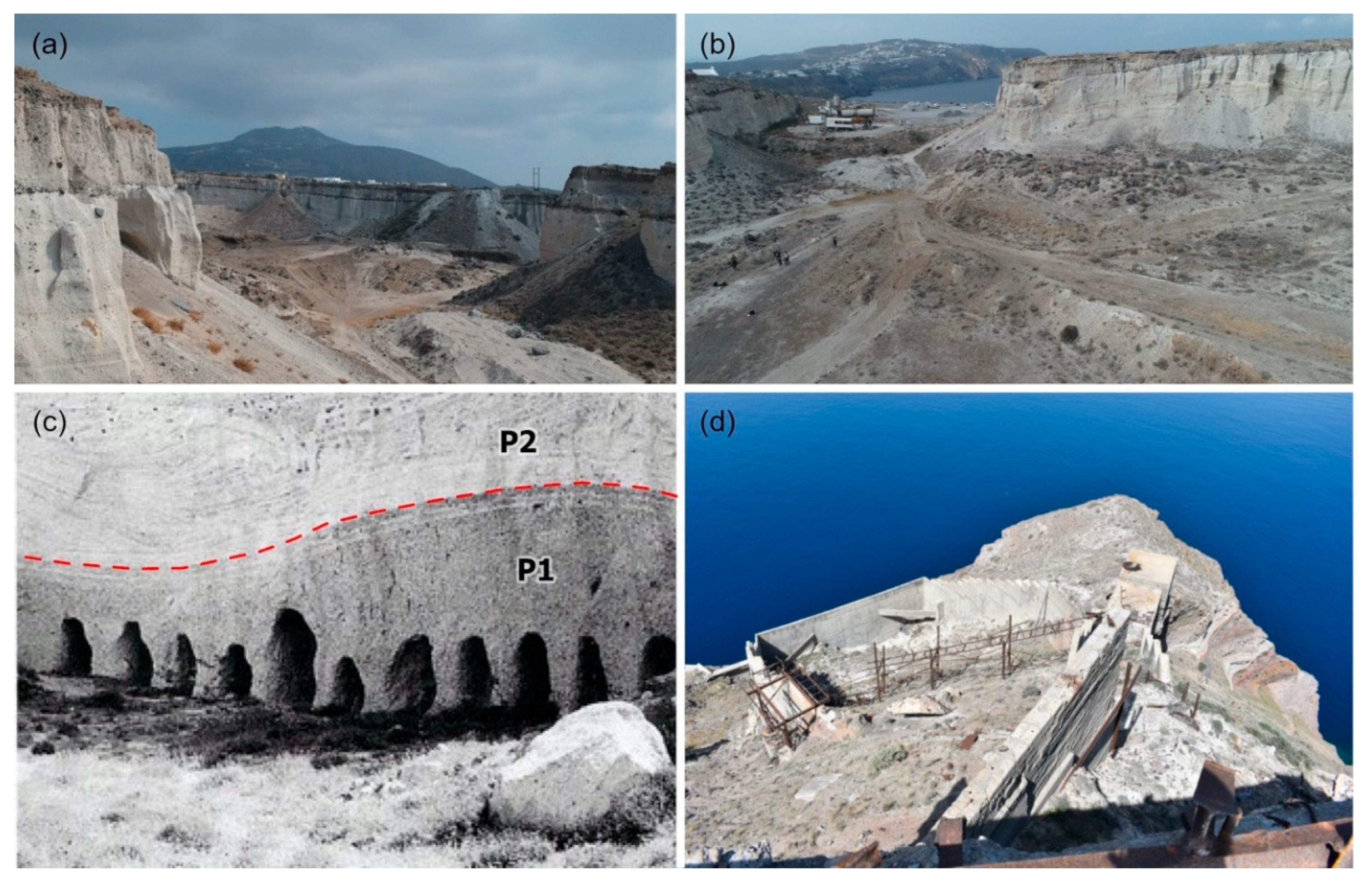
Being an abundant mine, the landscape presents an asymmetrical morphology, with almost vertical and overhanging cliffs, debris flow deposits and anthropogenic interventions, while its floor is heterogeneous, scattered with small hills corresponding to covered excavation materials (Figure 3a,b).
Along the vertical slopes of the mine, and especially in the famous section previously mentioned, Tibaldi et al., (2020) [10] quantified the pumice layers of the Minoan eruption: the 1.03-m-thick layer of the precursory explosion (P0); the 2.58-m-thick Plinian pumice fall (P1); the 12.68-m-thick pyroclastic surge deposits (P2), at the lower part of which we can distinguish a fine-grained bedset; and lastly, the 4.98-m-thick ignimbrite of the fourth phase (P4), rich in lithic clasts. The low-temperature pyroclastic-flow deposits of the third phase (P3) is missing here (Figure 2c).
About 4.5 million m3 is estimated to have been extracted from the entire area of the Metaxa mine using a unique process called “cut” [51,52] (Figure 3c). This was done by opening in parallel covered galleries around 1.2–1.5 m wide and 2 m high, in a direction perpendicular to the slope and at a depth of 10–15 m. The opening was done with simple tools and the distance between the galleries was typically 3.5–5 m. Transportation of the mined material was done by rail wagons to the so-called “ruler” (or storage tank) and from there on a conveyor belt loaded into ships (Figure 3d). The mortar, of which the strength is even increased when construction occurred with sea water, had been used in several ancient construction projects, such as the great fortification in Crete during the Cretan Revolution, but also in earlier periods. The Metaxa Mine represents a crucial moment in the history of the Earth, being an important witness of the natural and geological processes that currently shape its surface. Moreover, it is an industrial heritage site, where volcanic history became part of Santorini’s economic development, as the extraction of pumice materials gave income opportunities to local populations. For these reasons, its protection and popularization need to be promoted at a cultural and touristic level.

3. Immersive VR and GeaVR Visual Discovery Framework

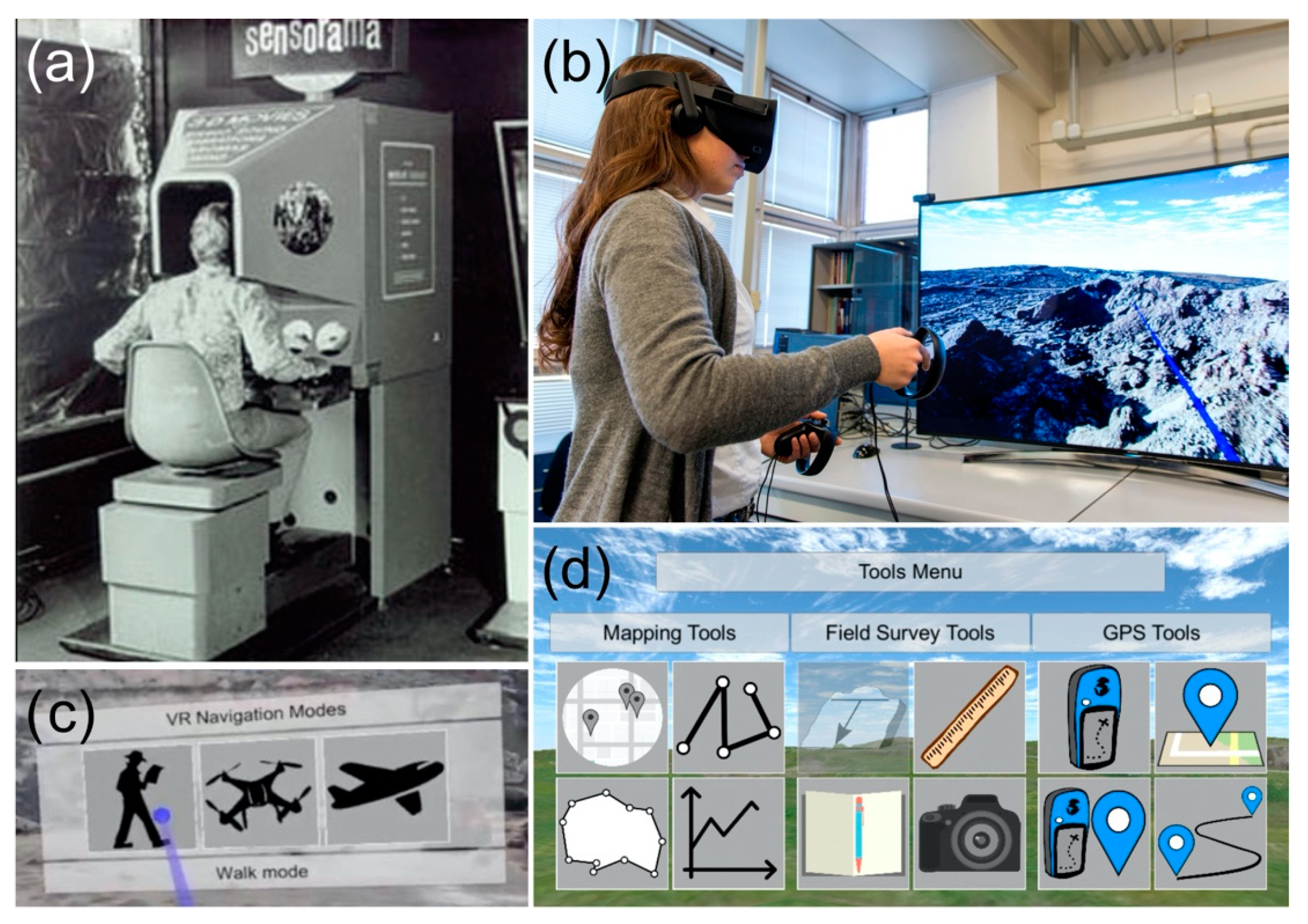
Virtual Reality (VR) was first introduced in 1962, as a computer-generated simulation of a three-dimensional environment that can be interacted with in a seemingly real way by persons using special electronic equipment, such as headsets with screens inside or gloves fitted with sensors. This earliest VR system was provided by Morton Heilig, US Patent #3,050,870; this system was named “Sensorama” (Figure 4a) and it supported multi-sensory technology. Nowadays, following the definition from Choi et al., (2016) [53], VR can be distinguished in two types: non-immersive and fully immersive VR (IVR). The former displays 3D models on a computer screen or mobile device without using any head-mounted displays, typically referred to as 3D visualization (e.g., [54]). The latter enables greater interactivity, through VR headsets and goggles (e.g., Figure 4b). The technical maturity reached in the evolution on modern game engine platforms, combined with lower costs of VR devices now allow creation of immersive VR environments in a variety of application contexts such as teaching and learning in education, professional training in industry, scientific research and public outreach [55,56].
The IVR approach has been fully developed for Earth Science by Tibaldi et al., (2020) [10], in the framework of the Italian Argo3D (https://argo3d.unimib.it/) and European Erasmus+ 3DTelc (http://3dtelc.lmv.uca.fr/) projects; in addition, Gerloni et al., (2018) [32] and Krokos et al., (2019) [33] gave a contribution over time, providing scientists with novel navigation mechanisms for exploring outcrops in a fully immersive way, offering the possibility to also interact and collect measurements, thus replicating real world field activities.
The resulting software is named GeaVR, which is an offline-based Visual Discovery Framework developed with the Unity (https://unity.com) game engine, employing an Oculus Rift (https://www.oculus.com) as a head-mounted VR device, allowing earth scientists to navigate, interact and perform measurements in their own immersive VR scenarios, based on photogrammetry outputs (e.g., 3D Digital Outcrop Models) as well as freely available Digital Elevation Models (DEMs) and Digital Terrain Models (DTMs). Both technologies are widespread and provide good examples for developing software such as the one presented here. GeaVR can be relatively easily ported to other game engines or headsets. Through GeaVR, it is possible to perform complex geological investigations and massive quantitative data collection into scalable models, focused on: surface attitude, topographic profile (e.g., considering the 3D surface), mapping of points of interest, lines, polygons, pictures, etc. All the available tools allow users to export scientifically correct data collected during a IVR session, offering the possibility to interoperate with external software such as GIS and Google Earth. GeaVR will be made available at https://geavr.eu, for non-commercial use and after registration. GeaVR provides to end users a holistic view of the area of interest (e.g., [32]) by allowing the exploration of specific features from several points of view and at a range of different navigation modes (e.g., Figure 4c) while supplying a toolset to simulate field activities in both onshore and offshore environments (Figure 4d).
In this research, we have built up the ad hoc VR scenario for the Metaxa Mine using photogrammetry approach, to map the different volcanic phases and measure their thickness and also to map debris flows and anthropogenic debris. The outputs from GeaVR software were imported to ArcGIS Pro (https://www.esri.com/en-us/arcgis/products/arcgis-pro/overview) for further processing that included the estimation of the volume of excavated material (see Section 5).

4. DSM, Orthomosaic and VR Scenario Building

Our research started by planning UAV surveys and related pictures collection to build up a 3D tiled model, the Orthomosaic and the DSM for the Metaxa Mine, as can be seen in present days.

4.1. UAV Survey, Pictures and Ground Control Points Collection

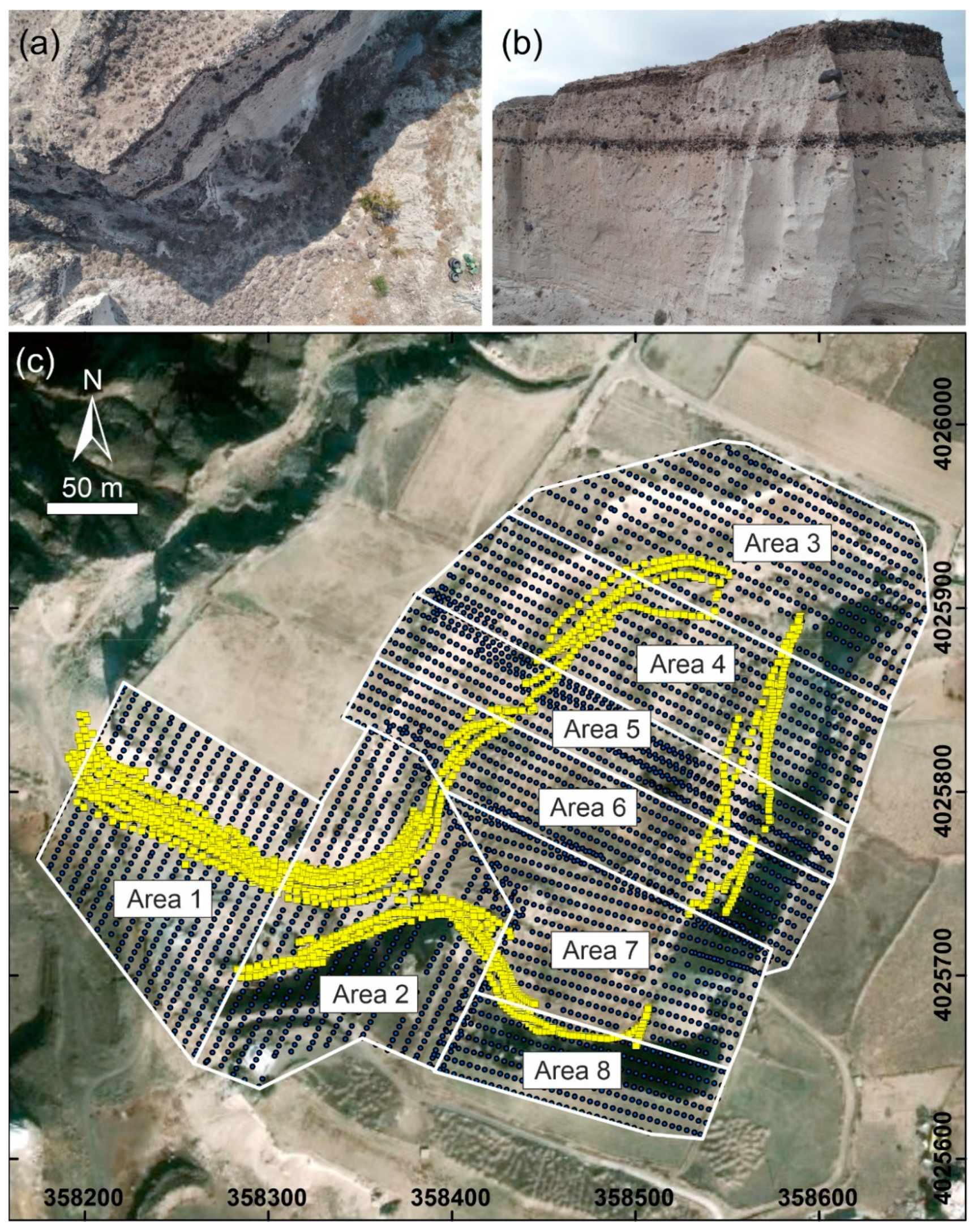
We set out the 3D reconstruction of the Metaxa Mine by applying the SfM photogrammetry techniques; pictures were collected using drone surveys (e.g., [27,57,58]), with the camera oriented both in Nadir and Oblique settings, as shown in Figure 5a,b. In this work, we used the DJI Phantom 4 Pro, a versatile quadcopter equipped with a 20 Megapixels camera and an integrated Satellite Positioning System GPS/GLONASS (referred to the WGS84/Geographic coordinates reference system). Metadata of the collected images are stored in EXIF files (Exchangeable Image File Format), which include information such as shutter speed, apertures, ISO, and GPS coordinates.
The first set of pictures (n = 3896; Figure 5c) were collected with nadir camera orientation (orthogonal to the ground; Figure 5a), following the workflow presented by Bonali et al., (2019, 2020) [27,58], where the flight missions over the target area are designed and managed using the DJI Ground Station PRO (https://www.dji.com/ground-station-pro), a free iPad app for DJI drones’ operations. We set up each single mission, defining the areal extent, flight path direction, flight height (m above the take-off point), camera parameters and pictures overlap, and directly checking data acquisition on the iPad display. The overlap ratio has been set to 90% along the path and 85% in the lateral direction (e.g., [27,32]). Pictures have been captured using the equal time interval mode and using constant flight speed [27,58]. The flight height was set up to 25 m, to reach 1 cm/pixel of ground texture resolution; the flight speed was set up automatically by the software in compliance with all other settings. All the above steps were managed directly in the field. We completed eight flight missions/areas (Figure 5) for this step; each was run using one UAV battery, totaling 2.5 h of flying time; further details are shown in Table 1.
The second set of pictures (n = 1898; Figure 5c) were captured with oblique camera orientation (Figure 5b), to add details to the vertical cliffs of the mine, resulting from excavation processes. In doing this, the quadcopter was manually operated, maintaining a constant speed of about 1–2 m/s, and the pictures were automatically taken every two seconds using the DJI GO 4 app (http://www.dji.com/). The camera was oriented from mostly orthogonal (oblique) to vertical cliffs (between −45° and −70°). This task was performed in four missions, totaling 1.2 h of flying time (details in Table 2).
Finally, we collected 34, uniformly distributed, Ground Control Points to co-register the photogrammetry outputs (3D model, DSM and Orthomosaic) to the WGS84/UTM35 reference system (e.g., [59,60]). This task was performed using Emlid Reach RS© single frequency receivers in RTK configuration (with centimeter-level accuracy), expecting centimetric accuracy (e.g., [61,62,63,64]).

4.2. Photogrammetry Processing for UAV-Captured Pictures

The 3D model for Metaxa Mine has been produced using Agisoft METASHAPE photogrammetry software (http://www.agisoft.com/), a commercial SfM software characterized by a user-friendly interface and clear workflow with a reasonable price of the educational license and, much more importantly, good quality of the resulting SfM-derived models [28,29,30]. Processing has been performed using the Agisoft Cloud beta service, where the virtual machine is equipped as follows: CPU-32 vCPU (2.7 GHz Intel Xeon E5 2686 v4), GPU 2 × NVIDIA Tesla M60, RAM 240 GB. Hereunder we describe the steps we adopted to produce the 3D tiled model, DSM and Orthomosaic, following a common workflow designed by previous authors [27,65,66]; we also applied new settings suggested in the Agisoft METASHAPE forum, especially to work with Oblique pictures. In any case, before running the workflow, all pictures acquired with Oblique orientation need to be prepared. As shown in Figure 5b, the sky shows in the picture; therefore, it had to be masked and removed by processing: it can be masked directly in Agisoft METASHAPE, after uploading all pictures, using Magic Wand and Intelligent Scissors tools.
The first step consisted of aligning all pictures using low quality settings and generic preselection. In this step, focal length and photo dimensions were automatically computed by the software and then used for the subsequent calibration of the core parameters of the camera (principal point coordinates, lens distortion coefficients).
In the second step, we added all GCPs to the model to obtain a scaled and georeferenced point cloud to improve the accuracy of the final models. Then, the images were realigned using high accuracy settings and 15,000 and 150,000 as limit values for Tie and Key points settings, respectively. Values for Tie and Key points were improved following the discussion on Agisoft METASHAPE forum regarding alignment (https://www.agisoft.com/forum/index.php?topic=3559.0), where the resolution of the camera is also considered for these settings; in addition, Tie Point accuracy has been changed and set to 0.5 pix. A new Sparse Cloud resulted from this processing (Figure 6a).
The third step consisted of a Dense Point Cloud building (Figure 6b): in this case, it was generated using the aggressive depth filtering and medium quality settings, so the sparse point cloud generated in Step 2 was mandatory. In addition, we applied the “Filter by Confidence” tool to remove noisy points from the dense cloud, resulting from matching of Nadir and Oblique pictures. Especially, we removed some points in the range of 0–3 from the vertical cliff, and we removed all points which did not relate the final area for the model we wanted to obtain.
The fourth and fifth steps were both based on processing on the Dense Cloud and on the production of the DSM, the Orthomosaic and the 3D Tiled Model, necessary to work with immersive Virtual Reality. DSM was generated from the dense point cloud using default settings, and successively, the Orthomosaic was produced using the corresponding DSM. Both have been built using the reference system WGS84/UTM35.
The final step consisted of building the 3D Tiled model, which includes both mesh and texture. We suggest using a Medium quality set-up with a tile size of 4096 × 4096 pixels and to export it in Agisoft Tile Archive selecting OBJ file format.
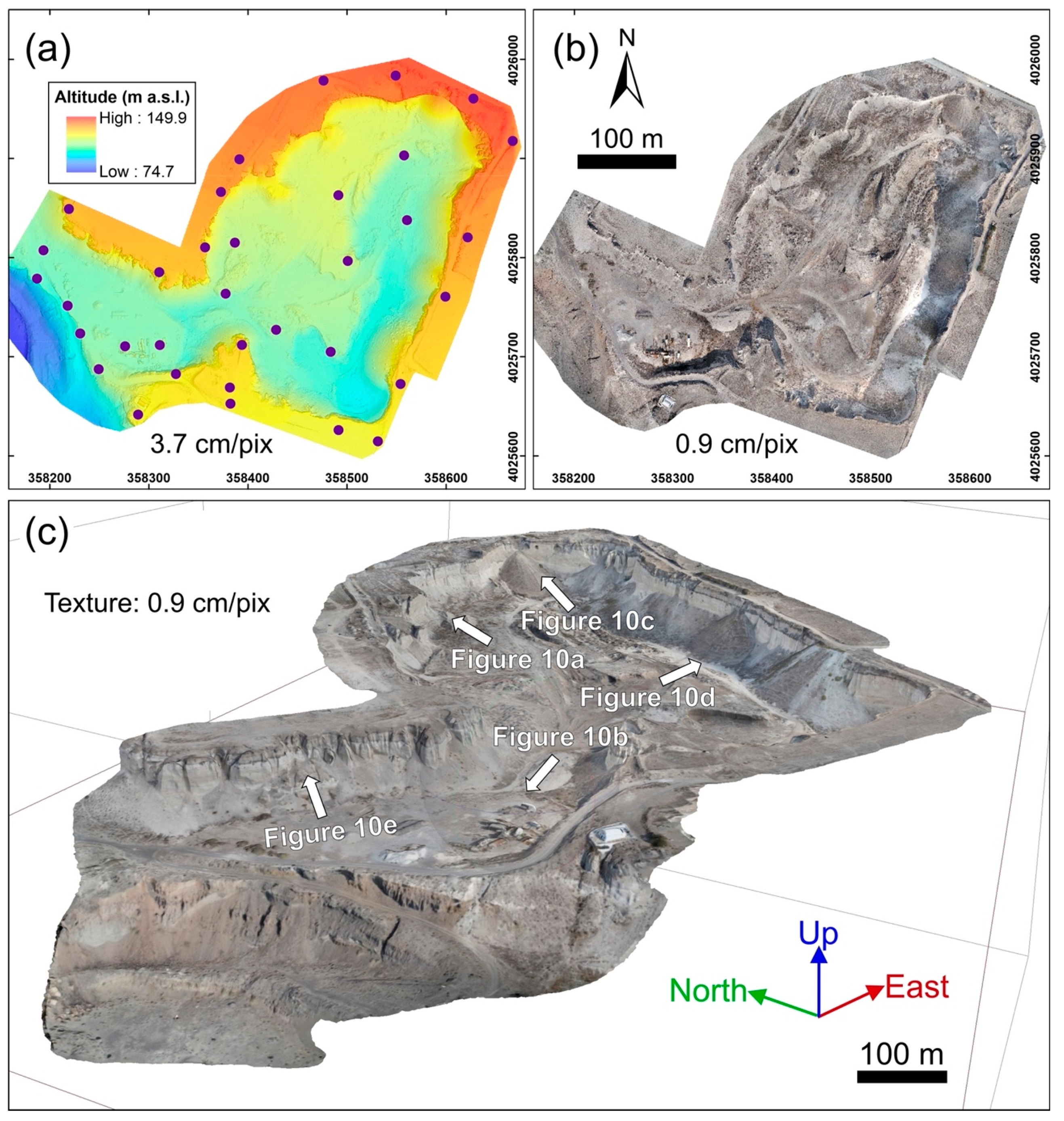
The areal coverage of our study area has an extent of about 520 × 400 m; the surveys were carried out during the early autumn 2018 campaign, during which we collected a total of 5794 photos during a total flight time of 3.7 h. The SfM-derived models regard a high-quality DSM and Orthomosaic (Figure 7a,b), respectively characterized by a resolution of 3.7 and 0.9 cm/pixel, and the 3D Tiled model (Figure 7c) that is characterized by a texture resolution identical to the Orthomosaic. In regard to the processing time, as detailed in Table 3, all outputs were generated in 39.6 h, where the most time-consuming processing were the Alignment process and the 3D tiled model generation.

4.3. Photogrammetry Processing for Aerial-Captured Photos

In order to generate a pre-excavation digital surface model of the mine site, acquired from the Hellenic Military Geographical Service (HMGS) historical archive, as they collected national aerial photos, using KC-I(B)sensor for the whole Greek Territory for military purposes.
As far as the Santorini island complex is concerned, the aerial photogrammetric survey took place on 26 July 1960, a year when excavations had not yet begun, while the area where the Metaxa Mine is located, appears in two aerial photos of 1:30,000 scale (Figure 8a,b). These photos were then scanned by means of a Leica Photogrammetric scanner DSW700 in 1600 dpi having a ground pixel dimension of 0.51 m.
The whole processing to obtain the DSM and the orthomosaic model of the area was made on ERDAS IMAGINE v15 (https://www.hexagongeospatial.com/products/power-portfolio/erdas-imagine). Firstly, inner orientation of the images was restored, using parameters of the lens. Then, six Ground Control Points (GCP) were used to georeference the two images; three were triangulation points recognized on the images, measured with a GNSS receiver in static mode, with 1 cm accuracy in WGS84/UTM35 reference system, and the others were corners of old buildings, recognized at new orthophotos of the area, two of which with 0.5 m accuracy using ortho images with pixel size of 0.2 m and the third one with 2–3 cm estimated accuracy measured with GNSS receiver in RTK mode, for other projects [67]. Respectively, z values were measured according to tide gauge existing in the Port of Thira, having for the triangulation points an estimated accuracy of 3–4 cm and 5–10 cm for the one measured, whereas the rest of the points were estimated through aerotriangulation before being used as ground control points with an error of 0.22 and 0.22 m, respectively.
The alignment had automatically generated 116 Tie points with maximum uncertainty value of 0.666 m, which were used to orthorectify the created model and produce a DSM with a pixel size of 1 m (Figure 8c). The final accuracy of the produced DSM, from the above processing, is estimated to be at 2 m horizontally and 1 m vertically, while the produced orthomosaic has a pixel size of 1 m (Figure 8d,e). In Figure 8e,f the orthomosaic of 1960s stereo images and generated digital surface model of the area are presented.

5. Data Collection in IVR and Following GIS Data Analysis

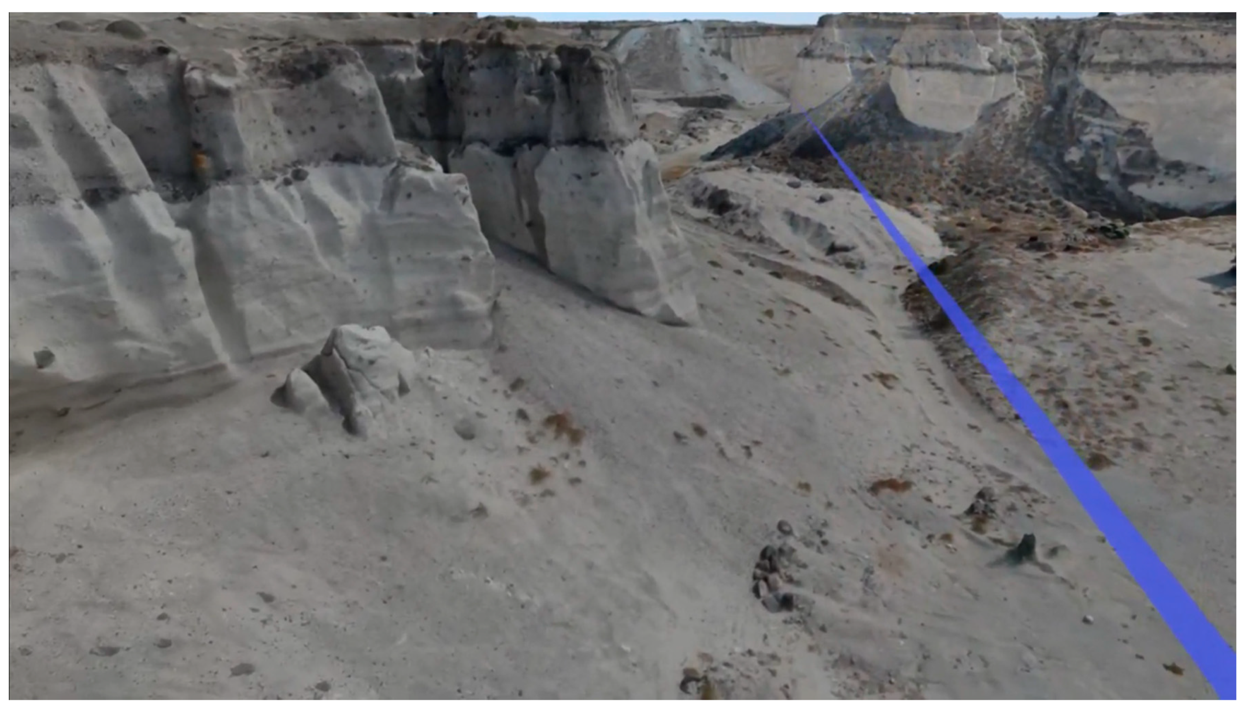
The 3D tiled model resulting from photogrammetry is processed into a form to allow optimized loading at runtime into GeaVR; such a form contains multiple meshes as well as physics calculations. For the same reason, surface texturing files are converted into an optimized format such as Microsoft DirectDraw and DDS surface files. This processing is automatically done using an ad-hoc and drag and drop system, which will be available with GeaVR software. The resulting folder contains all files necessary to load the VR scene to be navigated in IVR, using a user-friendly interface. After the conversion, the produced scene can be loaded (Figure 9) and the first step regarding data collection in IVR is related to the survey of the area, which we tried to explore using all three modes (Figure 4c). Drone modality was finally selected, because it allowed us to rapidly move within the VR scenario, as well as to fly above and around the objects of interest to more effectively map 3D geological features, as shown in Figure 9 and in the following video: https://youtu.be/Mw1c2503qAo.
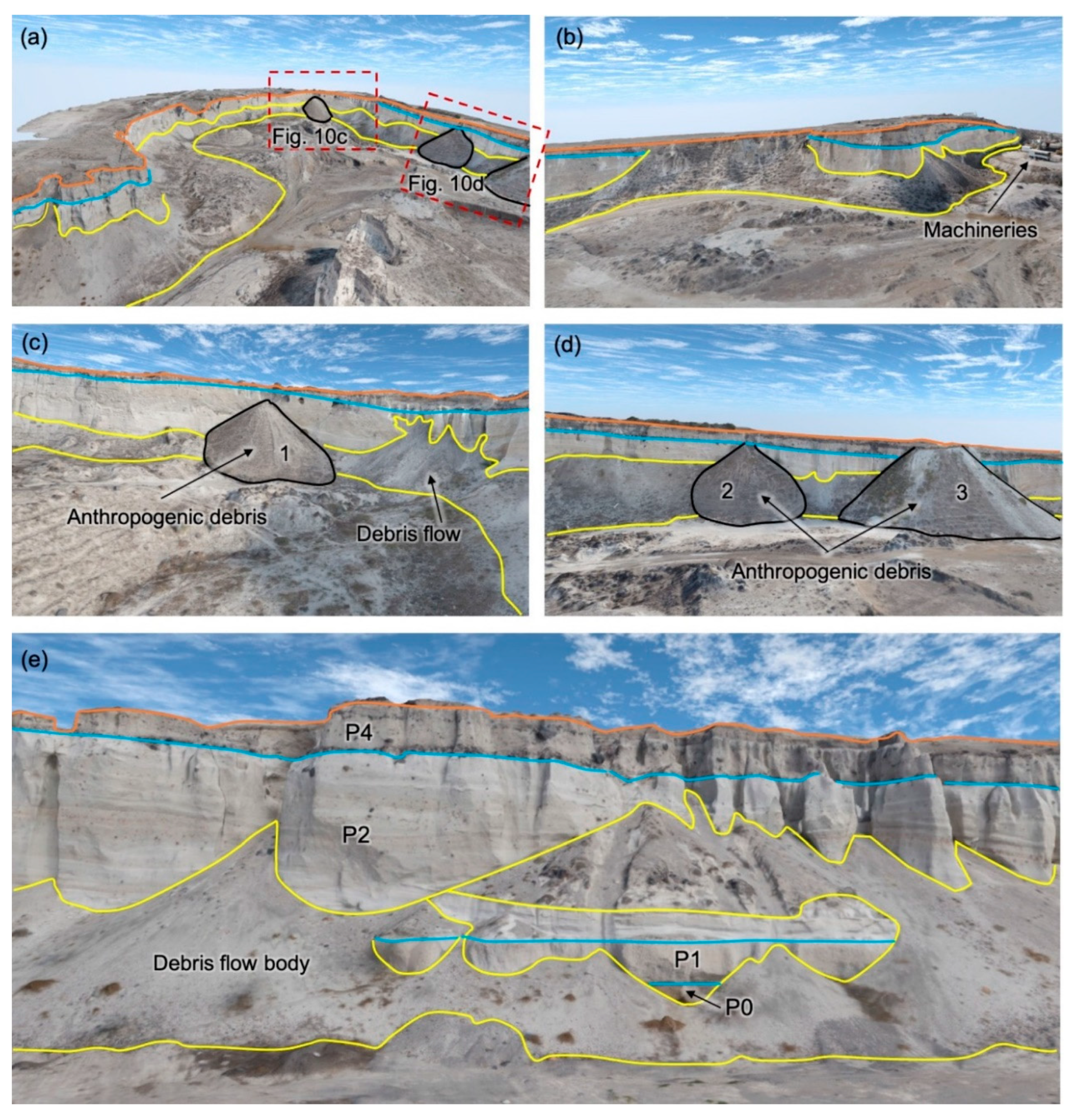
After an overall exploration of the mine to identify interesting geological features that cannot be easily appreciated through conversional means, we came up with a list of possibilities as follows (Figure 10):
  • Upper boundary of excavation in the mine area,
  • Eruption phase boundaries related to the Minoan eruptions, including measurements of their thickness,
  • Areas covered by anthropogenic debris and machineries,
  • Areas covered by natural debris flows.
To perform these tasks, we used the following tools: Camera, Line, Polygon and Ruler (Figure 4d). With the Line tool, the user can trace a line point by point; the Polygon tool can be used to trace a polygon, always with a point-by-point approach (vertices). Both the lines and polygons created are characterized by a unique ID number and x,y,z location that corresponds to the real-world geographic coordinates, and in addition, short textual information, e.g., a brief note and a name, can be added. All lines and polygons can be exported in KML format, to be directly imported in a GIS environment, whereas information about vertices can be exported as a text file, including z values. The Ruler tool provides the distance between two points selected in the scene and the Camera tool captures a screenshot of user’s observation in the IVR scene.
The Line tool allowed us to trace the upper boundary of excavation in the mine area and outcropping boundary between eruption phases P2 and P4 (Figure 10). Although Phase 3 is the only one missing in the mine, the boundary between phases P0, P1 and P2 can only be seen where the famous section is located at the entrance of the mine (Figure 10e), due to extensive debris flows that cover the lower parts of the cliffs.
The Polygon tool allowed us to map and define the areal coverage of anthropogenic debris and machineries, as well as natural debris flows. Considering the level of vegetation that grows on these surfaces we can assume their relative temporal relationship, with 3 being the oldest and 1 the newest (Figure 10a,c,d).
Finally, using the Ruler tool, we quantified the Minoan phases’ thickness at several part of the mine, along the vertical cliff, focusing on P2 and P4 phases that are the most exposed. We collected a total of 80 measurements along the vertical mine cliffs, quantifying, for the first time, the maximum thickness of 17.8 m and of 7.2 m for P2 and P4, respectively. The Camera tool was used to capture several pictures all over the area, with the aim of showing the main characteristic landforms inside the mine (Figure 10).
In addition to the above, we evaluated the overall volume of excavation materials in the area, processing the two digital surface models we obtained in the present work, in ArcGIS Pro, as follows:
First, the SfM-derived DSM was cleaned, removing values that correspond to debris flows, anthropogenic debris and the machineries located near the entrance. The generated raster elevation file was then improved by filling the cleaned part with interpolated values, obtained with the Inverse Distance Weighting (IDW) method, using the Elevation Void Fill tool (Figure 11a).
Second, aerial photo-derived DSM was clipped according to the upper boundary of excavation mapped in IVR, after being converted into a polygon (Figure 11b).
Using the CutFill tool, the two abovementioned final elevation files (focusing within the excavation boundary for both), we produced a new raster that corresponds on the one hand to the common area shared between them and on the other hand only to excavation materials, having an estimated volume of 1,660,141.89 m3 (Figure 11c).
Apart from estimating the overall excavated volume, an effort was made to use the boundary between eruption Phases 2 and 4, which was digitized, for the first time, on a 3D model with the excellent texture resolution of 1 cm/pixel, to create a surface. Outputs (lines and points) from IVR survey, were imported into ArcGIS Pro to first estimate the boundary plane and then the volume of phase 4 (Figure 12). The hypothetical plane created through Topo to Raster tool is flat, with elevations that vary approximately between 105 m to the west and 147 m to the northeast, while dipping towards the south. The estimated total volume of P4 excavation materials rises to 794,386.02 m3.

6. New Outcomes

6.1. New Data for the Metaxa Mine by IVR and GIS Tasks

In this research, data concerning the Metaxa Mine was collected surveying the area in IVR, flying in drone mode within the scene, using GeaVR software as shown in the following video: https://youtu.be/Mw1c2503qAo. Thanks to this approach, we were able to map the entire upper boundary of excavation in the mine, as well as the natural debris flows and anthropogenic debris, and the outcropping boundary between eruption phases (Figure 10). This was accomplished even though the study area is situated along the vertical cliff continuously affected by debris and rock falling, preventing classical field survey.
Of the LBA-phases, Phase 3 is the only one missing in the mine, whereas the boundaries between phases P0, P1 and P2 can only be seen where the famous section is located at the entrance of the mine (Figure 10e), due to extensive debris flows that cover the lower parts of the cliffs. Therefore, only the outcropping boundary between Phases 2 and 4 was digitized, while a new element, the upper boundary of debris flows as well as areas with anthropogenic debris were recognized and digitized with high (centimetric) accuracy.
We measured the thickness of eruption phases wherever this was possible along the cliffs. First, we noticed that the thickness of eruption Phase P4 ranges from 1.7 m to 7.2 m. This wide range of values can be attributed to the different degree of surface erosion. The thickness of eruption Phase P2, as measured in the famous section, presents a value of 12.68 m, whereas measurements all around the mine show values ranging from 7.31 m to a maximum of 17.8 m. The more limited values can be attributed to the extended debris flows that cover the lower parts of the cliffs. The maximum values for both eruption phases are scattered along the southern and eastern cliffs.
Furthermore, by interpolating the digitized boundary between Phases P2 and P4, a surface was generated, which suggests that the boundary presents an increased elevation in a southwest to northeast direction and a dip to the south.
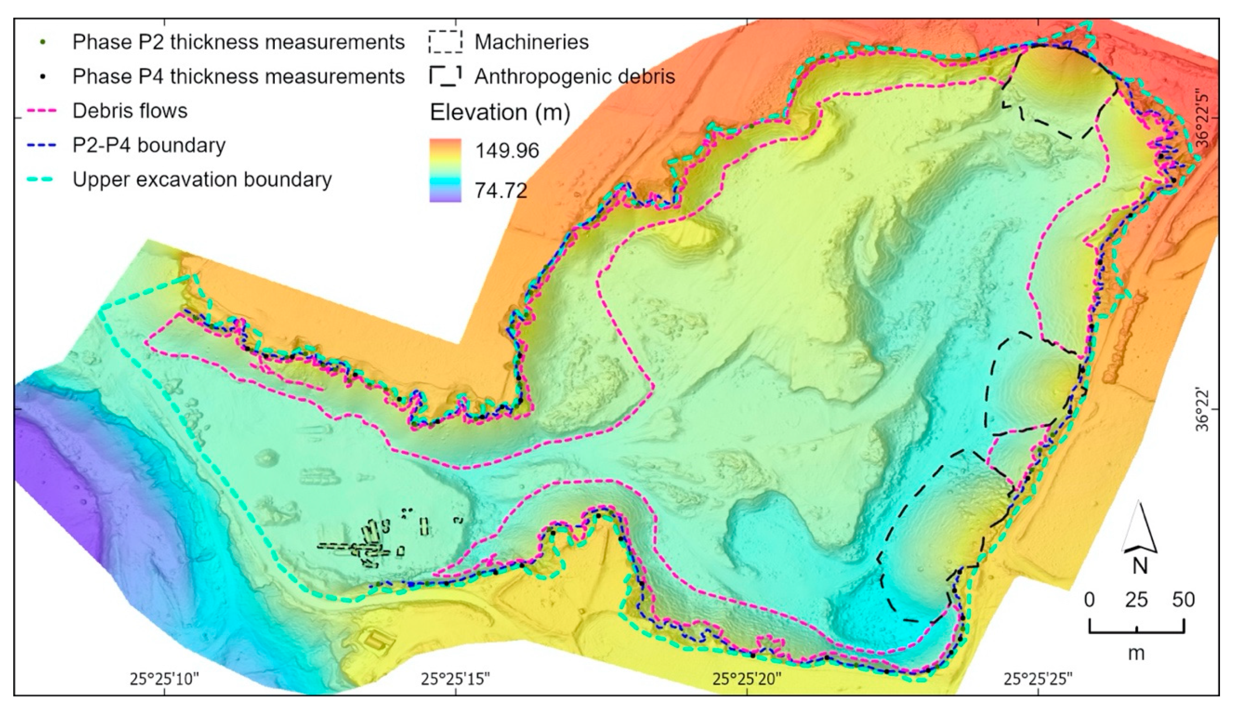
Regarding the volume of excavation material, using two photogrammetry-derived DSMs, one representing the area as it was back in 1960 and one representing the present-day one, we estimated a volume of 1,660,141.89 m3 that corresponds to the northern part of the entire area named the Metaxa Mine (Figure 2b), which is in accordance with the volume estimated by Antoniou et al., (2019) [19] and Tibaldi et al., (2020) [10], who mentioned that about 1.3 million m3 was excavated in the early years of mining from the area left to the famous section, whereas a total of 4.5 million m3 is estimated to have been extracted from the whole area (Table 4). Their estimation was based on a digital terrain model dated in 2018 with a pixel size of 2 cm. Particularly, based on our calculation, the volume of the excavated material that corresponds to Phase 4 was estimated to be approximately 24% of the total studied area. Finally, to present all data collected using the IVR approach, a thematic map was produced summarizing all figures mapped, as well as the location of quantitative measurements (Figure 13).

6.2. The Metaxa Mine as a Fundamental GeoSite

The Metaxa Mine may be considered one essential part of Santorini’s geoheritage, a concept that has been defined in several papers (e.g., [68,69]). Geoheritage is, in turn, tightly related to geological heritage sites, or geosites. These have several characteristics: (i) they are “geological objects or fragments of the geological environment exposed on the land surface, thus, accessible for visits and studies” [70,71]; (ii) they may also be crucial in terms of their social relevance: in fact, they are geological objects that have a scientific, cultural, historical, aesthetic, social and economic value [72]; (iii) they may be quarries, mines, outcrops or individual volcanic landforms [71]; (iv) based on how well-known they are by the scientific community and beyond, they can be of global, national, regional or local relevance [73]; (v) they can be further classified [70] in terms of their appearance (circumscribed sites, such as mines, linear features, such as dykes, or aerially extended features, such as peaks) and their dynamic state (inactive features/processes vs. active ones).
During the last decades, many authors have tried assessing geosites by means of several criteria, such as representativeness, rarity and integrity [62,74,75,76,77], and the degree of scientific knowledge regarding the geosite, attested by published scientific studies [78]. Representativeness is associated with the way in which a geosite may represent the types of geological processes (active or inactive) that can occur on Earth. On the other hand, rarity is related to how a geosite is uncommon/unique at the regional or global level [74]. According to other stu dies [79,80], there are additional values that can be identified and assessed: cultural, economic, aesthetic and educational ones. Among the above, particularly worthy of mention is the educational potential of a geosite, which can be regarded [78] as the combination of the following: didactic relevance (how easily a geosite’s features might be understood by the lay public), safety, accessibility and the present-day exploitation of the geosite for education-related activities (such as guided tours).
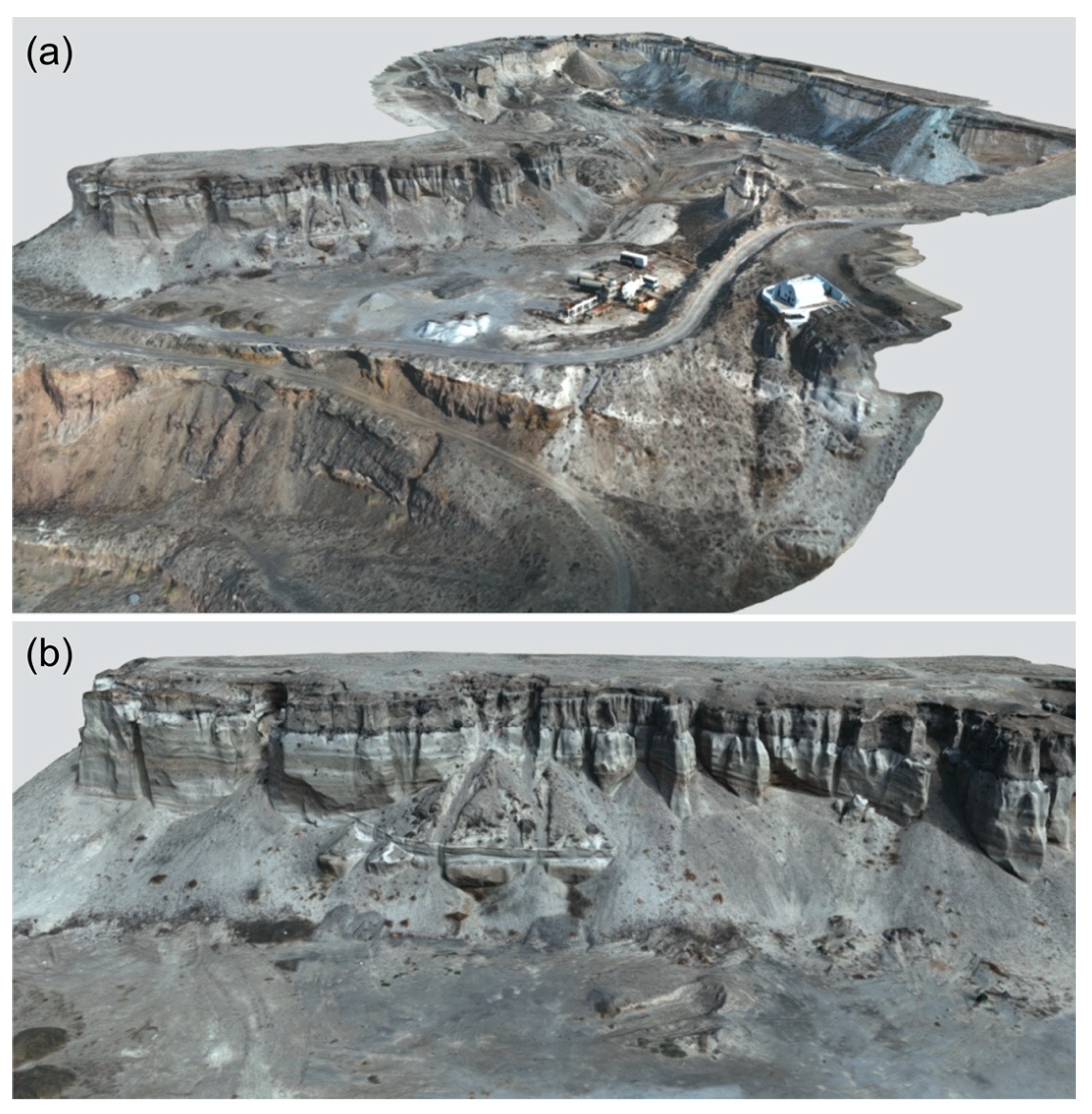
Based on the abovementioned criteria, the Metaxa Mine can be regarded as a geosite in its own right: in fact, most of the above outlined features can be applied to it. Firstly, the mine is rare and unique, as it is greatly representative of one of the most devastating geological events that can take place on Earth: a gigantic Plinian eruption, such as the one that took place here about 3600 years ago. The Metaxa Mine clearly matches the scientific value as well, as the LBA-section has been the subject of extensive research in the past; additionally, in terms of the educational criterium, the Metaxa Mine is an outstanding geosite, as it provides a chance to clearly illustrate to anyone, even those without a geological background, almost all volcanic processes and phases of a classical Plinian eruption such as the “Minoan” one. Again, in terms of the educational value, this geosite has a great educational potential, being easily accessible and suitable for guided tours and educational activities. Finally, the mine has also had economic importance, as pumice was caved here until 1984. The extremely promising educational value of the Metaxa Mine, of course, can be enhanced by way of the IVR and non-immersive VR approach, which have the potential to make this outstanding site available all over the world, both for scientific and educational purposes. In this regard, we are pleased to have a chance to share online the whole 3D model of the Metaxa Mine (https://geovires.unimib.it/geosites/geosite_005/), where all relevant features are highlighted, as well as the 3D model of the famous LBA-section (https://geovires.unimib.it/geovolc/geovolc_006/) (Figure 14). Even though the resolution of the models has decreased for online sharing, they can be also explored using the platform we selected for sharing, which offers a simplified IVR tool (further details at https://sketchfab.com/virtual-reality).

7. Final Remarks

In the present work we surveyed and mapped geological features using the IVR approach, focusing, as a key site, the Metaxa Mine volcanic area, located in Santorini Volcanic Complex, Greece. We have firstly reconstructed the area in 3D, with centimetric accuracy, using UAV-based photogrammetry. The resulting high-resolution 3D model was used as a VR scenario, imported in GeaVr software, where we mapped the up§per excavation boundary of the mine, the LBA-phases, natural and anthropogenic debris, and we quantified the thickness of LBA-phases all around the vertical cliffs. These data were processed and analyzed in GIS environment in combination with existing ones, providing new DSM, orthomosaic map, thematic maps as well as new results regarding the volume of the excavated material. Finally, we described the Metaxa Mine as a key geosite, and shared the 3D model of the mine as well as the Famous LBA-Section, with the purpose of popularizing them and making them available worldwide, both during COVID-19 times and beyond.

Author Contributions

Conceptualization, V.A. and F.L.B.; methodology, V.A. and F.L.B.; validation, V.A., F.L.B., P.N., A.T., P.M., F.P.M., F.R.V., M.K. and M.W.; data curation, V.A. and F.L.B.; writing—original draft preparation, V.A., F.L.B., P.N., A.T., P.M., F.P.M. and F.R.V.; writing—review and editing, all authors; visualization, V.A. and F.L.B.; supervision, all authors. All authors have read and agreed to the published version of the manuscript.

Funding

This study has been conducted in the framework of the International Lithosphere Program-Task Force II (Leader A. Tibaldi), funding for drone surveys came from the MIUR project ACPR15T4_00098–Argo3D (http://argo3d.unimib.it/). and Erasmus+ Key Action 2 funded project 2017-1-UK01-KA203-036719 “3DTeLC-Bringing the 3D-world into the classroom: a new approach to Teaching, Learning and Communicating the science of geohazards in terrestrial and marine environments” (coordinated by M. Whitworth).

Acknowledgments

This article is an outcome of the Project MIUR–Dipartimenti di Eccellenza 2018–2022. Agisoft Metashape is acknowledged for photogrammetric data processing. Finally, this paper is an outcome of GeoVires, the Virtual Reality Lab for Earth Sciences host at Department of Earth and Environmental Sciences, University of Milan Bicocca, U4, Piazza della Scienza 4, 20126 Milan, Italy-https://geovires.unimib.it/. We would like to thank Andreas Metaxas, owner of the mine, for giving us the opportunity to work in the mine and to try to highlight its importance as a geosite (https://arcg.is/19iuv50). We acknowledge funding from the “RESEARCH-CREATE-INNOVATE” of the “Competitiveness, Entrepreneurship and Innovation (EPANEK),” NSRF 2014-2020, R.G. 15336 (Research project: VIRTUALDiver) for the Department of Geology and Geoenvironment.

Conflicts of Interest

The authors declare no conflict of interests.

References

  1. Tong, X.; Liu, X.; Chen, P.; Liu, S.; Luan, K.; Li, L.; Liu, S.; Liu, X.; Xie, H.; Jin, Y.; et al. Integration of UAV-Based Photogrammetry and Terrestrial Laser Scanning for the Three-Dimensional Mapping and Monitoring of Open-Pit Mine Areas. Remote Sens. 2015, 7, 6635–6662. [Google Scholar] [CrossRef] [Green Version]
  2. Schmitz, B.; Holst, C.; Medic, T.; Lichti, D.; Kuhlmann, H. How to Efficiently Determine the Range Precision of 3D Terrestrial Laser Scanners. Sensors 2019, 19, 1466. [Google Scholar] [CrossRef] [PubMed] [Green Version]
  3. Rossi, P.; Mancini, F.; Dubbini, M.; Mazzone, F.; Capra, A. Combining nadir and oblique uav imagery to reconstruct quarry topography: Methodology and feasibility analysis. Eur. J. Remote Sens. 2017, 50, 211–221. [Google Scholar] [CrossRef]
  4. Shahbazi, M.; Sohn, G.; Théau, J.; Menard, P. Development and Evaluation of a UAV-Photogrammetry System for Precise 3D Environmental Modeling. Sensors 2015, 15, 27493–27524. [Google Scholar] [CrossRef] [Green Version]
  5. Harwin, S.; Lucieer, A. Assessing the Accuracy of Georeferenced Point Clouds Produced via Multi-View Stereopsis from Unmanned Aerial Vehicle (UAV) Imagery. Remote Sens. 2012, 4, 1573–1599. [Google Scholar] [CrossRef] [Green Version]
  6. Robiati, C.; Eyre, M.; Vanneschi, C.; Francioni, M.; Venn, A.; Coggan, J. Application of Remote Sensing Data for Evaluation of Rockfall Potential within a Quarry Slope. ISPRS Int. J. Geo-Inf. 2019, 8, 367. [Google Scholar] [CrossRef] [Green Version]
  7. Tibaldi, A.; Pasquarè, F.A.; Papanikolaou, D.; Nomikou, P. Discovery of a huge sector collapse at the Nisyros volcano, Greece, by on-land and offshore geological-structural data. J. Volcanol. Geotherm. Res. 2008, 177. [Google Scholar] [CrossRef]
  8. Tibaldi, A.; Bonali, F.L. Intra-arc and back-arc volcano-tectonics: Magma pathways at Holocene Alaska-Aleutian volcanoes. Earth-Sci. Rev. 2017, 167, 1–26. [Google Scholar] [CrossRef]
  9. Tibaldi, A.; Bonali, F.L. Contemporary recent extension and compression in the central Andes. J. Struct. Geol. 2018, 107, 73–92. [Google Scholar] [CrossRef]
  10. Tibaldi, A.; Bonali, F.L.; Vitello, F.; Delage, E.; Nomikou, P.; Antoniou, V.; Becciani, U.; de Vries, B.V.W.; Krokos, M.; Whitworth, M. Real world–based immersive Virtual Reality for research, teaching and communication in volcanology. Bull. Volcanol. 2020, 82. [Google Scholar] [CrossRef]
  11. Bonali, F.L.; Corazzato, C.; Tibaldi, A. Identifying rift zones on volcanoes: An example from La Réunion island, Indian Ocean. Bull. Volcanol. 2011, 73, 347–366. [Google Scholar] [CrossRef]
  12. Tadini, A.; Bonali, F.L.; Corazzato, C.; Cortés, J.A.; Tibaldi, A.; Valentine, G.A. Spatial distribution and structural analysis of vents in the lunar crater volcanic field (Nevada, USA). Bull. Volcanol. 2014, 76, 1–15. [Google Scholar] [CrossRef]
  13. Bond, A.; Sparks, R.S.J. The Minoan eruption of Santorini, Greece. J. Geol. Soc. 1976, 132, 1–16. [Google Scholar] [CrossRef]
  14. Friedrich, W.L.; Eriksen, U.; Tauber, H.; Heinemeier, J.; Rud, N.; Thomsen, M.S.; Buchardt, B. Existence of a water-filled caldera prior to the Minoan eruption of Santorini, Greece. Naturwissenschaften 1988, 75, 567–569. [Google Scholar] [CrossRef]
  15. Druitt, T.H.; Edwards, L.; Mellors, R.M.; Pyle, D.M.; Sparks, R.S.J.; Lanphere, M.; Davies, M.; Barreirio, B. Santorini Volcano. Geol. Soc. Mem. 1999, 19, 165. [Google Scholar]
  16. Johnston, E.N.; Sparks, R.S.J.; Phillips, J.C.; Carey, S. Revised estimates for the volume of the late bronze age minoan eruption, santorini, Greece. J. Geol. Soc. 2014, 171, 583–590. [Google Scholar] [CrossRef] [Green Version]
  17. Nomikou, P.; Papanikolaou, D.; Alexandri, M.; Sakellariou, D.; Rousakis, G. Submarine volcanoes along the aegean volcanic arc. Tectonophysics 2013, 597–598, 123–146. [Google Scholar] [CrossRef]
  18. Hooft, E.E.E.; Nomikou, P.; Toomey, D.R.; Lampridou, D.; Getz, C.; Christopoulou, M.E.; O’Hara, D.; Arnoux, G.M.; Bodmer, M.; Gray, M.; et al. Backarc tectonism, volcanism, and mass wasting shape seafloor morphology in the Santorini-Christiana-Amorgos region of the Hellenic Volcanic Arc. Tectonophysics 2017, 712–713, 396–414. [Google Scholar] [CrossRef]
  19. Antoniou, V.; Nomikou, P.; Bardouli, P.; Sorotou, P.; Luca Bonali, F.; Ragia, L.; Metaxas, A. The story map for Metaxa mine (Santorini, Greece): A unique site where history and volcanology meet each other. In Proceedings of the GISTAM 2019—5th International Conference on Geographical Information Systems Theory, Applications and Management, Heraklion, Greece, 3–5 May 2019; SciTePress: Setubal, Portugal, 2019; pp. 212–219. [Google Scholar]
  20. Pasquarè Mariotto, F.; Bonali, F.L.; Tibaldi, A.; Rust, D.; Oppizzi, P.; Cavallo, A. Holocene displacement field at an emerged oceanic transform-ridge junction: The Husavik-Flatey Fault-Gudfinnugja Fault system, North Iceland. J. Struct. Geol. 2015, 75, 118–134. [Google Scholar] [CrossRef] [Green Version]
  21. Bonali, F.L.; Tibaldi, A.; Pasquaré Mariotto, F.; Saviano, D.; Meloni, A.; Sajovitz, P. Geometry, oblique kinematics and extensional strain variation along a diverging plate boundary: The example of the northern Theistareykir Fissure Swarm, NE Iceland. Tectonophysics 2019, 756, 57–72. [Google Scholar] [CrossRef]
  22. Rathje, E.M.; Franke, K. Remote sensing for geotechnical earthquake reconnaissance. Soil Dyn. Earthq. Eng. 2016, 91, 304–316. [Google Scholar] [CrossRef] [Green Version]
  23. Müller, D.; Walter, T.R.; Schöpa, A.; Witt, T.; Steinke, B.; Gudmundsson, M.T.; Dürig, T. High-Resolution Digital Elevation Modeling from TLS and UAV Campaign Reveals Structural Complexity at the 2014/2015 Holuhraun Eruption Site, Iceland. Front. Earth Sci. 2017, 5, 59. [Google Scholar] [CrossRef] [Green Version]
  24. Gao, M.; Xu, X.; Klinger, Y.; van der Woerd, J.; Tapponnier, P. High-resolution mapping based on an Unmanned Aerial Vehicle (UAV) to capture paleoseismic offsets along the Altyn-Tagh fault, China. Sci. Rep. 2017, 7, 8281. [Google Scholar] [CrossRef]
  25. Walter, T.R.; Jousset, P.; Allahbakhshi, M.; Witt, T.; Gudmundsson, M.T.; Hersir, G.P. Underwater and drone based photogrammetry reveals structural control at Geysir geothermal field in Iceland. J. Volcanol. Geotherm. Res. 2020, 391. [Google Scholar] [CrossRef]
  26. Dering, G.M.; Micklethwaite, S.; Thiele, S.T.; Vollgger, S.A.; Cruden, A.R. Review of drones, photogrammetry and emerging sensor technology for the study of dykes: Best practises and future potential. J. Volcanol. Geotherm. Res. 2019, 373, 148–166. [Google Scholar] [CrossRef]
  27. Bonali, F.L.; Tibaldi, A.; Marchese, F.; Fallati, L.; Russo, E.; Corselli, C.; Savini, A. UAV-based surveying in volcano-tectonics: An example from the Iceland rift. J. Struct. Geol. 2019, 121, 46–64. [Google Scholar] [CrossRef]
  28. Benassi, F.; Dall’Asta, E.; Diotri, F.; Forlani, G.; Morra di Cella, U.; Roncella, R.; Santise, M. Testing Accuracy and Repeatability of UAV Blocks Oriented with GNSS-Supported Aerial Triangulation. Remote Sens. 2017, 9, 172. [Google Scholar] [CrossRef] [Green Version]
  29. Burns, J.H.R.; Delparte, D. Comparison of commercial structure-from-motion photogrammetry software used for underwater three-dimensional modeling of coral reef environments. In Proceedings of the International Archives of the Photogrammetry, Remote Sensing and Spatial Information Sciences-ISPRS Archives, Nafplio, Greece, 1–3 March 2017; Volume 42, pp. 127–131. [Google Scholar]
  30. Cook, K.L. An evaluation of the effectiveness of low-cost UAVs and structure from motion for geomorphic change detection. Geomorphology 2017, 278, 195–208. [Google Scholar] [CrossRef]
  31. Pavlis, T.L.; Mason, K.A. The new world of 3D geologic mapping. Gsa Today 2017, 27, 4–10. [Google Scholar] [CrossRef]
  32. Gerloni, I.G.; Carchiolo, V.; Vitello, F.R.; Sciacca, E.; Becciani, U.; Costa, A.; Riggi, S.; Bonali, F.L.; Russo, E.; Fallati, L.; et al. Immersive Virtual Reality for Earth Sciences. FedCSIS 2018. [Google Scholar] [CrossRef] [Green Version]
  33. Krokos, M.; Luca Bonali, F.; Vitello, F.; Antoniou, V.; Becciani, U.; Russo, E.; Marchese, F.; Fallati, L.; Nomikou, P.; Kearl, M.; et al. Workflows for virtual reality visualisation and navigation scenarios in earth sciences. In Proceedings of the GISTAM 2019-5th International Conference on Geographical Information Systems Theory, Applications and Management, Heraklion, Greece, 3–5 May 2019; SciTePress: Setubal, Portugal, 2019; pp. 297–304. [Google Scholar]
  34. Pouliot, J.; Lachance, B.; Brisebois, A.; Rabaud, O.; Kirkwood, D. 3D geological modeling: Are GIS or CAD appropriate. In Proceedings of the ISPRS Workshop on Spatial, Temporal and Mulit-Dimensional Data Modelling and Analysis, Québec, QC, Canada, 2–3 October 2003; pp. 2–3. [Google Scholar]
  35. Tiede, D.; Blaschke, T. A Two-Way Workflow for Integrating CAD, 3D Visualization and Spatial Analysis in a GIS Environment. In Proceedings of the 6th International Conference for Information Technologies in Landscape Architecture: Real-Time Visualization and Participation, Visualization in Landscape Architecture; Wichmann-Verlag: Heidelberg, Germany, 2005. [Google Scholar]
  36. Wang, W.; Lv, Z.; Li, X.; Xu, W.; Zhang, B.; Zhang, X. Virtual reality based GIS analysis platform. In Proceedings of the 22nd International Conference on Neural Information Processing, Istanbul, Turkey, 9–12 November 2015; Springer International Publishing: New York, NY, USA, 2015; pp. 638–645. [Google Scholar]
  37. Wang, W.; Lv, Z.; Li, X.; Xu, W.; Zhang, B.; Zhang, X. Virtual reality based GIS analysis platform. In Proceedings of the Lecture Notes in Computer Science (Including Subseries Lecture Notes in Artificial Intelligence and Lecture Notes in Bioinformatics); Springer: Berlin/Heidelberg, Germany, 2015; Volume 9490, pp. 638–645. [Google Scholar]
  38. Moser, J.; Albrecht, F.; Kosar, B. Beyond Visualisation-3D GIS analyses for virtual city models. In Proceedings of the 5th International 3D GeoInfo Conference 2010, XXXVIII-4/W15, 2010, Berlin, Germany, 3–4 November 2010; pp. 143–146. [Google Scholar]
  39. Wu, Q.; Xu, H.; Zou, X. An effective method for 3D geological modeling with multi-source data integration. Comput. Geosci. 2005, 31, 35–43. [Google Scholar] [CrossRef]
  40. Huang, B.; Jiang, B.; Li, H. An integration of GIS, virtual reality and the internet for visualization, analysis and exploration of spatial data. Int. J. Geogr. Inf. Sci. 2001, 15, 439–456. [Google Scholar] [CrossRef]
  41. Lv, Z.; Réhman, S.U.; Chen, G. WebVRGIS: A P2P network engine for VR data and GIS analysis. In Proceedings of the Lecture Notes in Computer Science (Including Subseries Lecture Notes in Artificial Intelligence and Lecture Notes in Bioinformatics); Springer: Berlin/Heidelberg, Germany, 2013; Volume 8226 LNCS, pp. 503–510. [Google Scholar]
  42. Radianti, J.; Majchrzak, T.A.; Fromm, J.; Wohlgenannt, I. A systematic review of immersive virtual reality applications for higher education: Design elements, lessons learned, and research agenda. Comput. Educ. 2020, 147, 103778. [Google Scholar] [CrossRef]
  43. Karátson, D.; Telbisz, T.; Gertisser, R.; Strasser, T.; Nomikou, P.; Druitt, T.; Vereb, V.; Quidelleur, X.; Kósik, S. Constraining the landscape of Late Bronze Age Santorini prior to the Minoan eruption: Insights from volcanological, geomorphological and archaeological findings. J. Volcanol. Geotherm. Res. 2020, 401. [Google Scholar] [CrossRef]
  44. Druitt, T.H. New insights into the initiation and venting of the Bronze-Age eruption of Santorini (Greece), from component analysis. Bull. Volcanol. 2014, 76, 1–21. [Google Scholar] [CrossRef]
  45. Pyle, D.M.; Elliott, J.R. Quantitative morphology, recent evolution, and future activity of the Kameni Islands volcano, Santorini, Greece. Geosphere 2006, 2, 253–268. [Google Scholar] [CrossRef]
  46. Nomikou, P.; Parks, M.M.; Papanikolaou, D.; Pyle, D.M.; Mather, T.A.; Carey, S.; Watts, A.B.; Paulatto, M.; Kalnins, M.L.; Livanos, I.; et al. The emergence and growth of a submarine volcano: The Kameni islands, Santorini (Greece). Geol. Res. J. 2014, 1–2, 8–18. [Google Scholar] [CrossRef] [Green Version]
  47. Nomikou, P.; Druitt, T.H.; Hübscher, C.; Mather, T.A.; Paulatto, M.; Kalnins, L.M.; Kelfoun, K.; Papanikolaou, D.; Bejelou, K.; Lampridou, D.; et al. Post-eruptive flooding of Santorini caldera and implications for tsunami generation. Nat. Commun. 2016, 7, 1–10. [Google Scholar] [CrossRef]
  48. Friedrich, W.L.; Kromer, B.; Friedrich, M.; Heinemeier, J.; Pfeiffer, T.; Talamo, S. Santorini eruption radiocarbon dated to 1627-1600 B.C. Science 2006, 312, 548. [Google Scholar] [CrossRef] [Green Version]
  49. Pyle, D.M. The global impact of the minoan eruption of Santorini, Greece. Environ. Geol. 1997, 30, 59–61. [Google Scholar] [CrossRef]
  50. Karátson, D.; Gertisser, R.; Telbisz, T.; Vereb, V.; Quidelleur, X.; Druitt, T.; Nomikou, P.; Kósik, S. Towards reconstruction of the lost Late Bronze Age intra-caldera island of Santorini, Greece. Sci. Rep. 2018, 8, 7026. [Google Scholar] [CrossRef] [PubMed] [Green Version]
  51. Livadaros, R. The story, exploitation and social dimension of Santorini mines. In Proceedings of the Scientific Conference Historical Mines in the Aegean 19th–20th Century, Milos, Greece, 3–5 October 2003; pp. 115–146. [Google Scholar]
  52. Tsoutrelis, C.; Livadaros, R. Method of exploiting the Thiraean land at Santorini Mines. PyrophorusNtua 1995, 17, 64–69. [Google Scholar]
  53. Choi, D.H.; Dailey-Hebert, A.; Estes, J.S. Emerging Tools and Applications of Virtual Reality in Education; IGI Global: Hershey, PA, USA, 2016; ISBN 9781466698383. [Google Scholar]
  54. Trinks, I.; Clegg, P.; McCaffrey, K.; Jones, R.; Hobbs, R.; Holdsworth, B.; Holliman, N.; Imber, J.; Waggott, S.; Wilson, R. Mapping and analysing virtual outcrops. Vis. Geosci. 2005, 10, 13–19. [Google Scholar] [CrossRef]
  55. Andrade, A. Game engines: A survey. Eai Endorsed Trans. Game-Based Learn. 2015, 2, 150615. [Google Scholar] [CrossRef]
  56. Christopoulou, E.; Xinogalos, S. Overview and Comparative Analysis of Game Engines for Desktop and Mobile Devices. Int. J. Serious Games 2017, 4. [Google Scholar] [CrossRef] [Green Version]
  57. De Beni, E.; Cantarero, M.; Messina, A. UAVs for volcano monitoring: A new approach applied on an active lava flow on Mt. Etna (Italy), during the 27 February–2 March 2017 eruption. J. Volcanol. Geotherm. Res. 369, 250–262. [CrossRef]
  58. Bonali, F.L.; Tibaldi, A.; Corti, N.; Fallati, L.; Russo, E. Reconstruction of Late Pleistocene-Holocene Deformation through Massive Data Collection at Krafla Rift (NE Iceland) Owing to Drone-Based Structure-from-Motion Photogrammetry. Appl. Sci. 2020, 10, 6759. [Google Scholar] [CrossRef]
  59. Smith, M.W.; Carrivick, J.L.; Quincey, D.J. Structure from motion photogrammetry in physical geography. Prog. Phys. Geogr. Earth Environ. 2016, 40, 247–275. [Google Scholar] [CrossRef]
  60. Esposito, G.; Mastrorocco, G.; Salvini, R.; Oliveti, M.; Starita, P. Application of UAV photogrammetry for the multi-temporal estimation of surface extent and volumetric excavation in the Sa Pigada Bianca open-pit mine, Sardinia, Italy. Environ. Earth Sci. 2017, 76, 1–16. [Google Scholar] [CrossRef]
  61. Ouédraogo, M.M.; Degré, A.; Debouche, C.; Lisein, J. The evaluation of unmanned aerial system-based photogrammetry and terrestrial laser scanning to generate DEMs of agricultural watersheds. Geomorphology 2014, 214, 339–355. [Google Scholar] [CrossRef]
  62. Ruzgienė, B.; Aksamitauskas, Č.; Daugėla, I.; Prokopimas, Š.; Puodžiukas, V.; Rekus, D. UAV photogrammetry for road surface modelling. Balt. J. Road Bridge Eng. 2015, 10, 151–158. [Google Scholar] [CrossRef]
  63. Chandler, J.H.; Buckley, S.; Carpenter, M.B.; Keane, C.M.; Handbook, G. Structure from motion (SFM) photogrammetry vs terrestrial laser scanning. In Geoscience Handbook; American Geosciences Institute: Alexandria, VA, USA, 2016. [Google Scholar]
  64. Tonkin, T.; Midgley, N. Ground-Control Networks for Image Based Surface Reconstruction: An Investigation of Optimum Survey Designs Using UAV Derived Imagery and Structure-from-Motion Photogrammetry. Remote Sens. 2016, 8, 786. [Google Scholar] [CrossRef] [Green Version]
  65. Verhoeven, G. Taking computer vision aloft-archaeological three-dimensional reconstructions from aerial photographs with photoscan. Archaeol. Prospect. 2011, 18, 67–73. [Google Scholar] [CrossRef]
  66. Brunier, G.; Fleury, J.; Anthony, E.J.; Gardel, A.; Dussouillez, P. Close-range airborne Structure-from-Motion Photogrammetry for high-resolution beach morphometric surveys: Examples from an embayed rotating beach. Geomorphology 2016, 261, 76–88. [Google Scholar] [CrossRef]
  67. Paraskevas, M.; Paradissis, D.; Raptakis, C.; Nomikou, P.; Hooft, E.; Papanikolaou, D. Geophysical Approach of the Gravitational field in Santorini Volcanic Group. In Proceedings of the JISDM 2019, Athens, Greece, 15–17 May 2019. [Google Scholar]
  68. Pasquaré Mariotto, F.; Venturini, C. Strategies and Tools for Improving Earth Science Education and Popularization in Museums. Geoheritage 2017, 9, 187–194. [Google Scholar] [CrossRef]
  69. Venturini, C.; Pasquaré Mariotto, F. Geoheritage Promotion through an Interactive Exhibition: A Case Study from the Carnic Alps, NE Italy. Geoheritage 2019, 11, 459–469. [Google Scholar] [CrossRef]
  70. Ruban, D.A. Quantification of geodiversity and its loss. Proc. Geol. Assoc. 2010, 121, 326–333. [Google Scholar] [CrossRef]
  71. Ruban, D.A.; Kuo, I. Essentials of geological heritage site (geosite) management: A conceptual assessment of interests and conflicts. Nat. Nascosta 2010, 41, 16–31. [Google Scholar]
  72. Reynard, E. Geosite. In Encyclopedia of Geomorphology; Goudie, A.S., Ed.; Routledge: London, UK, 2014; Volume 1. [Google Scholar]
  73. Zorina, S.O.; Silantiev, V.V. Geosites, Classification of. In Encyclopedia of Mineral and Energy Policy; Springer: Berlin/Heidelberg, Germany, 2014; pp. 1–4. [Google Scholar]
  74. Reynard, E.; Fontana, G.; Kozlik, L.; Scapozza, C. A Method for Assessing Scientific and Additional Values of Geomorphosites. Geogr. Helv. 2007, 62, 148–158. [Google Scholar] [CrossRef]
  75. Fernanda De Lima, F.; Brilha, J.B.; Salamuni, E. Inventorying Geological Heritage in Large Territories: A Methodological Proposal Applied to Brazil. Geoheritage 2010, 2, 91–99. [Google Scholar] [CrossRef] [Green Version]
  76. Grandgirard, V. L’évaluation des géotopes. Geol. Insubr. 1999, 4, 59–66. [Google Scholar]
  77. Pasquaré Mariotto, F.; Bonali, F.L.; Venturini, C. Iceland, an Open-Air Museum for Geoheritage and Earth Science Communication Purposes. Resources 2020, 9, 14. [Google Scholar] [CrossRef] [Green Version]
  78. Brilha, J. Inventory and Quantitative Assessment of Geosites and Geodiversity Sites: A Review. Geoheritage 2016, 8, 119–134. [Google Scholar] [CrossRef] [Green Version]
  79. Coratza, P.; Giusti, C.; Quaternario, I. Methodological proposal for the assessment of the scientific quality of geomorphosites. J. Quat. Sci. 2005, 18, 307–313. [Google Scholar]
  80. Coratza, P.; Panizza, M. (Eds.) Geomorphology and Cultural Heritage—English; ISPRA: Rome, Italy, 2009.
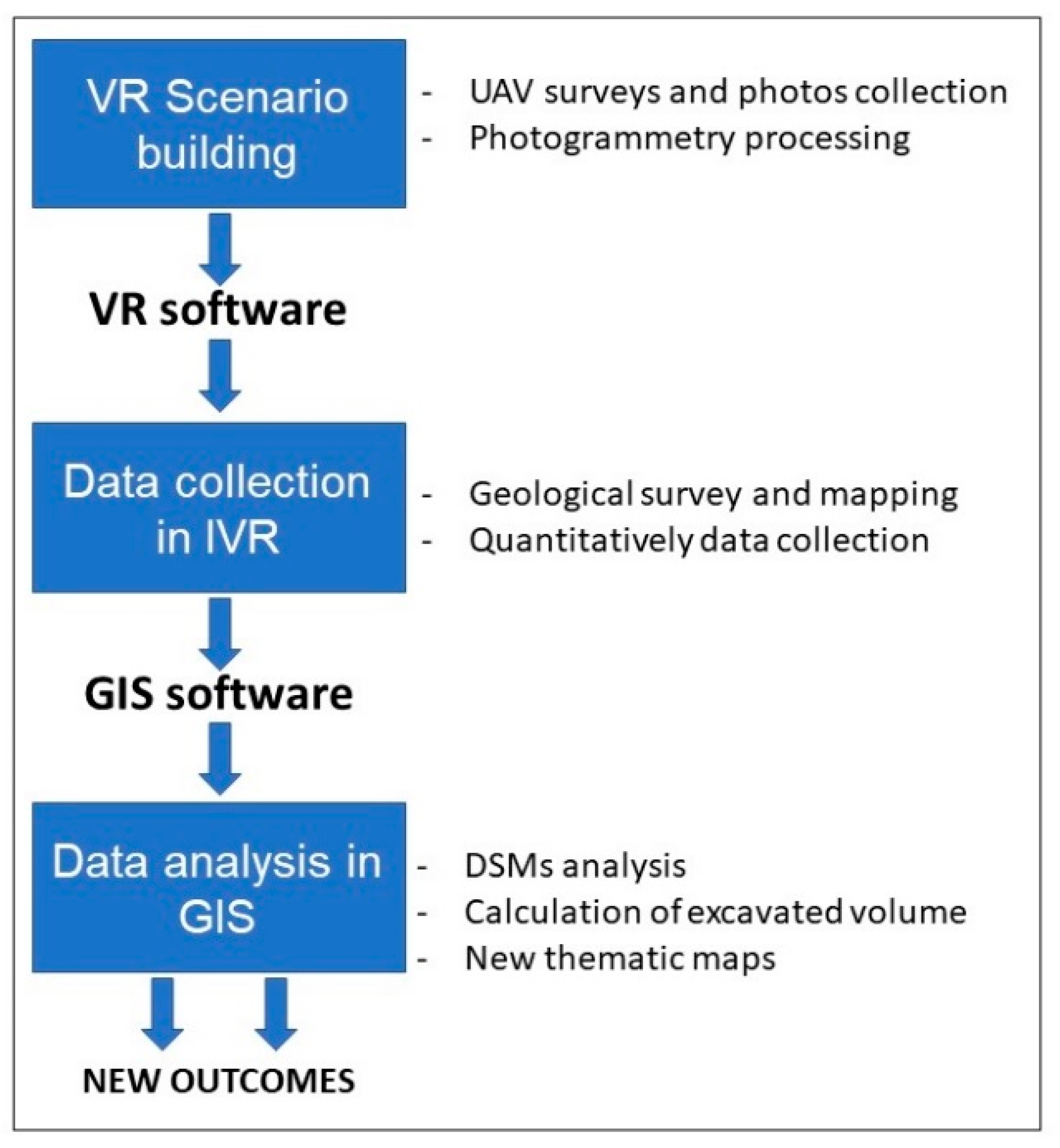
Figure 1. Overall conceptual workflow used in the present work; each box is related to a relevant part of the manuscript (VR: Virtual Reality, UAN: Unmanned Aerial Vehicle, IVR: Immersive Virtual Reality, GIS: Geographic Information System, DSM: Digital Surface Model).
Applsci 10 08317 g001
Figure 2. (a) Location of the Metaxa Mine within the Santorini Volcanic complex (modified from [17,18]). (b) Satellite view of the Metaxa Mine area, where the part that has been surveyed in the present work is highlighted by the black box (modified from [19]). (c) Panoramic field-view of the famous Late Bronze Age (LBA)-section, in the western part of the area (modified from [19]).
Applsci 10 08317 g002
Figure 3. Present-day Metaxa mine, looking to the southeast (a) and to southwest (b) (Credits: F.L. Bonali); (c) photo showing the entrances of the galleries of the “cut” and the boundary between volcanic phases P1 and P2 (modified from [51]) and (d) Metaxa pumice mine with a pier for loading bulk carriers (Credits: P. Nomikou).
Applsci 10 08317 g003
Figure 4. (a) The first version of§ Virtual Reality (VR): the Sensorama, images are free of use from Heilig (1962), US Patent #3,050,870. (b) Example of a geologist surveying the territory using GeaVR (Credits: F.L. Bonali). (c) Navigation modes selection during survey in Immersive Virtual Reality (IVR) using GeaVR software, from the left to right: walk, drone and airplane mode. (d) All tools available in GeaVR, regarding mapping, field survey and Global Position System (GPS) tools.
Applsci 10 08317 g004
Figure 5. Example of pictures captured during the drone survey with the camera oriented in Nadir (a) and Oblique (b). (c) Summary of the overall surveyed area: each subarea is represented by white boxes, Nadir and Oblique captured images are represented by blue dots and yellow squares, respectively. Reference system: WGS84/UTM35.
Applsci 10 08317 g005
Figure 6. Sparse (a) and dense (b) points clouds derived by photogrammetry processing.
Applsci 10 08317 g006
Figure 7. Structure from Motion (SfM)-derived Digital Surface Model (DSM) (a) and Orthomosaic (b) of the study area, with corresponding resolution indicated in the lower center. Altitudes are shown as a color range (legend in figure), Ground Control Points (GCPs) are represented by blue dots; reference system: WGS84/UTM35. (c) The final three-dimensional (3D) Tiled model.
Applsci 10 08317 g007
Figure 8. (a,b) Original photos scanned at 1600 dpi; (c) orthorectified model that was created using six Ground Control Points (GCPs) (blue triangles) and 116 automatic generated tie points (green cycle); (d) ortho image with pixel size of 1 m; (e) final DSM created with pixel size 1 m and accuracy 2 m horizontally and 1 m vertically; (f,g) orthomosaic of 1960s stereo images and generated digital surface model of the area, where the excavated area is located. Reference system: WGS84/Geographic coordinates.
Applsci 10 08317 g008
Figure 9. Snapshot of survey in Immersive Virtual Reality (IVR) aimed at an overall recognition of the volcanic layers belonging to the Late Bronze Age (LBA) eruption that are exposed in the mine, using the drone navigation mode.
Applsci 10 08317 g009
Figure 10. Different aspects of the mine’s morphology captured in GeaVR session using orthomosaic created during UAV survey. In each one, the upper boundary of excavation (orange line), the boundary between phases P4 and P2 (blue line), as well as the body of debris flows (yellow line) was mapped. (a) Mapping of anthropogenic debris areas and location of screenshots c and d; (b) location of machineries found in the mine; (c,d) anthropogenic debris along with natural debris flows; (e) the famous section consisted of eruption phase boundaries; in addition, the debris flow body was mapped.
Applsci 10 08317 g010
Figure 11. Workflow followed in order to calculate the total volume of excavation materials. (a) The DSM generated by UAV photos and SfM techniques (left) was cleaned, removing anthropogenic debris and debris flows, and the removed values were replaced by interpolated ones (right), (b) the DSM generated by 1960s aerial photos (left) was clipped to excavation boundary (right), (c) 3D representation of the final surfaces generated from (a,b) on the left and on the right the common area between the two models that corresponds to excavation materials.
Applsci 10 08317 g011
Figure 12. Different view angles of the estimated interpolated surface between eruption phases P2 and P4, along with the elevation points digitized in GeaVR.
Applsci 10 08317 g012
Figure 13. Thematic map summarizing all features mapped using the IVR approach, as well as the location of collected quantitative measurements.
Applsci 10 08317 g013
Figure 14. View of the 3D model of the Metaxa Mine (a) and the famous LBA-section (b) available on https://geovires.unimib.it/.
Applsci 10 08317 g014
Table 1. UAV survey dates and detailed flight acquisition parameters for missions with nadir camera orientation.
Mission 1Mission 2 Mission 3Mission 4Mission 5Mission 6Mission 7Mission 8
UAV Images Acquisition (Nadir)Flying Date14/10/201814/10/201816/10/201816/10/201816/10/201816/10/201817/10/201817/10/2018
Flying Height (m)3030303030303030
Frontal Overlap (%)9090909090909090
Lateral Overlap (%)8585858585858585
Flight Speed (m/s)1.61.61.61.61.61.61.61.6
Shutter Interval (s)22222222
Ground Resolution (cm/pix)0.90.90.90.90.90.90.90.9
Flying Time (mins)1921192019171815
Covered Area (m2)16,65318,82417,06816,325989912,75112,6206837
Images Numbers 554567485584486522447251
Table 2. UAV survey dates and detailed flight acquisition parameters for missions with oblique camera orientation.
Mission 1Mission 2 Mission 3Mission 4
UAV Images Acquisition (Oblique)Flying Date14/10/201814/10/201817/10/201817/10/2018
Flying Height (m)10 ÷ 4010 ÷ 4010 ÷ 4010 ÷ 40
Gimble orientation−45° ÷ −70°−45° ÷ −70°−45° ÷ −70°−45° ÷ −70°
Flight Speed (m/s)1–21–21–21–2
Shutter Interval (s)2222
Flying Time (mins)21211913
Images Numbers 504579471344
Table 3. Summary of resolution and time processing for DSM, Orthomosaic and 3D tiled models derived using photogrammetry.
SfM Photogrammetry processingAlignment processing accuracyHigh
Dense Cloud processing accuracyMedium
Dense Cloud Points132,527,363
3-D Tiled Model Resolution0.9 cm/pix
DSM Resolution cm/pix3.7 cm/pix
Orthomosaic Resolution cm/pix0.9 cm/pix
SfM Photogrammetry Processing Time (hours)
Images AcquisitionAligmenntDense Cloud3-D Tiled ModelDSMOrthomosaicOverall Processing
3.7 15.68 4.50 13.10 0.102.50 39.6
Table 4. Overall estimations for volume of extracted materials.
VolumeLiteratureThis Study
Total excavation of the Metaxa mine areaabout 4.5 million m3-
Total Excavation of study areaabout 1.3 million m31,660,141.89 m3
Excavation of Phase 4-794,386.02 m3
Publisher’s Note: MDPI stays neutral with regard to jurisdictional claims in published maps and institutional affiliations.