Article

Numerical Prediction of Equivalent Mechanical Properties of Corrugated Paperboard by 3D Finite Element Analysis

1
Department of Bio-Industrial Machinery Engineering, Pusan National University, Miryang 50463, Korea
2
Department of Logistic Packaging, Kyongbuk Science College, Chilgok 39913, Korea
*
Author to whom correspondence should be addressed.
Appl. Sci. 2020, 10(22), 7973; https://doi.org/10.3390/app10227973
Submission received: 8 October 2020 / Revised: 2 November 2020 / Accepted: 3 November 2020 / Published: 10 November 2020
(This article belongs to the Section Applied Industrial Technologies)

Abstract

:
This study is to obtain the equivalent (effective) mechanical properties of corrugated paperboard specifically that is widely applied in Korea for packaging of agricultural products. To analyze the equivalent properties of corrugated paperboard, finite element modeling, measurement of the reaction force, and superposition theory for the unit cell were applied. The stress-strain behavior obtained by applying the calculated equivalent mechanical properties to the simplified model of the corrugated paperboard is compared with experimental results. Nine equivalent mechanical properties governing the orthotropic behavior of corrugated paperboard were analyzed through finite element analysis (FEA). The stress-strain behavior of the corrugated paperboard experimentally showed elastic-plastic behavior, although the equivalent mechanical properties applied to the simplified model were elastic properties based on the theoretical approach, so that the finite element analysis results showed linearity. Therefore, when applying the calculated equivalent mechanical properties through FEA, the characteristics of the section where the strain only increases without the increase in the load due to the flute should be taken into consideration.

1. Introduction

Corrugated paperboard is a sandwiched engineering structure, whose strength characteristic is in accordance with cross-sectional geometry of flute and material properties of linerboard and corrugating medium [1,2,3,4,5]. Corrugated paperboard is an environmental friendly packaging material with high stiffness and strength [2,5,6,7,8]. In addition, it is efficient and easy to use to protect the contents of the package.
In Korea, linerboard and corrugating medium made by mixing imported old corrugated container (OCC) and Korea OCC at a certain ratio have been widely used for making corrugated paperboard. The corrugated paperboard with AB-flute double-wall (AB/F-DW) is widely used to maintain the strength of corrugated paperboard. Among corrugated paperboard produced in Korea in 2017, approximately 53.4% was the AB/F-DW corrugated paperboard, which was 1.15 times more than the used amount of SW (A/F and B/F) corrugated paperboard (KCCA, 2018). Recently, the application of corrugated paperboard in Korea has gradually expanded because a BB-flute double-wall (BB/F-DW) corrugated paperboard box having similar compressive strength to the AB/F-DW corrugated paperboard box has the advantage of reducing the package size. In addition, the use of corrugated paperboard has extended from the simple material of the box to materials of various cushion structures and pallets.
Even though the corrugated paperboard-based structure is efficient to protect package contents, there are still many empirical factors in the design of corrugated paperboard-based structures such as boxes, pallet and cushion. Finite element analysis (FEA) can be used to analyze strength and economic optimization of such structures depending on the factors. Since the analysis of behavior of both paper and corrugated paperboard using FEA was complex, FEA was uncommonly used in the corrugated paperboard industry. However, applications of FEA to corrugated paperboard have recently increased by taking advantage of advanced modeling for composite sandwich structures similar to corrugated paperboard [9].
By applying FEA to structure analysis of corrugated paperboard, it was possible to simulate geometric nonlinearity (large deformation), material nonlinearity (plasticity), and stiffness properties of different structures of corrugated paperboard, which was agreed well with experimental results [8,10,11]. Several researchers have applied FEA to the parametric study of the post-buckling strength of corrugated paperboard sandwich panels. Nordstrand [4] used FEA to evaluate the buckling load and collapse load of the sandwich panel. Fadiji et al. [11] performed linear buckling analysis using FEA on the edgewise compression test (ECT) model to determine the most buckling shape and estimate the critical buckling load. Peterson [12] used the FE (finite element) model to analyze the stress fields occurring in the machine direction (MD) of the combined board beam. The FE model has also been applied to the analysis of the bending stiffness and the ECT strength of corrugated paperboard structures, and to the analysis of the board combinations of corrugated paperboard that have advantageous properties [5,13,14,15,16].
The developed FEA has shown great analysis results of corrugated paperboard-based complex structure; however, a significant time and effort are required for modeling and analysis. By considering both the shape of the corrugated paperboard and the nonlinearity of its constituent boards, the nonlinearity of the corrugated paperboard can be well expressed through FEA. However in this case, it is impossible to realistically analyze the nonlinearity of the corrugated paperboard due to the enormous analysis time and the lack of convergence of the calculation process.
To overcome the inherent problem, the structural analysis of the repeating unit cell in corrugated paperboard should be first performed and it is necessary to derive the equivalent (effective) mechanical properties of the entire structure. Then, the determined equivalent mechanical properties should be applied to the simplified model. The number of studies regarding the equivalent mechanical properties of corrugated paperboard has been steadily increasing [2,4,6,17]. However, these studies are limited to the analysis of SW corrugated paperboard, and no attempt to determine the equivalent mechanical properties of AB/F and BB/F corrugated paperboard used in Korea.
Therefore, this study was conducted (1) to perform FE modeling for a unit cell of the corrugated paperboard by the flute type (AB/F, BB/F, A/F) and (2) to analyze the equivalent (effective) mechanical properties of corrugated paperboard by the reaction force measurement through FEA for unit cells.

2. Materials and Methods

2.1. Sample Preparation

Corrugated paperboard is an orthotropic sandwich structure consisting of liners and flute that provide bending stiffness and shear stiffness, respectively (Figure 1). Depending on the number of flutes, corrugated paperboard is classified into single-wall (SW), a double-wall (DW), and a triple-wall (TW) corrugated paperboard [18]. Flute is also categorized into A/F, B/F, C/F depending on flute height and take-up factor [19].
Corrugated paperboard is an orthotropic material that has three symmetry planes for the elastic properties. It has different mechanical properties in each direction (machine direction (MD, x), the cross direction (CD, y), the thickness direction (TD, z) due to the shape of the flute. Alternatively, corrugated paperboard components such as linerboard and corrugated medium exhibit orthotropy due to the fiber orientation. The paper fibers are oriented in MD while forming the paper sheets of machine-made paper board.
The types of corrugated paperboard used in this study were DW-AB/F, DW-BB/F and SW-A/F. The board combinations and main specifications for the corrugated paperboard are summarized in Table 1.

2.2. Measurement of Material Properties of Linerboard and Corrugated Medium

The machine direction (MD) and cross direction (CD) tensile tests for linerboard and corrugated medium used for fabrication of the corrugated paperboard samples were conducted according to ISO 1924-2 [20] and 187 [21]. A universal testing machine (UTM) was used for the tensile test. To reduce the error due to pre-failure of the contact between the test sample and the grip during the tensile test, the shape of the tensile test samples was modified in accordance with ISO 6892-1 [22] (Figure 2).
Since the corrugated paperboard components (linerboard, corrugating medium) are also orthotropic, nine unknown parameters (Ex, Ey, Ez, νxy, νxz, νyz, Gxy, Gxz, and Gyz) should be determined. However, some unknown parameters are not straightforward to measure because of the thin thickness of paper. The in-plane properties (Ex and Ey,) can be easily obtained by standard tests, e.g., stress-strain curves (S-S curve). The approximate estimation method is commonly used to determine the rest of the unknown parameters. The elastic modulus in the out-of-plane direction and the shear modulus of each direction can be approximated by Equations (1) and (2) [23,24,25], respectively.
E z = E x / 200
G x y = 0.387   E x E y ,   G x z = E x 55 ,   G y z = E y 35

2.3. Theoretical Consideration for Modeling

The constitute equation of the stress-strain relationship, which represents the mechanical properties of orthotropic material, is given by:
[ ε 1 ϵ 2 ϵ 3 γ 23 γ 31 γ 12 ] = [   1 E 1   ν 21 E 2   ν 31 E 3   0   0   0 ν 12 E 1   1 E 2   ν 32 E 3   0   0   0 ν 13 E 1   ν 23 E 2   1 E 3   0   0   0   0   0   0   1 G 23   0   0   0   0   0   0   1 G 31   0     0   0   0   0   0   1 G 12 ] [ σ 1 σ 2 σ 3 τ 23 τ 31 τ 12 ]
where ε 1 is the tensile strain in the x direction. ε 2 and ε 3 are the Poisson shrinkage strain in the y and z directions, respectively. E 1 is elastic modulus (Pa), G s are shear modulus (Pa), γ 12 are shear strain at a different direction (unit), ν i j is Poisson’s ratio at ith number.
Since ν i j / E i = ν j i / E j and υ i j = ϵ j / ε i , ν i j ν j i . Therefore, the number of engineering constants of constitute equation for describing the behavior of orthotropic material is 9. For the evaluation of the equivalent mechanical properties, 9 constants should be calculated from Equation (1).
To evaluate the equivalent mechanical properties of a structure, it is important to determine the unit cell representing the average response of the structure. The unit cell be selected as a repeating minimum basic unit in terms of the geometry and boundary conditions. Equivalent mechanical properties are evaluated through numerical experiments on the selected unit cell. In other words, the i-directional equivalent elastic modulus Ei and the equivalent shear modulus Gij can be obtained by simulating the uniaxial tensile and in-plane shear load states that resemble the actual test, respectively.
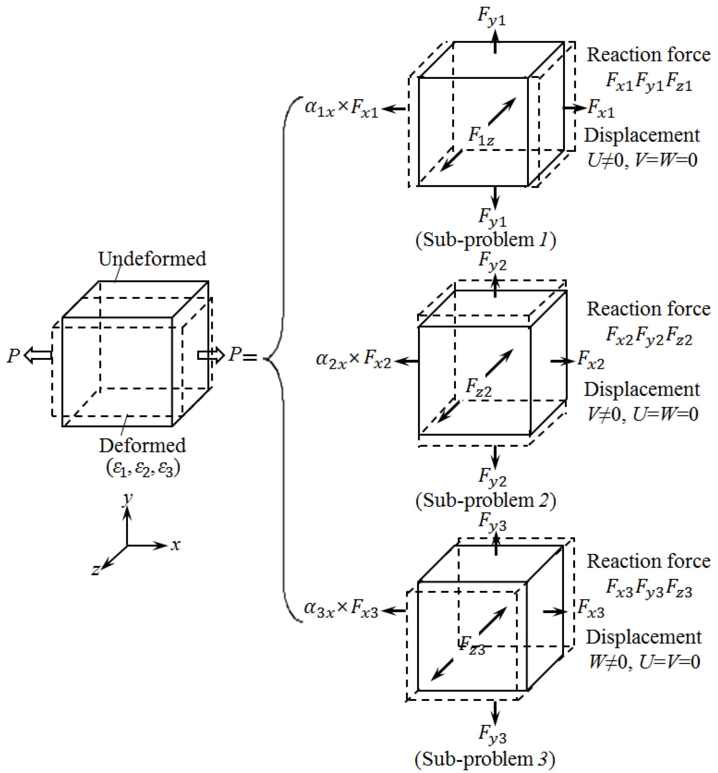
To obtain the equivalent elastic modulus E1, it is assumed that a uniaxial tensile load is applied as shown in Figure 3. The uniaxial tensile load state is simulated by dividing into three sub-problems and then superimposing the results linearly. The solid line and dotted lines indicate the shape before and after deformation, respectively. Here, the tensile strain ε 1 in the x-direction and Poisson shrinkage strain ε 2 and ε 3 in the y- and z- direction be obtained using the superposition method.
In Sub-problem (1), the strain on the other directions is constrained to zero except for the tensile strain in the x-direction. For the Sub-problems (2) and (3), displacement boundary conditions are applied so that the deformation of the other side was 0, except for the tensile deformation in the y- and z-directions. The reaction force at the interface can be obtained when FEA is performed on the sub-problems. To simulate the uniaxial tensile state, the obtained reaction forces are multiplied by weight coefficient α for Sub-problems (1), (2), and (3), respectively, and are combined as the following equation:
[ F ] i j [ α ] j i = [ P ] i j
where F is reaction force (N), α is weight (kg), P is applied load (kg) i indicates x, y, and z direction, j indicates sub-problems numbers.
By using the determinant, the coefficient matrix [α]ji can be obtained, and the strain under an applied load [F]ij can be obtained using the matrix, as indicated in Equation (5).
[ ϵ ] i j = [ α 1 x ϵ x   α 2 x ϵ x   α 3 x ϵ x α 1 y ϵ y   α 2 y ϵ y   α 3 y ϵ y α 1 z ϵ z   α 2 z ϵ z   α 3 z ϵ z ]
The work Wx by the tensile load Px, and the internal energy Ux stored in the unit structure are estimated from the following equations:
W x = 1 2 P x u = 1 2 P x ( Δ x ϵ 1 x )
U x = 1 2 v σ 1 ϵ 1 x d V = 1 2 E 1 ( ϵ 1 x ) 2 V
Since the work Wx by the tensile load Px, is equal to the internal energy Ux stored in the unit structure, the equivalent elastic modulus E1 for Sub-problem (1) can be calculated from Equation (8). E2 and E3 for Sub-problem (2) and (3) are also obtained from Equations (9) and (10).
E 1 = P x ( Δ y Δ z ) ϵ 1 x = P x ( Δ y Δ z ) α 1 x ϵ x
E 2 = P y ( Δ z Δ x ) ϵ 2 y = P y ( Δ z Δ x ) α 2 y ϵ y
E 3 = P z ( Δ x Δ y ) ϵ 3 z = P z ( Δ x Δ y ) α 3 z ϵ z
where Δx, Δy, and Δz represent the dimensions of the unit cell.
Equivalent Poisson’s ratio is given by:
ν 12 = ϵ 1 y ϵ 1 x = α 1 y ϵ y α 1 x ϵ x ,   ν 23 = ϵ 2 z ϵ 2 y = α 2 z ϵ z α 2 y ϵ y ,   ν 31 = ϵ 3 x ϵ 3 z = α 3 x ϵ x α 3 z ϵ z
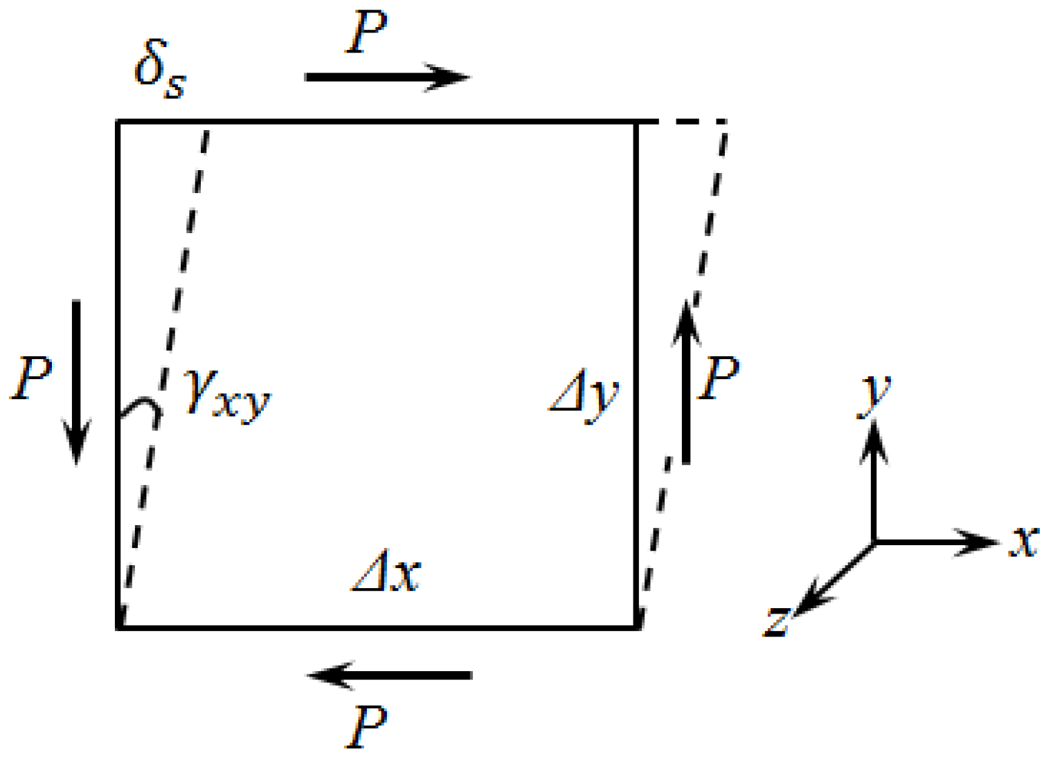
The calculation of the equivalent shear coefficients for orthotropic materials should be conducted separately because the shear stress only produces shear deformation of the component. After performing FEA under the boundary condition in which the unit cell is in the state of pure shear deformation, the equivalent shear modulus can be calculated from Equation (12) derived from the relation between the work W by the shear load and the energy U stored in the unit cell (Figure 4).
W = 1 2 P δ s = 1 2 P γ Δ y   ( tan γ γ = δ s Δ y )
U = 1 2 G 12 γ 2 V = 1 2 G 12 γ 2 ( Δ x Δ y Δ z )
G 12 = P γ 12 ( Δ x Δ z )
With the same calculation method for G12, the equivalent shear modulus G23 and G31 can be derived from Equations (15) and (16), respectively.
G 23 = P γ 12 ( Δ x Δ z )
G 31 = P γ 12 ( Δ x Δ z )

2.4. Model Development

Through the preliminary analysis of various repetition models, modeling for the unit cell in the MD of the corrugated paperboards used in this study was three times the minimum repetition level based on the integer multiples of the A/F and B/F wavelength. This accounted for the dimension that can overcome the excessive reaction force at the constraint points of both ends in the x-direction. The dimensions were 18 mm for AB/F-DW and BB/F-DW corrugated paperboard, and 27 mm for A/F-SW corrugated paperboard. However, the dimension of the unit cells in the CD was taken as unit lengths on all corrugated paperboard samples and modeled as solid state considering the thickness direction.
MiDAS NFX (2018R2, MiDAS IT) software was used for FE modeling [26]. The interface between the flute and liner of the corrugated paperboard was joined to simplify modeling. The geometrical shape of the flute was modeled as a sine function based on the data shown in Table 1. The FE modeling for the unit cells of the corrugated paperboard samples is indicated in Figure 5. The hexahedral mesh was used due to the shape of corrugated papers. The computational domains for AB/F-DW, BB/F-DW, and A/F-SW were discretized into 156,825 nodes and 102,400 mesh elements, 148,767 nodes and 97,200 mesh elements, and 144,228 nodes and 94,200 mesh elements, respectively.
The boundary conditions applied when analyzing the three vertical displacements and shear displacements were applied according to the methods shown in Figure 3 and Figure 4. As a representative example, the AB/F-DW case is shown in Figure 6 and Figure 7.

2.5. Model Suitability

The suitability of the analysis model was confirmed by calculating the Mesh Convergence Error using Equation (1) [27]:
e σ i 1 σ a v e v t 1 / 3 { ( σ i σ e x ) v i 1 / 3 } 2 N
σ a v e = v i σ i 2 v i
here, σ a v e is the RMS (root mean square) value of the stress obtained over the entire area of the model with respect to the volume, and ν i and ν t represent the volume of the element and the analysis model, respectively.
σ e x w i σ i
where σ i , w i and N denote the stress, weight (1/N) and the number of adjacent elements, respectively.
Representative examples of mesh convergence errors in vertical and shear deformation analysis are shown in Figure 8 and Figure 9, respectively, and the values for each analysis are summarized in Table 2.

3. Results and Discussion

3.1. Physical Properties of Corrugated Paperboard Components

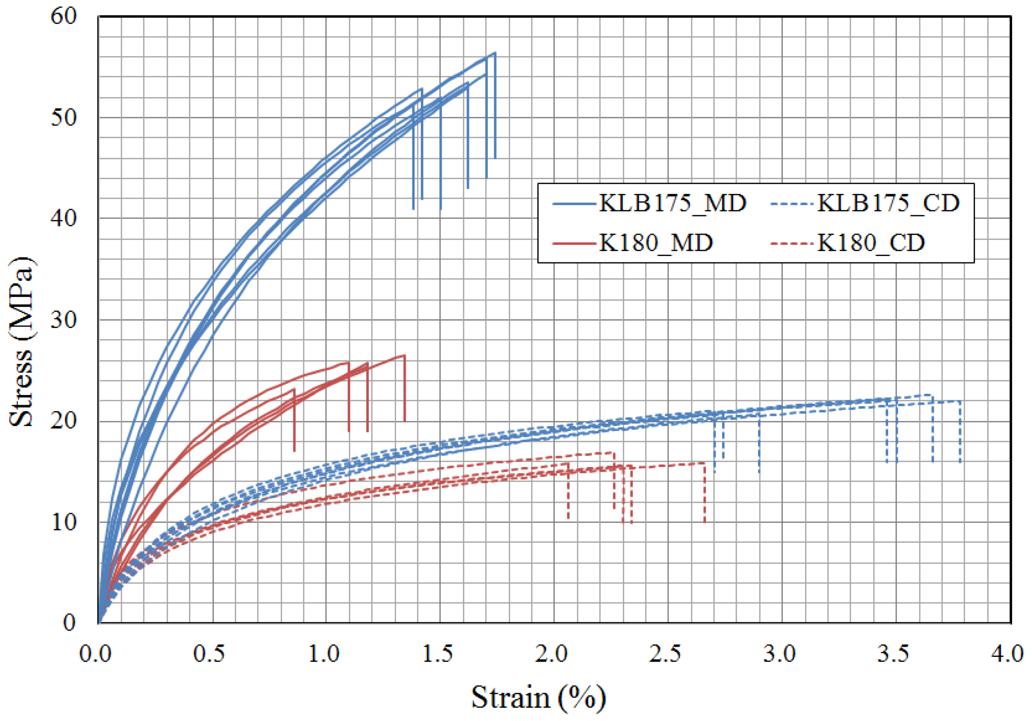
Figure 10 shows the stress-strain(S-S) curves of the uniaxial tensile test on the linerboard and corrugating medium of corrugated paperboard samples. The high anisotropic and non-linear mechanical behavior was observed. In ISO 1924-2 [20], the elastic modulus of the paper is defined as the maximum slope on the S-S curve. However, when ISO 1924-2 method was applied to the test results of the corrugated paperboard components used in this study, very high elastic modulus was calculated. If the elastic modulus is applied to FEA, the result from FEA indicates a significant difference from the actual behavior of the corrugated paperboard. Thus, in this study, the elastic modulus in the MD and CD of the corrugated paperboard components was represented by the secant modulus, which was the slope of the line connecting the origin point and the rupture point.
The other physical properties (Ez, Gxy, Gxz, Gyz) were calculated from Equations (1) and (2). The νxy, νxz, and νyz values were approximated and determined according to the material values similar to corrugated paperboard samples (0.33 for the corrugating medium and 0.34 for the linerboard) used in previous studies [4,10]. The physical properties of corrugated paperboard samples are summarized in Table 3 were applied to FEA.

3.2. Calculation of Equivalent Material Properties of Corrugated Paperboards

In order to obtain the equivalent mechanical properties of the corrugated paperboard depending on flute type, the physical properties (Table 3) of linerboard and corrugating medium were applied to the FE model for the unit cells (Figure 5) of corrugated paperboard samples. Since the contact surface conditions of FEA were the contact areas between the linerboard and the flute of corrugated paperboard, the number of contact surfaces in DW and SW corrugated paperboards was set to 4 and 2, respectively. As aforementioned, the interface between the flute and liner of the corrugated paperboard was considered to be joined for the convenience of FEA.
First, to obtain the equivalent elastic modulus, the reaction force was measured through FEA with each constraint given to the three sub-problems (Figure 3). The reaction forces (Fxi, Fyi, and Fzi) were measured in the state in which forced displacement of 1 mm was applied in the x, y, and z-directions, respectively. In this case, all degrees of freedom were constrained in all directions except for the direction in which the forced displacement was applied: the y and z-directions when measuring Fxi, the x, and z-directions when measuring Fyi, and the x and y-directions when measuring Fzi.
The measured directional reaction force for unit cells of corrugated paperboard samples through FEA are shown in Figure 11, Figure 12 and Figure 13. In addition, the measurement results of the reaction force for the three sub-problems are provided in Table 4. The measured reaction forces through FEA were not significantly different from the measured reaction forces in tension and compression test. The corrugated paper board is mainly subjected to compressive force when it is applied to the product packaging and cushioning. Therefore, the reaction force measured under compressive load was applied to the analysis of the equivalent elastic modulus for the corrugated paperboard samples.
The equivalent elastic modulus for the corrugated paperboard samples could be calculated by applying the reaction forces listed in Table 4 to Equations (2) and (5)–(7). The calculated results are summarized in Table 5. For example, the equivalent elastic modulus for AB/F-DW corrugated paperboard was calculated as follows. The coefficient ([α]ji, relative ratio) was calculated by substituting the reaction forces obtained from FEA for each sub-problem into Equation (2). The coefficient for each sub-problem was calculated by applying the cross-sectional area and the strain of AB/F-DW corrugated paperboard (Table 5) and arbitrary load ([P]ji = 100 N). The calculated coefficients are listed in Table 6.
The procedure for obtaining the equivalent shear modulus was similar to that for the equivalent elastic modulus. The constraint was given to three sub-problems, and the reaction force in each direction was measured through FEA. The reaction forces Fxyi, Fyzi, and Fzxi were measured in the state in which forced displacement of 1 mm was applied in the x-direction of the upper face xz (fixing lower face xz with xy plane in front), the y-direction of the upper face xy (fix lower face xy with yz plane in front), and the x-direction of the upper face xy (fix lower face xy with xz plane in front), respectively. In these cases, all degrees of freedom were constrained in all directions except for the direction in which the forced displacement was applied: the y and z-directions when measuring Fxyi, the x and z-directions when measuring Fyzi, and the z and y-directions when measuring Fzxi.
Figure 14, Figure 15 and Figure 16 show the directional reaction force measurement for the unit cell of corrugated paperboard samples, and the measurement results are provided in Table 7. The equivalent shear modulus was calculated by applying the reaction force listed in Table 7 to Equations (11)–(13). For example, the equivalent shear modulus for AB/F-DW corrugated paperboard was calculated as follows. The calculation of the equivalent shear modulus was much simpler than the calculation of the longitudinal modulus. Instead of combining nine reaction components by applying a load in each direction to each sub-problem, the equivalent shear modulus be easily obtained from the reaction force measured by applying a shearing force to each model. The cross-sectional area and shear deformation angle of AB/F-DW (Table 8) were substituted in Equations (11)–(13) to obtain the equivalent shear modulus.
Equivalent Poisson’s ratio for the target corrugated paperboards was calculated using Equation (8). The calculated elastic modulus, shear modulus, and Poisson’s ratio in all directions are summarized in Table 9.

3.3. Stress-Strain Behavior Using Equivalent Materials Properties of Corrugated Paperboard

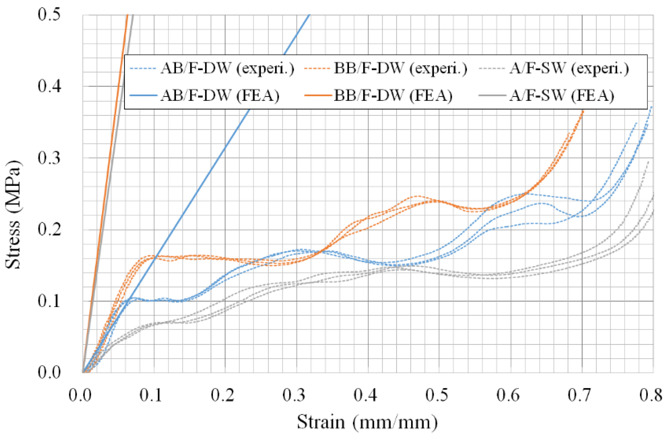
In order to perform FEA on the flat crush resistance, the calculated equivalent mechanical properties of the corrugated paperboard samples were applied to the simplified FE models (Figure 17). The simplified model was discretized into 156,825 nodes and 102,400 mesh elements. The S-S behavior (flat crush resistance) of the simplified FE model was compared with experimental data of corrugated paperboard samples obtained by following ISO 3035 [27] (Figure 18). In case of the flat crush test of corrugated paperboard samples, the S-S curve was measured when a circular metal plate that has 90.6 mm in diameter and was attached the upper cross-head of tester exerted compressive force on corrugated paperboard sample (length × width = 30 × 30 cm). The loading rate was 12.5 ± 2.5 mm/min. Sandpaper was attached to the upper and lower compression plates of the tester in contact with the test piece to reduce the experimental error by the swelling of the flute in the test piece of the corrugated paperboard. However, the FEA for the simplified model of corrugated paperboard samples was reproduced by simulating the same conditions as the experiment.
When the upper surface of the model with a diameter of 90.6 mm was forcibly displaced at the same loading rate as the experiment in the z-direction, the reaction force transmitted to the lower surface of the model and S-S curves were measured and recorded. In FEA, the lower surface of the model was restricted to the translational and rotational motion in the x, y, and z-directions; however, the upper surface was restricted only to translational motion in x and y-directions.
The flat crush behavior of the corrugated paperboard samples showed elastic-plastic behavior when it exceeded a certain strain; however, the calculated equivalent value was the result of the theoretical approach assuming the elastic region.
As expected, the difference between the simulated and experimental values was observed in the region beyond the elastic region. In the actual behavior of the corrugated paperboard, the liner of the corrugated paperboard was deformed in the shear direction because of the change of the flute shape. Therefore, the experiment showed more significant deformation at smaller loads than ideal conditions such as FEA (Figure 18). As a result, when the equivalent mechanical properties calculated by FEA were used to simulate S-S behavior of corrugated paperboard, it was necessary consider the characteristics of the region where the strain increased without an increase in load due to the flute of the corrugated paperboard.

4. Conclusions

Simulation techniques such as FEA must avoid the experimental factors in the design of various structures made of corrugated paperboard and to achieve the optimum design. However, due to the complexity of the corrugated paperboard itself in FEA for these structures, a significant time and effort are required for modeling and analysis. Therefore, it is necessary to analyze the simplified model and the equivalent mechanical properties for corrugated paperboard by flute type.
In this study, the equivalent mechanical properties for corrugated paperboard were analyzed by measuring the reaction force generated by applying a forced displacement to FE model for a unit cell of a corrugated paperboard with the same shape repeatedly. In addition, the analyzed equivalent mechanical properties were applied to a simplified model of the corrugated paperboard to analyze the S-S behavior through FEA. The results were compared with experiments.
The S-S behaviors of the corrugated paperboard analyzed by the FEA and experimental methods showed a significant difference above a certain amount of strain. The S-S behavior of the corrugated paperboard experimentally showed elastic-plastic behavior, although the equivalent mechanical properties applied to the simplified model of the corrugated paperboard were elastic based on the theoretical approach, so that the FEA results showed linearity. Therefore, when applying the calculated equivalent mechanical properties of the corrugated paperboard through FEA, consideration should be made about the characteristics of the section where the strain only increases without the increase of the load due to the flute of the corrugated paperboard. If the improved equivalent mechanical properties are applied to the FEA, it can be concluded that the FEA results close to the compressive behavior of corrugated paperboard can be obtained.
Although the nonlinearity was neglected in this study, the linearized and homogenized three-dimensional orthotropic equivalent mechanical properties be obtained, so that FEA in consideration of the effect of a certain section and the characteristics of the corrugated paperboard be easily performed.

Author Contributions

Data curation, J.P.; Formal analysis, J.P. and H.M.J.; Funding acquisition, J.P.; Investigation, J.P.; Resource, J.P. and H.M.J.; Software, J.P., S.C. and H.M.J.; Validation, J.P. and H.M.J.; Visualization, J.P. and S.C.; Writing-original draft preparation, J.P. and H.M.J.; Writing-review and editing, J.P. and H.M.J.; Supervision, H.M.J. All authors have read and agreed to the published version of the manuscript.

Funding

This work was supported by a National Research Foundation of Korea (NRF) grant funded by the Korea government (MSIT) (No. 2017R1A2B4010753).

Conflicts of Interest

The authors declare no conflict of interest.

References

  1. Biancolini, M.E.; Brutti, C.; Porziani, S. Corrugated board containers design methods. Int. J. Comput. Mater. Sci. Surf. Eng. 2010, 3, 143. [Google Scholar] [CrossRef]
  2. Biancolini, M.E. Evaluation of equivalent stiffness properties of corrugated board. Compos. Struct. 2005, 69, 322–328. [Google Scholar] [CrossRef]
  3. Haj-Ali, R.; Choi, J.; Wei, B.S.; Popil, R.; Schaepe, M. Refined nonlinear finite element models for corrugated fibreboards. Compos. Struct. 2009, 87, 321–333. [Google Scholar] [CrossRef]
  4. Nordstrand, T.M. Parametric study of the post-buckling strength of structural core sandwich panels. Compos. Struct. 1995, 30, 441–451. [Google Scholar] [CrossRef]
  5. Park, J.M.; Kim, G.S.; Kwon, S.H.; Chung, S.W.; Kwon, S.G.; Choi, W.S.; Mitsuoka, M.; Inoue, E.; Okayasu, T.; Choe, J.S. Finite element analysis of corrugated board under bending stress. J. Fac. Agric. Kyushu Univ. 2012, 57, 181–188. [Google Scholar]
  6. Aboura, Z.; Talbi, N.; Allaoui, S.; Benzeggagh, M.L. Elastic behavior of corrugated cardboard: Experiments and modeling. Compos. Struct. 2004, 63, 53–62. [Google Scholar] [CrossRef] [Green Version]
  7. Fadiji, T.; Berry, T.; Coetzee, C.; Opara, U.L. Investigating the mechanical properties of paperboard packaging material for handling fresh produce under different environmental conditions: Experimental analysis and finite element modeling. J. Appl. Packag. Res. 2017, 9, 20–34. [Google Scholar]
  8. Gilchrist, A.C.; Suhling, J.C.; Urbanik, T.J. Nonlinear finite element modelling of corrugated board. In ASME Applied Mechanics Division; Publications-AMD: New York, NY, USA, 1998; Volume 231, pp. 101–106. [Google Scholar]
  9. Jiménez, M.A.; Conde, I.; García, B.; Liarte, E. Design of different types of corrugated board packages using finite element tools. In Proceedings of the Simulia Customer Conference, London, UK, 18–21 July 2009; pp. 1–15. [Google Scholar]
  10. Biancolini, M.E.; Brutti, C. Numerical and experimental investigation of the strength of corrugated board packages. Packag. Technol. Sci. 2003, 16, 47–60. [Google Scholar] [CrossRef]
  11. Fadiji, T.; Coetzee, C.; Opara, U.L. Compression strength of ventilated corrugated paperboard packages: Numerical modeling, experimental validation and effects of vent geometric design. Biosyst. Eng. 2016, 151, 231–247. [Google Scholar] [CrossRef]
  12. Peterson, W.S. Flute/liner interaction for bending of combined board beams. Paperboard Packag. 1983, 68, 37–41. [Google Scholar]
  13. Jiménez, M.A.; Liarte, E. Simulation of the edge crush test of corrugated paperboard using ABAQUS. In Proceedings of the ABAQUS World Users Conference, Munich, Germany, 4–6 June 2003; pp. 1–12. [Google Scholar]
  14. Johnson, M.W.; Urbanik, T.J. Analysis of the localized buckling in composite plate structures with application to determining the strength of corrugated fiberboard. J. Compos. Technol. Res. 1989, 11, 121. [Google Scholar]
  15. Pommier, J.C.; Poustis, J. Bending stiffness of corrugated board prediction using the finite element method. Mech. Wood Pap. Mater. 1990, 112, 67–70. [Google Scholar]
  16. Park, J.; Park, M.; Choi, D.S.; Jung, H.M.; Hwang, S.W. Finite element-based simulation for edgewise compression behavior of corrugated paperboard for packaging of agricultural products. Appl. Sci. 2020, 10, 6716. [Google Scholar] [CrossRef]
  17. Kwon, K.Y.; Jung, J.Y. The mechanical properties of cardboard using equivalent evaluation. Soc. Korea Ind. Syst. Eng. 2014, 37, 157–164. [Google Scholar] [CrossRef]
  18. Korean Standard Association (KSA). Glossary of Terms Used in Corrugated Fibreboard Industry; KST T 1004; KSA: Seoul, Korea, 2010. [Google Scholar]
  19. Korean Standard Association (KSA). Corrugated Fibreboards for Shipping Containers; KST T 1034; KSA: Seoul, Korea, 2014. [Google Scholar]
  20. ISO. Paper and Board—Determination of Tensile Properties—Part. 2: Constant Rate of Elongation Method (20 mm/min); British Standard Institute (BSI): London, UK; International Electrotechnical Commission (IEC): London, UK, 1995; ISO 187:1990. [Google Scholar]
  21. ISO. Paper, Board and Pulps—Standard Atmosphere for Conditioning and Testing and Procedure for Monitoring the Atmosphere and Conditioning of Samples; ISO 187:1990; British Standard Institute (BSI) and International Electrotechnical Commission (IEC): London, UK, 1990. [Google Scholar]
  22. ISO 6892-1:2019. Metallic Materials—Tensile Testing—Part. 1: Method of Test at Room Temperature. Available online: https://www.iso.org/obp/ui/#iso:std:iso:6892:-1:ed-3:v1:en (accessed on 20 September 2019).
  23. Persson, K. Material Model for Paper: Experimental and Theoretical Aspects. Diploma Thesis, Lund University, Lund, Sweden, 1991. [Google Scholar]
  24. Baum, G.A.; Brennan, D.C.; Habeger, C.C. Orthotropic elastic constants of paper. Tappi 1981, 64, 97–101. [Google Scholar]
  25. Mann, R.W.; Baum, G.A.; Habeger, C.C. Determination of all nine orthotropic elastic constants for machine-made paper. Tappi 1980, 63, 163–166. [Google Scholar]
  26. MiDAS IT. Analysis Manual (2018R2); MIDAS IT: Seoul, Korea, 2018. [Google Scholar]
  27. ISO. Corrugated fiberboard—Determination of Flat Crush Resistance; ISO 3035:2011; British Standard Institute (BSI) and International Electrotechnical Commission (IEC): London, UK, 2011. [Google Scholar]
Figure 1. Three principal material axes in corrugated paperboard and its components.
Applsci 10 07973 g001
Figure 2. Detailed dimensions of tensile test specimen used in the study.
Applsci 10 07973 g002
Figure 3. Schematic representation of the superposition method.
Applsci 10 07973 g003
Figure 4. Unit cell under pure shearing force.
Applsci 10 07973 g004
Figure 5. The FE (finite element) models for the unit cells of the target corrugated paperboard; they should be listed as: (a) AB/F-DW, (b) BB/F-DW, and (c) A/F-SW (Table 1).
Applsci 10 07973 g005
Figure 6. Boundary conditions applied when analyzing the reaction force for vertical displacement (Z) (example: AB/F-DW); they should be listed as: (a) U = 0, (b) V = 0, and (c) W = 0.
Applsci 10 07973 g006
Figure 7. Boundary conditions applied when analyzing reaction force for shear displacement (XY) (example: AB/F-DW), they should be list as: (a) U = V = W = 0; (b) W = 0; (c) V = 0.
Applsci 10 07973 g007
Figure 8. Mesh convergence error for vertical displacement analysis (example: AB/F-DW), they should be list as: (a) X-direction (1.71%); (b) Y-direction (0.53%); (c) Z-direction (3.05%).
Applsci 10 07973 g008
Figure 9. Mesh convergence error for shear displacement analysis (example: AB/F-DW), they should be list as: (a) XY-direction (1.90%); (b) YZ-direction (6.62%); (c) ZX-direction (2.02%).
Applsci 10 07973 g009
Figure 10. In-plane tensile S-S curves for the linerboards and the corrugating mediums of target corrugated paperboard.
Applsci 10 07973 g010
Figure 11. Directional reaction force for the unit cell of AB/F-DW corrugated paperboard, they should be list as: (a) x-direction; (b) y-direction; (c) z-direction.
Applsci 10 07973 g011
Figure 12. Directional reaction force for the unit cell of BB/F-DW corrugated paperboard, they should be list as: (a) x-direction; (b) y-direction; (c) z-direction.
Applsci 10 07973 g012
Figure 13. Directional reaction force for the unit cell of A/F-SW corrugated paperboard, they should be list as: (a) x-direction; (b) y-direction; (c) z-direction.
Applsci 10 07973 g013
Figure 14. Directional reaction force for the unit cell of AB/F-DW corrugated paperboard, they should be list as: (a) xy-direction; (b) yz-direction; (c) zx-direction.
Applsci 10 07973 g014
Figure 15. Directional reaction force for the unit cell of BB/F-DW corrugated paperboard, they should be list as: (a) xy-direction; (b) yz-direction; (c) zx-direction.
Applsci 10 07973 g015
Figure 16. Directional reaction force for the unit cell of A/F-SW corrugated paperboard, they should be list as: (a) xy-direction; (b) yz-direction; (c) zx-direction.
Applsci 10 07973 g016
Figure 17. Simplified model of A/F-SW corrugated paperboard.
Applsci 10 07973 g017
Figure 18. Comparison the stress-strain behavior (flat crush resistance) between the simplified FE model and experiment for target corrugated paperboards.
Applsci 10 07973 g018
Table 1. Specifications of the target corrugated paperboards.
KindsBoard CombinationTotal Thickness (mm)Dimensions of FluteThickness of Paperboards (mm)
DW_AB/FKLB175/K180(B/F)/K180/K180(A/F)/KLB1758.0-wavelength (mm): A/F = 9.00, B/F = 6.00 -height of flute (mm): A/F = 4.60, B/F = 2.65 -take-up factor: A/F = 1.560, B/F = 1.424-KLB175 = 0.22 -K180 = 0.24
DW_BB/FKLB175/K180(B/F)/K180/K180(B/F)/KLB1756.0
SW_A/FKLB175/K180(A/F)/KLB1755.1
Note: KLB175 [18% UKP (Unbleached Kraft Pulp) + 20% AOCC (American Old Corrugated Container) + 62% KOCC (Korean Old Corrugated Container)], K180 (100% KOCC) Applsci 10 07973 i001
Table 2. Mesh Convergence Error (%).
CaseAB/F-DWBB/F-DWA/F-SW
Vertical displacement, X1.712.392.03
Vertical displacement, Y0.530.751.09
Vertical displacement, Z3.053.544.15
Shear displacement, XY1.903.061.94
Shear displacement, YZ6.626.536.75
Shear displacement, ZX2.022.873.61
Table 3. Material properties of corrugated paperboard components applied to FEA.
PaperboardElastic Modulus (GPa)Shear Modulus (GPa)Poisson’s RatioTensile Strength (kN/m)
Ex (MD)Ey (CD)EzGxyGxzGyzνxyνxzνyzσx (MD)σy (CD)
KLB1753.3810.6700.0170.5820.0610.0190.340.010.0111.744.74
(±0.209)(±0.082)(±0.40)(±0.24)
K1802.2800.6980.0110.4880.0410.0200.340.010.015.563.78
(±0.222)(±0.071)(±0.34)(±0.13)
Note: Values in parentheses are standard deviation values.
Table 4. Reaction forces (N) for 3 sub-problems.
ClassificationsAB/F-DWBB/F-DWA/F-SW
x-axisFx1−583.58−593.22−284.74
Fy1−163.41−169.07−105.49
Fz1−5.46−29.17−11.32
y-axisFx2−163.26−167.66−105.55
Fy2−3374.73−3306.89−2931.99
Fz2−3.43−14.59−12.45
z-axisFx3−7.88−47.09−41.81
Fy3−5.40−29.04−44.49
Fz3−17.97−120.86−177.82
Table 5. Strain under simple tension in AB/F-DW corrugated paperboard.
Directionsε1ε2ε3Area (mm2)
x0.056--39.65
y-0.200-142.74
z--0.12690.00
Table 6. Coefficients for the superposition method in AB/F-DW corrugated paperboard.
Directionsα1α2α3
x−0.174390.008360.07394
y0.00836−0.030040.00536
z0.051380.00319−5.58958
Table 7. Reactional forces (N) for 3 sub-problems.
ClassificationsAB/F-DWBB/F-DWA/F-SW
Fxy1634.861726.431580.28
Fyz83.64156.53138.97
Fzx8.7011.112.47
Table 8. Shear strain under simple shear in AB/F-DW corrugated paperboard.
DirectionsFγArea (mm2)
xy1634.860.197142.74
yz83.640.12590
zx8.700.05539.65
Table 9. Equivalent material properties for the corrugated paperboard samples.
Material PropertiesAB/F-DWBB/F-DWA/F-SW
Elastic modulus
(MPa)
Ex260.32345.50298.37
Ey116.60151.35106.24
Ez1.587.876.57
Shear modulus
(MPa)
Gxy58.0281.2558.83
Gyz7.4110.505.26
Gzx3.956.702.65
Poisson’s ratio
(-)
νxy0.1730.1770.189
νyz0.0670.0450.046
νzx0.0060.0260.027
Publisher’s Note: MDPI stays neutral with regard to jurisdictional claims in published maps and institutional affiliations.