Abstract
In the present study, a novel approach to estimating the efficiency of roller chain power transmission systems is proposed based on sliding friction losses and damping force. The dynamics model is taken into account between chain links with lateral offset owing to the derailleur system. Frictional losses were calculated according to Coulomb’s law of friction, and the damping force was dependent on the damping coefficient. The effects of rotational speed, load, derailleur system, and damping coefficient on transmission efficiency were analyzed. The test stand of the roller chain power transmission system was set up to verify the estimated efficiency, and the results showed a good correlation, demonstrating the validity of the chain power transmission efficiency estimation.
1. Introduction
Chains are widely used in bicycles, motorcycles, personal mobility devices, and various industrial equipment since they provide reliable, efficient, and durable power transmission with relatively low economic cost. Figure 1 presents a schematic of a roller chain, the most common and popular type of chain, in which the inner link is connected by a pin on the outer link, and the pin is covered by a bush and roller that contacts with the mating sprocket. The transmission efficiency of the chain drive system, which is the ratio of the input power of the driving sprocket to the output power of the driven sprocket, depends on the configuration of the chain and the operation conditions such as torque and speed. In the process of power transmission, energy loss occurs due to sliding friction between the pin, the roller, and the bush during the rotation of articulation, vibration in the chain spans, impact when the roller engages and disengages with the sprocket, and contacting force between the inner and the outer side plates of the derailleur system for gear shifting.
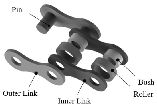
Figure 1.
Schematic of roller chain and its components.
Even though the roller chain drive system has been utilized for many years, little is known concerning how to estimate efficiency, which is affected by various factors, such as transmission speed, load, lateral offset between driving and driven sprockets, deflection of the tight side of the chain, etc. In 1999, Kidd et al. [1], performed an experimental examination in which tension was statically loaded for a bicycle chain with a sprocket under conditions of in-plane loading and out-plane loading. However, since only steady-state analysis for tension was carried out, the mechanical interaction of the roller chain and its components was not addressed. James C. Conwell and Johnson G.E. [2] in 1995 investigated the tension of link and impact force on roller sprockets in roller chains under various operation conditions and summarized the results by regression analysis. The impact force increased as the rotational speed and tension of link increased. However, the results did not provide thorough theoretical basis. In 2001, [3] James B. Spicer found that chain transmission is primarily affected by frictional energy loss between 97 and 99%, and compared and validated this result under various rotational speed, power, and lubrication conditions. However, regarding the aspect of chain drive to transmission efficiency with lateral offset, that study only theoretically modeled frictional loss, and experimental verification was not performed. Furthermore, [1,3,4] designed and analyzed the effects of lateral offset for a roller chain system, but inner contact of the chain link with lateral offset owing to the derailleur type system was not reported. Hollingworth, N.E. [5] and Hills, D.A. [6] in 1986 modeled and analyzed the link tension and theoretical efficiency of a chain and formulated the contact force of the pin and bush articulation. However, it is only used in a cranked chain, and does not apply to a roller chain. Although the roller chain system is lubricated, friction occurs at the contacts between the sprockets and the rollers. One advantage of presence of friction force is that it damps out high peak forces during the contact [7,8]. Additionally, Coulomb friction modeling is simple because it only requires the kinetic coefficient of friction. Burgess, S.C. [9] in 1998 calculated chain power transmission efficiency based on the energy loss between the chain links and sprockets and investigated the effects of size of sprockets. It was found that average chain transmission efficiency was 98.8%. However, this model is limited to a race cycling bike chain links that only include pin and sleeve without roller. In 2001, Lodge [10] and Burgess [11] assessed the efficiency of roller chains by modeling frictional losses due to pin sliding against the bush and bush sliding against the roller, in which sliding friction was based on Coulomb’s law of friction. The results of efficiency were in the range of 9–99% in high torque transmission. Troedsson, I. [12] and Vedmar, L. [13] in 2001 modeled a complete chain transmission with two sprockets and a chain with tight and slack spans. Damping force is considered as an important factor in the tight span that transmits the most power, and it is assumed to be proportional to the relative velocity between the two end points at the tight side. In 2004, Stuart Burgess and Chris Lodge [14] demonstrated that the efficiency of the chain is significantly influenced by the center distance between two sprocket axes, and showed that chain center distance is a key design parameter for motorcycles, although experimental verification was not achieved. Wragge-Morley, R. et al. [15], in 2018, estimated the drive transmission efficiency of the roller chain according to the sliding friction force among the pin, bush, and roller of a chain; however, the experimental test was only validated in the condition of low rotational speed. In 2018, Aleksey Egorov et al. developed a method that determined the transmission energy consumed to accelerate a rotating chain system [16,17,18,19]. In addition, chain efficiency was estimated by measuring the time of angular acceleration in the rotation axis of the drive shaft with and without load during the speeding-up of a chain drive. This method, however, could not discern the characteristics of a steady-state for a chain system, such as various affected parameters.
In computing the roller chain system efficiency, energy loss should be always considered. While some energy stored as elastic deformation of components is recovered, other energy losses due to friction and damping cannot be recovered. James B. Spicer et al. [3] estimated the bicycle chain drive efficiency based on the energy losses due to sliding friction. Theoretical efficiency of the chain system was found to be between 97 and 99%, however, the results from the experiment and theoretical analysis showed some discrepancy. In order to estimate the energy losses based on damping force, Troedsson, I. and Vedmar, L. [12] proposed a method to determine the load distribution during power transmission considering the damping factor. The damping force was modeled according to the damping coefficient and rotational speed of the chain span.
The aim of the present study is to estimate the efficiency of the roller chain transmission system considering energy losses due to sliding friction and damping force in the tight span. The sliding frictional force between the pin, the bush, and the roller was established. The dynamics between links with lateral offset owing to the derailleur system are also modeled. In addition, the damping force between the driving sprocket and the driven sprocket in the tight span is considered theoretically according to the choice of damping coefficient. The effects of rotational speed, torque, offset angle, and damping coefficient are analyzed. The test stand of the roller chain power transmission system is set up to verify the estimated efficiency. The results demonstrate the experimental measurements of the efficiency of the roller chain drive under various operation conditions to validate the theoretical estimation.
2. Chain Drive Efficiency
Chain drive efficiency, which is the ratio of the input power of the driving sprocket to the output power of the driven sprocket, depends on torque and speed. In other words, power is transferred from the driving shift to the driven shift. Therefore, part of the total energy extracted from the system cannot be recovered due to such factors as frictional loss and damping. The sliding friction force includes the coplanar drive transmission, which is calculated as the surface contact pressure, and the lateral offset drive, which is the two-points contact owing to the derailleur system.
2.1. Sliding Friction Force
Figure 2 shows the interaction between the chain and the sprocket, where the roller is engaged with the sprocket tooth, resulting in normal contact force and friction force F1 between the pin and the bush. Articulation from the chain span to the seated sprocket turns a maximum angle . Normal contact force between the pin and the bush is generated, where represents the link tension with the chain span, is the angle of normal contact force; are the radius of the pin and the bush inner surface, respectively; is the articulation angle of the pin between axes of the chain span and the seated link in the sprocket; and t is the width of the bush.
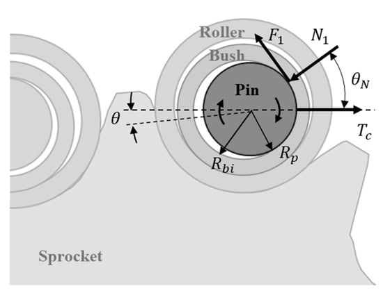
Figure 2.
Schematic of contact for pin articulation.
Hollingworth, N.E. [5] and Hills, D.A. [6] determined that sliding frictional losses during pin articulation are dependent on the pin sliding against the bush. Static or slip motion between the pin and the bush depends on the magnitude of the friction angle of compared with the articulation angle . The frictional force is sufficiently large enough to ensure pin stiction under the condition of tan < tan. In the case of the pin slipping, it should be satisfied with the condition of tan and = tan), where is the friction coefficient between the pin and the bush. The relationship of contact force between the pin and the bush can be written as follows:
Normally, a normal force can be found by integrating the contact pressure over the area. The link tension is then related to the surface contact pressure and area. James B. Spicer [3] calculated pressure related with contact surface between the pin and the bush. It was assumed that the contact pressure is a constant, and the contact angle between the pin and the bush is also a constant. Here, the normal contact force between the pin and the bush is considered to be a normal force. The relationship of contact pressure and normal force is shown as Equation (2), where it is assumed that contact pressure acts radially and is a constant:
Then, friction force between the pin and the bush can be given by Equation (3):
The tension in the chain links owing to centripetal acceleration is considered to have little effect on friction force. The energy losses of pin articulation over the contact area between the pin and the bush are given by:
Figure 3 shows that the chain is driven under lateral offset owing to the derailleur system. The contact force between the pin and the bush with lateral offset angle γ is generated. This analysis differs from that in Kidd [1] and James B. Spicer [3], in that their analysis did not consider the contact of chain links. In fact, contact between the pin and the bush is not generated along the vertical direction of the inner bush surface, but rather occurs at the boundary of the bush plate, shown as normal force in one side and other side due to lateral offset. When the link engages the sprocket, the sliding friction force of pin articulation and are generated. The pressure angles of both normal forces are assumed to be equal, and the normal forces can be expressed as follows:
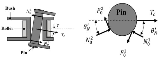
Figure 3.
Schematic of contact for chain links with lateral offset (above view) on the left side and contact of pin articulation (side view) on the right side.
The energy losses of pin articulation with a lateral offset between the pin and the bush are given by:
Figure 4 presents the schematic of forces and motion between the bush and the roller. The tooth contact force transfers to the bush when the roller is engaged with the sprocket tooth. Contact for bush articulation, which is located at the pin-bush contact and the bush-roller contact, is generated. Different from the relationship between the pin and the bush, the surface contact force between the bush and the roller occurred with lateral offset or coplanar offset when the link engages the teeth, due to the independent roller. Therefore, the friction between the pin and the bush, and between the bush and the roller, are generated. is the energy loss of bush articulation owing to friction; is the inner radius of the roller; is the link tension seated in the sprocket; represents the sprocket tooth contact force; β is the nominal pressure angle; and φ is the friction angle for normal contact force between the bush and the roller.
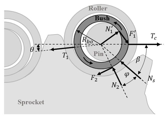
Figure 4.
Schematic of contact for bush articulation.
According to the friction forces, the frictional losses between the pin-bush and the bush-roller can be calculated. The sliding friction force will occur at the bush and roller interface first because it is located at a small radius. Therefore, it is assumed that there is no sliding force between the tooth and rollers, and the friction loss occurs between the roller and the bush. For bush articulation, this is because the tension of the chain in the tight span is much greater than that in the slack span.
For the slip condition of pin articulation, it should be satisfied with the condition of tan , and = tan, where represents the friction coefficient between the bush and the roller. We assume the following:
and
Substituting Equation (7) into Equation (8), the normal contact force between the bush and the roller can be written as follows:
Due to the surface contact of bush articulation, the energy loss between the bush and the roller in the tight span using the relationship between pressure and normal force can be given by the following:
2.2. Damping Force
Viscous damping is an important characteristic in the friction force. The damping coefficient is dependent on lubrication, contacting surface, damping force, and contacting speed. In this study, the magnitude of the damping coefficient refers to the work of Troedsson, I. and Vedmar, L [12]. Power due to damping force in the chain drive system is mainly transmitted through the tight span. In the work of Yu, S. [20] and Lodge, C, J. and Burgess, S, C. [10], magnitude of tension at the slack and tight span were investigated, which showed that tension in the slack span is much smaller than tension in the tight span. Therefore, the damping force is assumed to occur at the tight span, and the damping force in the slack span is neglected, since tension at the tight span is larger than that at the slack span. The damping force is assumed to be proportional to the relative velocity between the end points from the driving sprocket to the driven sprocket at the tight span in Figure 5. Therefore, the damping force is expressed as:
where is the damping coefficient in the tight span of the chain; subscripts 1 and 2 describe the driving and the driven sprocket, respectively; and are the radius of the driving and the driven sprocket, respectively; is the angle between the circle line of the first seated tooth into the links and coordinate line of the driving sprocket; is the angle between the circle line of the last seated tooth into the links and coordinate line of the driven sprocket; is the rotational speed with respect to ; is the rotational speed with respect to ; and and are the chain angles related to the x-axle of the first links in contact with the sprocket in the driving and the driven sprocket, respectively.
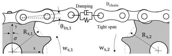
Figure 5.
Schematic of damping force between two sprockets.
2.3. Efficiency of Chain Drive System
The magnitude of the efficiency of the chain drive system is given by the output energy divided by the overall energy, including output energy and transmission loss energy. The total transmission energy losses in the chain drive can be calculated by summing the sliding frictional loss and damping force in the tight span. The sliding friction force includes the coplanar drive transmission, which is calculated as the surface contact pressure and the lateral offset drive, which is the two-points contact.
Using the power of the driven sprocket, the transmission efficiency η of the chain in the coplanar drive can be given by Equation (12):
Transmission efficiency , considering lateral offset, can be written as Equation (13):
where is the chain drive efficiency with the coplanar drive; is the torque of the driven sprocket; and are the rotational speed of the driving and the driven sprocket, respectively; and is the number of teeth on the driving sprocket.
3. Results
The chain system consists of the driving sprocket, the driven sprocket, and the roller chain. The driving sprocket and the driven sprocket are selected with teeth number 32T-32T, which is the maximum ratio in a sprocket, and avoids the chain from falling off of the sprocket due to the lateral offset angle. The type of roller chain is specified in ISO 606 [21]. The friction coefficient for lubricated steel–steel interfaces is assumed to be 0.11 [22]. Driving torque is applied to the driving sprocket, and braking torque is exerted on the driven sprocket. Efficiency was calculated with different parameter values of rotational speed, torque, lateral offset angle, and damping coefficient. The range of parameters is as follows: A rotational speed 40–80 RPM with an interval of 10 RPM, torque 5–9 nm with an interval of 1 nm, a lateral offset angle of 0/0.0174/0.0349/0.0523 rad (0/1/2/3 deg), and a damping coefficient of 40/60/80 ns/m. The list of drive train components and their parameters is presented in Table 1.

Table 1.
Drive train components and parameters for roller chain system.
Figure 6 shows the following: Transmission efficiency as a function of rotational speed and offset angle; the damping coefficient, in which the range of efficiency is 86.3–93.1%; and demonstrates that efficiency decreases with increasing rotational speed and damping coefficient for a given lateral offset angle. In addition, for a given rotational speed, chain efficiency decreases with increasing damping coefficient and lateral offset angle.
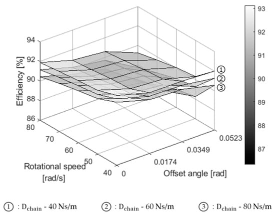
Figure 6.
Transmission efficiency as a function of rotational speed, offset angle, and damping coefficient.
Figure 7 presents the effect of torque, lateral offset angle, and damping coefficient to transmission efficiency, demonstrating that efficiency increases with torque, and the range of efficiency is 90.8–93.0%. Similar to the results from Figure 6, chain efficiency decreases with increasing damping coefficient and offset angle for a given torque.
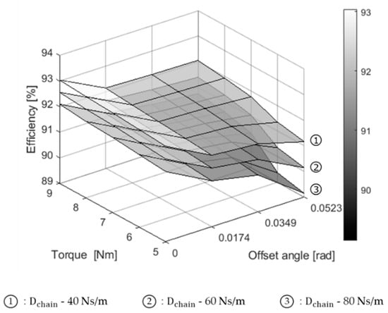
Figure 7.
Transmission efficiency as function of torque, offset angle, and damping coefficient.
4. Experimental Measurement
An experiment is performed in order to measure and verify the estimated efficiency. The layout of the experiment is shown schematically in Figure 8. Driving sprocket axes and driven sprocket axes are connected via the test chain. In the driving sprocket axes, an electric motor with a maximum rotational speed of 1700 RPM and a maximum torque capability of 13 Nm provides propulsion. Driving torque from the electric motor is measured through a torque transducer (accuracy ± 0.3%), which has a rated capacity of 0–100 kgf-m. In the driven sprocket axes, a friction disk brake that can regulate speed and torque is attached. The torque of the driven sprocket axes is measured with the torque transducer of the same type as that with the driving axes. Support bearings are used in the rotational axes between the electric motor, torque transducers, brake disk, and driving/driven sprocket axes. In order to take into consideration friction loss due to support bearings, friction loss of individual support bearings is measured with varying rotational speeds in the range of 50 RPM–280 RPM. The lateral offset angle between sprockets can be adjusted by moving the driven sprocket axes laterally.
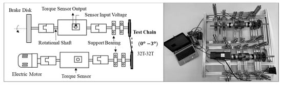
Figure 8.
Schematic of setup and test stand equipment.
Efficiency is measured with different operating conditions. The lateral offset angle is 0/0.0174/0.0349/0.0523 rad with an increment of 1 degree, the torque range is 5–9 Nm with an increment of 1 nm, and the rotational speed is in the range of 40–80 RPM with an increment of 10 RPM. Each test takes approximately 20 s and is repeated seven times.
5. Experiment Results
Figure 9 and Figure 10 show the chain drive efficiency under different conditions (rotational speeds and lateral offset angle) and compares them with theoretical results. The experimental results demonstrate that chain drive efficiency decreased with increasing rotational speed for a given offset angle; whereas, for a given rotational speed, chain drive efficiency decreased with increasing offset angles. It is found that both results exhibit the same tendency in terms of the effect of rotational speed and lateral offset angle. These results agree with the theoretical results. The efficiency is dependent on rotation speed and the offset angle in the Equations (11) and (12). Figure 10 shows the difference between the theoretical and experimental results with an error range of 0.35–1.81%. The results reveal that, when the rotational speed is high, the error value is small. However, error increases with decreasing rotational speed. This is attributable to that, when the test was carried out with low rotational speed and offset angle, vibration and impact occur between the chain and the sprocket.
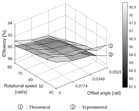
Figure 9.
Transmission efficiency of theoretical and experimental results.
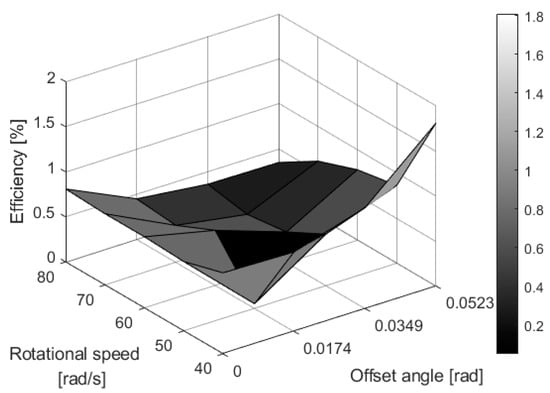
Figure 10.
The difference between theoretical and experimental results.
Figure 11 and Figure 12 show the chain drive efficiency under different output torques and offset angles, and compares them with the theoretical results. The results demonstrate that the chain drive efficiency decreased with increasing output torque for a given offset angle; whereas, for a given output torque, the chain drive efficiency decreased with the increasing offset angle. It is found that both results possess the same trend in terms of the effect of torque and lateral offset angle. Figure 12 presents the difference between theoretical and experimental results, with an error range between 0.23–3.77%. The reason for this is that since the test is carried out with small torque and large offset angle, vibration and impact become more apparent. Thus, the contact surface becomes large between the chain links and sprockets.
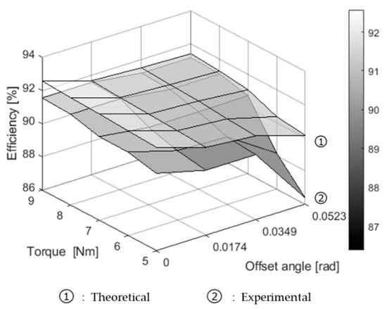
Figure 11.
The transmission efficiency of theoretical and experimental results.

Figure 12.
The difference between theoretical and experimental results.
Figure 13 shows the efficiency under the different center distance between two sprockets axes and a different offset angle and compares them with the theoretical results. The experiment was carried out with an interval of 0.05 m in the test stand. The results demonstrate that the efficiency of the chain drive system increased with decreasing center distance between sprocket axes for a given offset angle. The range of measurement results is 89.34–93.24%.
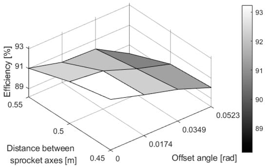
Figure 13.
Chain drive efficiencies for different center distances between sprockets with an offset angle.
6. Conclusions
A novel approach for estimating chain transmission efficiency, which takes into account combined sliding friction losses due to pin articulation, bush articulation, and damping force in the tight span, was proposed. The frictional losses due to pin articulation motion and bush articulation motion were calculated according to Coulomb’s law of friction. The dynamics model was applied to investigate chain links with lateral offset owing to the derailleur system. The damping force, which exists between the driving sprocket and driven sprocket in the tight span, was also considered according to the choice of damping coefficient.
The theoretical value of chain transmission efficiency was calculated with a range of 86.3–93.1%, depending on the driving conditions. Transmission loss in each parameter was analyzed by the various operation conditions of the chain drive system, including rotational speed, torque, lateral offset angle, and damping coefficient. Tests were performed to measure efficiency and compared with the theoretical results, with a difference range of 0.23–3.77%, which demonstrates good agreement with theoretical values.
Author Contributions
T.-O.T. conceived and designed the experiments; S.-P.Z. performed the experiments, analyzed the data and wrote the paper. All authors have read and agreed to the published version of the manuscript.
Funding
This work was supported by Ministry of Trade, Industry and Energy (20001447).
Conflicts of Interest
The authors declare no conflict of interest.
References
- Kidd, M.D.; Loch, N.E.; Reuben, R.L. Experimental Examination of Bicycle Chain Forces. Exp. Mech. 1999, 39, 278–283. [Google Scholar] [CrossRef]
- Conwell, J.C.; Johnson, G.E. Experimental investigation of link tension and roller-sprocket impact in roller chain drives. Mech. Mach. Theory 1995, 31, 533–544. [Google Scholar] [CrossRef]
- James, B.S.; Christopher, J.K.R.; Michael, J.E.; Johanna, R.B.; Masahiko, F.; Masao, T. Effects of Frictional Loss on Bicycle Chain Drive Efficiency. J. Mech. Des. 2001, 123, 598–605. [Google Scholar]
- Wang, C.C.; Tseng, C.H.; Fong, Z.H. A method for improving bicycle shifting performance. Int. J. Vehicle Des. 1997, 18, 100–117. [Google Scholar]
- Hollingworth, N.E.; Hills, D.A. Force in a heavy-duty drive chain during articulation. J. Mech. Eng. Sci. 1986, 200, 367–374. [Google Scholar] [CrossRef]
- Hollingworth, N.E.; Hills, D.A. Theoretical efficiency of a cranked link chain drive. J. Mech. Eng. Sci. 1986, 200, 375–377. [Google Scholar] [CrossRef]
- Jalon, J.G.D.; Bayo, E. Kinematic and Dynamic Simulation of Multibody Systems; Springer: Berlin/Heidelberg, Germany, 1994. [Google Scholar]
- Marques, F.; Flores, P.; Pimenta Claro, J.C.; Hamid, M.L. Modeling and analysis of friction including rolling effects in multibody dynamics: A review. Multibody Syst. Dyn. 2019, 45, 223–244. [Google Scholar] [CrossRef]
- Burgess, S.C. Improving cycling performance with large sprockets. Sports Eng. 1998, 1, 107–113. [Google Scholar] [CrossRef]
- Lodge, C.J.; Burgess, S.C. A model of the tension and transmission efficiency of a bush roller chain. Proc. Inst. Mech. Eng. 2001, 216, 385–394. [Google Scholar] [CrossRef]
- Lodge, C.J.; Burgess, S.C. An investigation into the selection of optimum chain and sprocket size. J. Eng. Des. 2004, 15, 536–580. [Google Scholar] [CrossRef]
- Troedsson, I.; Vedmar, L. A method to determine the dynamic load distribution in a chain drive. Proc. Inst. Mech. Eng. 2001, 215, 569–579. [Google Scholar] [CrossRef]
- Troedsson, I.; Vedmar, L. A method to determine the static load distribution in a chain drive. J. Mech. Des. 1999, 121, 402–408. [Google Scholar] [CrossRef]
- Burgess, S.; Lodge, C. Optimisation of the chain drive system on sports motorcycles. Sports Eng. 2004, 7, 65–73. [Google Scholar] [CrossRef]
- Wragge-Morley, R.; Yon, J.; Lock, R.; Alexander, B.; Burgess, S. A novel pendulum test for measuring roller chain efficiency. Meas. Sci. Technol. 2018, 29. [Google Scholar] [CrossRef]
- Egorov, A.; Kozlov, K.; Belogusev, V. A method for evaluation of the chain drive efficiency. J. Appl. Eng. Sci. 2015, 34, 13–14. [Google Scholar] [CrossRef]
- Kozlov, K.; Belogusev, V.; Egorov, A.; Syutov, N. Development of method of evaluate friction losses of chain drives. In Proceedings of the 17th International Scientific Conference Engineering for Rural Development, Jelgava, Latvia, 23–25 May 2018; pp. 930–936. [Google Scholar]
- Egorov, A.; Kozlov, K.; Belogusev, V. Experimental identification of the electric motor moment of inertia and its efficiency using the additional inertia. ARPN J. Eng. Appl. Sci. 2016, 11, 10582–10588. [Google Scholar]
- Kozlov, K.E.; Egorov, A.V.; Belogusev, V.N. Experimental evaluation of chain transmissions lubricants quality using a new method based on additional inertia moment use. Procedia Eng. 2017, 206, 617–623. [Google Scholar] [CrossRef]
- Huo, J.; Yu, S.; Yang, J.; Li, T. Static and dynamic characteristic of the chain drive system of a heavy duty apron feeder. Open Mech. Eng. J. 2013, 7, 121–128. [Google Scholar] [CrossRef]
- Short-Pitch Transmission Precision Roller and Bush Chains: Attachments and Associated Chain Sprockets; ISO606; ISO: Vernier, Switzerland, 2015.
- Lee, C.H.; Polycarpou, A.A. Static Friction Experiments and Verification of an Improved Elastic-Plastic Model Including Roughness Effects. J. Tribol. 2007, 129, 754–760. [Google Scholar] [CrossRef]


Publisher’s Note: MDPI stays neutral with regard to jurisdictional claims in published maps and institutional affiliations. |
© 2020 by the authors. Licensee MDPI, Basel, Switzerland. This article is an open access article distributed under the terms and conditions of the Creative Commons Attribution (CC BY) license (http://creativecommons.org/licenses/by/4.0/).