Article

Development of Mathematical Models in Explicit Form for Design and Analysis of Axial Flux Permanent Magnet Synchronous Machines

Faculty of Energy Technology, University of Maribor, Hočevarjev trg 1, 8270 Krško, Slovenia
*
Author to whom correspondence should be addressed.
Appl. Sci. 2020, 10(21), 7695; https://doi.org/10.3390/app10217695
Submission received: 5 October 2020 / Revised: 19 October 2020 / Accepted: 21 October 2020 / Published: 30 October 2020

Abstract

:
This article proposes a methodology for the design of double-sided coreless axial flux permanent magnet synchronous machines, which is based on a developed model for calculating the axial component of the magnetic flux density in the middle of the distance between opposite permanent magnets, which also represents the middle of the stator. Values for different geometric parameters represent the input data for the mathematical model in explicit form. The input data are calculated by using a simplified finite element method (FEM), which means that calculations of simplified 3D models are performed. The simplified model consists of two rotor disks with surface-mounted permanent magnets and air between them, instead of stator windings. Such a simplification is possible due to similar values of permeability of the air and copper. For each simplified model of the machine the axial component of the magnetic flux density is analyzed along a line passing through the center of opposite permanent magnets and both rotor disks. Values at the middle of the distance between the opposite permanent magnets are the lowest and are therefore selected for the input data at different stator, rotor disks and permanent magnets (PM) thicknesses. Such input data enable the model to consider the nonlinearity of materials.

1. Introduction

Stators of axial flux permanent magnet synchronous machines (AFPMSMs) can be constructed with or without ferromagnetic cores [1].
Coreless topologies are used for low- and medium-power generators [2]. This article deals with a coreless double-sided AFPMSM with surface-mounted permanent magnets (PMs) on the massive ferromagnetic material of two external rotor disks.
The advantages of coreless topologies are the absence of a cogging torque [3] and the use of a massive instead of a laminated iron core in rotor discs. Due to the absence of losses in the ferromagnetic core of the stator, this topology can operate at a higher efficiency [4] compared to the conventional machines [3,5,6].
Torque and induced voltage sizes are mainly limited by:
  • outer dimensions of the machine and its mass and
  • current density in the windings.
The maximum permissible external dimensions of the machine limit the space for the installation of coils and permanent magnets, and the maximum allowed temperature limits the current density in the windings [5,7], whereby the torque and induced voltage depend on the active volume of the copper of the winding, the volume of permanent magnets and of the current density in the windings [8].
The volume of PMs determines the magnetic flux density in the air gap, and is determined by their thickness, by the number of poles of the machine, and by the external and internal radii of the active winding volume of the machine [9].
Magnetic flux density in the air gap also depends on the thickness of the stator, as it determines the distance between the opposite PMs. This distance together with the volume (dimensions) of PMs also influence the size of the attraction forces between the rotor disks [10], with which the thickness of the rotor disks is determined [2].
Induced voltage also depends on the magnetic flux density in the air gap, more precisely from the axial component of the magnetic flux density which passes between the opposite permanent magnets [11]. This dependence is written with the help of Faraday’s induction law based on a variable magnetic flux which perpendicularly passes through the coil [3].
From the above we can conclude that the magnetic flux density in the air gap is one of the key factors [12] to produce torque and the induced voltage [13], since it is directly related to all the dimensions and materials in the machine. Therefore, the calculation of the magnetic flux density is a priority task in the design of the machine.
The distribution of the magnetic field in the AFPMSM can be determined using analytical and numerical methods among which the finite element method (FEM) is most commonly used. The advantage of calculations using the FEM is the higher accuracy of the results, but the weakness is in the longer required time for individual calculations [9].
Analytical methods are not time-consuming, but they have a disadvantage in that it is difficult to accurately capture all three dimensions of the distribution of the magnetic field in the machine [14].
There are many different approaches for the analysis of magnetic fields in the scientific literature. Here, only methods that are based on the middle radius of the machine, (i.e., PMs) are presented, since the methodology presented in this article is also based on the average radius of the machine.
The authors of [15] present the analytical model of an ironless one-sided AFPMSM, based on the distribution of the magnetic field in the medium radius. To determine the magnetic scalar potential, Laplace equations are solved in a Cartesian coordinate system using the Fourier-type method. To confirm the method and the accuracy of the results 2D analysis with FEM is also performed, which indicates that the deviation of the analytically obtained results is within 3% compared to the results obtained with FEM.
In [16], the analytical model of a coreless AFPMSM is presented for the calculation of the magnetic field in the air gap, which is based on the distribution of the magnetic field in the average radius of the machine (PMs). The authors note that the effects of curvature and the marginal (edge) effects of the machine on the magnetic flux must be considered. Azzouzi and others in [17] represent a unique solution for the calculation of a magnetic field with an average radius of the slotted AFPMSM under no load conditions. The effects of curvature and marginal (edge) effects are considered by a function, which is derived from the 3D FEM analysis.
Due to the shortcomings of the models based on the distribution of the magnetic field at the middle radius, the authors use “multilayer” models. This means that 2D models are calculated on different radii, thus considering the effects of curvature. To calculate quantities such as machine torque, the accumulated results of all layers [18,19,20] are considered.
In order to determine the distribution of the magnetic flux density in a coreless AFPMSM, a “multilayer” analytical model is proposed in [17,18], where the authors also considered the radial dependence of the excitation (the constant width of the winding side). In [21], an analytical model for the calculation of the magnetic field in the air gap of a slotted AFPMSM is presented. The particularity of the method is that the model is assembled for a slotless machine and these are later considered through the magnetic conductivity function. Iron losses were separately calculated by means of a nonlinear reluctance circuit.
This article is the continuation of research presented in [22,23] and proposes a new methodology for design of double-sided coreless AFPMSM, which is based on a developed model for calculating the axial component of the magnetic flux density in the middle of the stator with two air gaps (in the middle of the distance between opposite permanent magnets). The input data for the mathematical model are summarized by an approximation method and include the effects of stator thicknesses, rotor thicknesses, PM thicknesses as well as the nonlinearity of the rotor disks.

2. Materials and Methods

AFPMSMs can be designed using analytical or numerical methods (FEM) [19].
FEM is used for solving complex problems, where the method usually uses magnetic potentials and divides two-dimensional (2D) or three-dimensional (3D) models of the machine to a limited number of elements.
The initial model of the machine can be determined, with a known magnetic circle and current in the windings (dimensions of PMs, rotor disks, air gap and stator), using a set of general equations, also known as “Sizing equations” [9,24,25,26,27].
This model is then used as a starting point for more accurate calculations of individual parameters using FEM [28,29].
Using FEM for designing AFPMSMs is oftentimes consuming both in the construction of the model itself and in the computation time [3,30,31,32,33]. So far, published scientific papers deal with the solution of this problem through the development of analytical methods [18,27,29,30,31,32,33,34,35,36], whose derivations are often mathematically demanding and require certain simplifications and assumptions [37,38,39], which on one side influences the accuracy of the analytical model and on the other side enables a faster calculation by means of derived equations for the magnetic flux density in an explicit form [40].
The presented methodology uses simplified FEM calculations for the initial dataset. A simplified 3D model was constructed in Ansys Maxwell software, where instead of the stator only air was included. This simplification was chosen due to the similarity of the permeabilities of air and copper.
Simplified calculations with FEM were performed at various stator thicknesses with two air gaps, with particular interest in the values of the axial component of the magnetic flux density in the middle of the stator, since at this point the magnetic flux density is the lowest, which gives us reliable starting points for further and more-accurate calculations.
In the first step of the design, the types of PMs and their shapes and dimensions are usually chosen, as they have the greatest influence on the magnetic flux density in the air gap. The density of the magnetic flow in the air gap is mainly influenced by the thickness of the stator, the width of the two air slots, and thus the distance between the TM between the two disks and the thickness of the rotor discs.

2.1. Simplified FEM Calculations

The initial FEM analysis of the machine is represented by simplified FEM calculations aimed at determining the size of the axial component of the magnetic flux density along a line that extends between both rotor discs through the center of gravity of PMs. The simplification is that the calculations were performed without considering the windings; only the air between the opposite rotor disks with surface-mounted PM was considered, since the permeability of air and copper is almost the same.
Figure 1a shows the initial AFPMSM model consisting of two rotor disks, 20 permanent magnets and a 100 mm virtual air gap (distance between PMs on opposite rotor disks), which consists of 20 layers. For each layer of the virtual air gap, a simplified calculation with FEM was performed, analyzing the axial component of the magnetic flux density across the virtual line passing through both the rotor disks, the virtual air gap, and the PMs on opposite rotor disks (through the center of gravity). The position of the line is shown in Figure 1b.
Figure 2 shows an example of the axial component of the magnetic flux density (Bz) along the centerline (shown in Figure 3) with a 55-mm virtual air gap thickness.
The values of the axial component of the magnetic flux density, Bz_max and Bz_min, are shown, which represent the value of Bz near the PM (Bz_max) and in the middle of the virtual air gap (Bz_min). Values in the middle of the virtual air gap represent the initial set of input data for development of the mathematical model in explicit form for the calculation of the value of axial component of magnetic flux density in the middle of the virtual air gap and consequently in the middle of the stator.
Simplified FEM calculations were performed with limitations, such as the condition that stator (virtual air gap) thickness is not larger the 4 times the PM thickness (ds ≤ 4hTM). Initial simplified FEM calculations were performed for the 3-phase AFPMSM with the data shown in Table 1 [41] and again repeated for the AFPMSM with the data shown in Table 2.

2.2. Least Square Approximation Method

Values for Bz_min were used to produce a polynomial using a least square approximation (LSA) method. This is a mathematical procedure that can find a curve that fits best to a known set of given points by minimizing the sum of the squares of the offsets (“the residuals”) of the points from the curve [42]. The sum of the squares of the offsets was used instead of the offset absolute values because this allows the residuals to be treated as a continuous differentiable quantity [43]. Vertical least squares fitting proceeds by finding the sum of the squares of the vertical deviations R2 of a set of n data points [43], which is presented in Equation (1).
R 2 i = 1 n y i f x i , a 1 , a 2 , , a n 2
where R is the residual, yi is the data point calculated using simplified FEM, f is the fitting function, xi is an independent variable of the fitting function, and a1, a2, and an are coefficients of the fitting function. In our case the polynomial was chosen as a fitting function.
Different order functions were used in order to determine the best fitting polynomial. Since three parameters were considered (stator thickness, rotor thickness and PM thickness) a function with 3 unknowns must be included (Figure 3).
Using the procedure described above, a mathematical model in explicit form was obtained for the calculation of the axial component of magnetic flux density in the middle of the stator, where PM thickness (from 5 to 10 mm), stator (up to 4 times PM thickness) and rotor disk thickness (from 4 to 15 mm) was considered (Equation (2)):
B z = 0.06584 2.59175 10 8 d + 0.06379 h P M + 0.15354 d F e + 0.00065 d 2 0.00228 d h P M 0.00771 d d F e + 0.01742 h P M d F e 0.00779 h P M 2 0.01836 d F e 2 1.50319 10 5 d 3 6.64056 10 5 d 2 h P M + 0.00013 d 2 d F e + 0.00048 d h P M 2 3.95197 10 5 d h P M d F e + 0.00036 d d F e 2 0.00113 h P M 2 d F e + 0.00032 h P M 3 0.00053 h P M d F e 2 + 0.00092 d F e 3 + 9.49058 10 8 d 4 + 8.87146 10 7 d 3 h P M 8.12445 10 7 d 3 d F e 3.50659 10 8 d 2 h P M 2 1.1743 10 6 d 2 h P M d F e 2.2058 10 5 d h P M 3 + 1.10169 10 5 d h P M 2 d F e 6.55623 10 6 d h P M d F e 2 + 3.20094 10 6 h P M 3 d F e + 6.93144 10 6 h P M 4 + 4.3272 10 5 h P M 2 d F e 2 6.49819 10 6 h P M d F e 3 2.44857 10 6 d 2 d F e 2 4.07463 10 6 d d F e 3 1.59859 10 5 d F e 4
where Bz is the axial component of magnetic flux density in the middle of the stator, d is the thickness of the stator with two air gaps, hPM is the thickness of the PMs and dFe is the thickness of the rotor disks.
As is was mentioned above, the mathematical model is derived from the input data obtained by the simplified FEM, which was conducted with limitations, such as the condition that stator (virtual air gap) thickness is not larger than 4 times the PM thickness (ds ≤ 4 hTM) and with the PM span selected in such way that it covers 120° electrical. These limitations are selected on the basis of FEM analysis results, which are shown in Section 3.

2.3. Design and Analysis of AFPMSM

Designing AFPMSMs, as well as other typologies of drives, has steps. The first step is usually determined by requirements or constraints such as required torque size, speed, maximum permissible dimensions of the machine, cooling method and maximum induced voltage. Therefore, at the beginning of this process, the required dimensions of the machine, especially the internal diameter of the installation of permanent magnets and windings, the external diameter of the machine (rotor and stator) and the axial length of the machine must be specified as accurately as possible.
To determine these parameters, the standard approach is to use the so-called sizing equations [7,26]. Two types of sizing equations can be found in the scientific literature [44].
The first type is a classical equation (Equation (3)) which considers the outer diameter and the axial length of the machine [27] when calculating the output power of the machine Pi (in addition to the electric and magnetic parameters), where i(t) is phase electrical current, m is the number of phases, e(t) the open circuit-induced voltage (phase value), η the efficiency of the machine, Kp the electric power shape factor, T is one period of induced voltage, and Epk and Ipk are peak values of the induced voltage and phase current [27].
P i = η m T 0 T e t i t d t   = η m K p E p k I p k
The emphasis of this article is on the second type of sizing equation, which refers to the connection between the electromagnetic torque and the basic geometric, electrical and magnetic parameters (Equation (4)) [45].
T e m = 2 π B z A i λ 1 λ 2 R o 3
In Equation (4), Tem is electromagnetic torque, Bz the axial component of magnetic flux density, Ai the average electric load on the radius that matches the inner radius of PMs, Ro the outer PM radius, Ri the inner PM radius and λ the ratio between the inner and outer PM radius.
This equation was first introduced in [45], and since then it has been widely used [9,21,46], since it is generally useful. From this equation we can detect the magnetic shear stress when divided by the active surface of the rotor. In the presented form, it achieves greater accuracy in the case of a trapezoidal distribution of the magnetic flux density and at higher values of electrical current through areas where the magnetic flux density is maximal. It is also possible to determine the torque density by dividing the equation with the mass of active machine parts (Nm/kg) or the total machine volume (Nm/m3).
After completing the evaluation of the main geometric parameters, the design process can be continued according to the standard steps [9,44], which are presented below.
The number of the machine’s synchronous revolutions according to Equation (5), can be determined:
n s = 60 f p
where ns is the synchronous speed of the machine, f the network frequency and p the number of pole pairs. It can be seen that the higher number of poles of the machine is required for lower synchronous rotations.
The winding factor (kw) is determined by the geometric method, from the ratio between the geometric (egeometric) and arithmetic (earithmetic) value of the induced voltage (Equation (6)) [23].
k w = e g e o m e t r i c e a r i t h m e t i c
Saturation factor (ksat) is determined by Equation (7) [11]:
k s a t = 1 + l F e 2 μ r d a g + 0.5 d F e
where lFe is the magnetic flux path in the iron, dag the air gap thickness (between rotor and stator), dFe the rotor disk thickness and μr the relative permeability of steel.
Axial component of magnetic flux density (Bz) is determined by Equation (8) [9]:
B z = B r 1 + μ r e c d a g + 0.5 d s h P M k s a t
where Br is the remanent magnetic flux density, dag the air gap thickness (between rotor and stator), ds the stator thickness, μrec the recoil permeability, hPM the PM thickness and ksat the saturation factor.
Ratio between PM pitch and pole pitch (αi) is independent of the radius and can be written as Equation (9) [9]:
α i = τ P M τ p
where τp is the pole pitch and τPM the PM pitch.
Magnetic flux (Φ), induced voltage and electromagnetic torque can be determined using Equations (10)–(12), respectively [9]:
Φ = α i B z π 8 p D o 2 D i 2
E = π 2 f N 1 k w Φ
T e m = 1 4 α i m I a N 1 k w B z D o 2 D i 2
where Bz is the axial component of magnetic flux density, p the number of poles, Do and Di the outer and inner PM diameter, E the induced voltage, f the network frequency, N1 the number of turns per coil, kw the winding factor, Φ the magnetic flux, Tem the electromagnetic torque, αi the PM pitch-to-pole pitch ratio, m the number of phases, and Ia the effective value of stator current.

3. Results and Discussions

3.1. Influence of Different Geometrical Parameters on Characteristics of the Machine

In this section, firstly the influence of PM thickness and rotor disk thickness on the axial component of magnetic flux density is calculated by using simplified FEM. Additionally, the influence of PM span and stator thickness on torque and induced voltage of the machine was analyzed by using the 3D FEM.
Figure 4 shows the influence of PM thickness on the Bz size in the middle of the stator for the machine described in Table 1. This analysis was carried out using simplified FEM.
It can be seen in Figure 4 that the PM thickness has a significant influence on the size of the axial component of magnetic flux density and on its degree of changing with the increase in the distance between PMs on opposite rotor disks.
Figure 5 shows the influence of rotor disk thickness on the Bz size in the middle of the stator for the machine described in Table 1. This analysis was also carried out using the simplified FEM.
Figure 5 shows that rotor disks thickness also influences the size of the axial component of magnetic flux density up to a specific thickness. This is the reason that the rotor disk thickness has to be carefully selected. When designing the machine, namely rotor disks, the thickness has to be carefully selected in order to withstand the pull forces from the PMs (to keep the air gap constant and prevent the deflection of rotor disks) on one hand and on the other hand it influences the total weight of the machine and its efficiency.
Since some characteristics of the machine, namely waveforms, cannot be analyzed by the simplified FEM, a regular 3D FEM analysis was performed where PM span and stator thickness influence were analyzed.
Figure 6 and Figure 7 show the influence of PM span on the torque and induced voltage for the machine described in Table 1 and Figure 8 shows the influence of stator thickness on the torque size of the machine.
Figure 6 shows that PM span has a positive influence of the torque size of the machine, since the torque value increases with the increase in PM span. As we can see in Figure 7, the PM span increase has a different influence on the induced voltage of the machine. Its value does not change significantly, but its waveform does. We can see that for higher PM spans the induced voltage waveform has a flat top and for lower PM spans it has a more triangle-shaped waveform. It can be noticed that for 24° PM span the induced voltage has a sinusoidal waveform. That is the reason for all the input data for the derivation of the mathematical model being obtained with the simplified FEM calculations of a model with a 24° PM span (it covers 120° electrical).
When we derived the mathematical model, we also stated that the ratio between stator and PM thickness can be up to 1:4. Figure 8 shows the reason for this limitation, since the torque value increase rate reduces with the increase in the stator thickness.

3.2. Design and Analysis of AFPMSM

Two coreless AFPMSM were designed (described in Table 1 and Table 2) by three methods, namely an analytical method (Equations (6)–(12)), and a combination of an analytical method and mathematical models in explicit form and FEM (Ansys Maxwell 3D).
Results of the design by analytical method are shown in Table 3, where different stator, rotor and PM thicknesses were considered. Table 4 shows the results of combination of the analytical method and mathematical models in explicit form and Table 5 shows the results gained by FEM as well as the comparison of the results of all three methods.
Table 5 shows that all three used methods produce similar results with minor deviations at certain points. For the selected parameters of the AFPMSM, the matching of the results of the torque size of the analytical method and FEM is 102.98% and between the mathematical model in explicit form and FEM is 98.54%.
Matching of the induced voltage between the analytical method and FEM is 93.62% and between the mathematical model in explicit form and FEM is 97.91%.
The procedure of designing was repeated for the 20-pole AFPMSM, described in Table 2 with the same rotor disk thicknesses used for the AFPMSM in Table 1. A new mathematical model with new input data for different pole number was produced for this purpose by the same procedure as presented in the previous section.
Table 6 shows the comparison of the torque size, calculated by using three different methods for designing AFPMSMs.
For the selected parameters, the matching of the results between the analytical method and FEM is 132.14% and between the mathematical model in explicit form and FEM is 95.43%. It can be seen that the mathematical model in explicit form produces more accurate results for PM thicknesses hPM = 5 mm and hPM = 7 mm in comparison with the analytical method. The reason for that can be found in the fact that the analytical method does not consider the PM span, but it works under the assumption that the PM surface and air gap surface are the same.
For hPM = 10 mm, neither the analytical method nor mathematical model in explicit form produce accurate results compared to the gained FEM results. The reason for this is in the magnetic flux leakage, since the PM thickness is larger than the distance between adjacent PMs on the same rotor disk (hPM > lPM). These dimensions are also shown in Figure 9.
Figure 9 shows the 2D model of the coreless double-sided AFPMSM with dimensions and flux paths, where Path 1 represents the mean path of the magnetic flux and Paths 2 and 3 represent the magnetic flux leakage. PM dimensions and the stator and rotor disk thicknesses influence the size of the magnetic flux and its leakage. If the PM thickness is too small or stator thickness is too high, the magnetic flux leakage can increase in Path 2 and in the case of higher PM spans in Path 3.
In the case of hPM = 10 mm, the magnetic flux leakage between adjacent PMs on the same rotor disk increases (Path 3). This leakage is also increased by increasing the stator thickness, due to the magnetic flux path enclosing in Path 3 and the decreasing share of magnetic flux in Path 1.
In Table 6, it can also be seen that the developed mathematical model in explicit form produces accurate results for the stator thickness ds = 20 mm, which represents twice the PM thickness. For larger stator thicknesses magnetic flux leakage increases and the developed mathematical model in explicit form does not consider it, since it only considers the axial component of magnetic flux density in the middle of the stator.

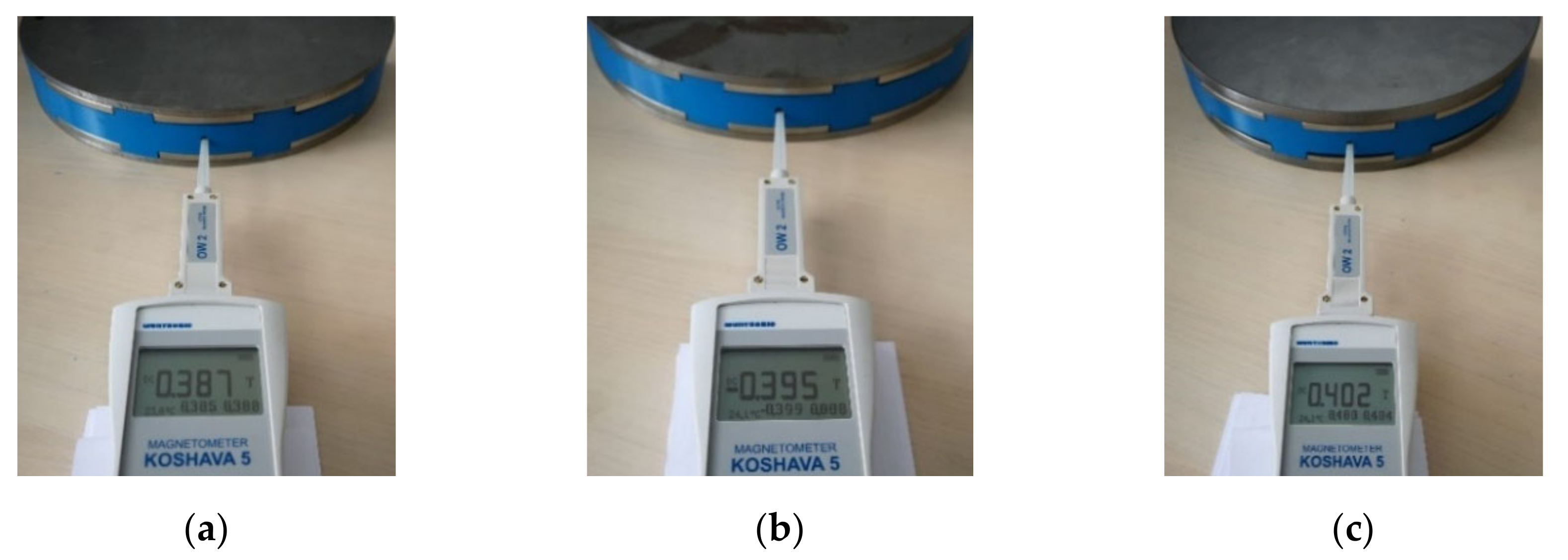
3.3. Laboratory Measurements

Laboratory measurements were performed on the prototype AFPMSM with the data presented in Table 1. Measurements of the torque size for different loadings were performed as well as the induced voltage measurements at different rotation speeds.
Table 7 shows the measured values of induced voltages in individual phases of the machine and average value for all three phases at different rotation speeds.
Table 8 shows the comparison of average measured values of induced voltages and calculated values using the analytical method and developed mathematical model in explicit form.
Table 9 shows the comparison of measured values of torque at different electrical current values and comparison with the calculated values, using the analytical method and developed mathematical model in explicit form.
Table 8 and Table 9 show that the developed mathematical model is accurate, since the matching of the measured values of torque and induced voltage are in good agreement with the calculated results. Some deviation is present in the matching of the results which may be caused by the measuring equipment. For this purpose, we measured the axial component of magnetic flux density in the middle of the distance between PMs on opposite rotor disks.
To measure the axial component of magnetic flux density (Bz) in the middle of the distance between PMs on opposite rotor disks we developed a special tool that enables the PMs to stay in their position and measure the values at exact positions. Two tools were modeled and 3D printed (one 17 mm thick and one 22 mm thick). Figure 10a shows the model of the tool with the location of the opening where the measuring probe (Magnetometer KOSHAWA 5 with the magnetic probe) will be inserted and Figure 10b shows the printed tool. The measuring probe is inserted into the opening, which is printed to the middle radius of the PMs.
Figure 11 shows the printed tool (d = 22 mm) with mounted PMs and the measuring procedure of the axial component of magnetic flux density (Bz) at the middle of the distance between opposite PMs (on Path 1 in Figure 9), with PM thickness hPM = 5 mm and different rotor disk thicknesses.
Results of the measurements of the axial component of magnetic flux density (Bz) for different rotor disk thicknesses and two stator thicknesses are shown and compared to the calculated values (using FEM and the developed mathematical model) in Table 10.
Table 10 also shows the accuracy of the presented methodology, since the average matching between the measured values and calculated values is 96.92%.

4. Conclusions

The article presents a complete procedure for the development of the mathematical models in explicit form for the calculation of Bz in the middle of the stator of a double-sided coreless AFPMSM. The developed model simultaneously considers the influence of the thicknesses of rotor disks, PMs and stators along with the nonlinearity of the materials.
The FEM, of course, also considers the nonlinearity of the materials, but it is often a time-consuming method, since in the changes of geometric parameters it is necessary to compile and calculate a new model of the machine. The developed mathematical model consists of input data, which are determined using simplified FEM calculations and already consider the different geometrical parameters of the machine (ds, hPM and dFe), so they do not require new long-lasting calculations.
In addition to the results of calculations with the FEM, we can see that the measurements also confirm the accuracy of the methodology.

Author Contributions

Conceptualization, F.P. and P.V.; methodology, F.P. and P.V.; software, F.P.; validation, F.P. and P.V.; formal analysis, F.P.; investigation, F.P.; resources, F.P.; data curation, F.P.; writing—original draft preparation, F.P.; writing—review and editing, F.P. and P.V.; visualization, F.P.; supervision, P.V. All authors have read and agreed to the published version of the manuscript.

Funding

This research received no external funding.

Conflicts of Interest

The authors declare no conflict of interest.

References

  1. Mirsalim, M.; Yazdanpanah, R.; Hekmati, P. Design and analysis of double-sided slotless axial-flux permanent magnet machines with conventional and new stator core. IET Electr. Power Appl. 2015, 9, 193–202. [Google Scholar] [CrossRef]
  2. Caricchi, F.; Crescimbini, F.; Mezzetti, F.; Santini, E. Multistage axial-flux PM machine for wheel direct drive. IEEE Trans. Ind. Appl. 1996, 32, 882–888. [Google Scholar] [CrossRef]
  3. Virtic, P.; Pisek, P.; Marcic, T.; Hadziselimovic, M.; Stumberger, B. Analytical Analysis of Magnetic Field and Back Electromotive Force Calculation of an Axial-Flux Permanent Magnet Synchronous Generator with Coreless Stator. IEEE Trans. Magn. 2008, 44, 4333–4336. [Google Scholar] [CrossRef]
  4. Lombard, N.; Kamper, M.J. Analysis and performance of an ironless stator axial flux PM machine. IEEE Trans. Energy Convers. 1999, 14, 1051–1056. [Google Scholar] [CrossRef]
  5. Daghigh, A.; Javadi, H.; Torkaman, H. Improved design of coreless axial flux permanent magnet synchronous generator with low active material cost. In Proceedings of the 6th Power Electronics, Drive Systems & Technologies Conference (PEDSTC2015), Tehran, Iran, 3–4 February 2015; pp. 532–537. [Google Scholar] [CrossRef]
  6. Javadi, S.; Mirsalim, M. A Coreless Axial-Flux Permanent-Magnet Generator for Automotive Applications. IEEE Trans. Magn. 2008, 44, 4591–4598. [Google Scholar] [CrossRef]
  7. Chen, A.; Nilssen, R.; Nysveen, A. Performance comparisons among radial flux, multi-stage axial flux and three-phase transverse flux PM machines for downhole applications. In Proceedings of the IEEE International Electric Machines and Drives Conference, Miami, FL, USA, 3–6 May 2009; pp. 1010–1017. [Google Scholar]
  8. Hanselman, D. Brushless Permanent Magnet Motor Design; The Writers’ Collective: Cranston, RI, USA, 2003. [Google Scholar]
  9. Gieras, J.F.; Wang, R.J.; Kamper, M.J. Axial Flux Permanent Magnet Brushless Machines; Kluwer Academic Publishers: Dordrecht, Germany, 2004. [Google Scholar]
  10. Mueller, M.A.; McDonald, A.S.; MacPherson, D.E. Structural analysis of low-speed axial-flux permanent-magnet machines. IEE Proc. Electr. Power Appl. 2005, 152, 1417–1426. [Google Scholar] [CrossRef]
  11. Jara, W.; Martín, A.; Tapia, J.A. Axial flux PM machine for low wind power generation. In Proceedings of the XIX International Conference on Electrical Machines—ICEM 2010, Rome, Italy, 6–8 September 2010; pp. 1–5. [Google Scholar] [CrossRef]
  12. Daghigh, A.; Javadi, H.; Javadi, A. Improved Analytical Modeling of Permanent Magnet Leakage Flux in Design of the Coreless Axial Flux Permanent Magnet Generatorx. Can. J. Electr. Comput. Eng. 2017, 40, 3–11. [Google Scholar]
  13. Caricchi, F.; Crescimbini, F.; Honorzti, O.; Bianco, G.L.; Santini, E. Performance of coreless-winding axial-flux permanent-magnet generator with power output at 400 Hz-3000 rev/min. In Proceedings of the IAS ’97 Conference Record of the 1997 IEEE Industry Applications Conference Thirty-Second IAS Annual Meeting, New Orleans, LA, USA, 5–9 October 1997; Volume 1, pp. 61–66. [Google Scholar]
  14. Wang, Y.; Chen, W.X.C.; Dong, Z. A parametric magnetic network model for axial flux permanent magnet machine with coreless stator. In Proceedings of the 17th International Conference on Electrical Machines and Systems (ICEMS), Hangzhou, China, 22–25 October 2014; pp. 1108–1113. [Google Scholar] [CrossRef]
  15. Chan, T.F.; Lai, L.L.; Xie, S. Field Computation for an Axial Flux Permanent-Magnet Synchronous Generator. IEEE Trans. Energy Convers. 2009, 24, 1–11. [Google Scholar] [CrossRef]
  16. Bumby, J.R.; Martin, R.; Mueller, M.A.; Spooner, E.; Brown, N.L.; Chalmers, B.J. Electromagnetic design of axial-flux permanent magnet machines. Proc. Inst. Elect. Eng. Elect. Power Appl. 2004, 151, 151–160. [Google Scholar] [CrossRef]
  17. Azzouzi, J.; Barakat, G.; Dakyo, B. Quasi-3D analytical modeling of the magnetic field of an axial flux permanent magnet synchronous machine. In Proceedings of the IEEE International Electric Machines and Drives Conference, IEMDC’03, Madison, WI, USA, 1–4 June 2003; IEEE: Piscataway, NJ, USA, 2003; Volume 3, pp. 1941–1947. [Google Scholar] [CrossRef]
  18. Virtic, P.; Pisek, P.; Hadziselimovic, M.; Marcic, T.; Stumberger, B. Torque Analysis of an Axial Flux Permanent Magnet Synchronous Machine by Using Analytical Magnetic Field Calculation. IEEE Trans. Magn. 2009, 45, 1036–1039. [Google Scholar] [CrossRef]
  19. Tiegna, H.; Bellara, A.; Amara, Y.; Barakat, G. Analytical Modeling of the Open-Circuit Magnetic Field in Axial Flux Permanent-Magnet Machines with Semi-Closed Slots. IEEE Trans. Magn. 2012, 48, 1212–1226. [Google Scholar] [CrossRef]
  20. Marignetti, F.; Di Stefano, R. Electromagnetic Analysis of Axial-Flux Permanent Magnet Synchronous Machines with Fractional Windings with Experimental Validation. IEEE Trans. Ind. Electron. 2011, 59, 2573–2582. [Google Scholar] [CrossRef]
  21. Caricchi, F.; Crescimbini, F.; Honorati, O.; Di Napoli, A.; Santini, E. Compact wheel direct drive for EVs. IEEE Ind. Appl. Mag. 1996, 2, 25–32. [Google Scholar] [CrossRef]
  22. Pranjić, F.; Virtič, P. Determination of an Optimum Fictitious Air Gap and Rotor Disk Thickness for a Coreless AFPMM. Teh. Vjesn. 2018, 25, 1731–1738. [Google Scholar] [CrossRef]
  23. Pranjic, F.; Virtic, P. Designing Rotor Disks of a Coreless Axial Flux Permanent Magnet Machines by Using Simplified FEM and an Approximation Method. IEEE Trans. Energy Convers. 2020, 35, 1505–1512. [Google Scholar] [CrossRef]
  24. Kahourzade, S.; Mahmoudi, A.; Rahim, N.A.; Ping, H.W. Sizing equation and Finite Element Analysis optimum design of axial-flux permanent-magnet motor for electric vehicle direct drive. In Proceedings of the IEEE International Power Engineering and Optimization Conference, Melaka, Malaysia, 6–7 June 2012; pp. 1–6. [Google Scholar] [CrossRef]
  25. Rallabandi, V.; Taran, N.; Ionel, D.M.; Eastham, J.F. On the feasibility of carbon nanotube windings for electrical machines—Case study for a coreless axial flux motor. In Proceedings of the IEEE Energy Conversion Congress and Exposition (ECCE), Milwaukee, WI, USA, 18–22 September 2016; pp. 1–7. [Google Scholar]
  26. Kalender, O.; Ege, Y.; Nazlibilek, S. Design and determination of stator geometry for axial flux permanent magnet free rod rotor synchronous motor. Measurement 2011, 44, 1753–1760. [Google Scholar] [CrossRef]
  27. Huang, S.; Luo, J.; Leonardi, F.; Lipo, T.A. A comparison of power density for axial flux machines based on general purpose sizing equations. IEEE Trans. Energy Convers. 1999, 14, 185–192. [Google Scholar] [CrossRef]
  28. Aydin, M.; Gulec, M.; Demir, Y.; Akyuz, B.; Yolacan, E. Design and validation of a 24-pole coreless axial flux permanent magnet motor for a solar powered vehicle. In Proceedings of the XXII International Conference on Electrical Machines (ICEM), Lausanne, Switzerland, 4–7 September 2016; pp. 1493–1498. [Google Scholar] [CrossRef]
  29. Xie, H.; Wei, X.; Yang, K. A novel modular multistage axial-flux permanent magnet machine for electric vehicles. In Proceedings of the 17th International Conference on Electrical Machines and Systems (ICEMS), Hangzhou, China, 22–25 October 2014; pp. 206–211. [Google Scholar] [CrossRef]
  30. Capponi, F.G.; De Donato, G.; Caricchi, F. Recent Advances in Axial-Flux Permanent-Magnet Machine Technology. IEEE Trans. Ind. Appl. 2012, 48, 2190–2205. [Google Scholar] [CrossRef]
  31. Seo, J.M.; Jung, I.S.; Jung, H.K.; Ro, J.S. Analysis of Overhang Effect for a Surface-Mounted Permanent Magnet Machine Using a Lumped Magnetic Circuit Model. IEEE Trans. Magn. 2014, 50, 1–7. [Google Scholar] [CrossRef]
  32. Mahmoudi, A.; Rahim, N.A.; Hew, W.P. Axial-flux permanent-magnet machine modeling, design, simulation and analysis. Sci. Res. Essays 2011, 6, 2525–2549. [Google Scholar]
  33. Taran, N.; Ardebili, M. A novel approach for efficiency and power density optimization of an Axial Flux Permanent Magnet generator through genetic algorithm and finite element analysis. In Proceedings of the IEEE 23rd International Symposium on Industrial Electronics (ISIE), Istanbul, Turkey, 1–4 June 2014; pp. 709–714. [Google Scholar]
  34. Egea, A.; Almandoz, G.; Poza, J.; Gonzalez, A. Axial flux machines modelling with the combination of 2D FEM and analytic tools. In Proceedings of the XIX International Conference on Electrical Machines—ICEM, Rome, Italy, 6–8 September 2010; pp. 1–6. [Google Scholar]
  35. Choi, J.Y.; Lee, S.H.; Ko, K.J.; Jang, S.M. Improved Analytical Model for Electromagnetic Analysis of Axial Flux Machines with Double-Sided Permanent Magnet Rotor and Coreless Stator Windings. IEEE Trans. Magn. 2011, 47, 2760–2763. [Google Scholar] [CrossRef]
  36. Mohammadi, S.; Mirsalim, M. Analytical Design Framework for Torque and Back-EMF Optimization, and Inductance Calculation in Double-Rotor Radial-Flux Air-Cored Permanent-Magnet Synchronous Machines. IEEE Trans. Magn. 2013, 50, 1–16. [Google Scholar] [CrossRef]
  37. Radwan-Pragłowska, N.; Borkowski, D.; Wegiel, T. Model of coreless axial flux permanent magnet generator. In Proceedings of the International Symposium on Electrical Machines (SME), Naleczow, Poland, 18–21 June 2017; pp. 1–6. [Google Scholar]
  38. Mulyaseputra, P.S.; Hadi, S.P.; Wijaya, F.D.; Suharyanto, S. Analysis of ferrite effect in Axial Flux Permanent Magnet Generator using magnetic circuit approach. In Proceedings of the 3rd International Conference on Science and Technology—Computer (ICST), Yogyakarta, Indonesia, 11–12 July 2017; pp. 45–50. [Google Scholar]
  39. Mulyaseputra, P.S.; Wijaya, F.D.; Hadi, S.P.; Suharyanto, S. Magnetic field distribution simulation on two permanent magnet rotor discs with twelve pole pairs. In Proceedings of the 3rd International Conference on Instrumentation, Communications, Information Technology and Biomedical Engineering (ICICI-BME), Bandung, Indonesia, 7–8 November 2013; pp. 178–183. [Google Scholar]
  40. Joss, A.; Randewijk, P.J. Design and optimisation of an Ironless Double-rotor Radial Flux Permanent Magnet machine. In Proceedings of the XXII International Conference on Electrical Machines (ICEM), Lausanne, Switzerland, 4–7 September 2016; pp. 1473–1479. [Google Scholar]
  41. Virtič, P. Načrtovanje in Analiza Sinhronskih Strojev s Trajnimi Magneti in Aksialnim Magnetnim Pretokom. Ph.D. Thesis, University of Maribor, Maribor, Slovenia, 2009. [Google Scholar]
  42. Weisstein, E.W. Least Squares Fitting. MathWorld—Wolfram Web Resource. Available online: http://mathworld.wolfram.com/LeastSquaresFitting.html (accessed on 20 March 2019).
  43. Kenney, J.F.; Keeping, E.S. Linear Regression and Correlation. In Mathematics of Statistics, 3rd ed.; Van Nostrand: Princeton, NJ, USA, 1962; Chapter 15, Part 1; pp. 252–285. [Google Scholar]
  44. Pyrhonen, J.; Jokinen, T.; Hrabovcova, V. Design of Rotating Electrical Machines; Wiley and Sons: Hoboken, NJ, USA, 2009; Wiley Online. [Google Scholar]
  45. Spooner, E.; Chalmers, B. ‘TORUS’: A slotless, toroidal-stator, permanent-magnet generator. Proc. Inst. Elect. Eng. Elect. Power Appl. 1992, 139, 497. [Google Scholar] [CrossRef] [Green Version]
  46. Caricchi, F.; Chalmers, B.; Crescimbini, F.; Spooner, E. Advances in the design of TORUS machines. In Proceedings of the International Conference on Power Electronic Drives and Energy Systems for Industrial Growth, Perth, WA, Australia, 1–3 December 1998; pp. 516–522. [Google Scholar]
Figure 1. Simplified finite element method (FEM) model: (a) 3D model of the simplified axial flux permanent magnet synchronous machine (AFPMSM), and (b) model of rotor disk with surface-mounted permanent magnets (PMs) with their dimensions and the position of the centerline on which the axial component of magnetic flux density is analyzed.
Applsci 10 07695 g001
Figure 2. Axial component of magnetic flux density along the centerline (an example is shown at 55 mm virtual air gap thickness, 7 mm rotor disk thickness and 5 mm PM thickness. Values of Bz near the PM (Bz_max) and at the middle of the virtual air gap (Bz_min) are shown).
Applsci 10 07695 g002
Figure 3. Pascal triangle for function with three unknowns.
Applsci 10 07695 g003
Figure 4. Influence of PM thickness on the size of Bz.
Applsci 10 07695 g004
Figure 5. Rotor disks thickness influence on the size of Bz.
Applsci 10 07695 g005
Figure 6. PM span influence on the torque size of the machine.
Applsci 10 07695 g006
Figure 7. PM span influence on the induced voltage size of the machine.
Applsci 10 07695 g007
Figure 8. Stator thickness influence on the torque size of the machine.
Applsci 10 07695 g008
Figure 9. 2D model of the coreless double-sided AFPMSM with dimensions.
Applsci 10 07695 g009
Figure 10. Tool developed for the measurement of the axial component of magnetic flux density: (a) 3D model, (b) printed tool.
Applsci 10 07695 g010
Figure 11. Measuring procedure for with the developed tool (d = 22 mm) with 5 mm PM thickness and different rotor disk thicknesses: hTM = 5 mm: (a) dFe = 5 mm, (b) dFe = 6 mm, (c) dFe = 10 mm.
Applsci 10 07695 g011
Table 1. This geometry and parameters of the AFPMSM with 10 poles.
SymbolQuantityValue/Unit
dFeRotor disk thickness7 mm
hPMPermanent magnet thickness5 mm
τmMagnetic pitch25°
DiInner diameter of PM80 mm
DoOuter diameter of PM150 mm
τpPole pitch36°
IElectrical current2 × 10 A
Number of windings6
dsWinding thickness15 mm
dcCoil width20 mm
SwCopper wire cross section 1.23 mm2
dagAir gap thickness1 mm
kwWinding factor 0.966
pNumber of pole pairs5
Table 2. This geometry and parameters of the AFPMSM with 20 poles.
SymbolQuantityValue/Unit
dFeRotor disk thickness7 mm
hPMPermanent magnet thickness5 mm
τmMagnetic pitch12°
DiInner diameter of PM80 mm
DoOuter diameter of PM150 mm
τpPole pitch18°
IElectrical current2 × 10 A
Number of windings12
dsWinding thickness15 mm
dcCoil width15 mm
SwCopper wire cross section 1.23 mm2
dagAir gap thickness1 mm
kwWinding factor 0.966
pNumber of pole pairs10
Table 3. Design of 10 pole AFPMSM using an analytical method.
ds
(mm)
hPM
(mm)
dFe
(mm)
NfksatBz
(T)
Φ
(Wb)
Tem
(Nm)
E
(V)
15571071.0110.42980.00150974629.8034.67
20571421.0110.36100.00126816633.2238.64
15771071.0110.52740.0018525736.5742.54
20771421.0110.45200.0015875141.5948.37
25771781.0110.39540.00138880445.6153.05
201081421.0100.55740.00195802551.3059.66
301072141.0110.44680.00156954561.9772.08
401072851.0110.37300.00131009368.8980.12
Table 4. Design of 10 pole AFPMSM using an analytical method and mathematical models.
ds
(mm)
hPM
(mm)
dFe
(mm)
NfBz
(T)
Φ
(Wb)
Tem
(Nm)
E
(V)
15571070.43190.00151729.9534.83
20571420.36280.001274333.3838.83
15771070.51830.001820535.9441.80
20771420.44370.001558540.8347.49
25771780.38270.001344244.1451.35
201081420.53680.001885549.4057.45
301072140.40510.001422956.1865.34
401072850.31680.001112858.5168.05
Table 5. Design of 10 pole AFPMSM using FEM and comparison of the results of all three methods.
Analytical MethodFEMAnalytical Method and Mathematical Models
hPMdsTemETemETemE
(mm)(mm)(Nm)(V)(Nm)(V)(Nm)V
51529.8034.6729.9433.8529.9534.83
2033.2238.6433.4337.6933.3838.83
71536.5742.5435.9638.2135.9441.80
2041.5948.3741.2246.4140.8347.49
2545.6153.0544.5650.544.1451.35
102051.3059.6649.6955.2749.4057.45
3061.9772.0857.5765.7356.1865.34
4068.8980.1262.6371.2958.5168.05
Table 6. Results of the design of 20-pole AFPMSM using FEM and comparison of the results of all three methods.
Analytical MethodFEMAnalytical Method and Mathematical Models Matching (%)
hTM (mm)ds (mm)Tem
(Nm)
Tem (Nm)Tem
(Nm)
FEM/
Model
FEM/
Analytical
51542.7836.7838.87105.68116.31
2048.0740.0040.26100.67120.18
7 1552.5043.1745.91106.33121.60
2060.1747.5848.02100.93126.47
2565.4350.1946.8793.38130.35
10 2074.2154.7655.25100.89135.52
3088.9660.2651.6985.78147.62
4099.3162.4443.5969.82159.05
Average95.43132.14
Table 7. Induced voltages as different rotation speeds.
n (min−1)E1 (V)E2 (V)E3 (V)Eaverage (V)
20011.3111.5211.4811.33
30016.817.1217.116.99
40022.522.8822.6722.65
50028.1428.4728.3428.31
60033.8434.1833.9633.97
70039.4439.8339.639.62
80045.0445.5345.2345.27
90050.6851.2250.8950.92
Table 8. Comparison of calculated and measured induced voltages as different rotation speeds.
nEaveragefEmodelEaverage/Emodel
(min−1)(V)(Hz)(V)(%)
20011.3316.6710.85104.42
30016.992516.28104.36
40022.6533.3321.7104.38
50028.3141.6727.13104.35
60033.975032.55104.36
70039.6258.3337.98104.32
80045.2766.6743.41104.28
90050.927548.83104.28
Table 9. Comparison of calculated and measured Torque at different electrical current values.
ITmeasuredTmodelTmeasured/Tmodel
(A)(Nm)(Nm)(%)
10.2116.7215.29109.35
11.0017.9716.48109.04
12.0319.5218.01108.38
13.0621.0519.55107.67
13.9822.4120.93107.07
15.0823.9422.57106.07
16.1425.4824.16105.46
17.1826.9125.72104.63
18.1628.2727.19103.97
19.329.828.89103.15
20.1930.9730.22102.48
Table 10. Measurements of the Bz and comparison with the calculated values.
hTM
(mm)
d (ds + 2 dag)
(mm)
dFe
(mm)
Bz_FEM
(T)
Bz_Model
(T)
Bz_Meas
(T)
Bz_FEM/Bz_Meas
(%)
Bz_Model/Bz_Meas
(%)
51750.44010.43670.449098.0297.27
51760.45810.45510.472097.0696.41
517100.46710.47000.479097.5298.12
517110.46760.46870.480097.4197.64
517150.46860.47180.483097.0297.68
52250.37580.37370.387097.1096.57
52260.38100.38420.395096.4597.27
522100.38510.38380.402095.7995.46
522110.38560.38200.402095.9295.02
522150.38610.39290.402096.0497.74
Average96.8396.92
Publisher’s Note: MDPI stays neutral with regard to jurisdictional claims in published maps and institutional affiliations.

