Abstract
Investigation, conservation, and exploitation of seas require platforms capable of accomplishing a wide variety of missions in harsh environments with restricted human intervention for long periods of time. Autonomous Underwater Vehicles (AUVs) are excellent tools for carrying out these missions due to their versatility and ability to access remote sites. However, despite the improvement of their capabilities, their development is not devoid of challenges. Endurance, among others, such as underwater communications or autonomy, is still a pending subject. Current battery-based solutions do not offer sufficient endurance and innovative power plants with higher energy content are needed. This work studies the advantages, in terms of endurance, of using a power plant based on Direct Methanol Fuel Cells (DMFCs) to power AUVs. In order to accomplish this, a multi-objective optimization tool that makes use of a genetic algorithm was developed. This tool allows quick preliminary design of AUVs with a DMFC-based power plant, complying with a user-defined payload, operation profile, and restrictions. Six designs based on a real AUV model were studied, and endurance values up to 2 times longer than the corresponding reference AUV were obtained. These results support the benefits of using DMFCs to power AUVs to increase their endurance.
1. Introduction
The importance of oceans and seas is and has always been vital for human beings. They contribute to weather regulation, CO2 capture, and O2 production; constitute a rich source of food and raw materials; have been fundamental for communication and trading for many centuries; and have also been the scene of military conflicts. In accordance with the data published by the European Union in its report on Blue Economy, almost 5 million jobs and a gross added value of just under €294 billion per year are linked to sea activities [1]. Autonomous Underwater Vehicles (AUVs) represent a valuable and strategic tool insofar as the study and conservation of these marine environments.
Since the SPURV [2], the first AUV built by the University of Washington (USA) in 1957, these vehicles have evolved in a way that enable them to perform complex missions, for example, search and intervention in pipelines laying on the seabed with no human intervention [3,4]. These advances are due to the development of powerful sensors and computing sciences, such as Artificial Intelligence, but to support them a power source is always needed. Alam et al. [5] reveal a great variety of AUV configurations and sizes, and two conclusions arise regarding the energy content and power source of the AUVs available today. First, almost all the AUVs on the market are powered by batteries and, second, the endurance (understood as the run-time of the power plant under nominal conditions) is limited to tens of hours. The longest commercially available endurance is 60 h at 2.06 m/s (4 knots) provided by the AUV HUGIN 3000/4500, which uses a semi-fuel cell [6]. There are reports of longer values of endurance, such as a maximum of 125 h at 2.06 m/s (4 knots), achieved by the heavy experimental vehicle, Seahorse, from the Applied Research Laboratory at Pennsylvania State University, USA, [7], but it must be taken into account that the displacement of this AUV is approximately 5 t with a total length equal to 8.53 m and a diameter of 965 mm.
Short endurance is a drawback that hinders the development of AUVs. In 2004, the US Navy highlighted this matter in its UUV Master Plan [8] and made recommendations for increasing the energy stored onboard in order to enlarge mission times through the development of new power plant concepts. At the present time, the objectives of the U.S. Navy for heavy AUVs, that is, AUVs with diameters wider than 533 mm and displacements above 1360 kg, have not yet been met.
To address the autonomy limitation, the application of fuel cell systems is worth investigation in order to take advantage of their higher energy density and specific energy compared to battery packs with the same power rate and endurance [9]. Different initiatives have tested the applicability of Proton Exchange Membrane Fuel Cells (PEMFCs) [10,11] and Solid Oxide Fuel Cells (SOFCs) [12,13] using hydrogen as fuel. One example is AUV Urashima, capable of cruising 220 km at an average speed of 1.44 m/s (2.8 knots), that is, 43.7 h, powered by a PEMFC-based power plant in 2004 [11]. However, the use of hydrogen as a fuel presents disadvantages related to its handling and storage. Hydrogen has a high specific energy, but poor energy density. To load enough fuel, it must be stored in pressurized tanks, in liquid state under cryogenic conditions, embedded in a reversible Metal Hydride or as a Liquid Organic Hydrogen Carrier. To avoid these problems, other solutions should be considered. One of them is the on-site production of hydrogen through hydrocarbon reforming. In this regard, the Naval Undersea Warfare Center of the US Navy proposed on-board diesel-oil reforming to feed a SOFC [12]. This solution solves the energy storage problem, but it must be noted that the reforming process presents a series of drawbacks that hinder its application on-board AUVs. For example, the high running temperature of the reformer, approximately 873 K in the cited work; the need for a scrubber to filter impurities that can reduce the fuel cell performance; or the slow system response to power demand changes.
One alternative to PEMFCs or SOFCs are Direct Methanol Fuel Cells (DMFCs). No reports are known on the use of DMFCs on-board AUVs, but DMFCs have a number of advantages that favour their use in powering AUVs. On the one hand, methanol is a well-known alcohol that is a liquid under ambient conditions of pressure and temperature thereby facilitating its storage and handling. On the other hand, methanol is used directly in a DMFC without the need to reform it, and it generates water and CO2 as the main reaction products [14]. Despite the lower efficiency of a DMFC (typically around 25%) compared to that of a PEMFC or a SOFC (typically around 50%) the absence of a reformer and/or complex fuel storage systems simplifies the power plant.
This work explores the possibility of powering an AUV with a DMFC-based power plant in order to get longer endurance values than those provided by battery-based power plants. To achieve this, a methodology, based on the comparison between actual AUVs, powered by batteries and Al/HP semi-fuel cells, and equivalent mathematical models, powered with DMFCs, has been followed. For this work, a theoretical design is equivalent to a real AUV if it has the same capabilities regarding sensors, cruising speed, maximum navigation depth, and size. This methodology is considered adequate for the purpose of this work, as the reference AUV establishes a comparison framework under real and fixed conditions.
The selected reference AUVs are the HUGIN 1000, HUGIN 3000, and HUGIN 4500, the characteristics of which are summarized in Table 1. These vehicles were selected because detailed information about their payload is publicly accessible [6], and both the HUGIN 3000 and the HUGIN 4500 are some of the commercially available AUVs with the longest declared endurance. Furthermore, these vehicles belong to the same family with similar operational characteristics, but their maximum operation depth and size vary, which allows checking the impact of the size in the performance of the proposed power plant. From hereinafter, the three designs investigated are designated as Model 1000, Model 3000, and Model 4500, respectively.

Table 1.
The model vehicles, HUGIN Series [6]. IMU, Inertial Measurement Unit; DVL, Doppler Velocity Log; USBL, Ultra-Short Baseline; UTP, Underwater Transponder Positioning; GPS, Global Positioning System; RF, Radio Frecuency; WLAN, Wireless Local Access Network; MBE, Multi-Beam Ecosounder; SSS, Side Scan Sonar; SBP, Sub-Bottom Profiler; CTD, Conductivity, Temperature, and Pressure sensor; ADCP, Acoustic Doppler Current Profiler.
The mathematical model used to generate the theoretical AUVs is based on a genetic algorithm [15]. A genetic algorithm is a type of stochastic evolutionary method that is appropriate for solving multi-objective optimization problems. These algorithms are inspired by the process of natural selection and belong to the class of evolutionary algorithms that are population-based metaheuristic optimization algorithms. They use biology-inspired mechanisms like mutation, crossover, natural selection, and survival of the fittest in order to refine a set of solution candidates iteratively. One example of the application of genetic algorithms to the design of AUVs hull forms can be found in Gao et al. [16].
The structure of this article is as follows. Section 2 describes the quick preliminary design model developed. Section 3 outlines the configuration of the design tool for this work. The results obtained and their discussion are detailed in Section 4. Finally, the conclusions of the work are set forth in Section 5.
2. The Quick Preliminary Design Model
The AUV quick preliminary design model, powered by a power plant based on a DMFC (DMFC-AUV\QpDM), consists of a mathematical representation of the vehicle that, by using a genetic algorithm, leads to the best solution in terms of endurance while complying with a set of design restrictions. The model was implemented in MATLAB® R2019b. Figure 1 shows the process followed to calculate and evaluate each design, defined by the set of variables and constraints showed in Table 2. While constraints adopt fixed values, the variables can take values within a range that constitutes the search space of each variable. This search space is defined in such a way that no physically impossible solutions are generated and state-of-the-art values are included. Starting from the input variables, the hull forms are defined. Next, the propulsion power is calculated. The power balance is completed with the power demanded by the sensors integrating the payload and the equipment belonging to the Balance of Plant (BoP) (see Table 3). This power balance allows the selection of the most suitable DMFC stacks from a dedicated database and the size of the battery pack that form the core of the power plant. Given a power demand for each stack model in the database, an entire number of stacks covering that demand is calculated along with the global fuel consumption. The stack model with the highest efficiency is selected. The selection criteria of the DMFC stacks is based on the highest efficiency for reducing the amount of fuel, reactant, and by-products, which have a greater impact on the final displacement and volume of the AUV than the fuel cell stacks alone. Subsequently, the mass and volume of reactants and products are calculated. To do this, all the available volume complying with the established margins is used to reach the longest possible endurance. The volume and mass of the CO2 capture system (CO2CS) is calculated from the amount of CO2 produced. In parallel from the hull forms, the arrangement of the vehicle is established by defining the dimensions of the different spaces. The mass, displacement, and volume of the pressure hulls are calculated and used as input in the final mass and volume balances along with the data of the power plant, reactants, products, and payload. Finally, the design alternative is qualified through a merit function. If the dry mass of the vehicle is smaller than its displacement, the net volume inside the different spaces is sufficient to accommodate the needed equipment within certain tolerances and the structural strength of the pressure hulls is sufficient for the design depth, the vehicle is considered as a valid design alternative and it will be qualified with a merit value higher than zero. If any of the cited conditions is not met, the design is considered not feasible, and its qualification is equal to 0. The following sections describe the different aspects of the design method in more detail.
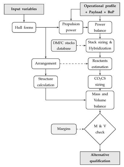
Figure 1.
Alternatives design flowchart. BoP, Balance of Plant. DMFC, Direct Methanol Fuel Cell. CO2CS, CO2 Capture System. M & V, Mass and Volume.
Table 2.
DMFC-AUV\QpDM variables and constraints. Upper section: definition of the number of bits for each variable and their variation range. Lower section: definition of the values of each constraint. Cph, central pressure hull.
Table 3.
Operational profile for a cruising speed of 2.058 m/s (4 knots). Power margin, 5%. Because both periods of the operational profile studied here are equal only the configuration of one of them is shown.
It should be noted that the characteristics of most fuel cell BoP components depend on the total power installed, that is, on the size and number of the fuel cell stacks installed, and conversely the power demand of the BoP has an impact on the selection of the size of the fuel cell stacks. This is the case concerning pumps, heat exchangers, piping, fluid separators, valves, cabling, or connectors. For the current version of this tool, the user must introduce tentative data for each component of the BoP and determine if it is suitable for the solution obtained after running the tool. Recursive runs will allow defining each component of the BoP more precisely and reduce the design margins. This is an iterative process that is appropriate for the purpose of this work.
2.1. Hull Forms
The present study is focused on torpedo-shaped vehicles (see Figure 2). This is the shape of approximately 55% of AUV models [5]. The profile definition of the bow and stern cones utilizes the curves proposed by D.F. Myring [17]. These equations describe the contour with the lowest drag coefficient given a body length to maximum diameter ratio (slenderness ratio).
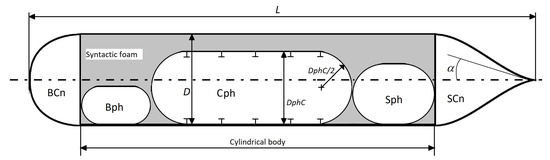
Figure 2.
AUV profile. L, total length. Lbow, bow cone length. D, outer diameter. DphC, central pressure hull diameter. , exit angle. BCn, bow cone. Bph, bow pressure hull. Cph, central pressure hull. Sph, stern pressure hull. SCn, stern cone.
The variables that define the hull forms are total length, L; length to diameter ratio, L/; length of the bow cone to total length ratio, Lbow/L; length of the stern cone to total length ratio, Lstern/L; length of the cylindrical body, Lcc; exit angle at the stern cone, ; and nose flattening index, n. Figure 2 shows the layout of the hull form of the vehicles under study.
As indicated above, this work uses the AUV models Hugin 1000, Hugin 3000, and Hugin 4500 for purposes of comparison. As a consequence, the variables that define the hull forms are the same as those of the model AUVs. This fact is reflected in Table 2, where the hull form variables adopt fixed values, and they are treated as constraints.
2.2. Propulsion Power
The propulsion power, , is calculated as follows,
where R represents the drag of the vehicle; v its speed; and stands for the efficiency of the propulsion chain, that is, the combined efficiency of the electric motor, shaft, and propeller.
R is calculated by Equation (2) [18]:
where is the density of sea water, S represents the wetted surface of the hull, and Cd stands for the drag coefficient of the vehicle.
The calculation of an accurate value of Cd is a complex problem that depends on many factors as the shape and size of the hull, control surfaces, domes, discontinuities in the hull, or the interactions between the hull and the appendages, among others. There are research works that seek to address this matter by using of computational fluid dynamics (CFD) techniques, supplemented with empirical experiments involving towing tanks [16,18,19]. In this work, a simplified approach has been used where the drag coefficient of the bare hull is increased by means of a margin coefficient that covers the effect of the appendages and other irregularities of the hull, CdMrg. The value of CdMrg was set at 0.60 following the analysis of the drag generated by a torpedo-shaped AUV carried out by the Underwater Systems Lab National Oceanography Centre of Southampton, England [20]. That work observed an increase of 57% in the value of the drag coefficient for a torpedo-shaped AUV when comparing the bare-hull values with the final vehicle. As a security margin, this percentage was rounded up to 60% for this work.
where CdMrg is the margin coefficient applied to the calculation of Cd, CvBH is the viscous coefficient of the bare hull, and Ca represents the allowance corresponding to the roughness of the surface of the hull.
To calculate CvBH, the correlation proposed by the Massachusetts Institute of Technology [21] is used:
where CF is the friction coefficient of the AUV; stands for the diameter of the AUV; L is the total length of the AUV; CP is the prismatic coefficient of the AUV, calculated by means of Equation (5); and VAUV represents the volume enclosed by the hull of the AUV.
The calculation of Ca is made in accordance with the ITTC recommended procedure 7.5-02-03-01.4 for performance prediction [22],
where ks is the roughness of the surface and Re stands for the Reynolds number of the AUV considering L as the characteristic dimension. For this work, as no data on the roughness are available, the value recommended by ITTC in the cited procedure is used: 150 µm.
Finally, to estimate CF, the correlation line ITTC1957, proposed by the International Towing Tank Conference, was used [23].
Note that wave resistance is not computed as the vehicle is considered to travel far away from the water surface.
2.3. Arrangement
Figure 2 presents a side view of the arrangement of the AUV. The hull of the AUV is divided into three main volumes: bow cone, cylindrical body, and stern cone. The bow and stern cones are both flooded volumes that contain sensor components that must be in contact with the external environment as well as other equipment, such as the propulsion electric motor or control surface actuators. The cylindrical body contains three watertight pressure hulls. The bow and the stern pressure hulls, Bph and Sph, respectively, accommodate the payload along with the necessary support equipment, such as DC/DC converters and backup batteries. The central pressure hull, Cph, contains the power plant, reactants, products, and BoP. This arrangement allows the easy update or modification of the payload as the propulsion plant remains unaltered and uses standard connections among the different containers and a modular hardware architecture as noted in Sangekar et al. [24]. To generate buoyancy, the empty volume between the pressure hulls and the hull of the AUV is filled with syntactic foam.
Defining the main dimensions of the pressure hulls requires defining the maximum and minimum values of the length and diameter of the bow and stern pressure hulls and the maximum and minimum values of the relationship between the central pressure hull and the outer diameter of the AUV: LphB, LphS, DphB, DphS, and DCph2DC, respectively. The length of the central pressure is then defined by subtracting from the length of the cylindrical body, Lcc, the sum of the lengths of the bow and stern pressure hulls. This is considered an appropriate method as the equipment inside the bow and stern pressure hulls is known in advance, and therefore allows defining the dimensions of these pressure hulls with certainty. However, the volumes in the central pressure hull are calculated by DMFC-AUV\QpDM, using the available space and trying to maximize the endurance.
2.4. Pressure Hulls
The pressure hulls are watertight cylinders with hemispherical dished heads, capable of withstanding the external hydrostatic pressure (see Figure 2). In this study, the bow and stern pressure hulls are not internally reinforced with frames. This design requires thicker pressure hulls, but it offers clean spaces that facilitate equipment installation with moderate hull thicknesses due to the relatively small diameter of the cylinders. Conversely, the central pressure hull is reinforced by a framing system, made of T-section frames, allowing thinner hulls. The framing system (see Figure 3) is defined by the thickness of the pressure hull thk; the distance between frames ls, the height of the web of the frame hsw, the thickness of the web of the frame asw, the thickness of the flange of the frame hsf, and the width of the flange of the frame asf. Regarding the construction material, DMFC-AUV\QpDM allows the user to define it by means of its density ph, Young’s modulus Eph, and Poisson’s coefficient ph.
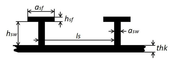
Figure 3.
Framing system. ls, frames span. hsw, web height. asw, web thickness. hsf, flange thickness. asf, flange width. thk pressure hull wall thickness
To evaluate the suitability of each pressure hull, DMFC-AUV\QpDM makes use of the specific regulations for AUVs elaborated by the American Bureau of Shipping (ABS) [25]. These regulations allow easy implementation in a mathematical model and assure the basic viability of the structure in a quick process. The ABS method defines the maximum allowable working pressure, that is, the maximum external hydrostatic pressure due to the water column above the AUV, based on different strength components and establishing additional requirements for frames construction, namely, minimum inertia and maximum slenderness ratio. In this case, and in accordance with the arrangement of the pressure hulls, the strength components evaluated are: the inter-stiffener strength, the longitudinal stress at the frame, the overall buckling strength, the stiffener stresses, the circumferential tripping stress on the stiffener, and the limit pressure for spherical shells.
2.5. Payload, BoP and Auxiliary Equipment
The payload of an AUV consists of a set of sensors and their associated equipment that provide the AUV with the capability of carrying out different missions. Their definition data is stored in a database where each device is defined by a unique identifier, its nominal power, hydrostatic pressure it can withstand, its dry weight and buoyancy, its shape and dimensions, and its position in the vehicle. There are two feasible shapes: cylindrical or parallelepiped. In the first case, the dimensions of an item are its length and diameter, and in the second case, the dimensions are its length, width, and height. There are five eligible positions: bow cone, bow pressure hull, central pressure hull, stern pressure hull, or stern cone. This configuration allows the user to configure the arrangement of the vehicle and decide on the most suitable position of the sensors, thereby avoiding interference among them.
The BoP combines all the equipment needed for the fuel cells and batteries to operate on such a manner that they form a power plant. This group includes valves, pipes, pumps, power converters, etc. The definition of these items is equivalent to the definition of payload equipment, and they are stored in the same database. Fuel cell stacks and batteries are not included in this database as they constitute the core of the power plant and are sized by DMFC-AUV\QpDM for each vehicle depending on the defined operative profile.
The auxiliary equipment consists of the remaining elements needed for the operation of the AUV, such as control surfaces actuators, an electric propulsion electric motor, communication equipment, etc. As with the payload and BoP, the characteristics of these devices are stored in the cited database.
2.6. Operational Profile and Power Plant Hybridization
DMFC-AUV\QpDM allows the user to define an operational profile in the form of a two-level cyclic power demand. Each stage is defined by a time span; a cruising speed; the utilization factors, Ku of the devices that integrate the payload; and auxiliary equipment and a power margin that covers possible uncertainties. Figure 4 shows two different operational profiles. Profile
 is characterized by a phase with a high power demand and a much longer duration than the low power demand phase. This pattern can be applied to an AUV scanning the seabed with a side-scan sonar in a rectangular scan pattern. Profile
 is the opposite, a power demand with short peaks and long standby periods. It can correspond to a surveillance AUV that takes and transmits data from the environment during short periods and remains in a standby state for the remainder of the time.
is characterized by a phase with a high power demand and a much longer duration than the low power demand phase. This pattern can be applied to an AUV scanning the seabed with a side-scan sonar in a rectangular scan pattern. Profile
is the opposite, a power demand with short peaks and long standby periods. It can correspond to a surveillance AUV that takes and transmits data from the environment during short periods and remains in a standby state for the remainder of the time.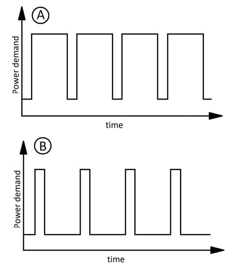
Figure 4.
Power demand patterns for two different operational profiles. , operational profile characterized by long high power demand periods and , operational profile characterized by short power peaks.
, operational profile characterized by long high power demand periods and , operational profile characterized by short power peaks.
Regular operational profiles, as the one described above, allow the hybridization of fuel cell with an auxiliary energy storage system (AESS). This allows balancing the power delivery in a proper way thereby resulting in higher global efficiencies and more compact power plants. In this case, DMFC-AUV\QpDM implements the method proposed by Cai et al. to size the fuel cell and the AESS [26]. As discussed therein, the AESS may consist of a capacitor or a pack of batteries of different types. In this case, only Li-ion batteries are considered for two reasons: First, the power peaks of the expected operational profiles are not big enough to consider capacitors. Second, this battery type is a proven technology that allows higher energy densities and specific energies than other commercial battery types [27].
In regard to Figure 4, the prominence of the fuel cell over the battery in a hybridized power plant will be more significant in profile
than in profile
in terms of delivered power. In both cases, the hybridization will be sized in such a way that during low power consumption the fuel cell recharges the batteries and, at the same time, the fuel cell operates near the desired working point. In this paper, this working point is that which is close to the maximum efficiency. For a given power output, this decision results in larger and heavier stacks. However, in this case, the influence on the design of the volume and mass of the reactants and products is higher than those of the fuel cell. Thus, the result is more compact global designs for a given endurance.
than in profile
in terms of delivered power. In both cases, the hybridization will be sized in such a way that during low power consumption the fuel cell recharges the batteries and, at the same time, the fuel cell operates near the desired working point. In this paper, this working point is that which is close to the maximum efficiency. For a given power output, this decision results in larger and heavier stacks. However, in this case, the influence on the design of the volume and mass of the reactants and products is higher than those of the fuel cell. Thus, the result is more compact global designs for a given endurance.2.7. Power Plant
Figure 5 shows a sketch of the power plant studied herein. The core of the power plant consists of a DMFC stack  connected in parallel to a set of Li-Ion batteries
  , thereby forming a hybridized system. This hybrid system is connected to a power bus
  that distributes the electrical power to the consumers. To refrigerate the power plant, the sea
  is used as a heat sink. The stack cooling loop consists of an open heat exchanger located outside the AUV
  , a cooling pump
  , and a reservoir that is also used also as an expansion vessel
  . The methanol is stored in its pure state in a specific tank
  that is equipped with a pressure equalization valve to avoid undesired vacuum effects due to emptying the tank. In the case of an emergency or shut down, this tank is automatically isolated by a normally-closed solenoid valve
  . The concentration of methanol in the anode circuit is maintained at the desired value, cMeOH, by a concentration sensor
  that is installed inside a methanol reservoir
  , which acts also as gas separator. This sensor controls the methanol feeding pump
  . The anode flow is impelled by a pump
  placed at the inlet of the anode to avoid cavitation due to the presence of CO2 bubbles. The CO2 that leaves the reservoir is impelled by a a blower
  through the CO2 Capture System (CO2CO)
  where it is captured by the adsorbent material. The excess stream is led to a heat exchanger
  where the heat produced inside the CO2CS is evacuated. After cooling, this stream is blended with the CO2 stream coming from the reservoir and recirculated through the CO2CS. This loop allows both refrigerating the CO2CS and reducing the temperature of the stream coming from the reservoir, thereby favouring the CO2 capture. A cooling loop consisting of an open heat exchanger located outside the AUV
  , a cooling pump
  , and a reservoir
  evacuates the heat of the CO2CS to the sea. Regarding the oxygen reduced at the cathode of the fuel cell, it is stored as compressed pure oxygen at 35 MPa in a cylinder
  equipped with a pressure reduction valve that lowers the pressure to 2 MPa
  . The reason for using compressed oxygen is its simplicity. The use of pure oxygen rather than air leads to a more compact oxygen storage system for the same endurance. The oxygen is released by a low flow electronic pressure regulator
  that reduces the O2 pressure to 100 kPa. This O2 enters into a loop connected to the cathode where a blower
  keeps the stream circulating. The water produced in the cathode and the excess of oxygen are directed to a gas separator
  similar to the CO2 separator in the anode loop . The excess oxygen is led to the blower and recirculated to the fuel cell. The water produced is distributed by means of a dedicated pump
  and a set of four 3-way valves
  to the anode loop or to the water storing tanks
  that form the trimming system. These tanks are located at the ends of the central pressure hull, thereby maximizing the righting momentum. This configuration allows both managing the trim of the AUV and refilling the anode circuit with just a single conventional pump. The anode gas separator also acts as a solution reservoir allowing an intermittent refilling of water from the cathode and, in this way, the operation of the trim control system. Finally, the installation is managed by the corresponding electronic control and management system
  . This system implements a control algorithm to manage the power plant. In this sense, works as those published by Karaoglan et al. [28] and Wilhelm et al. [29] can be used.
connected in parallel to a set of Li-Ion batteries , thereby forming a hybridized system. This hybrid system is connected to a power bus that distributes the electrical power to the consumers. To refrigerate the power plant, the sea is used as a heat sink. The stack cooling loop consists of an open heat exchanger located outside the AUV , a cooling pump , and a reservoir that is also used also as an expansion vessel . The methanol is stored in its pure state in a specific tank that is equipped with a pressure equalization valve to avoid undesired vacuum effects due to emptying the tank. In the case of an emergency or shut down, this tank is automatically isolated by a normally-closed solenoid valve . The concentration of methanol in the anode circuit is maintained at the desired value, cMeOH, by a concentration sensor that is installed inside a methanol reservoir , which acts also as gas separator. This sensor controls the methanol feeding pump . The anode flow is impelled by a pump placed at the inlet of the anode to avoid cavitation due to the presence of CO2 bubbles. The CO2 that leaves the reservoir is impelled by a a blower through the CO2 Capture System (CO2CO) where it is captured by the adsorbent material. The excess stream is led to a heat exchanger where the heat produced inside the CO2CS is evacuated. After cooling, this stream is blended with the CO2 stream coming from the reservoir and recirculated through the CO2CS. This loop allows both refrigerating the CO2CS and reducing the temperature of the stream coming from the reservoir, thereby favouring the CO2 capture. A cooling loop consisting of an open heat exchanger located outside the AUV , a cooling pump , and a reservoir evacuates the heat of the CO2CS to the sea. Regarding the oxygen reduced at the cathode of the fuel cell, it is stored as compressed pure oxygen at 35 MPa in a cylinder equipped with a pressure reduction valve that lowers the pressure to 2 MPa . The reason for using compressed oxygen is its simplicity. The use of pure oxygen rather than air leads to a more compact oxygen storage system for the same endurance. The oxygen is released by a low flow electronic pressure regulator that reduces the O2 pressure to 100 kPa. This O2 enters into a loop connected to the cathode where a blower keeps the stream circulating. The water produced in the cathode and the excess of oxygen are directed to a gas separator similar to the CO2 separator in the anode loop . The excess oxygen is led to the blower and recirculated to the fuel cell. The water produced is distributed by means of a dedicated pump and a set of four 3-way valves to the anode loop or to the water storing tanks that form the trimming system. These tanks are located at the ends of the central pressure hull, thereby maximizing the righting momentum. This configuration allows both managing the trim of the AUV and refilling the anode circuit with just a single conventional pump. The anode gas separator also acts as a solution reservoir allowing an intermittent refilling of water from the cathode and, in this way, the operation of the trim control system. Finally, the installation is managed by the corresponding electronic control and management system . This system implements a control algorithm to manage the power plant. In this sense, works as those published by Karaoglan et al. [28] and Wilhelm et al. [29] can be used.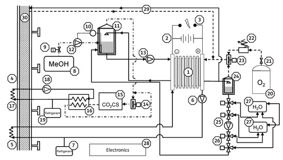
Figure 5.
Sketch of the power plant. Fuel cell stack. Batteries. Power bus. Sea water. Stack cooling heat exchanger. Stack cooling pump. Stack cooling loop. Coolant reservoir. MeOH tank. MeOH tank isolation valve. MeOH concentration sensor. MeOH reservoir and CO2 separation tank. MeOH feeding pump. Anode circulation pump. CO2CS circulation blower. CO2 Capture System (CO2CS). CO2CS heat exchanger. CO2CS cooling heat exchanger. CO2CS cooling pump. CO2CS cooling loop. Coolant reservoir. O2 cylinder. O2 pressure reduction valve. O2 low flow electronic pressure regulator. Cathode circulation blower. Cathode separation tank. Multipurpose pump. Anode refilling pump and trimming system pump. 3-way valves. Trimming tanks (bow and stern). Electronic control and management system.  Purge circuit.
  Syntactic foam.
Fuel cell stack. Batteries. Power bus. Sea water. Stack cooling heat exchanger. Stack cooling pump. Stack cooling loop. Coolant reservoir. MeOH tank. MeOH tank isolation valve. MeOH concentration sensor. MeOH reservoir and CO2 separation tank. MeOH feeding pump. Anode circulation pump. CO2CS circulation blower. CO2 Capture System (CO2CS). CO2CS heat exchanger. CO2CS cooling heat exchanger. CO2CS cooling pump. CO2CS cooling loop. Coolant reservoir. O2 cylinder. O2 pressure reduction valve. O2 low flow electronic pressure regulator. Cathode circulation blower. Cathode separation tank. Multipurpose pump. Anode refilling pump and trimming system pump. 3-way valves. Trimming tanks (bow and stern). Electronic control and management system. Purge circuit. Syntactic foam.
The use of pure O2 involves a faster degradation of the fuel cell stack. To reduce this effect, some strategies can be followed during the operation, such as increasing the oxygen flow rate briefly to eliminate possible water excess or including oxygen break periods [30,31]. When the AUV is recovered, the purge and inertization of the cathode circuit with N2 must be carried out. Accordingly, the cathode circuit is equipped with a purge circuit .
.The gas separators and consist of a partially-filled vertical cylinder as in the work of Dohle et al. [32]. The mixed stream enters into the separator through a downward pointing tube in the upper part, which facilitates the separation of two phases: gas and liquid. The liquid phase is drained by the lower part of the cylinder. The gaseous phase proceeds upwards. In the upper part of the cylinder, a hydrophobic membrane separates the CO2 or O2 from the gaseous water that condenses and falls downward. Finally, the clean gas leaves the separator through an upper exhaust.
and consist of a partially-filled vertical cylinder as in the work of Dohle et al. [32]. The mixed stream enters into the separator through a downward pointing tube in the upper part, which facilitates the separation of two phases: gas and liquid. The liquid phase is drained by the lower part of the cylinder. The gaseous phase proceeds upwards. In the upper part of the cylinder, a hydrophobic membrane separates the CO2 or O2 from the gaseous water that condenses and falls downward. Finally, the clean gas leaves the separator through an upper exhaust.2.8. Fuel Cell Stack Sizing and Consumables Calculation
As explained in Section 2.6, the nominal power, delivered by the fuel cell and batteries, is calculated according to the method proposed by Cai et al. [26]. The power demand for each phase of the operational profile is calculated by adding the propulsion power, Ẇprop, to the power demand of the equipment onboard, ẆEQ.
where ẆEQ is equal to the sum of the power of each device multiplied by its utilization factor, KU.
To size the fuel cell, DMFC-AUV\QpDM makes use of a database of DMFC stacks. This database has been created by using the software developed by the research group PICOHIMA from the Universidad Politécnica de Madrid Aero-Marine DMFC Designer® [33]. This tool allows designing DMFC stacks based on a polarization curve and a series of parameters and restrictions with special emphasis on saving weight, volume, and/or fuel, depending on the design criteria. In this case, the tool has been configured to design stacks with the highest efficiency. This leads to larger and heavier stack designs, but in the AUVs studied herein the impact of the loaded fuel, oxygen, and products on the weight and volume of the vehicle is greater than that of the installed fuel cells. Thus, to reduce the global weight and volume it is advisable to use high efficiency stacks. After calculating the power to be delivered by the fuel cells, DMFC-AUV\QpDM searches the database for a whole number of stacks that can meet the demand and selects the highest efficiency solution. The solution can be comprised of one or more stacks based on the concept of the Multi-Stack Fuel Cell [34]. In the last case, the stacks are identical in order to avoid incompatibilities, and the tool allows defining the maximum number of stacks that can be used,maxNStacks. For this work, the maximum number of stacks was limited to two units connected as shown in Figure 6. The polarization curve used is that published by Seo et al. of a DMFC stack using pure oxygen, a working temperature equal to 353.15 K (80 C), a methanol concentration equal to 1 M, and a working pressure equal to 0.1 MPa [35].
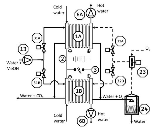
Figure 6.
Connection schema for two fuel cell stacks.  Fuel cell stack A.
  Fuel cell stack B. Batteries. Power bus.
  Stack cooling pump stack A.
  Stack cooling pump stack B. Anode circulation pump. Cathode circulation blower. Cathode separation tank.
  Anode inlet control valve stack A.
  Anode inlet control valve stack B.
  Cathode inlet control valve stack A.
  Cathode inlet control valve stack B.
Fuel cell stack A. Fuel cell stack B. Batteries. Power bus. Stack cooling pump stack A. Stack cooling pump stack B. Anode circulation pump. Cathode circulation blower. Cathode separation tank. Anode inlet control valve stack A. Anode inlet control valve stack B. Cathode inlet control valve stack A. Cathode inlet control valve stack B.
Aero-Marine DMFC Designer® calculates the methanol and oxygen consumption rates of the stack at the indicated working point, ṁMeOH and ṁO2, respectively. Once the stack has been selected and using the value of the endurance and the density of methanol and compressed oxygen, CH3OH and O2, respectively, the mass and volume of the embarked methanol and oxygen are calculated, mCH3OH and mO2, respectively. It must be noted that the endurance is used as an input rather than an output. This may appear confusing, but, in the end, it is equivalent to the definition of the capacity of methanol of the AUV and allows a more intuitive configuration of DMFC-AUV\QpDM.
The mass and volume of CO2 and water produced, mCO2, VCO2, mH2O, and VH2O, respectively, are calculated in accordance with the reactions that occur in a DMFC, i.e., 1 mol of CO2 and 2 mol of H2O for each mole of methanol [14].
2.9. CO2 Capture System
The use of a DMFC involves the production of CO2, which must be treated. An intuitive solution would be its ejection to the outside, but this method has serious drawbacks. First, it is not energy-free, as CO2 must be compressed in order to be ejected. The compressor needed for great depths would be necessarily heavy and robust. Moreover, this method lacks the necessary stealth for some missions due to the presence of bubbles and the noise produced during the ejection process. Some works study the feasibility of ejecting the CO2 while minimizing the energy consumption [36,37,38], but they have not been considered here because of their complexity, in addition to the previously mentioned difficulties.
In this work, a Carbon dioxide Capture System (CO2CS), which uses a physical adsorbent material, is considered. Physical adsorbents make use of van der Waals forces to retain the molecules of a flow stream [39]. The adsorption process is a quiet mechanism making the CO2CS proposed very suitable for its use in AUVs. A blower circulates the CO2 produced through the adsorbent material where it is captured. Adsorption is an exothermic process and the generated heat must be evacuated. This effect is achieved by the excess stream that passes through a heat exchanger where it is cooled. It is subsequently blended with the CO2 stream coming from the anode gas separator and redirected to the CO2CS again. The system is easily regenerable as the captured CO2 can be released by heating and increasing the pressure. The calculations were carried out using two different materials: Zeolite 13X and Mg-MOF-74. Zeolites are microporous aluminosilicate minerals, characterized by their wide contact surface combined with high porosity and high thermal stability. Among all the zeolites, Zeolite 13X was chosen as it presents the highest adsorption capacity for CO2 [40]. Mg-MOF-74 is a Metal–Organic Framework material (MOF) that combines an organic structure (framework) with active nodes consisting of metal ions. This MOF presents the highest capture capacity for CO2 in accordance with the work of Liu et al. [41] but, unlike Zeolite 13X, it is more expensive and its higher affinity to water makes necessary an excellent device for separating the CO2 produced by the fuel cell from the aqueous stream transporting it [42].
To calculate the amount of adsorbent needed, mads, DMFC-AUV\QpDM makes use of the adsorption isotherm curves published by Bao et al. [43]. These curves indicate the capture capacity of a material under certain conditions of pressure, pads, and temperature, Tads. In the case of the adsorption of CO2 by Zeolite 13X or Mg-MOF-74 the uptake capacity decreases as temperature increases. In the worst scenario, Tads was taken equal to 318 K as this is the higher temperature of the isotherms available. The capture capacity of Mg-MOF-74 is 2.4 times greater than the capacity of Zeolite 13X at 318 K (45 °C) and 100 kPa, 8 molCO2/gMOF versus 3.25 molCO2/gZeolite. However, the density of Mg-MOF-74 is also higher: 0.909 kg/m3 [44] versus 0.689 kg/m3 [45].
To facilitate the circulation of the CO2 and allow its uniform distribution inside the CO2CO, the absorbents are used in a bead format with a diameter equal to 2.5 mm. This involves a maximum packing density equal to 74.048 % in accordance with the Kepler conjecture [46].
2.10. Mass and Volume Balances
Once the needed data have been collected, DMFC-AUV\QpDM verifies if the solution proposed is feasible from the point of view of volume and mass. On the one hand, the internal net volume of each space must be larger than the summation of the volume of the equipment allocated inside. On the other hand, the total mass of the AUV must be smaller than its displacement, . This verification stage should not be confused with the quality of the solution that is established by the genetic algorithm that seeks and selects the best solution. If a design does not pass this test it is rejected.
In order to take into account the uncertainties and lack of definition of the design, DMFC-AUV\QpDM allows defining a volume design margin for the central pressure hull as a percentage of the total net volume of this pressure hull and a mass design margin as a percentage of the total mass: MrgVol0 and MrgMass0, respectively. The volume design margin only affects the central pressure hull because the definition of the geometry and volumes located in this space performed by DMFC-AUV\QpDM and they cannot be determined prior to running the tool, as the definition of the bow and stern pressure hulls can be studied in advance by the designer, as explained in Section 2.3.
Regarding the mass margin, ideally a refined design would have a mass margin equal to 0. In the case that this margin is positive, it can be offset by adding a ballast like lead bricks.
2.11. The Genetic Algorithm
In the genetic algorithm (GA) used here, one single individual is defined by the values of the 13 variables and 8 constraints listed in Table 2. They are collected in a population matrix, A, where each column represents one individual [33]. These values are coded as binary numbers to facilitate the calculation process. DMFC-AUV\QpDM allows establishing the upper and lower limits of each variable and the number of bits that defines it, i.e., its resolution. The larger the number of bits of a variable, the more precisely it can be defined and the more values that can be evaluated. However, the calculation time soars and the convergence to a solution is more difficult.
The goal of the GA is to find a configuration that maximizes or minimizes a merit function (MF). A merit function, also known as a figure-of-merit function, is a function that measures the agreement between data and the fitting model for a particular choice of the parameters [47]. The solution that provides the best result is considered the best solution. In this case, the MF is equal to the endurance of the vehicle, e, multiplied by three binary functions that depend on the strength of the pressure hulls, the volume margin of the central pressure hull, and the mass margin of the whole AUV. The best design will be the individual that maximizes the value of the MF, that is, the AUV with the longer endurance, the pressure hulls of which can withstand the design operating depth and the arrangement of which complies with the defined volume and mass margins. The MF can be written as
where
DMFC-AUV\QpDM seeks the vehicle with the higher endurance and discards the designs whose pressure hulls are not suitable for the design navigation depth or do not have sufficient volume or mass margin.
The GA is characterized by three parameters, the population size, N, the number of generations, ngens, and the mutation rate, r [33]. These parameters must be carefully adjusted to allow the GA to find solutions efficiently. In this regard, N must be sufficiently large to assure a proper population diversity, but large values will lead to long calculation times and a high use of memory. A small value of ngens saves calculation time, but a small value will make it difficult for the GA to achieve the best result due to the lack of evolution of the population. Finally, a correct value of r will prevent convergence to local solutions, but the opposite is the impossibility of the GA to converge.
Figure 7 depicts how the GA achieves the solution. First of all, the initial population matrix, A, is randomly set defining N individuals whose variable values are coded in binary format. Next, these values are decoded into real numbers, and each design is evaluated in accordance with the aforementioned algorithm (see Figure 1) and MF. The subsequent step is the crossover of the individuals, that is, the random exchange of genes between two individuals to produce a new individual (offspring). To select which individual will be crossed with another, their merit values are arranged in a toroidal matrix M and the merit values of the neighbors, immediately above, below, on the left and on the right, are compared to each other. The selected candidate will be the individual with the highest value. The new individuals are stored in a new population matrix B. To maintain the diversity of the population, once the crossover stage is complete, r% of the genes of the population B are randomly changed, and the merit matrix of this population is calculated. Finally, both populations A and B are compared through their merit values, and the individuals of the initial population A with a lower merit than their offspring’s of the population B are replaced by the latter, thereby producing the next generation. After ngens generations, the individual with the highest merit value is selected as the problem solution.
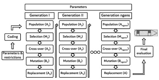
Figure 7.
GA loop.
Following the same approach as in the work of Santiago et al. [33], the tool is run 20 times for each case to check if the solution is a global optimum of the search space. In this way, possible local optimums can be detected and discarded.
2.12. Parameters of the Genetic Algorithm
The solution of the optimization problem by the GA is performed in an environment characterized by a set of 34 parameters that define the boundary conditions. This list includes all the necessary data to carry out the required calculations such as the maximum operating depth, depth, the water density, , or the roughness of the hull surface, ks. In contrast to the variables, the value of parameters is fixed and do not change during calculations. Table 4 lists all the parameters of DMFC-AUV\QpDM.
Table 4.
Input parameters of the genetic algorithm (GA). PH, pressure hull.
3. Problem Configuration
As stated in the Introduction, the methodology followed in this work involves the comparison between the reference model and its theoretical equivalent. Two AUVs are deemed to be equivalent if they have the same characteristics insofar as sensors, cruising speed, maximum navigation depth, and size. This principle includes restrictions in the configuration of DMFC-AUV\QpDM which are described below.
3.1. Hull Forms and Pressure Hulls Arrangement
For the purpose of this work, the length, L, and the relationship of length to external hull diameter, L2D, of the AUV designs produced by DMFC-AUV\QpDM are the same as those of the reference AUVs. Likewise, a value equal to 2.5 was assigned to the n index, thereby producing a parabolic profile similar to the bow of the reference models, and the value of the stern escape angle was set to 8, thereby coinciding with the escape angle of the reference AUVs.
Regarding the pressure hulls, the dimensions of the bow and stern pressure hulls were made fixed based on the dimensions of the equipment located therein. Only the thickness value of these two pressure hulls is allowed to vary and is assigned by DMFC-AUV\QpDM.
3.2. Payload, Auxiliary Equipment and BoP
To define the three basic attributes of the on-board devices, namely, mass, volume, and power demand, needed by DMFC-AUV\QpDM, data from commercially available equipment was used whenever possible. This method has the advantage of being simple while working with actual data, which reduces the uncertainty of the design. This is the case of pumps, valves, blowers, or sensors. For equipment that is not commercially available or in case the data of which was not accessible, reasonable assumptions were made to define their attributes. This is applicable mainly to gas separators and heat exchangers.
The characteristics of all the elements on-board the AUVs are included in Appendix A. Payload is described in Table A1, and these data are the same for the three designs under study. The same is applicable to Table A2 which contains the characteristics of the auxiliary equipment. Finally, the BoP is included in Table A3 for Model 1000 and Table A4 for Model 3000 and Model 4500.
The definition of payload and auxiliary equipment is based on the capabilities of the reference AUVs and does not depend on the AUV size or navigation speed. However, this is not the case of BoP components whose definition needs of an iterative process because the size of the power plant is not known in advance and depends on the operational profile of the vehicle. Starting from the power plant schema (Figure 5 and Figure 6), the mass and heat flows and the pressure drops of the different circuits are estimated. Then, the components of the BoP are selected from commercial catalogs and incorporated to the design. As these components modify the operational profile, the design tool must be run again to check if the proposed design is coherent.
For the size estimation of cooling components, the following common assumptions were made. The cooling fluid is pure water. Sea water temperature is taken equal to 333 K to consider navigation in shallow tropical waters. This value is considered constant in spite of sea water temperature drops with depth. This allows to consider the worse conditions from the point of view of heat balance and size of the heat exchangers. The size of heat exchangers is estimated using the effectiveness-NTU method [56]. External heat exchangers are modeled similarly to counter current shell and pipe heat exchangers and CO2CS heat exchanger is modeled similarly to a plate heat exchanger.
Regarding the cooling of stacks, the following assumptions apply. The components of the cooling loop of the stacks must satisfy the needs of the fuel cell stacks running at their nominal power, although this operating regimen is never reached in accordance with the operational profile of the AUV. Temperature variation of cooling water is equal to 10 K to avoid thermal tensions inside the stack. The heat flow to evacuate is equal to the energy of the methanol flow calculated through its Lower Heating Value minus the nominal power of the fuel cell.
The heat produced by the CO2CS is calculated from the values of the isosteric heat of adsorption reported by Bao et al. [43]. The CO2 flow that exits the CO2CS is equal to twice the production rate of CO2.
The power consumption of pumps and blowers is considered fixed and equal to their nominal power although the real demand is lower. In the case of O2 and CO2 blowers, and , respectively, their minimum flow must be three times the O2 consumption and CO2 production rates, respectively.
and , respectively, their minimum flow must be three times the O2 consumption and CO2 production rates, respectively.For liquid and low-pressure gas pipes, nitrile butadiene rubber flexible pipes with an outer diameter equal to 7 mm were considered. This material shows good resistance to hydrocarbons, is light and flexible and can be used with fluid temperatures up to 373 K [57]. The connection between the O2 pressure reduction valve and the O2 low flow electronic pressure regulator is made by a 1/16” stainless steel pipe (see Figure 5). To estimate the length of the power plant piping “a half central pressure hull length” was assigned to each pipe branch. Finally, the mass of the liquid fluids inside pipes was included in the calculation.
and the O2 low flow electronic pressure regulator is made by a 1/16” stainless steel pipe (see Figure 5). To estimate the length of the power plant piping “a half central pressure hull length” was assigned to each pipe branch. Finally, the mass of the liquid fluids inside pipes was included in the calculation.Gas separators are cylinders with a total mass equal to 5 kg and a height equal to one half the central pressure hull diameter. Refrigerator reservoirs are considered 80 mm side cubes made of PVC and filled with 250 mL of water.
In general, the assumptions adopted to estimate the size and power of BoP elements lead to an oversized BoP. However, they produce confident designs with a limited effort enough to reach conclusions on the use of DMFCs to power AUVs.
3.3. Operational Profile
Table 3 shows the definition of the operational profile. As in the reference AUVs, the payload and operational profile of the three models is the same. Because the information published by the manufacturer of the reference vehicles corresponds to a steady power demand, the same principle has been applied to this work. This results in the absence of batteries hybridized with the fuel cells. In any case, a small auxiliary battery is included in each pressure hull. These auxiliary batteries feed critical equipment, such as the Iridium connection during emergencies, enable a stand-by condition thereby feeding sensors and communication equipment if the power plant is off for a short time, and are used to start-up and shut-down the power plant.
3.4. Input Values
Table 2 and Table 4 show variables and parameters values that define the problem to be solved by the DMFC-AUV\QpDM. The variables related to the main dimensions of the vehicles are fixed as they must be the same as those of the reference AUVs. As a consequence, the number of bits of these variables is equal to one, and their possible maximum and minimum values are the same and equal to that of the reference model. Regarding the number of bits of each non-fixed variable, they were assigned in order to get a resolution around one millimeter for variables related to thicknesses and frames and 4 mm for central pressure hull diameter. Finally, the configuration is the same for the three models, thereby providing DMFC-AUV\QpDM with a wide range in order to find the best solution.
3.5. Genetic Algorithm
GA has been configured with a population size, N, equal to 1600 individuals, 1600 generations, ngens, and a mutation rate, r, equal to 8%.
4. Results and Discussion
Table 5 contains the characteristics of the designs obtained with DMFC-AUV\QpDM for the Model 1000, the Model 3000, and the Model 4500, respectively, and Figure 8 shows the corresponding sketches of such designs. These results are achieved after running the tool 20 times for each case, obtaining the same optimum value of the merit function (MF) 18 out of 20 times as a minimum, so it can be considered that the results given by DMFC-AUV\QpDM are robust enough.
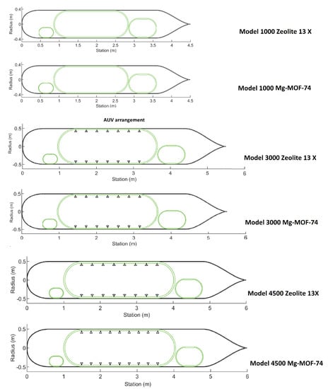
Figure 8.
Sketches of the resulting Model 1000, Model 3000, and Model 4500 equipped with CO2CSs based on Zeolite 13X and Mg-MOF-74.
When using Zeolite 13X as a CO2 capture agent, only the Model 1000 presents an autonomy greater than that of the reference vehicle, 29.6 h versus 24 h, that is an increment equal to 23.3%. In the case of the Model 3000, it is observed a decrease equal to 10.5% in the value of the estimated endurance, 53.7 h versus 60 h. For the Model 4500 this decrease is reduced to 3.3%, that is, 58 h versus 60 h from the reference model.
In the case of Mg-MOF-74, the results are quite different. The estimated endurance values are larger that those of the reference AUVs for the three models. As in the case of Zeolite 13X, the expected endurance increases with the size of the vehicle. This effect is more influenced by changes in the diameter of the vehicle than by changes in its length. This can be explained by the cylinder volume formula, , where the diameter is an order 2 magnitude while the cylinder length is an order 1 magnitude. Model 1000, using Mg-MOF-74, offers an endurance value 141.3% larger than that of the reference AUV, 57.9 h versus 24 h, while Model 3000 and Model 4500 increase their original endurance by 73.3 % and 88.0 %, respectively, 60 h versus 104.0 h in the first case and 60 h versus 112.8 h in the last case. The different endurance increment rate observed between Model 1000 and Model 3000 and Model 4500 could be attributed to the use of Al/HP semi-fuel cells. HUGIN 3000 and HUGIN 4500 use Al/HP semi-fuel cells that have a larger energy content than Li-Polymer batteries which are used by HUGIN 1000 [6,58].
In all cases, the diameter of the central pressure hull is the maximum possible, that is, the outer diameter minus two times the thickness of the external hull. This was expected as it maximizes the volume of the central pressure hull thereby allowing to load larger amounts of fuel, O2 and CO2 adsorbent.
Regarding the structure, colored in dark green in Figure 8, thicknesses increase with design navigation depth as expected, but it is observed that the designs for the same depth are not equal, as might be expected. This is not surprising as MF does not penalize any design by the arrangement of its central pressure hull but by the maximum external pressure they can withstand. In other words, two different structural arrangements, suitable for the same design navigation depth, are equal for DMFC-AUV\QpDM. Anyway, this behavior does not influence the conclusions of this work since it does not impact the endurance results. If some arrangements were preferable to others, MF could be modified to prioritize them.
The power demand of the payload and auxiliary equipment, 274.9 W and 52.6 W, respectively, is equal in all the cases as the installed sensors and the operation profile are the same. BoP power is lower for Model 1000 than for Model 3000 and Model 4500 where this value is the same. Once again, these results were expected as the power plant of Model 1000 is made of a single 1000 W fuel cell stack while the power plant of Model 3000 and Model 4500 contains two 700 W stacks. Despite the fact that heat and mass flows are greater, a two-stack power plant (Figure 6) involves the use of two cooling pumps and two normally-closed control valves rather than one cooling pump and no control valves used in a single-stack power plant.
When comparing the volume claimed by the fuel cell stacks and the corresponding BoP with the the volume claimed by methanol, O2 storage system, CO2CS, and water tanks, the first is, on average, 3.5% of the second; that is, most of the volume of the central pressure hull is dedicated to fuel, O2 and by-products storage. More in detail, it is observed that the design of the power plant is highly influenced by the CO2CS. If Zeolite 13X is used as adsorbent material, the volume dedicated to the CO2CS is 52% on average of the volume of the central pressure hull in all the cases. This aspect can be improved by using Mg-MOF-74 that occupies 32% of the net volume of the central pressure hull, leading to more compact CO2CS along with longer values of endurance.
Regarding the total dry mass, the AUVs outlined are heavier than the reference AUVs for the same dimensions (see Table 1); specifically, when using Zeolite 13X as CO2 capture agent, the Model 1000 is around 1.30 times heavier than its reference AUV, Model 3000 1.63 times and Model 4500 1.54 times. If Mg-MOF-74 is used, these figures are bigger: 1.37 for Model 1000, 1.72 for Model 3000, and 1.62 for Model 4500. The weight of the adsorbent is on average 15% of the total weight of the AUV when Zeolite 13X is used and this rate is reduced to 11% when using Mg-MOF-74. This reduction is explained by the higher CO2 capture capacity of Mg-MOF-74 compared to that of Zeolite 13 X, 2.46 times higher under the same pressure and temperature conditions, see Table 4. Although it is difficult to explain why DMFC AUVs are heavier than the reference models without a detailed knowledge of the construction of the last ones, a short analysis is done. On the one hand, and considering the values of specific energy of Al/HP semi-fuel cells, see Table 6, the theoretical weight of an Al/HP semi-fuel cell, with an efficiency equal to 1, and an energy content equal to that of Model 3000 using Zeolite 13X and Model 3000 using Mg-MOF-74, would be equal to 725.3 kg and 1404.7 kg, respectively. In the case of Model 4500, those figures would be, 783.6 kg and 1536.9 kg, respectively. Therefore, an AUV powered with Al/HP semi-fuel cells would be heavier for the same amount of energy. On the other hand, the payload is similar and not big weight deviations are expected. An explanation for this divergence can be found taking into account the presence of the central pressure hull that represents from 34.4% of the total dry mass in the case of the Model 1000 with Mg-MOF-74 to 48.4% in the case of the model 4500 using Zeolite 13X. Reference AUVs use pressure tolerant batteries and semi-fuel cells allowing a mass saving. This weight increment makes necessary the use of syntactic foam filling void spaces to get the hydrostatic equilibrium, but this foam adds an extra weight to the final balance contributing to the weight increment observed.
Table 6.
Energy stored by the DMFC-AUV. LHV of methanol from [14]. Reference AUV energy data from [6,58]
In all the cases, the results obtained demonstrate that the volume and weight margins defined are respected, sufficient space for the installation of the equipment and addressing the deviations due to the uncertainties of the design process. It must be noted that for all the designs, the value of the volume margin is the lowest possible while the mass margin remains far above the minimum value. This means that the power plant proposed is essentially bulky rather than heavy and this trend is stronger as the AUV is smaller.
In terms of energy stored, Table 6 sets forth the energy density and specific energy of the different designs taking the net volume of the central pressure hull and the mass of the components of the power plant, i.e., fuel cell stacks, BoP, consumables, and products inside, as well as the defined volume margin. The figures of this table are in line with the aforementioned results, considering that energy content is equivalent to endurance. On the one hand, if Zeolite 13X is used, the energy density and specific energy of a DMFC power plant is much lower than the same power plant using Mg-MOF-74. On the other hand, the size of an AUV has a great impact on the applicability of DMFC-based power plants to power AUVs. Larger AUVs are more likely to favour the installation of this type of power plant. Finally, Mg-MOF-74 provides endurance values approximately 40% longer than those provided by batteries.
Table 6 also shows the energy density and specific energy of the reference AUVs for Model 3000 and Model 4500, that is, the figures for the Al/HP semi-fuel cell. From a comparison analysis, it follows that a DMFC-based power plant as the one proposed here would be bulkier than an Al/HP semi-fuel cell no matter the CO2 capture agent is used. However, considering the specific energy values, it is observed that the DMFC power plant is lighter than a Al/HP semi-fuel cell when Mg-MOF-74 is used as CO2 capture agent, being almost equally heavy when Zeolite13X is used.
5. Conclusions
In terms of endurance, this work studies the advantages of powering an Autonomous Underwater Vehicle (AUV) with a power plant based on a Direct Methanol Fuel Cell (DMFC). Accordingly, a quick preliminary design modeling software that makes use of a genetic algorithm to solve a multi-objective optimization problem has been developed. This tool allows defining the payload of the vehicle using real data of the equipment to be loaded as well as the operation profile. The result is the initial design of an AUV powered by a DMFC.
As the power plant proposed generates CO2, a capture system is needed (CO2CS). For this application, the adsorption mechanism has been considered as the most appropriate method. Two different adsorbent materials have been evaluated: Mg-MOF-74 and Zeolite 13X. Mg-MOF-74 has the highest CO2 capture capacity under the same ambient conditions, but it is heavier and more expensive than Zeolite 13X is. This fact makes the selection of the adsorbent material a relevant aspect that impacts the performance of the resulting AUV.
To make the results comparable to existent AUVs, one reference AUV powered by batteries and two powered by Al/HP semi-fuel cells have been selected and used as models. The tool has been configured with the same payload, operational profile, and main dimensions of the model AUVs, and the corresponding equivalent designs have been obtained. A total of six designs have been produced, two for each reference AUV with different adsorbent materials.
The analysis of the work results concludes that the application of power plants as the one described here to power AUVs can be beneficial in terms of longer endurance values when compared to Li-Polymer batterie or semi-fuel cell powered AUVs for large AUVs.
The CO2CS has been revealed as the most critical component of the power plant because of its volume that can reach up to 52% of the total volume of the power plant. In this regard, the capture capacity of the adsorbent material is a crucial matter. It was observed that a design using Mg-MOF-74 (CO2 capture capacity at 348 K and 100 kPa equal to 8 molCO2/kgMg-MO-74) has an endurance value of approximately twice the same design using Zeolite 13X (CO2 capture capacity at 348 K and 100 kPa equal to 3.25 molCO2/kgZeolite 13X) regardless of size. If a good adsorbent, such as Mg-MOF-74, is used, endurance values 88% longer than those obtained from using Al/HP semi-fuel cells are achievable, see Model 4500 Mg-MOF-74 in Table 5. In the case of Li-Polymer batteries, this increment reaches up to 140% of the reference endurance, see Model 1000 Mg-MOF-74 in Table 5.
In view of these findings, DMFCs arise as a potential technology to power AUVs, although more detailed studies are still required. In this regard, the design software developed in this work is a good tool due to its flexibility and robustness. It is able to assess new types of carbon dioxide capture systems as well as other operational profiles, creating a complete map of applicability of DMFC in AUVs.
Author Contributions
Conceptualization, A.V.-H. and T.J.L.; methodology, A.V.-H.; software, A.V.-H. and Ó.S.; investigation, A.V.-H.; resources, L.M. and T.J.L.; writing—original draft preparation, A.V.-H.; writing—review and editing, A.V.-H., Ó.S., Loredana Magistri and T.J.L.; visualization, A.V.-H.; supervision, T.J.L.; project administration, T.J.L.; funding acquisition, T.J.L. All authors have read and agreed to the published version of the manuscript.
Funding
This research was funded by the Spanish Ministry of Science, Innovation nd Universities and European Regional Development Fund through Research Project ENE2017-86711-C3-2-R and also ENE2017-90932-REDT.
Acknowledgments
The authors gratefully acknowledge the Universidad Politécnica de Madrid, Spain, the partial funding of this work through the foundation Consejo Social.
Conflicts of Interest
The authors declare no conflict of interest. The funders had no role in the design of the study; in the collection, analyses, or interpretation of data; in the writing of the manuscript; or in the decision to publish the results.
Appendix A. Payload, Auxiliary Equipment and BoP
Table A1.
Payload characteristics. Bph, bow pressure hull. Cph, central pressure hull. Sph, stern pressure hull. Bcn, bow cone. Scn, stern cone. Hull, attached to the external hull.
Table A1.
Payload characteristics. Bph, bow pressure hull. Cph, central pressure hull. Sph, stern pressure hull. Bcn, bow cone. Scn, stern cone. Hull, attached to the external hull.
| Code | Description | Number | Location | Mass (kg) | Length (mm) | Width (mm) | Height (mm) | Diameter (mm) | Power (W) | Reference |
|---|---|---|---|---|---|---|---|---|---|---|
| SSS-PD | Side Scan Sonar Pods | 2 | Hull 1 | 2.5 | 500 | 46 | 32 | 0 | [59] | |
| SSS | Side Scan Sonar Transducers | 2 | Bph | 1.4 | 180 | 110 | 12 | [59] | ||
| SBP-T | Sub Bottom Profiler Transducer | 1 | Scn | 32.0 | 60 | 470 | 0 | [60] | ||
| SBP | Sub Bottom Profiler Electronics block | 1 | Sph | 10.0 | 400 | 250 | 150 | [60] | ||
| CAM | Still image camera | 1 | Bcn | 0.65 | 99 | 53 | 4.8 | [61] | ||
| TUR | Turbidity sensor | 1 | Bcn | 1.3 | 178 | 63 | 0.9 | [62] | ||
| MBE-P | Multi-beam Echosounder Projector | 1 | Sph | 13.4 | 480 | 109 | 196 | 0 | [63] | |
| MBE-R | Multi-beam Echosounder Receiver | 1 | Sph | 12.9 | 480 | 109 | 190 | 0 | [63] | |
| MBE | Multi-beam Echosounder Interface | 1 | Sph | 2.4 | 280 | 170 | 60 | 100 | [63] |
1 Side Scan Sonar pods attached outside the external hull, with their longitudinal axis parallel to the AUV axis, one at each side.
Table A2.
Auxiliary equipment characteristics. Bph, bow pressure hull. Cph, central pressure hull. Sph, stern pressure hull. Scn, stern cone.
Table A2.
Auxiliary equipment characteristics. Bph, bow pressure hull. Cph, central pressure hull. Sph, stern pressure hull. Scn, stern cone.
| Code | Description | Number | Location | Mass (kg) | Length (mm) | Width (mm) | Height (mm) | Diameter (mm) | Power (W) | Reference |
|---|---|---|---|---|---|---|---|---|---|---|
| Group: Navigation | ||||||||||
| IMU | Inertial Measurement Unit | 1 | Bph | 0.055 | 45 | 22 | 39 | 2 | [64] | |
| CMP | Digital Compass | 1 | Bph | 0.204 | 77 | 46 | 16 | 1 | [65] | |
| DVL/ADCP | Doppler velocity log | 1 | Sph | 2.7 | 164 | 114 | 1.3 | [66] | ||
| GNSS | Multi-GNSS receiver Chip | 1 | Bph | 0.001 | 17 | 13 | 3 | 0.3 | [67] | |
| PRS | Pressure Sensor | 1 | Bph | 1.0 | 185 | 40 | 0.4 | [68] | ||
| ALT | Altimeter | 1 | Sph | 1.5 | 230 | 50 | 1.5 | [69] | ||
| STER | Rudder servo motor | 4 | Scn | 0.24 | 81 | 33 | 1.5 | [70] | ||
| STER-G | Rudder servo gearbox | 4 | Scn | 0.156 | 51 | 30 | [71] | |||
| SVCN | Servo controller | 4 | Sph | 0.1 | 75 | 47 | 20 | 1 | [72] | |
| Group: Propulsion | ||||||||||
| PROP | Propulsion chain | 1 | Scn | 3.9 | 305 | 50 | 1 | [73] | ||
| Group:Communications | ||||||||||
| USBL | Underwater Transponder | 1 | Scn | 8.1 | 403 | 110 | 57 | [74] | ||
| WIFI | WiFi connection | 1 | Bph | 0.047 | 89 | 51 | 20 | 3.6 | [75] | |
| ETH | Gigabit Ethernet connection | 1 | Bph | 0.02 | 41 | 25 | [76] | |||
| IRID | Iridium modem | 1 | Bph | 0.17 | 100 | 64 | 16 | 12 | [77] | |
| Group: Data processing | ||||||||||
| MBO | Mother board | 3 | Bph Cph Sph | 0.281 | 102 | 102 | 50 | 10.2 | [78] | |
| HD | Hard disk | 3 | Bph Cph Sph | 0.082 | 101 | 71 | 7 | 3.5 | [79] | |
1 The propulsion chain power demand is calculated in accordance with Section 2.2.
Table A3.
BoP components characteristics for Model 1000. Bph, bow pressure hull. Cph, central pressure hull.
Table A3.
BoP components characteristics for Model 1000. Bph, bow pressure hull. Cph, central pressure hull.
| Id | Code | Description | Number | Location | Mass (kg) | Length (mm) | Width (mm) | Height (mm) | Diameter (mm) | Power (W) | Reference |
|---|---|---|---|---|---|---|---|---|---|---|---|
| BATT | Auxiliary batteries | 3 | Bph Cph Sph | 1 | 110 | 68 | 38 | [80] | ||
| DC-AC | Power inverter | 1 | Sph | 3.35 | 325 | 165 | 85 | 1 | [81] | |
| DCDC12V | DC/DC converter 24 to 12 V | 2 | Bph Cph | 0.024 | 40 | 23 | 8 | 1 | [82] | |
| DCDC3V | DC/DC converter 24 to 5 V | 2 | Bph Cph | 0.024 | 40 | 23 | 8 | 1 | [83] | |
| DCDC5V | DC/DC converter 24 to 3.3 V | 1 | Bph | 0.024 | 40 | 23 | 8 | 1 | [84] | |
| STKHEX | Stack cooling heat exchanger | 1 | Hull | 5 | ||||||
| STKCOOLPMP | Stack cooling pump | 1 | Cph | 0.34 | 127 | 89 | 100 | 48 | [85] | |
| STKCOOLRSV | Stack cooling loop. Coolant reservoir. | 1 | Cph | 0.365 2 | 80 | 80 | 80 | |||
| MEOHVLV | MeOH tank isolation valve | 1 | Cph | 0.01 | 43 | 10 | 2.5 | [86] | ||
| MCS | MeOH concentration sensor | 1 | Cph | 0.1 | 33 | 68 | 16 | 0.21 | [87] | |
| MEOHRSV | MeOH reservoir and anode separator tank | 1 | Cph | 5 | 0.375 | 180 | ||||
| MEOHPMP | Methanol feeding pump | 1 | Cph | 0.64 | 42 | 42 | 42 | 9 | [88] | |
| ANOPMP | Anode circulation pump | 1 | Cph | 0.032 | 40 | 46 | 25 | 5.8 | [89] | |
| CO2CSBLW | CO2CS circulation blower | 1 | Cph | 0.018 | 37 | 44 | 23 | 0.8 | [90] | |
| CO2CSHEX | CO2CS heat exchanger | 1 | Cph | 1.07 | 172 | 74 | 52 | [91] | ||
| CO2CSOPENHEX | CO2CS open heat exchanger | 1 | Hull | 10 | ||||||
| CO2COPMP | CO2CS cooling pump | 1 | Cph | 0.041 | 46 | 25 | 26 | 5.8 | [92] | |
| CO2CSCOOLRSV | CO2CS cooling loop. Coolant reservoir. | 1 | Cph | 0.365 2 | 80 | 80 | 80 | |||
| PRV | O2 pressure reduction valve | 1 | Cph | 0.23 | 77 | 46 | [93] | |||
| LFEPR | O2 pressure regulator | 1 | Cph | 0.454 | 49 | 32 | 111 | 11.5 | [94] | |
| CATBLW | Cathode circulation blower | 1 | Cph | 0.014 | 37 | 44 | 23 | 0.8 | [90] | |
| CATSEPTNK | Cathode separation tank | 1 | Cph | 5 | 0.375 | 180 | ||||
| H2OPMP | Water pump | 1 | Cph | 0.032 | 40 | 46 | 25 | 5.8 | [89] | |
| CAT3WVLV | 3-way valves | 4 | Cph | 0.272 | 43 | 43 | 110 | 11 | [95] | |
| - | PIPING | Nitrile piping | 1 | Cph | 0.9 | 25,000 | OD:7 ID:4 | [96] | |||
| - | FLUID | Liquid fluid in pipes | 1 | Cph | 0.10 |
1 As power consumption of inverters and current converters depends exclusively on the load they are subjected to and this load depends on the operational profile no power values are indicated here. The power consumption of these items can be found in Table 3. 2 The mass of the reservoir includes the mass of a PVC container consisting in a cube with 2 mm thick. walls.
Table A4.
BoP components characteristics for Model 3000 and Model 4500. Bph, bow pressure hull. Cph, central pressure hull. Hull, attached to the external hull. OD, outer diameter. ID, inner diameter.
Table A4.
BoP components characteristics for Model 3000 and Model 4500. Bph, bow pressure hull. Cph, central pressure hull. Hull, attached to the external hull. OD, outer diameter. ID, inner diameter.
| Id | Code | Description | Number | Location | Mass (kg) | Length (mm) | Width (mm) | Height (mm) | Diameter (mm) | Power (W) | Reference |
|---|---|---|---|---|---|---|---|---|---|---|---|
| BATT | Auxiliary batteries | 3 | Bph Cph Sph | 1 | 110 | 68 | 38 | [80] | ||
| DC-AC | Power inverter | 1 | Sph | 3.35 | 325 | 165 | 85 | 1 | [81] | |
| DCDC12V | DC/DC converter 24 to 12 V | 2 | Bph Cph | 0.024 | 40 | 23 | 8 | 1 | [82] | |
| DCDC3V | DC/DC converter 24 to 5 V | 2 | Bph Cph | 0.024 | 40 | 23 | 8 | 1 | [83] | |
| DCDC5V | DC/DC converter 24 to 3.3 V | 1 | Bph | 0.024 | 40 | 23 | 8 | 1 | [84] | |
| STKHEX | Stack cooling heat exchanger | 2 | Hull | 5 | ||||||
| STKCOOLPMP | Stack cooling pump | 2 | Cph | 0.34 | 127 | 89 | 100 | 48 | [85] | |
| STKCOOLRSV | Stack cooling loop. Coolant reservoir. | 1 | Cph | 0.365 2 | 80 | 80 | 80 | |||
| MEOHVLV | MeOH tank isolation valve | 1 | Cph | 0.01 | 43 | 10 | 2.5 | [86] | ||
| MCS | MeOH concentration sensor | 1 | Cph | 0.1 | 33 | 68 | 16 | 0.21 | [87] | |
| MEOHRSV | MeOH reservoir and anode separator tank | 1 | Cph | 5 | 500 | 160 | ||||
| MEOHPMP | Methanol feeding pump | 1 | Cph | 0.64 | 42 | 42 | 42 | 9 | [88] | |
| ANOPMP | Anode circulation pump | 1 | Cph | 0.032 | 40 | 46 | 25 | 5.8 | [89] | |
| CO2CSBLW | CO2CS circulation blower | 1 | Cph | 0.018 | 37 | 44 | 23 | 1.2 | [97] | |
| CO2CSHEX | CO2CS heat exchanger | 1 | Cph | 1.47 | 172 | 74 | 73 | [98] | ||
| CO2CSOPENHEX | CO2CS open heat exchanger | 1 | Hull | 10 | ||||||
| CO2COPMP | CO2CS cooling pump | 1 | Cph | 0.041 | 46 | 25 | 26 | 5.8 | [92] | |
| CO2CSCOOLRSV | CO2CS cooling loop. Coolant reservoir. | 1 | Cph | 0.365 2 | 80 | 80 | 80 | |||
| PRV | O2 pressure reduction valve | 1 | Cph | 0.23 | 77 | 46 | [93] | |||
| LFEPR | O2 pressure regulator | 1 | Cph | 0.454 | 49 | 32 | 111 | 11.5 | [94] | |
| CATBLW | Cathode circulation blower | 1 | Cph | 0.014 | 37 | 44 | 23 | 0.84 | [90] | |
| CATSEPTNK | Cathode separation tank | 1 | Cph | 5 | 500 | 160 | ||||
| H2OPMP | Water pump | 1 | Cph | 0.032 | 40 | 46 | 25 | 5.8 | [89] | |
| CAT3WVLV | 3-way valves | 4 | Cph | 0.272 | 43 | 43 | 110 | 11 | [95] | |
 | ANOCTRVLV | Anode inlet control valve | 2 | Cph | 0.272 | 43 | 43 | 110 | 11 | [99] | |
 | CATCTRVLV | Cathode inlet control valve | 2 | Cph | 0.272 | 43 | 43 | 110 | 11 | [99] | |
| - | PIPING | Nitrile piping | 1 | Cph | 1.4 | 38125 | OD:7 ID:4 | [96] | |||
| - | FLUID | Liquid fluid in pipes | 1 | Cph | 0.15 |
1 As power consumption of inverters and current converters depends exclusively on the load they are subjected to, and this load depends on the operational profile, no power values are indicated here. The power consumption of these items can be found in Table 3. 2 The mass of the reservoir includes the mass of a PVC container consisting in a cube with 2 mm thick. walls.
References
- European Commission. Blue Indicators Online Dashboard. 2020. Available online: https://blueindicators.ec.europa.eu/access-online-dashboard_en (accessed on 15 September 2020).
- Widditsch, H. SPURV-The First Decade. APL-UW 7215, Applied Physics Laboratory University of Washington. 1973, p. 32. Available online: https://apps.dtic.mil/dtic/tr/fulltext/u2/a050816.pdf (accessed on 27 September 2020).
- Wynn, R.B.; Huvenne, V.A.; Le Bas, T.P.; Murton, B.J.; Connelly, D.P.; Bett, B.J.; Ruhl, H.A.; Morris, K.J.; Peakall, J.; Parsons, D.R.; et al. Autonomous Underwater Vehicles (AUVs): Their past, present and future contributions to the advancement of marine geoscience. Mar. Geol. 2014, 352, 451–468. [Google Scholar] [CrossRef]
- Himri, K.; Pi, R.; Ridao, P.; Gracias, N.; Palomer, A.; Palomeras, N. Object Recognition and Pose Estimation using Laser scans for Advanced Underwater Manipulation. In Proceedings of the AUV 2018—2018 IEEE/OES Autonomous Underwater Vehicle Workshop, Proceedings, Porto, Portugal, 6–9 November 2018; pp. 1–6. [Google Scholar] [CrossRef]
- Alam, K.; Ray, T.; Anavatti, S.G. A brief taxonomy of autonomous underwater vehicle design literature. Ocean. Eng. 2014, 88, 627–630. [Google Scholar] [CrossRef]
- Kongsberg Maritime. Autonomous Underwater Vehicle: The HUGIN Family. 2017. Available online: https://www.km.kongsberg.com/ks/web/nokbg0397.nsf/AllWeb/A6A2CC361D3B9653C1256D71003E97D5/$file/HUGIN_Family_brochure_r2_lr.pdf (accessed on 27 September 2020).
- Tangirala, S.; Dzielski, J. A Variable Buoyancy Control System for a Large AUV. IEEE J. Ocean. Eng. 2007, 32, 762–771. [Google Scholar] [CrossRef]
- U.S. Navy. The Navy Unmanned Undersea Vehicle (UUV) Master Plan; Technical Report; U.S. Navy: Washington, DC, USA, 2004.
- Villalba-Herreros, A.; Arévalo-Fuentes, J.; Bloemen, G.; Abad, R.; Leo, T.J. Fuel Cells Applied to Autonomous Underwater Vehicles. Endurance Expansion Opportunity; IMAN, 2017, Guedes, C., Teixeira, A.P., Eds.; CRC Press/Balkema: Leiden, The Netherlands, 2017; Volume 2, pp. 871–879. [Google Scholar]
- Weydahl, H.; Gilljam, M.; Lian, T.; Johannessen, T.C.; Holm, S.I.; Hasvold, J.Ø. Fuel cell systems for long-endurance autonomous underwater vehicles - challenges and benefits. Int. J. Hydrogen Energy 2019. [Google Scholar] [CrossRef]
- Gao, F.; Kabalo, M.; Rylko, M.S.; Blunier, B.; Yamamoto, I.; Aoki, T.; Tsukioka, S.; Yoshida, H.; Hyakudome, T.; Sawa, T.; et al. Fuel Cell System of AUV “Urashima”. IEEE 2004, 3, 1732–1737. [Google Scholar] [CrossRef]
- Burke, A.A.; Carreiro, L.G. Solid Oxide Fuel Cells in Unmanned Undersea Vehicle Applications. 2008. Available online: http://www.netl.doe.gov/filelibrary/events/2008/seca/presentations/9_Alan_Burke_UnderSeaVehicle.pdf (accessed on 18 September 2020).
- SBIR STTR. JP-10 Based SOFC Power Generator for Undersea Vehicles. 2007. Available online: https://www.sbir.gov/content/jp-10-based-sofc-power-generator-undersea-vehicles-0 (accessed on 18 September 2020).
- Andrew, L.D.; Rand, D.A.J. Fuel Cell Systems Explained; WILEY: New York, NY, USA, 2018; p. 479. [Google Scholar]
- Weise, T. Global Optimization Algorithms. Theory and Application, 2nd ed.; Self-Published: Kassel, Germany, 2009; Volume 1, p. 820. [Google Scholar]
- Gao, T.; Wang, Y.; Pang, Y.; Cao, J. Hull shape optimization for autonomous underwater vehicles using CFD. Eng. Appl. Comput. Fluid Mech. 2016, 10, 599–607. [Google Scholar] [CrossRef]
- Myring, D.F. A Theoretical Study of Body Drag in Subcritical Axisymmetric Flow. Aeronaut. Q. 1976, 27, 186–194. [Google Scholar] [CrossRef]
- Ignacio, L.C.; Victor, R.R.; Francisco, D.R.R.; Pascoal, A. Optimized design of an autonomous underwater vehicle, for exploration in the Caribbean Sea. Ocean. Eng. 2019, 187, 106184. [Google Scholar] [CrossRef]
- Chen, X.; Wang, P.; Zhang, D.; Dong, H. Gradient-based multidisciplinary design optimization of an autonomous underwater vehicle. Appl. Ocean. Res. 2018, 80, 101–111. [Google Scholar] [CrossRef]
- Stevenson, P.; Furlong, M.; Dormer, D. AUV shapes—Combining the Practical and Hydrodynamic Considerations. In Proceedings of the OCEANS 2007—Europe, Aberdeen, UK, 18–21 June 2007; number 070312. pp. 1–6. [Google Scholar] [CrossRef]
- Martz, M. Preliminary Design of an Autonomous Underwater Vehicle Using a Multiple-Objective Genetic Optimizer; Faculty of Virginia Polytechnic Institute: Blacksburg, VA, USA, 2008; Available online: https://vtechworks.lib.vt.edu/handle/10919/33291 (accessed on 16 September 2020).
- ITTC. Recommended Procedures ITTC—Testing and Extrapolation Methods Resistance. Resistance Test. 2017. Available online: https://www.ittc.info/media/8017/75-02-03-014.pdf (accessed on 10 September 2020).
- ITTC. Resistance Uncertainty Analysis, Example for Resistance Test; ITTC: Montreal, QC, Canada, 2002. [Google Scholar]
- Sangekar, M.; Chitre, M.; Koay, T.B. Hardware architecture for a modular autonomous underwater vehicle STARFISH. In Proceedings of the Oceans 2008, Quebec City, QC, Canada, 15–18 September 2008. [Google Scholar] [CrossRef]
- ABS. Rules for Building and Classing Underwater Systems and Hyperbaric Facilities 2018, 2018 ed.; American Bureau of Shipping: Spring, PA, USA, 2018. [Google Scholar]
- Cai, Q.; Brett, D.J.L.; Browning, D.; Brandon, N.P. A sizing-design methodology for hybrid fuel cell power systems and its application to an unmanned underwater vehicle. J. Power Sources 2010, 195, 6559–6569. [Google Scholar] [CrossRef]
- Hannan, M.; Hoque, M.; Mohamed, A.; Ayob, A. Review of energy storage systems for electric vehicle applications: Issues and challenges. Renew. Sustain. Energy Rev. 2017, 69, 771–789. [Google Scholar] [CrossRef]
- Karaoğlan, M.U.; İnce, A.C.; Colpan, C.O.; Glüsen, A.; Kuralay, N.S.; Müller, M.; Stolten, D. Simulation of a hybrid vehicle powertrain having direct methanol fuel cell system through a semi-theoretical approach. Int. J. Hydrogen Energy 2019, 44, 18981–18992. [Google Scholar] [CrossRef]
- Wilhelm, J.; Blum, L.; Janÿen, H.; Mergel, J.; Stolten, D. Hybridization and Control of Direct Methanol Fuel Cell Systems for Material Handling Applications. In Proceedings of the 18th World Hydrogen Energy Conference 2010—WHEC 2010, Essen, Germany, 16–21 May 2020. [Google Scholar]
- Rabissi, C.; Brightman, E.; Hinds, G.; Casalegno, A. In operando measurement of localised cathode potential to mitigate DMFC temporary degradation. Int. J. Hydrogen Energy 2018, 43, 9797–9802. [Google Scholar] [CrossRef]
- Bresciani, F.; Rabissi, C.; Casalegno, A.; Zago, M.; Marchesi, R. Experimental investigation on DMFC temporary degradation. Int. J. Hydrogen Energy 2014, 39, 21647–21656. [Google Scholar] [CrossRef]
- Dohle, H.; Mergel, J.; Stolten, D. Heat and power management of a direct-methanol-fuel-cell (DMFC) system. J. Power Sources 2002, 111, 268–282. [Google Scholar] [CrossRef]
- Santiago, Ó.; Aranda-Rosales, M.; Navarro, E.; Raso, M.A.; Leo, T.J. Automated design of direct methanol fuel cell stacks: A quick optimization. Int. J. Hydrogen Energy 2019, 44, 10933–10950. [Google Scholar] [CrossRef]
- Depature, C.; Boulon, L.; Sicard, P.; Fournier, M. Simulation model of a multi-stack fuel cell system. In Proceedings of the 2013 15th European Conference on Power Electronics and Applications (EPE), Lille, France, 2–6 September 2013; pp. 1–10. [Google Scholar] [CrossRef]
- Seo, S.H.; Lee, C.S. Effect of Operating Parameters on the Direct Methanol Fuel Cell Using Air or Oxygen As an Oxidant Gas. Energy Fuels 2008, 22, 1212–1219. [Google Scholar] [CrossRef]
- Takagawa, S. Feasibility Study on DMFC Power Source for Underwater Vehicles. In Proceedings of the 2007 Symposium on Underwater Technology and Workshop on Scientific Use of Submarine Cables and Related Technologies, Tokyo, Japan, 17–20 April 2007; pp. 326–330. [Google Scholar] [CrossRef]
- Martínez, I.; Casas, P.A. Simple model for CO2 absorption in a bubbling water column. Braz. J. Chem. Eng. 2012, 29, 107–111. [Google Scholar] [CrossRef]
- Casas Alcaide, P.A.; Martínez Herranz, I. Eliminacion de dioxido de carbono en la propulsion de submarinos. Ph.D. Thesis, Universidad Politécnica de Madrid, Madrid, Spain, 2012. [Google Scholar]
- Encyclopædia Britannica Inc. Adsorption. 2013. Available online: https://www.britannica.com/science/adsorption (accessed on 17 September 2020).
- Zukal, A.; Kubů, M.; Pastva, J. Two-dimensional zeolites: Adsorption of carbon dioxide on pristine materials and on materials modified by magnesium oxide. J. CO2 Util. 2017, 21, 9–16. [Google Scholar] [CrossRef]
- Liu, J.; Thallapally, P.K.; McGrail, B.P.; Brown, D.R.; Liu, J. Progress in adsorption-based CO2 capture by metal-organic frameworks. Chem. Soc. Rev. 2012, 41, 2308–2322. [Google Scholar] [CrossRef]
- Zuluaga, S.; Fuentes-Fernandez, E.M.; Tan, K.; Xu, F.; Li, J.; Chabal, Y.J.; Thonhauser, T. Understanding and controlling water stability of MOF-74. J. Mater. Chem. A 2016, 4, 5176–5183. [Google Scholar] [CrossRef]
- Bao, Z.; Yu, L.; Ren, Q.; Lu, X.; Deng, S. Adsorption of CO2 and CH4 on a magnesium-based metal organic framework. J. Colloid Interface Sci. 2011, 353, 549–556. [Google Scholar] [CrossRef] [PubMed]
- He, Y.; Krishna, R.; Chen, B. Metal-organic frameworks with potential for energy-efficient adsorptive separation of light hydrocarbons. Energy Environ. Sci. 2012, 5, 9107–9120. [Google Scholar] [CrossRef]
- Lee, J.S.; Kim, J.H.; Kim, J.T.; Suh, J.K.; Lee, J.M.; Lee, C.H. Adsorption Equilibria of CO2 on Zeolite 13X and Zeolite X/Activated Carbon Composite. J. Chem. Eng. Data 2002, 47, 1237–1242. [Google Scholar] [CrossRef]
- Weisstein, E.W. “Sphere Packing.” From MathWorld—A Wolfram Web Resource. 2020. Available online: https://mathworld.wolfram.com/SpherePacking.html (accessed on 17 September 2020).
- Weisstein, E.W. “Merit function.” From MathWorld—A Wolfram Web Resource. 2020. Available online: https://mathworld.wolfram.com/MeritFunction.html (accessed on 18 September 2020).
- Dragon Plate. What Is Carbon Fiber? 2019. Available online: https://dragonplate.com/what-is-carbon-fiber (accessed on 18 September 2020).
- Lian Innovative. High Efficiency, Low Noise Underwater Thruster. 2019. Available online: http://lianinno.com/underwater-thrusters/ (accessed on 18 September 2020).
- Alseamar, B. Syntactic Foam Blocks. 2019. Available online: https://www.bmti-alseamar.com/buoyancy/syntactic-foam-blocks (accessed on 18 September 2020).
- D’Amore-Domenech, R.; Raso, M.A.; Villalba-Herreros, A.; Santiago, Ó.; Navarro, E.; Leo, T.J. Autonomous underwater vehicles powered by fuel cells: Design guidelines. Ocean. Eng. 2018, 153, 387–398. [Google Scholar] [CrossRef]
- Lemmon, E.W.; Bell, I.H.; Huber, M.L.; McLinden, M.O. NIST Standard Reference Database 23: Reference Fluid Thermodynamic and Transport Properties-REFPROP, Version 10.0; National Institute of Standards and Technology: Gaithersburg, MD, USA, 2018. [Google Scholar] [CrossRef]
- ITTC. ITTC—Recommended Procedures. 2011. Available online: https://ittc.info/media/4048/75-02-01-03.pdf (accessed on 15 September 2020).
- Gong, A.; Verstraete, D. Fuel cell propulsion in small fixed-wing unmanned aerial vehicles: Current status and research needs. Int. J. Hydrogen Energy 2017, 42, 21311–21333. [Google Scholar] [CrossRef]
- Diouf, B.; Pode, R. Potential of lithium-ion batteries in renewable energy. Renew. Energy 2015, 76, 375–380. [Google Scholar] [CrossRef]
- Incropera, F.P.; Dewitt, D.P.; Beergman, T.L.; Lavine, A.S. Fundamentals of Heat and Mass Transfer, 6th ed.; John Wiley & Sons Inc.: Hoboken, NJ, USA, 2006. [Google Scholar]
- Saint-Gobain. Versilo Nitrile Flexible, Fluid Transfer Tubing. 2020. Available online: https://www.processsystems.saint-gobain.com/products/versilon-nitrile-flexible-fluid-transfer-tubing (accessed on 17 September 2020).
- Hasvold, O.; Johansen, K. The alkaline aluminium hydrogen peroxide semi-fuel cell for the HUGIN 3000 autonomous underwater vehicle. In Proceedings of the 2002 Workshop on Autonomous Underwater Vehicles, San Antonio, TX, USA, 21–21 June 2002; pp. 89–94. [Google Scholar] [CrossRef]
- Tritech. SeaKing Side Scan Sonar. 2020. Available online: http://www.tritech.co.uk/media/products/side-scan-sonar-seaking-auv-rov.pdf (accessed on 13 September 2020).
- Innomar. SES-2000 AUV Parametric Sub-bottom Profiler. 2020. Available online: http://www.innomar.com/innomar-flyer/Innomar-ses2000-auv.pdf (accessed on 13 September 2020).
- Tritech. Super SeaSpy. 2020. Available online: http://www.tritech.co.uk/media/products/tritech-super-seaspy-colour-ccd-underwater-camera.pdf (accessed on 13 September 2020).
- Seabird. ECO FLNTU. 2020. Available online: https://www.seabird.com/eco-flbb-rtd-backscatter-and-chlorophyll-a-with-real-time-output/product?id=54627915247&callback=pf (accessed on 13 September 2020).
- R2 Sonic. Multibeam Echosounder Specifications. 2020. Available online: https://www.r2sonic.com/wp-content/uploads/2020/03/MBES-Spec-US-03-02-2020.pdf (accessed on 13 September 2020).
- Sensonor. STIM300. 2020. Available online: https://www.r2sonic.com/wp-content/uploads/2020/03/MBES-Spec-US-03-02-2020.pdf (accessed on 14 September 2020).
- Jewell Instruments. ECV Series 3D eCompass. 2020. Available online: http://www.jewellinstruments.com/ecompass-ecv-series/ (accessed on 20 September 2020).
- Nortek. DVL1000—4000 m. 2020. Available online: https://www.nortekgroup.com/products/dvl1000-4000m (accessed on 20 September 2020).
- Furuno. Multi-GNSS Receiver Chip eRideOPUS 7 ePV7010B. 2020. Available online: https://furuno.ent.box.com/s/6iatb3vrpms27qqu5un9eznkqjxbc3ze (accessed on 20 September 2020).
- Valeport. miniIPS—Intelligent Pressure Sensor. 2020. Available online: https://www.valeport.co.uk/products/miniips/ (accessed on 20 September 2020).
- Valeport. VA 500—Altimeter. 2020. Available online: https://www.valeport.co.uk/products/va500-altimeter/ (accessed on 20 September 2020).
- Pittman Motors. EC033A 33mm Brushless DC Motor. 2020. Available online: https://www.haydonkerkpittman.com/products/motors/brushless-dc-motors/ec033a (accessed on 20 September 2020).
- Pittman Motors. G30A 1296:1. 2020. Available online: https://www.haydonkerkpittman.com/products/motors/brushless-dc-motors/ec033a (accessed on 20 September 2020).
- Pittman Motors. Brushless Servo Motor Drives BGE6005A. 2020. Available online: https://www.haydonkerkpittman.com/-/media/ametekhaydonkerk/downloads/products/drives/manual_brushless_motor_drive_bge3508_bge6005.pdf?la=en (accessed on 20 September 2020).
- Lian Innovative. Underwater Thrusters. 2020. Available online: http://lianinno.com/underwater-thrusters/ (accessed on 20 September 2020).
- Evologics. S2CR USBL R12/24. 2020. Available online: https://evologics.de/web/content/15977?unique=a8bd7762e39f425a080ccf0f798d39e966bc5b36 (accessed on 20 September 2020).
- Acksys. WLg-LINK-OEM. 2020. Available online: https://www.acksys.fr/en/product/25-wlg-link-oem/ (accessed on 20 September 2020).
- Macartney. SubConn Ethernet Circular—8 Contacts. 2020. Available online: http://www.macartney.com/what-we-offer/systems-and-products/connectivity/subconn/subconn-ethernet-series/subconn-ethernet-circular-8-contacts/ (accessed on 20 September 2020).
- Quake Global. Q4000 Iridium Modem. 2020. Available online: https://www.quakeglobal.com/system/files/downloads/2017/Q4000%20Marketing%20Data%20Sheet%2C%20Rev%20E.pdf (accessed on 20 September 2020).
- Diamond Systems. GEM-WL8665UE-32G. 2020. Available online: http://www.diamondsystems.com/products/gemini (accessed on 20 September 2020).
- Seagate. Nytro® 1551 SSD 3,84TB. 2020. Available online: http://www.seagate.com/es/es/enterprise-storage/solid-state-drives/nytro-xf1230-sata-ssd/#specs (accessed on 20 September 2020).
- Okoman. 6s2p 24V 6Ah 18650. 2020. Available online: https://es.aliexpress.com/item/4000510922420.html?spm=a2g0o.productlist.0.0.5e935035dhCVP8&algo_pvid=bc4f7198-55c4-48dc-a5cc-2f454be047c5&algo_expid=bc4f7198-55c4-48dc-a5cc-2f454be047c5-1&btsid=0be3764315911526614551400ec55d&ws_ab_test=searchweb0_0,searchweb201602_,searchweb201603_ (accessed on 20 September 2020).
- Edecoa. 1500W-24V. 2020. Available online: https://www.edecoa.com/index.php/e-shop/12v230v-modified-wave/pure-sine-wave/remote-control-1500w-pure-sine-wave-inverter-detail (accessed on 20 September 2020).
- VICOR. DCM3623T36G13C2T00. 2020. Available online: http://www.vicorpower.com/products?productType=cfg&productKey=DCM3623T36G13C2T00 (accessed on 20 September 2020).
- VICOR. DCM3623T36G06A8T00. 2020. Available online: http://www.vicorpower.com/products?productType=cfg&productKey=DCM3623T36G06A8T00 (accessed on 20 September 2020).
- VICOR. DCM3623T50M04A2T70. 2020. Available online: http://www.vicorpower.com/products?productType=cfg&productKey=DCM3623T50M04A2T70 (accessed on 20 September 2020).
- Micropump. GB-P35-DEELE. 2020. Available online: http://www.micropump.com/support_documents/GB_EagleDrive.pdf (accessed on 20 September 2020).
- BMT. 2/2-Wege NC. 2020. Available online: https://www.pumps-valves.eu/fileadmin/datenblaetter/bmt/Axial-Miniatur-Magnetventile.pdf (accessed on 20 September 2020).
- Integrated Sensing Systems Inc. microMSC. 2020. Available online: https://aavos.eu/wp-content/uploads/2017/11/microMCS-Methanol-Concentration-Sensor-AL.pdf (accessed on 20 September 2020).
- TCS Micropumps. R404-ST. 2020. Available online: https://micropumps.co.uk/DATA/pdf/DS47_R404-ST_DATA_SHEET_050220_REV_3.pdf (accessed on 13 September 2020).
- TCS Micropumps. M400K-180-V. 2020. Available online: https://micropumps.co.uk/DATA/pdf/DS04%20-%20M400%20Data%20Sheet%20REV%204%20SMALL.pdf (accessed on 17 September 2020).
- LC-Inc. CFR1B12H. 2020. Available online: https://olc-inc.com/CFR1B.html (accessed on 17 September 2020).
- Alfa Laval. CBH16AQ 20 Plates. 2020. Available online: https://assets.alfalaval.com/documents/p1c78170d/alfa-laval-cb16aq-product-leaflet-en.pdf (accessed on 17 September 2020).
- TCS Micropumpsl. M410K. 2020. Available online: https://www.micropumps.co.uk/DATA/pdf/DS26%20-%20M410%20Data%20Sheet%20REV%201%20SMALL.pdf (accessed on 17 September 2020).
- Tescom. BB-13PL3KUA2. 2020. Available online: https://www.silpac.net/documents/bb_1_series_lit.pdf (accessed on 17 September 2020).
- Kelly Pneumatics. LFR-2524-0505-R8-F. 2020. Available online: https://kellypneumatics.com/download_files/LFRspec.pdf/ (accessed on 20 September 2020).
- Solenoid Solutions Inc. 37B53-1NT-E8F6. 2020. Available online: https://www.solenoidsolutionsinc.com/solenoid-valves/7-series-valves/ (accessed on 20 September 2020).
- Saint Gobaint. VERSILONTM NITRILE 4mm ID. 2020. Available online: https://www.solenoidsolutionsinc.com/solenoid-valves/7-series-valves/ (accessed on 17 September 2020).
- LC-Inc. CFR1B12X. 2020. Available online: https://micropumps.co.uk/DATA/pdf/DS04%20-%20M400%20Data%20Sheet%20REV%204%20SMALL.pdf (accessed on 17 September 2020).
- Alfa Laval. CBH16AQ 30 plates. 2020. Available online: https://assets.alfalaval.com/documents/p1c78170d/alfa-laval-cb16aq-product-leaflet-en.pdf (accessed on 20 September 2020).
- Solenoid Solutions Inc. 27B43-1NT-E8F6. 2020. Available online: https://www.solenoidsolutionsinc.com/solenoid-valves/7-series-valves/ (accessed on 17 September 2020).


Publisher’s Note: MDPI stays neutral with regard to jurisdictional claims in published maps and institutional affiliations. |
© 2020 by the authors. Licensee MDPI, Basel, Switzerland. This article is an open access article distributed under the terms and conditions of the Creative Commons Attribution (CC BY) license (http://creativecommons.org/licenses/by/4.0/).