Article

PetriNet Editor + PetriNet Engine: New Software Tool For Modelling and Control of Discrete Event Systems Using Petri Nets and Code Generation

Faculty of Electrical Engineering and Information Technology, Slovak University of Technology in Bratislava, 812 19 Bratislava, Slovakia
*
Author to whom correspondence should be addressed.
Appl. Sci. 2020, 10(21), 7662; https://doi.org/10.3390/app10217662
Submission received: 27 September 2020 / Revised: 17 October 2020 / Accepted: 26 October 2020 / Published: 29 October 2020
(This article belongs to the Special Issue Industry 4.0 Based Smart Manufacturing Systems)

Abstract

:
Petri nets are an important tool for creation of new platforms for digitised production systems due to their versatility in modelling discrete event systems. For the development of modern complex production processes for Industry 4.0, using advanced mathematical models based on Petri nets is an appropriate and effective option. The main aim of the proposed article is to design a new software tool for modelling and control of discrete event systems using Arduino-type microcontrollers and code generation techniques. To accomplish this task, a new tool called “PetriNet editor + PetriNet engine” based on Petri nets is proposed able to generate the code for the microcontroller according to the modelled Petri net. The developed software tool was successfully verified in control of a laboratory plant. Offering a graphical environment for the design of discrete event system control algorithms, it can be used for education, research and practice in cyber-physical systems (Industry 4.0).

1. Introduction

Cyber-physical system development is a dynamic discipline that requires several tasks, such as system design, property specification, implementation and system testing [1]. For the final product, these operations are essential, so it is necessary to first create a system model [2,3,4]. Development of control methods for discrete event systems belongs to new trends in mechatronics and automation. Using the Petri nets formalisms, the control rules can be managed in a very robust, efficient, and visual way. In this article, new Petri net tool for modelling and control of discrete event systems using microcontrollers is developed. Case study dealing with control of a laboratory car wiper system is presented.
During the research it was important to look for projects and articles on the modeling and control of discrete or hybrid systems using high-level Petri nets. An important point was to find out whether the existing research projects were only concerned with the theory, or whether some open-source software tools were used or developed directly to support modeling and control using high-level Petri nets. It would be useful to find the above kind of research projects for the practical results of the presented one.
In articles [5,6] authors deal with the use of colour and hybrid Petri nets for modelling traffic on highways and crossroads. There are also important projects from these authors in the field of manufacturing systems [7,8]. Unfortunately, it is not specified that the results are just theoretical models, or that they have been simulated or applied in practice using a software system.
A software tool named Snoopy [9] offers modelling that is based on more Petri nets classes like hybrid, music, colour, stochastic Petri nets, etc. Many types of biology and chemistry study were solved by using this software tool. The source code is not available, unfortunately.
An absorbing software tool called Visual Object Net++ that supports hybrid Petri nets was developed in [10]. There are many articles [11,12] describing capabilities of Visual Object Net++. Unfortunately, this software tool is closed-source and has not been further developed.
Coloured Petri nets are used in [13,14] for modelling of automated storage and retrieval systems.
HYPENS is a powerful open-source Matlab modeling platform for timed discrete, continuous, and hybrid Petri nets [15]. It is no longer available for download, however. A Petri net model in HYPENS can only be defined using matrices as stated therein, and graphical representation is not supported. This fact excludes one of the benefits of Petri nets, and support for newer MATLAB versions is also uncertain.
GPenSIM is a software tool for modeling and simulation of discrete event systems [16]. It provides several simulation and analysis options for Petri net models. The support of timed Petri nets is a major advantage [17]. GPenSIM is used in the paper [18] for the simulation of a flexible production system, but not for its control. The Petri net is represented, as in the previous case, only by matrices and can not be defined graphically.
The well-known open-source Petri net tool with graphical representation of Petri nets is PIPE (Platform Independent Petri Net Editor) [19]. It offers more options for Petri net analysis but it does not offer functions for control of real systems using Petri net formalisms.
The language of Modelica and the OpenModelica open-source tool are one of the important research approaches. There is a library in this tool that supports modeling by Petri nets. One of OpenModelica benefits is that it is possible to link a Petri Net model with other Modelica components. The first Petri net toolbox was introduced in paper [20] and its extension is proposed in [21]. There is an important addition (named PNlib) that includes a support of extended hybrid Petri nets for modeling of processes in biological organisms. It is proposed and described in papers [22,23]. This tool was, however, designed specifically for the Dymola commercial tool and not for OpenModelica, so its usability and potential applications in scientific research is limited. In 2015, a updated version of PNlib that worked partially in OpenModelica was released by the team that created PNlib. Unfortunately, for control purposes using microcontrollers, it was not possible to use OpenModelica because the COM port communication support was lacking.
There is a similar research described in [24] that can be compared to our one. The authors use fuzzy interpreted Petri nets (FIPN) for code generation in structured text (ST) format for programmable logic controllers (PLC) that are widely used in industry. Our idea was to use cost-effective microcontrollers for discrete event system control.
The above survey has shown that there is a lack of Petri net formalism-based tools to support real systems control using a hardware control system (microcontroller). An original software tool based on microcontrollers was developed in the presented article to control discrete event systems using the formalism of Petri nets.

2. Materials & Methods

The open-source PNEditor was selected as the basis for the newly developed software tool [25]. It is possible to model systems using basic Petri nets in this editor. The software program is implemented in Java programming language. It is published under an open source license. The primary benefit is well-structured code, simple architecture and developer direct support as well. It also contains the possibility of determining the boundedness of the Petri net and it can inspect P (place) invariants and T (transition) invariants. The disadvantage is that only basic Petri nets are supported. As part of presented research, support for timed Petri nets interpreted for control had to be added.
The developed extension of this tool is called “PetriNet editor + PetriNet engine”. The main aim of the proposed article is to present the developed software for control of discrete event systems verified on laboratory discrete event system.
In the article two main questions of the control system design are discussed: should the Petri net logic be stored in the microcontroller or in a PC able to communicate with the microcontroller? Both approaches have their benefits and drawbacks.
If the Petri net logic is stored in the microcontroller, the main benefit is independence of the control unit from the software application (a program running on a PC). The Petri net logic is modelled using a PC and subsequently translated to a program code loaded into the microcontroller. Afterwards, the PC and the microcontroller can be disconnected. Another benefit is the possibility of real-time control. Among the drawbacks are limited computational and memory resources of the microcontroller, need for repeated program compilation and upload to the microcontroller (mainly during the development phase). The proposed solution is depicted in Figure 1.
When the Petri net control logic is stored on a PC in a specialised SW application, it is possible to control the system directly. Only the program with the communication protocol for communication between the PC and the microcontroller is stored in the microcontroller. This solution eliminates the need to recompile and reupload the program during the development. Another benefit consists in the elimination of restrictions on computing and storage resources because a PC has almost unlimited resources compared with a microcontroller. One of the main drawbacks is that the control system cannot respond in real time. The proposed solution is shown in Figure 2.
Differences between the two approaches are specified in Table 1.
Software module PN2ARDUINO described in our article [26] is based on the second approach (Figure 2) so the Petri net runs on a personal computer. For communication between the SW application and microcontroller, the Firmata protocol [27] has been used. Firmata is a protocol designed for communication between a microcontroller and a computer (or a mobile device like smartphone, tablet, etc.). It is based on MIDI messages [28]. MIDI (musical instrument digital interface) message is made up of 8-bit status byte which is generally followed by one or two data bytes. Firmata protocol can be implemented in firmware of various microcontrollers; mostly Arduino-family microcontrollers are used. On the PC, a client library is needed. These libraries are available for many languages like Java, Python, .NET, PHP, etc.
On the Arduino side, the Standard Firmata 2.3.2 version is used, the client application on the PC is based on Firmata4j 2.3.3 library, which is programmed in Java. The advantage of using Firmata consists in the possibility of using another microcontroller compatible with Firmata.
Our new proposed article describes new Petri Net application that consists of two modules: PetriNet editor and PetriNet engine. So the application is called “PetriNet editor + PetriNet engine”. It is based on the first approach (Figure 1) so the Petri net is implemented directly to the microcontroller.

3. Results

3.1. Description of Developed Software Tool: “PetriNet editor + PetriNet engine”

The role of the Petri net editor is to allow the user to graphically model the Petri net. Our Petri net editor is an extension of PNEditor. PNEditor originally allowed only basic work with places, transitions, and arcs. Support for connection to Arduino and support for time Petri nets were implemented. PetriNet engine is the new module which enriches the application with possibility to generate control code for microcontroller according to the modelled Petri net.
The following functional requirements were defined:
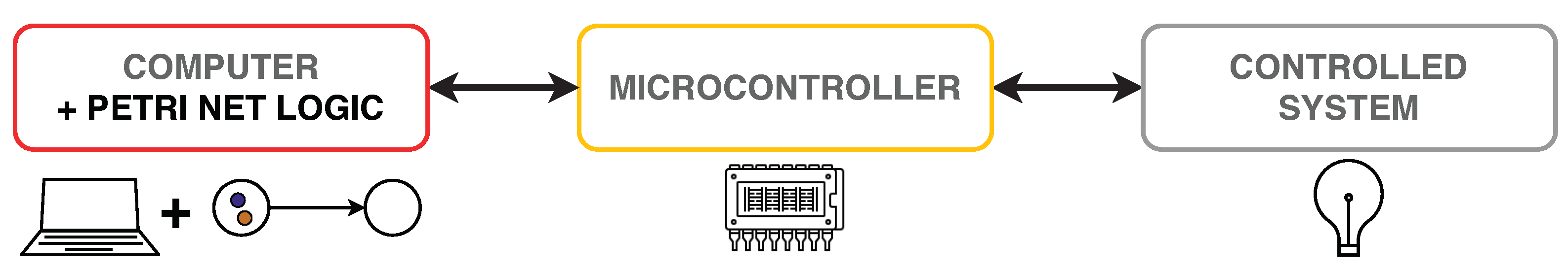
  • After launching the application, the user is given the opportunity to directly create and model a Petri net, which is a model of a particular selected event system, which the user has chosen to analyse and/or control.
  • Petri net modeling must meet at least the basic required mathematical formalisms, ideally this solution concept will be extended by other specific properties of Petri nets, which were the subject of the previous analysis.
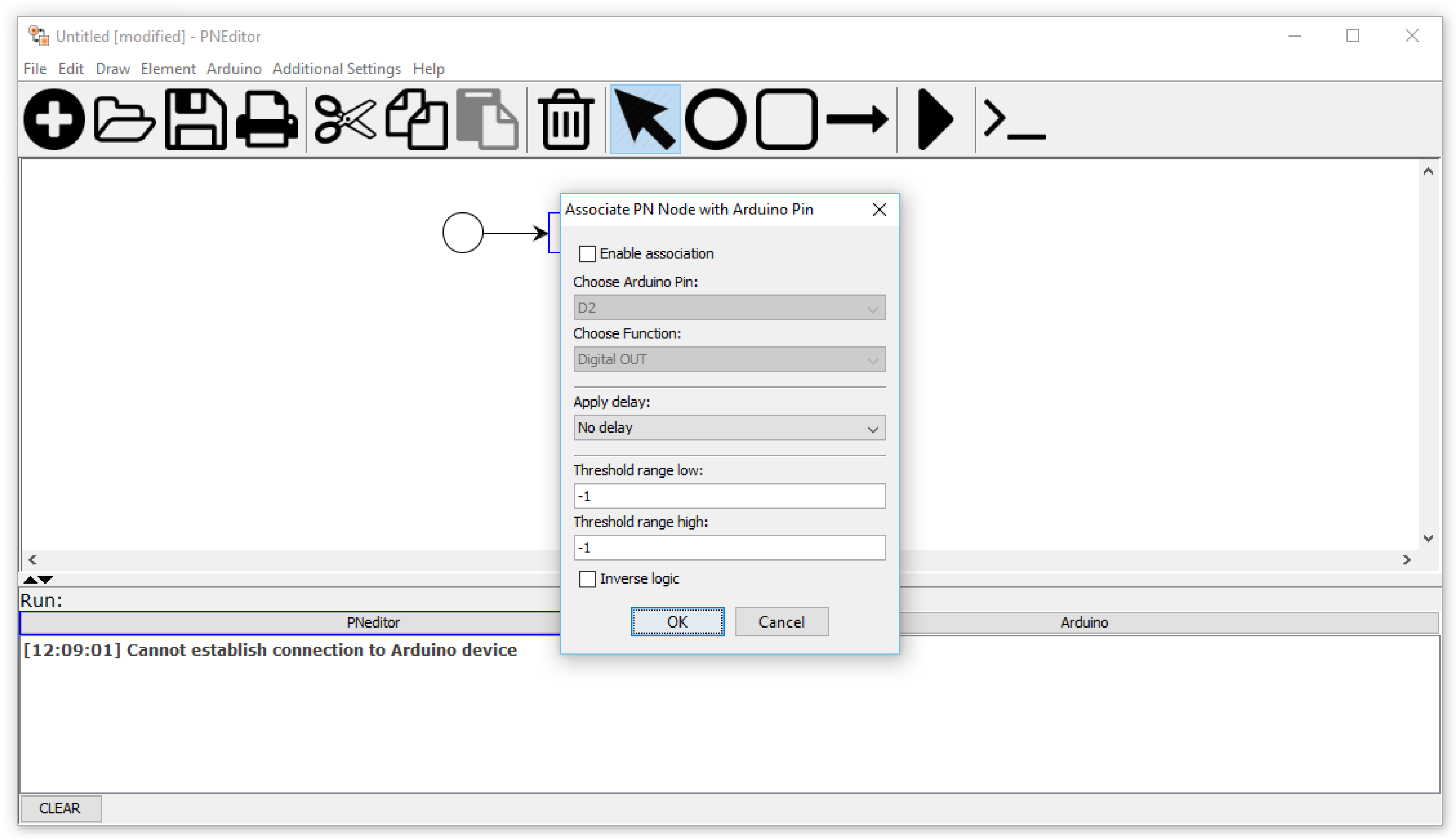
  • In case the user decides that the created model is final, he/she must be able to clearly associate the individual components of the Petri net with the control modules of the selected microcontroller.
  • The application must be able to process the choice of these dependencies and automatically adjust them to avoid possible collisions when defining different actions on one component.
  • The necessary functionality of the system must be the possibility of setting of specific values needed for proper communication with the microcontroller.
  • The system must be able to communicate with the selected microcontroller based on the selected parameters.
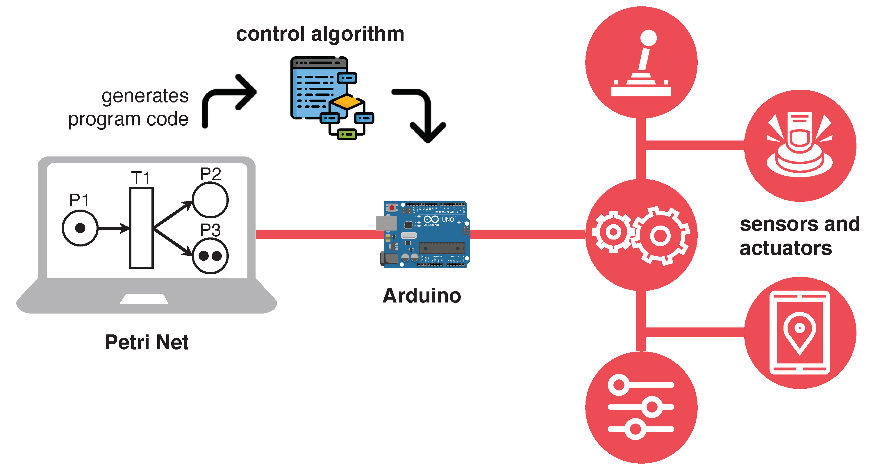
  • One of the essential functions is the creation of such an option in the system, by which the user can automatically generate a control logic algorithm based on the specific properties of the selected microcontroller and modelled Petri net.
  • It must be possible to upload the generated algorithm (program code) to the microcontroller.
  • The system will inform the user through the visualisation of text messages about the current ongoing activity and the result of the system status itself, in order to provide the user with an overview of whether the action was successful, or for what reason and in which step failed.
The scheme of the proposed and implemented solution can be seen in Figure 3. The application consists of two modules. The first is a tool that can be used to model and simulate a Petri net (PetriNet editor). The second is a module that generate program code based on the mathematical formalisms of the modeled Petri net. This code can be uploaded to the selected microcontroller (Arduino). Then, it can control the real hardware (sensors/actuators) connected to it.
The use-case diagram of the developed software tool is depicted in Figure 4.

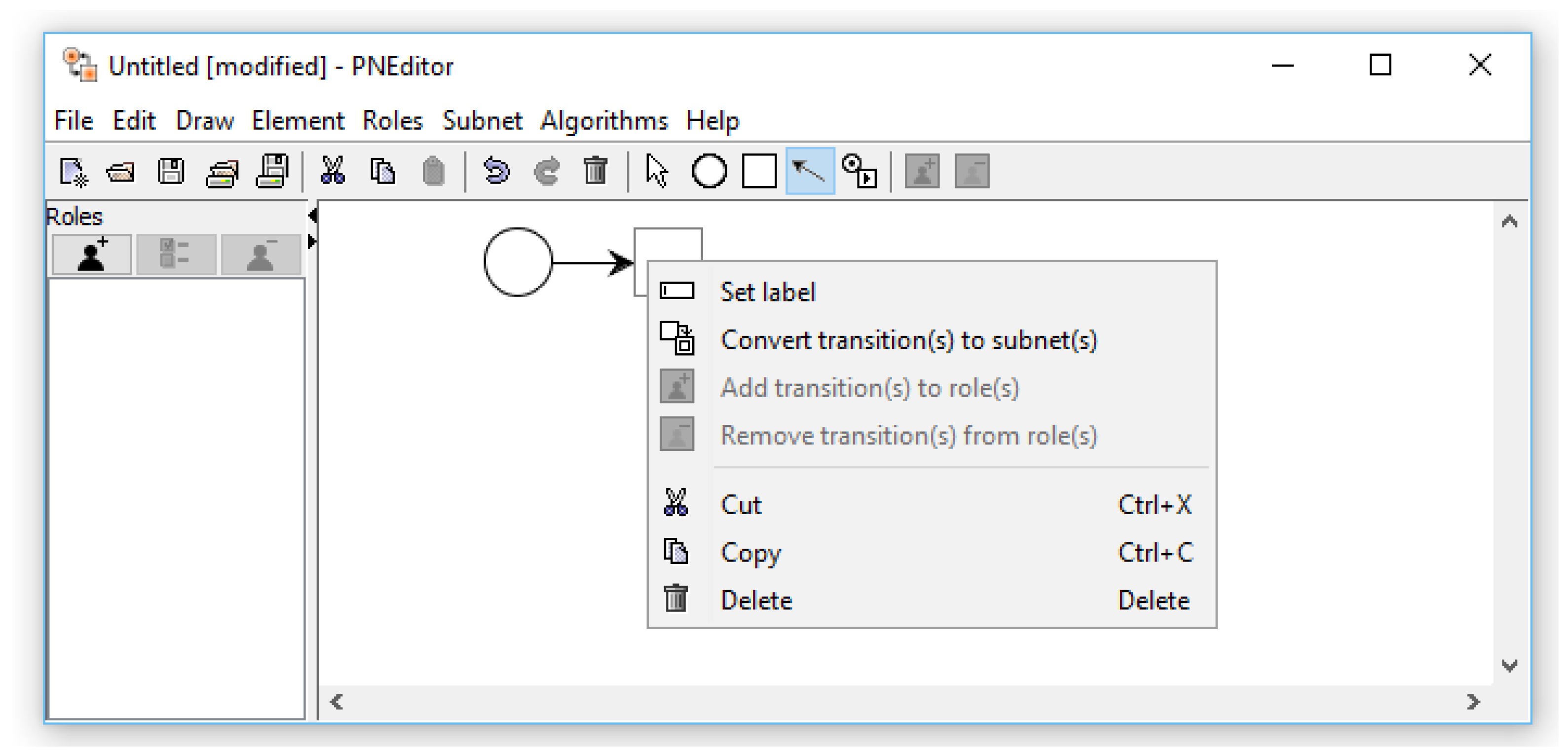
3.1.1. Presentation Layer—PetriNet Editor

As the basis of the presentation layer (GUI) of the application, we decided to use the modeling tool PNEditor, which was necessary to modify and adapt to the system designed by us. To illustrate, we present the following Figure 5. Here you can see the original PNEditor application, which we implemented our designed solution in.
The step of enabling the generation of the control algorithm itself is preceded by a set of dependencies that the user in the system is forced to perform. First of all, it is necessary to select the board for which the code is to be generated. We have implemented support for three types of Arduino boards, namely Nano, Uno and Mega 2560. It is also necessary to determine the parameters needed to create the correct communication path, which is the setting of the serial port through which the selected board will communicate with the computer. Part of this setting is also the possibility to specify whether the user wants to keep temporary files created during code generation in the directory structure of the application, and the choice of an extended compilation listing in the log.
Secondly, the basis for generating the control algorithm is the association of the Petri net with the individual components of the Arduino. We implemented the support of the association to the places and also the transitions of the Petri net. After right-clicking on the selected element, the user has the option to specify this association, which is specified by selecting the Arduino pin, which must be selected based on the required functionality. Support for digital and analog I/O (input/output) as well as specific components such as the servo motor and seven-segment display was successfully implemented. By selecting the required component, the availability of free pins on the board that can be associated is adjusted based on an agreed convention.
For example, the connection of a seven-segment display itself requires eight digital pins for control, but also one virtual control pin, which gives us the number that the display will currently display. It is called a virtual pin because it does not need to be physically connected to the board. However, it is necessary for the ability to transfer information and control the board. By selecting this component, the system automatically reserves the first nine digital pins of the board, which the user no longer has the possibility to associate with another element of the Petri net, thus avoiding collisions and conflicts in control. All user-defined properties are added to the output .pflow file under the individual added XML elements of the file structure.
The developed system generates code in C++ language, which represents a full-fledged Arduino project. Its output is a standard .ino file that meets the specifics of the Wiring library used by the Arduino IDE. It defines the exact structure of this file, which consists of two main program blocks, namely the function setup() and loop(). The first is performed only once. The second is performed continuously and repeatedly until the power supply to the board is disconnected. Without their presence, the program would end in error and never execute. The body of the logic for performing these functions is generated dynamically by the system based on the specifics of the modeled Petri net.
The system allows you to upload the generated control algorithm directly to the Arduino microcontroller. For this action, it is necessary to have the Arduino IDE installed on the computer (which the editor is running on), as the compilation and subsequent loading takes place by internal invocation of the command via the command line of the AvrDude utility, which is part of this IDE.
In order to avoid possible freezing of the main thread of the GUI application, the overall process of compilation and loading is realised by means of a special thread created specifically for this purpose. Figure 6 shows how the application looks like at present after the implementation of individual functionalities.

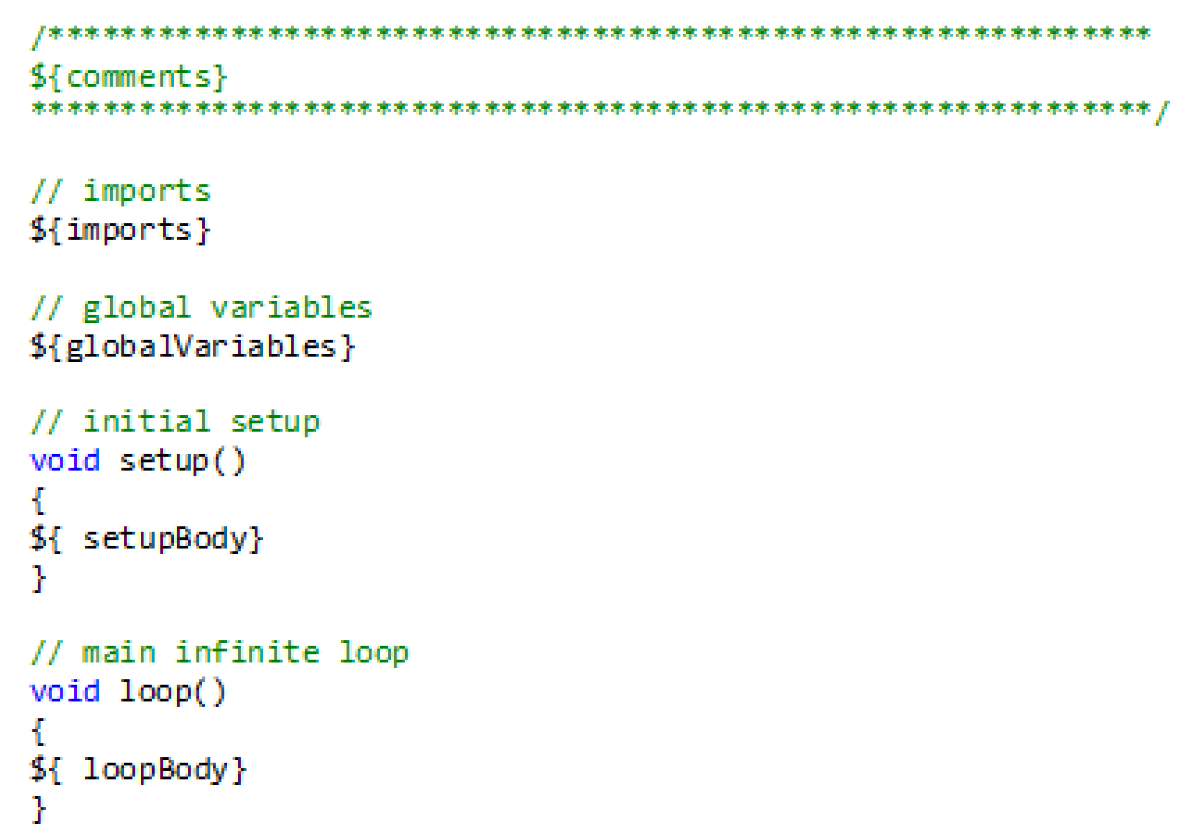
3.1.2. Application Layer—PetriNet Engine

The result of the first part of the implementation was the graphical interface providing the in Petri nets modelling functionality. The application layer of the program system (called PetriNet engine) provides conversion of the modelled Petri net to the program code realising control of the discrete event system. The PetriNet engine is the very core of the program enabling to generate a control algorithm.
The editor generates a C++ code with regard to specifics of the Arduino platform. The code generation emulates creation of a regular project for the Arduino IDE consisting of two phases. In the first phase, all the necessary .h and .cpp files are collected, which are pre-prepared and are part of the project.
These files contain, for example, definitions of the Place, Transition, Arc, and FiringScheduler classes. In the second phase, the main .ino file of the project is created on the basis of the currently modelled Petri net.
Because the creation of an .ino file is dynamic, a general template is used in which the generator writes the necessary code lines in the specified places (Figure 7).
The StrSubstitutor library from Apache is used to work with the template. All necessary information about the net status and settings for Arduino are stored in the Subnet and ArduinoManager objects. The resulting generation status, the code itself and all error messages are displayed in the log window in the PetriNet editor.
After a successful preparation of the whole necessary source code, this code can be uploaded to Arduino directly from the editor. The generated files are a full-fledged project for the Arduino IDE and it is possible to open and edit them in an external program.
The compilation and upload of the code is performed using the AvrDude program. AvrDude is a utility for working with the contents of ROM and EEPROM memories of AVR microcontrollers. AvrDude is part of the Arduino IDE program by default.
All statements and information messages created by AvrDude are captured and displayed in the PetriNet editor log window. In addition, the total time of compilation and upload of the project to Arduino is calculated and displayed.
The PetriNet editor stores Petri net information in an XML file. New elements were added to the existing XML structure of the original PNEditor output. On the global level of the XML Petri net structure, the arduinoManager element was added to store information about the board type, serial port number, selected time policy and transition fire strategy, and some other information about the compilation and upload process.
Each place and transition associated with an Arduino includes additional information in the arduinoNodeExtension element e.g.the pin number, the type of performed function and some other parameters. An example is shown in Figure 8.
In the PetriNet editor, it is possible to create two types of places and transitions—places and transitions associated with an Arduino pin, and places and transitions without association. This latter option has been retained for the sake of a greater flexibility in net modeling. Transitions of both types support time information. The time assigned to a transition can be deterministic or stochastic.
The PetriNet editor is used just for graphical modelling of the Petri net and does not implement any logic; the logic is implemented in the PetriNet engine—the second part of the presented solution. The design of the proposed prototype application able to implement the logic of Petri nets has faced several challenges in terms of functionality and possible scalability supported by new Petri nets aspects:
  • mapping of a formal Petri net model into an object language,
  • definition of an appropriate transition firing mechanism to ensure consistency and parallelism throughout the start-up period of the net,
  • conflict resolution in several possible executable transitions,
  • emulation of non-determinism of Petri nets,
  • support for timed Petri nets.
The PetriNet engine is implemented in C++ and considers Arduino as a target platform with limited computing and memory performance. The architecture of the program uses an object-oriented approach, which allows a relatively simple mapping of software components to Petri net elements (Figure 9).
The logic is not centralised, but distributed to the individual Petri net elements. The main components are Place, Transition, Arc and FiringScheduler. Due to partial common functionality, places and transitions have a common parent class. An important component is FiringScheduler which according to the chosen strategy resolves transition conflicts and determines which of the executable transitions will be fired.

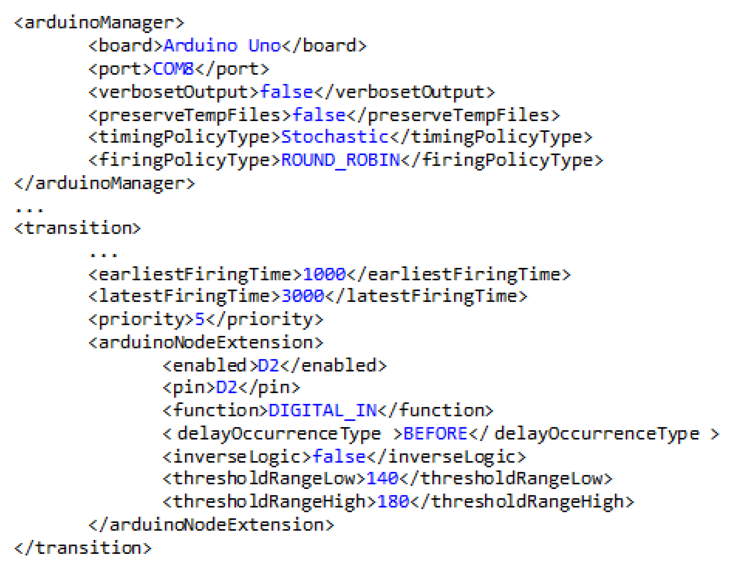
3.1.3. Transition Firing Strategy

In the main cycle of the program, the PetriNet engine goes through all the transitions and searches for those that are executable, and then, according to the chosen strategy, selects the next transition to be executed. Four strategies are implemented:
  • In the order the individual transitions were created in the editor—Each crawl of executable transitions starts from the first transition. As a result, for example, if the first transition is still executable, it will also be executed and no other transition will ever be selected to start.
  • By priority—Each transition carries information about the priority. The priority is any number in the range 0–32,767. The range is limited by the supported size of the int data type on Arduino boards with ATMega microcontroller. A transition with a higher number has a higher priority. In case of equality of priorities, the first strategy is taken into account.
  • In the order that takes into account the last running transition—Internally, the last running transition is stored and the transition with the following index is selected from the set of executable transitions. The difference from the first rule is that all executable transitions have the ability to be run.
  • Random—The next transition is selected randomly from the set of currently executable transitions.

3.1.4. Memory Optimisation

ATmega328 has 32 KB of flash memory, 2 KB of SRAM memory and 1 KB of EEPROM memory. From the numbers, it can be seen that the SRAM memory is small compared to the flash memory. When the SRAM memory is full, the program may behave unexpectedly. The memory had to be optimised for the PetriNet engine to run stably, as a simple Petri net consisting of one place and two transitions took up 89% of the SRAM memory. To optimise memory usage, the ability to move all strings from SRAM memory to flash memory was used. This is done using the approach provided by PROGMEM. PROGMEM is a variable modifier that tells the compiler to store the marked variable in flash memory.
In this way, the optimised memory showed high efficiency in the described application. Table 2 shows the memory usage before and after optimisation.
Without optimization, the relatively simple Petri net, consisting of 10 places and 10 transitions, could not be compiled. After optimisation, it was possible to compile a Petri net consisting of 40 places and 40 transitions.

3.1.5. Time Policy

The PetriNet engine provides simple support for timed Petri nets at the transition level, and two time strategies can be applied: deterministic and stochastic. Using the deterministic time policy, a user-defined delay is applied to the transition. Using the stochastic one, the user enters a time interval and the length of the delay is randomly selected from the entered interval. It is possible to associate an action over the selected Arduino pin with the duration of the transition: digital output or analog output realised by PWM (pulse-width modulation).
The start of the transition consists of two phases. In the first, tokens are taken from all input places according to the multiplicity of the respective arcs, and in the second, the appropriate number of tokens is added to the output places. PetriNet engine provides flexibility in delay placement. It can be placed:
  • Before the actual start of the transition—before the first phase—In this way, it is ensured that the new marking is applied to the input places only after a delay.
  • Between the first and second phase—In this case, the tokens are taken from the input places, a delay is applied, and only then the markings at the output places change.
  • After starting the transition—The time delay of the transition is applied only after a complete change of Petri net marking, but before selecting the next transition to start.

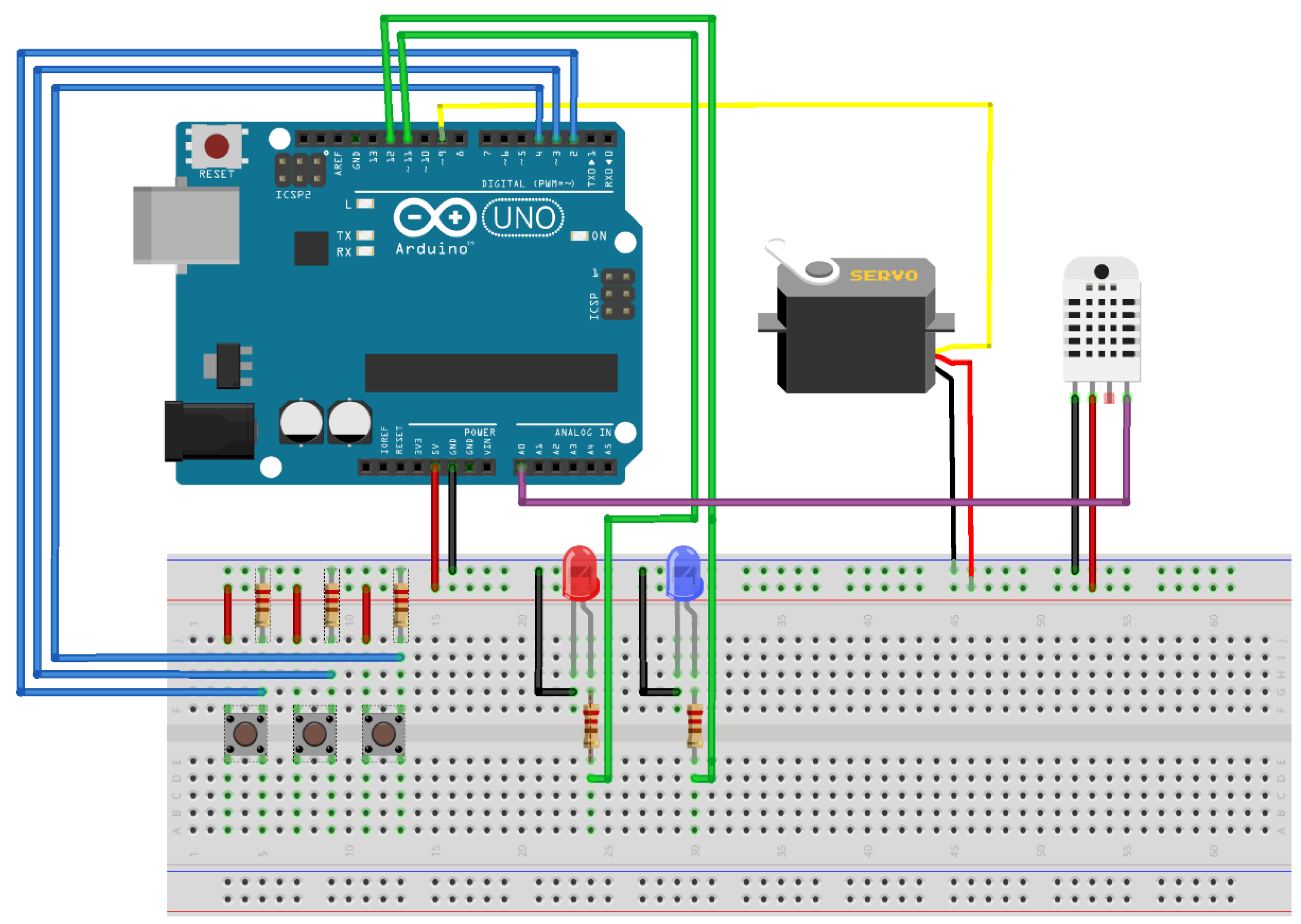
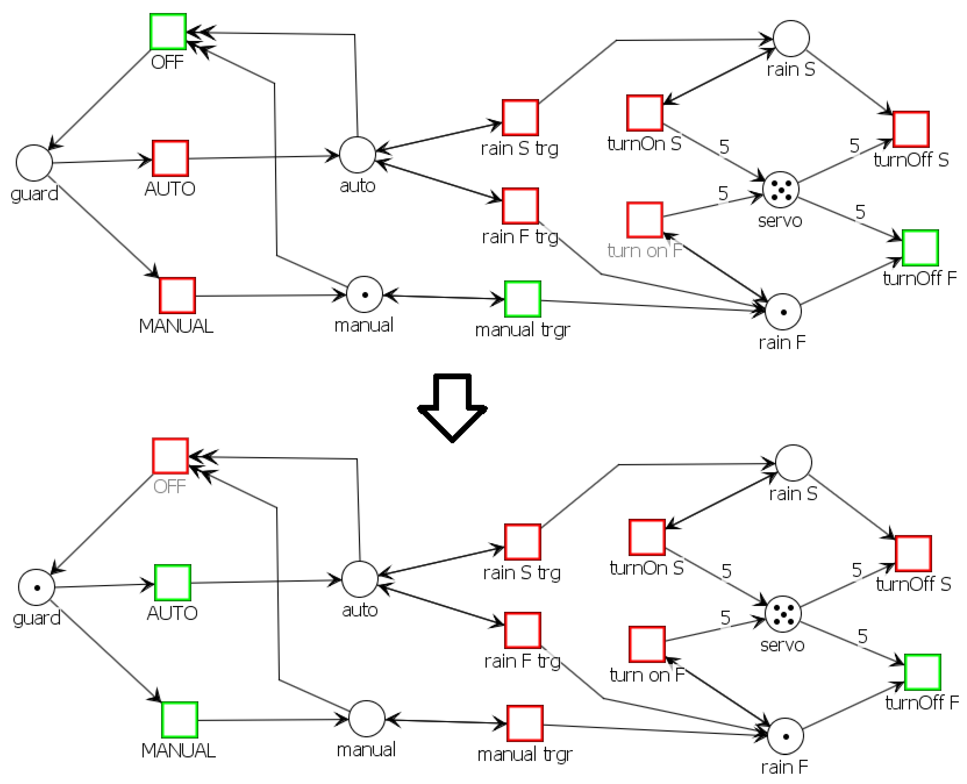
3.2. Case Study: Control of Laboratory Discrete Event System

For demonstration purposes, a Petri net for control of a car wiper system was modeled using the proposed application. In modern cars, wipers are able to work in both manual and automatic modes. In manual mode, switching the wipers on and off is usually controlled by a lever or a button. When the wipers work in automatic mode, the car’s control subsystem takes care of everything. Switching on, off, setting the wiper intensity according to the intensity of the rain is automatic and no intervention by the car driver is required. The only action required by the driver is to enable automatic mode.
The proposed control system implements all mentioned requirements. The Petri net representing this system uses several functions supported by the PetriNet engine. These are mainly Arduino-associated places and transitions, time transitions, priority transitions, capacity places, and reset arcs. The Petri net is shown in Figure 10. The graphical representation of Petri net is standard, more information can be found e.g., in [29]. The double arrow is used for reset arcs.
The capacities of places are:
  • guard - 1
  • auto - 2
  • manual - 2
  • rain S - 2
  • servo - 6
  • rain F - 2
The priorities of transitions are:
  • OFF - 4
  • AUTO - 0
  • MANUAL - 0
  • rain S trg - 1
  • rain F trg - 1
  • manual trgr - 1
  • turnOn S - 2
  • turn on F - 2
  • turnOff S - 3
  • turnOff F - 3
The system consists of three buttons—a button to start the automatic mode, to start the manual mode and to turn off the current mode. These buttons are represented by AUTO, MANUAL, and OFF transitions. The next component of the system is the rain sensor. It is a simple analog device that changes the size of the output signal according to the size of the sensor area, which is damp or covered with water. The transition rain S trg is activated if the rain intensity is within 30% of the range of the rain sensor. If the rain intensity is higher, the transition rain F trg is activated. The servo motor that drives the wiper is represented by a place named servo. A place named auto and a place named manual are associated with an LED. The blue LED indicates the activated automatic mode and the red LED indicates the manual mode.
The wiring diagram of the individual components with the Arduino Uno is shown in Figure 11.
After starting, the system is in an initial state, when it is possible to select automatic or manual mode by pressing the appropriate button. Depending on the selected mode, the corresponding LED lights up. By activating the MANUAL transition, i.e., by pressing the red button, the token is moved from the place guard to the place manual. The place manual is associated with the Arduino pin where the red LED is connected, so this LED lights up. There will be zero tokens in the place guard, this will ensure that automatic mode cannot be activated during manual mode. At the same time, the OFF transition becomes executable, because the place guard, which is its output place, has a capacity equal to one and at the same time there is no token in it.
In the state of the system, which is shown in Figure 12, there are two executable transitions in the Petri net. The OFF transition is associated with the Arduino pin where the white button is connected. Therefore, this transition will only be triggered if this button is pressed. The only executable transition is therefore the manual trg transition, and this transition will therefore be started automatically.
Starting the manual trg transition will change the marking of place rain F and there will be one token in it. This makes the transition turn on F executable. The turn on F transition has a higher priority than the manual trg transition, and will therefore be fired in the next iteration. Associated with this transition is a delay that represents the time during which the wiper is in the on position. Rotation of the servo motor to the desired position is realised by the capacity of the place and the multiplicity of the input arc. The rotation of the servo motor is directly proportional to the number of tokens in place with respect to its capacity.
Subsequently, the turn off F, which has the highest priority of the currently executable transitions, will be started. The delay associated with this transition represents the time when the wiper is off. This process is shown in Figure 13.
The analogous description applies to the automatic mode, with the difference that the actual start of the wiper is conditioned by the signal from the rain sensor.
It is possible to activate the OFF transition at any time, because it has the highest priority.
The OFF transition is connected by reset arcs to the manual and auto places, and thus its firing takes all tokens from the given places (Figure 14). This will make some transitions no longer executable. If the system is currently in a wiper-on state, setting transition firing priorities will ensure that the wiper cycle is completed before the system returns to its original state.
We can conclude that the ability of discrete event control with “PetriNet editor + PetriNet engine” was successfully verified and can be generalised for other applications. The provided discrete event control case study is a basic example. Researchers in discrete event control design can use it for different and even more complicated scenarios.
In manufacturing processes for Industry 4.0, time-driven and event-driven dynamics are combined. We propose individual parts of the manufacturing process to be characterised by cyber-physical states (e.g., pressure, velocity, position, temperature, etc.) described by time-driven dynamics, and by temporal states (e.g., operation start and stop times) described by event-driven dynamics. A hybrid system model for control of manufacturing processes represents the behaviour of dynamical systems which states can evolve continuously as well as instantaneously. Such systems arise when control algorithms that involve digital smart devices are applied to continuous-time systems, or due to the intrinsic dynamics (e.g., mechatronic systems with bumps, electrical and mechanical devices for switching control). Hybrid control based on discrete event control methods can be used to improve performance and robustness compared to conventional (PID) control [30]. In such case, using hybrid dynamics is unavoidable for modelling complex interactions between digital and analog components of a complex manufacturing system.
In practice, one important class of discrete event systems are automated storage and retrieval systems (AS/RS) which are an important part of logistics. Nowadays, there is a high demand for new modelling and control methods of such systems in automotive in Slovakia. Across continents, economic activity is gaining unprecedented dimensions. The consumer lifestyle of a majority of population requires production of large quantities of goods in a short time. The benefit of AS/RS consists mainly in saving the human capital, and in higher reliability. The research on AS/RS, their examples and modelling using Petri nets can be found in [13,14].
The Smart Industry concept is a national initiative in Slovakia aiming to transform and strengthen its industry; it is based upon using the Industry 4.0 methodology and the latest research activities in academia and practice mainly in automotive. Research and applications in this field are focused mainly on small and medium-sized enterprises whereby one of important features is the design of optimal architectures and hybrid control of individual subprocesses. An example of reference architecture of a workplace in which production is realised with minimum human intervention is shown in Figure 15.

4. Conclusions

The article presents an extension of the PNEditor named “PetriNet editor + PetriNet engine” able to generate a program code for a microcontroller. This new software tool enables to control discrete event systems using timed interpreted Petri nets thus supporting the the control paradigm according to which the Petri net control logic is implemented directly in the microcontroller. The main virtue of the upgraded software tool is its capability to control complex discrete event systems exploiting the Petri nets formalism able to support many challenging scenarios in modern production systems operating in the Industry 4.0 framework.
The contribution of the research to the field of smart manufacturing systems can be summarised as follows:
  • Development of the software application “PetriNet editor + PetriNet engine” supporting modelling and control of discrete event systems
    A new software application called “PetriNet Editor + PetriNet Engine”, based on the open-source Petri Net editor PNEditor, has been created for the support of modeling of systems using timed interpreted Petri Nets. As a result, it enables to implement control algorithms on Arduino-type microcontrollers and other compatible microcontrollers as well.
  • Verification of the developed software system on a laboratory plant
    To verify the developed application “PetriNet editor + PetriNet engine”, and demonstrate its capabilities to control discrete event systems a laboratory car wiper system was proposed based on Arduino Uno microcontroller. The respective Petri net was modelled in the developed “PetriNet editor + PetriNet engine”, and the designed control was demonstrated on the real-world discrete event system.
  • Verification of the developed original control methodology based on timed interpreted Petri nets
    Obtained results have proved that the “PetriNet editor + PetriNet engine” can be successfully used to control real plants; though the provided case study is just a basic example, the proposed procedure can be generalised for more complex applications and even more complicated scenarios. Hybrid systems for Industry 4.0 manufacturing processes are a combination of time-driven and event-driven dynamics. Compared with conventional (PID) control, the hybrid control based on discrete event control methods considerably improves controlled system performance and robustness because using hybrid dynamics is unavoidable to reflect the interplay between digital and analog components of a complex manufacturing system.
The scientific and application contributions as declared in the three above points describe the developed original modelling and control procedures and solutions for discrete event systems, and can further be modified for the next research and practice in Industry 4.0.

5. Patents

The system for control of discrete event using Petri nets mentioned in the article is protected by utility model number 7984 by Industrial Property Office of the Slovak Republic (https://wbr.indprop.gov.sk/WebRegistre/UzitkovyVzor/Detail/68-2017).

Author Contributions

E.K. proposed the idea in this paper and prepared the software application; O.H., P.D. and J.C. designed the experiments, E.K. and P.D. performed the experiments; O.H., R.L. and E.K. analyzed the data; E.K. wrote the paper; O.H., P.D., R.L. and J.C. edited and reviewed the paper; All authors have read and agreed to the published version of the manuscript.

Funding

This work has been supported by the Cultural and Educational Grant Agency of the Ministry of Education, Science, Research and Sport of the Slovak Republic, KEGA 038STU-4/2018 and KEGA 016STU-4/2020, and by the Slovak Research and Development Agency APVV-17-0190.

Acknowledgments

We would like to thank to Pavol Češek and Ladislav Briš for helping with programming the implementation.

Conflicts of Interest

The authors declare no conflict of interest.

References

  1. Planke, L.J.; Lim, Y.; Gardi, A.; Sabatini, R.; Kistan, T.; Ezer, N. A Cyber-Physical-Human System for One-to-Many UAS Operations: Cognitive Load Analysis. Sensors 2020, 20, 5467. [Google Scholar] [CrossRef] [PubMed]
  2. Blume, C.; Blume, S.; Thiede, S.; Herrmann, C. Data-Driven Digital Twins for Technical Building Services Operation in Factories: A Cooling Tower Case Study. J. Manuf. Mater. Process. 2020, 4, 97. [Google Scholar] [CrossRef]
  3. Kaid, H.; Al-Ahmari, A.; Li, Z.; Davidrajuh, R. Intelligent Colored Token Petri Nets for Modeling, Control, and Validation of Dynamic Changes in Reconfigurable Manufacturing Systems. Processes 2020, 8, 358. [Google Scholar] [CrossRef] [Green Version]
  4. Pombo, I.; Godino, L.; Sánchez, J.A.; Lizarralde, R. Expectations and limitations of Cyber-Physical Systems (CPS) for Advanced Manufacturing: A View from the Grinding Industry. Future Internet 2020, 12, 159. [Google Scholar] [CrossRef]
  5. Dotoli, N.; Fanti, M.; Meloni, C. Coordination and real time optimization of signal timing plans for urban traffic control. In Proceedings of the IEEE International Conference on Networking, Sensing and Control, Taipei, Taiwan, 21–23 March 2004; Volome 2, pp. 1069–1074. [Google Scholar] [CrossRef]
  6. Boschian, V.; Dotoli, M.; Fanti, M.; Iacobellis, G.; Ukovich, W. A Metamodeling Approach to the Management of Intermodal Transportation Networks. IEEE Trans. Autom. Sci. Eng. 2011, 8, 457–469. [Google Scholar] [CrossRef]
  7. Cong, X.; Fanti, M.; Mangini, A.M.; Li, Z. Decentralized Diagnosis by Petri Nets and Integer Linear Programming. IEEE Trans. Syst. Man Cybern. Syst. 2018, 48, 1689–1700. [Google Scholar] [CrossRef]
  8. Fanti, M.; Mangini, A.M.; Roccotelli, M.; Ukovich, W. A District Energy Management Based on Thermal Comfort Satisfaction and Real-Time Power Balancing. IEEE Trans. Autom. Sci. Eng. 2015, 12, 1271–1284. [Google Scholar] [CrossRef] [Green Version]
  9. Heiner, M.; Herajy, M.; Liu, F.; Rohr, C.; Schwarick, M. Snoopy—A unifying Petri net tool. In Proceedings of the International Conference on Application and Theory of Petri Nets and Concurrency, Hamburg, Germany, 25–29 June 2012; pp. 398–407. [Google Scholar]
  10. Drath, R. Description of hybrid systems by modified petri nets. In Modelling, Analysis, and Design of Hybrid Systems; Springer: Berlin/Heidelberg, Germany, 2002; pp. 15–36. [Google Scholar]
  11. Chouikha, M.; Decknatel, G.; Drath, R.; Frey, G.; Müller, C.; Simon, C.; Wolter, K. Petri net-based descriptions for discrete-continuous systems. Automatisierungstechnik Methoden und Anwendungen der Steuerungs- Regelungs-und Informationstechnik 2000, 48, 415. [Google Scholar] [CrossRef]
  12. Drighiciu, M.A.; Cismaru, D.C. Modeling a Water Bottling Line Using Petri Nets; Annals of the University of Craiova, Electrical Engineering Series; Universitaria Craiova: Romania, Romania, 2011. [Google Scholar]
  13. Kučera, E.; Hrúz, B. Modelling of AS/RS using hierarchical and timed coloured Petri nets. In Proceedings of the 23rd International Conference on Robotics in Alpe-Adria-Danube Region (RAAD), Smolenice, Slovakia, 3–5 September 2014; pp. 1–8. [Google Scholar] [CrossRef]
  14. Kučera, E. Modelling of storage/manufacturing systems using coloured petri nets. In Proceedings of the 17th Conference of Doctoral Students, Bratislava, Slovak Republic, 25 May 2015; Volume 25. [Google Scholar]
  15. Giua, A.; Seatzu, C.; Sessego, F. Simulation and analysis of hybrid Petri nets using the Matlab tool HYPENS. In Proceedings of the 2008 IEEE International Conference on Systems, Man and Cybernetics, Singapore, 12–15 October 2008; pp. 1922–1928. [Google Scholar]
  16. Davidrajuh, R. Modeling Discrete-Event Systems with Gpensim: An Introduction; Springer International Publishing: New York, NY, USA, 2018. [Google Scholar]
  17. Liu, B. Simulation of Network Intrusion Detection System with GPenSim. Master’s Thesis, University of Stavanger, Stavanger, Norway, 2011. [Google Scholar]
  18. Davidrajuh, R.; Skolud, B.; Krenczyk, D. Gpensim for performance evaluation of event graphs. In Advances in Manufacturing; Springer: Cham, Switzerland, 2018; pp. 289–299. [Google Scholar]
  19. Bonet, P.; Lladó, C.M.; Puijaner, R.; Knottenbelt, W.J. PIPE v2. 5: A Petri net tool for performance modelling. In Proceedings of the 23rd Latin American Conference on Informatics (CLEI 2007), San Jose, Costa Rica, 9–12 October 2007. [Google Scholar]
  20. Mostermany, P.J.; Ottery, M.; Elmqvistz, H. Modeling Petri Nets as Local Constraint Equations for Hybrid Systems Using Modelica. 1998. Available online: http://citeseer.ist.psu.edu/359408.html (accessed on 1 August 2020).
  21. Fabricius, S.; Badreddin, E. Modelica library for hybrid simulation of mass flow in process plants. In Proceedings of the 2nd International Modelica Conference, Oberpfaffenhofen, Germany, 18–19 March 2002; pp. 225–234. [Google Scholar]
  22. Pross, S.; Bachmann, B.; Stadtholz, A. A petri net library for modeling hybrid systems in openmodelica. In Proceedings of the Modelica Conference, Como, Italy, 20–22 September 2009. [Google Scholar]
  23. Pross, S.; Bachmann, B. Pnlib-an advanced petri net library for hybrid process modeling. In Proceedings of the Modelica Conference, Munich, Germany, 3–5 September 2012. [Google Scholar]
  24. Markiewicz, M.; Gniewek, L. A Program Model of Fuzzy Interpreted Petri Net to Control Discrete Event Systems. Appl. Sci. 2017, 7, 422. [Google Scholar] [CrossRef] [Green Version]
  25. Mazári, J.; Juhás, G.; Mladoniczky, M. Petriflow in actions: Events call actions call events. Algorithms Tools Petri Nets 2018, 2, 21–26. [Google Scholar]
  26. Kučera, E.; Haffner, O.; Drahoš, P.; Cigánek, J.; Leskovský, R.; Štefanovič, J. New Software Tool for Modeling and Control of Discrete-Event and Hybrid Systems Using Timed Interpreted Petri Nets. Appl. Sci. 2020, 10, 5027. [Google Scholar] [CrossRef]
  27. Steiner, H.C. Firmata: Towards making microcontrollers act like extensions of the computer. In Proceedings of the NIME, Pittsburgh, ON, Canada, 3–6 June 2009; pp. 125–130. [Google Scholar]
  28. MIDI Association: (2016) Summary of Midi Messages. Available online: https://www.midi.org/specifications/item/table-1-summary-of-midi-message (accessed on 1 August 2020).
  29. Hrúz, B.; Zhou, M. Modeling and Control of Discrete-Event Dynamic Systems: With Petri Nets and Other Tools; Springer Science & Business Media: New York, NY, USA, 2007. [Google Scholar]
  30. Kos, T.; Huba, M.; Vrančić, D. Parametric and Nonparametric PI Controller Tuning Method for Integrating Processes Based on Magnitude Optimum. Appl. Sci. 2020, 10, 1443. [Google Scholar] [CrossRef] [Green Version]
Figure 1. Basic scheme of proposed solution—Petri net’s logic in microcontroller [26].
Applsci 10 07662 g001
Figure 2. Basic scheme of proposed solution—Petri net’s logic in PC [26].
Applsci 10 07662 g002
Figure 3. “PetriNet editor + PetriNet engine”—Scheme of proposed and implemented solution.
Applsci 10 07662 g003
Figure 4. “PetriNet editor + PetriNet engine”—Use-case diagram.
Applsci 10 07662 g004
Figure 5. GUI of original PNEditor.
Applsci 10 07662 g005
Figure 6. GUI of developed extension of PNEditor named PetriNet editor.
Applsci 10 07662 g006
Figure 7. Template of .ino file.
Applsci 10 07662 g007
Figure 8. Part of the XML file describing the connection to Arduino.
Applsci 10 07662 g008
Figure 9. PetriNet engine—class diagram.
Applsci 10 07662 g009
Figure 10. Petri net for control of laboratory car wiper system.
Applsci 10 07662 g010
Figure 11. Scheme of laboratory car wiper system.
Applsci 10 07662 g011
Figure 12. Petri net for control of laboratory car wiper system–initial marking and marking after starting manual mode.
Applsci 10 07662 g012
Figure 13. Petri net for control of laboratory car wiper system—the action of wiping.
Applsci 10 07662 g013
Figure 14. Petri net for control of laboratory car wiper system—turning off the manual mode.
Applsci 10 07662 g014
Figure 15. Possible architecture for small and medium enterprises consists of storages, cognitive robots, hybrid control, CNC machines, and laser quality testing.
Applsci 10 07662 g015
Table 1. Comparison of two concepts of system control using Petri nets [26].
Petri net Logic in PCPetri Net Logic in Microcontroller
limited capability of real-time controlreal-time control
much more computation and memory resources availablelimited computation and memory resources
code in microcontroller does not need recompilingduring development repeated compiling is needed
PC must be still onlineindependence of control unit
Table 2. The use of memory without optimisation and with optimisation.
Number of
Places
Number of
Transitions
Use of Memory without OptimisationUse of Memory with Optimisation
FLASHSRAMFLASHSRAM
1012 308 B
(38 %)
1 812 B
(88 %)
13 328 B
(41 %)
444 B
(21 %)
0112 178 B
(37 %)
1 832 B
(89 %)
13 622 B
(42 %)
444 B
(21 %)
1112 822 B
(39 %)
1 842 B
(89 %)
14 240 B
(44 %)
452 B
(22 %)
2213 204 B
(40 %)
1 856 B
(90 %)
14 672 B
(45 %)
468 B
(22 %)
3313 528 B
(41 %)
1 872 B
(91 %)
15 100 B
(46 %)
484 B
(23 %)
5514 248 B
(44 %)
1 904 B
(92 %)
15 958 B
(49 %)
518 B
(25 %)
8815 286 B
(47 %)
1 954 B
(95 %)
17 314 B
(53 %)
574 B
(28 %)
101016 166 B
(49 %)
2 040 B
(99 %)
18 042 B
(55 %)
606 B
(29 %)
151517 748 B
(55 %)
2 068 B
(100 %)
19 994 B
(61 %)
690 B
(33 %)
202019 500 B
(60 %)
2 152 B
(105 %)
22 226 B
(68 %)
782 B
(38 %)
404026 688 B
(82 %)
2 508 B
(122 %)
29 730 B
(92 %)
1 182 B
(57 %)
Publisher’s Note: MDPI stays neutral with regard to jurisdictional claims in published maps and institutional affiliations.

