1. Introduction
The popularization of new complicated methods of imaging diagnostics allows increasing the detection of neoplastic changes in the kidneys and other kidney diagnoses. Since very often all changes are characterized by the absence of any symptoms, quick and effective computer-aided diagnostics are very important. Currently, contrast computed tomography is the “gold standard” in the diagnosis of kidney diseases. It allows the assessment of kidneys and abnormal morphological changes. The purpose of using CT imaging is to determine the size of the tumor and its location. There are basic components that determine the possibility of visualizing abnormalities in the structure of the kidney. Focal changes in the kidneys may be a simple cyst or even an obvious cancerous tumor. The changes have a whole range of different morphological variants and knowing them is very useful in the final diagnosis of a specific disease. The importance of tomography as a helpful tool in the detection of invisible and non-palpable tumors is growing especially in increasingly used renal-sparing treatment. This article focuses on the presentation of the computed-aided method of automatic kidney boundary detection in CT images. This is a very important task from the differentiation of the kidney shape.
Diagnostic Evaluation of the Kidneys
Unfortunately, the widely used medical history and physical examinations are of limited value in identifying kidney changes, for example, in looking for a tumor. Kidney diseases remain asymptomatic for a long time and are undetectable on physical examination. Some non-obvious symptoms associated with kidney tumor development may be caused by local growth, bleeding, or distant metastases. The most characteristic symptoms include symptoms such as hematuria, pain in the lumbar region, and pathological resistance in the abdominal cavity. This is the so-called classic triad that is now found rarely among about 7% of patients. This condition proves the high clinical advancement of the tumor. The popularization of imaging diagnostic methods significantly increased the detection of asymptomatic kidney tumors. The analysis of data from the United States (NCI Surveillance Epidemiology and End Results Program—SEER) for the years 1983–2002 indicates an increase in the incidence of kidney tumors depending on their dimensions. The GBD study also estimated that, in 2017, 1.23 million people died from kidney disease and disease was the 12th leading cause of death [
1]. Currently, about 60–90% of lesions are detected accidentally during routine examinations due to non-specific ailments [
2,
3,
4]. Ultrasonography (USG) is most often the first imaging examination performed when a kidney tumor is suspected. Unfortunately, due to the limited accuracy of the examination, patients are referred to a more focused computed tomography examination. Not only is the number of accidentally detected malignant neoplasms increasing. In a large series of surgically treated patients, about 10–20% of the removed tumors turn out to be benign [
2,
5,
6]. The likelihood of a benign nature increases with decreasing tumor dimensions [
6].
2. Problem Statement of Renal Localization
The current classification of WHO kidney tumors from 2004, and the International Society of Urological Pathology (ISUP) from 2013, distinguishes over 60 histological units [
4,
7].
The basic factor influencing the further management of the patient is the assessment of the nature of the identified pathology and its clinical advancement. An essential element of the diagnostic process is the differentiation of benign lesions that can be monitored from malignant lesions that should be treated surgically. To determine the proper treatment method: organ-sparing surgery, radical nephrectomy, or thrombectomy, the correct assessment of the local tumor advancement is necessary.
Contemporary computer tomographs (CT scanner) perform up to 2,000,000 projections of high resolution, even up to tens of micrometers. Multi-row computed tomography becomes the standard. The number of receiving elements has been increased to 64. Companies have already introduced 128 and even 256-row scanners. The introduction of two X-ray tubes is the next stage of development. The examination time is significantly shortening, decreases reduction of X-rays and at the same time much more data, allowing for more accurate imaging of the examined organs are obtained for the better spatial projection of the image (3D).
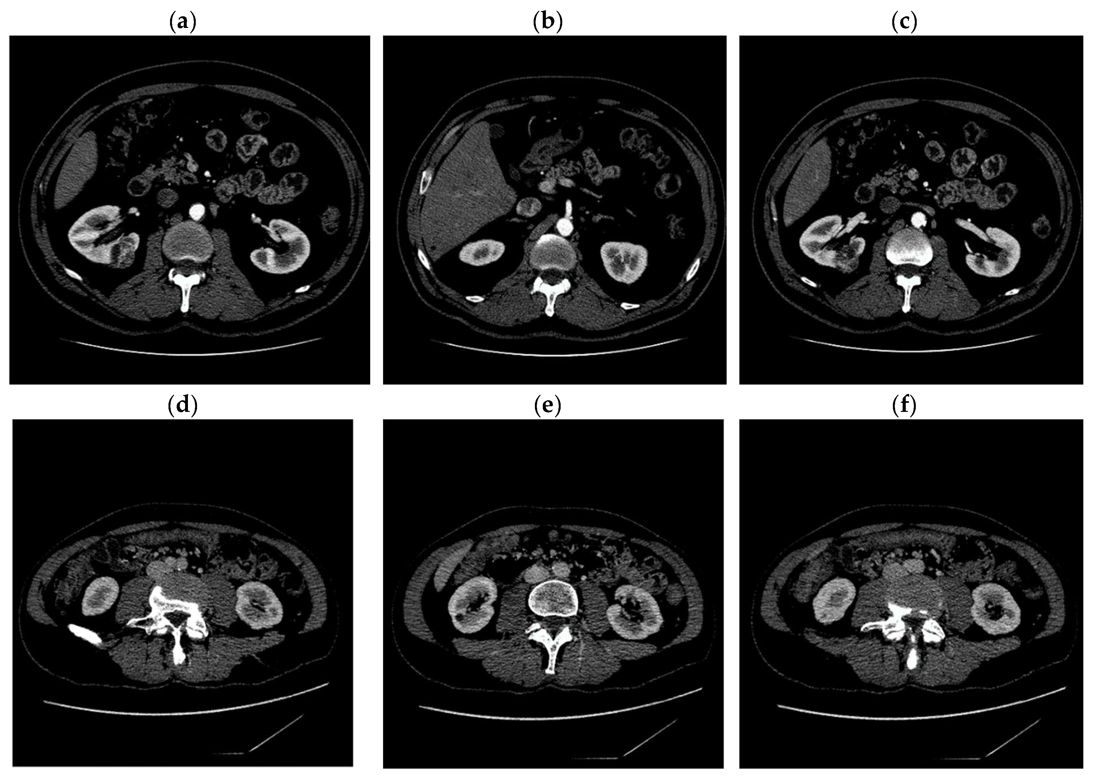
Digital images obtained as a result of computed tomography, used in our experiments, have the dimensions of 512 × 512 pixels. Exemplary CT images are shown in
Figure 1.
The visual assessment of the kidney condition is done manually by a doctor who must look at hundreds of scans and carry out a detailed description. From computer methods of supporting medical diagnostics, it is very important to develop modern techniques and tools for automatic or semi-automatic kidney location. The real-time computer software will reduce the time of image analysis and allow for more effective diagnostics. With many images, the likelihood of human error increases. Thanks to algorithms for the automatic location of the kidneys, we can give doctors a very useful tool. In this paper, we focus on techniques for an automatic location of kidneys along with finding the outline of the kidney on each slice, regardless of its location in the abdominal region.
3. Methods of Automatic Renal Localization
Computer techniques of automatic image segmentation are currently one of the most important issues in medical technology [
8]. The increase in the number of CT images in the diagnosis and treatment of CT diseases is a necessary step in a precise treatment planning. However, different tissues have different sizes and shapes from person to person, and the grayscale similarity between the kidney and adjacent tissues, such as the liver and spleen, is very large. Therefore, the segmentation of the kidneys is a difficult and demanding task.
In recent years, many solutions for renal segmentation have been developed. Good segmentation results were obtained by the system based on the deformable model [
9,
10]. Other proposed solutions include methods based on clustering and area expansion [
8]. Methods based on fuzzy segmentation [
11] are being constantly developed. A whole group of distinct methods uses machine learning techniques. Among these solutions, one can find solutions based on U-net neural networks [
12,
13,
14,
15] which are very often used in medical image segmentation tasks.
Solutions based on U-net allow us to obtain satisfactory results and this is a direction worth further development. The major drawback of these techniques is that they require post-processing to obtain a binary response. The U-net network returns the results in an ambiguous form, which must be converted into a black and white image. Simple thresholding techniques fail, and the high complexity of post-processing methods makes these hybrid solutions slow. In this article, we present a new approach to kidney localization using the extended maxima transformation. The proposed solution allows for satisfactory results of kidney location (84%). Additionally, it has been proposed to extend the system with U-net pre-processing of areas, which increases the accuracy of the complete system of kidney localization to 89%. The extended maxima transformations and U-Net preprocessing system presented in our work requires the use of prediction of just one slice. Further processing of the remaining slices is based on morphological operations, which gives a significant time saving, confirmed by experimental tests.
3.1. Extended Maxima Transform
In this section, we introduce our proposition of the “slice scanning procedure”, used to locate both kidneys in the image. The description provided in this section concerns the identification of the right kidney only. The identification of the left kidney is the same, except for a different starting point. The initial assumption of the algorithm is as follows:
The input algorithm loads CT images numbered from 1 to .
Each CT image is a raw CT slice containing right (or left) kidney.
Slice labeled as , means the middle CT image. In this image, the boundary of the kidney has the largest (or almost largest) area. The CT end-slices at the position or , denoted and , contain the smallest kidney.
A binary mask denoted as , is a predefined area that defines the starting area of the algorithm. The starting area determines the area where the kidney is searched in a raw Ct image.
The procedure for locating the kidney in the image begins with a slice
. We use a technique based on extended-maxima transform for kidney detection. The Extended-maxima transform is the regional maxima of the H-maxima transform. As regional maxima, we denote connected components of pixels with a constant intensity value. All pixels belonging to the external boundary have a lower value [
16].
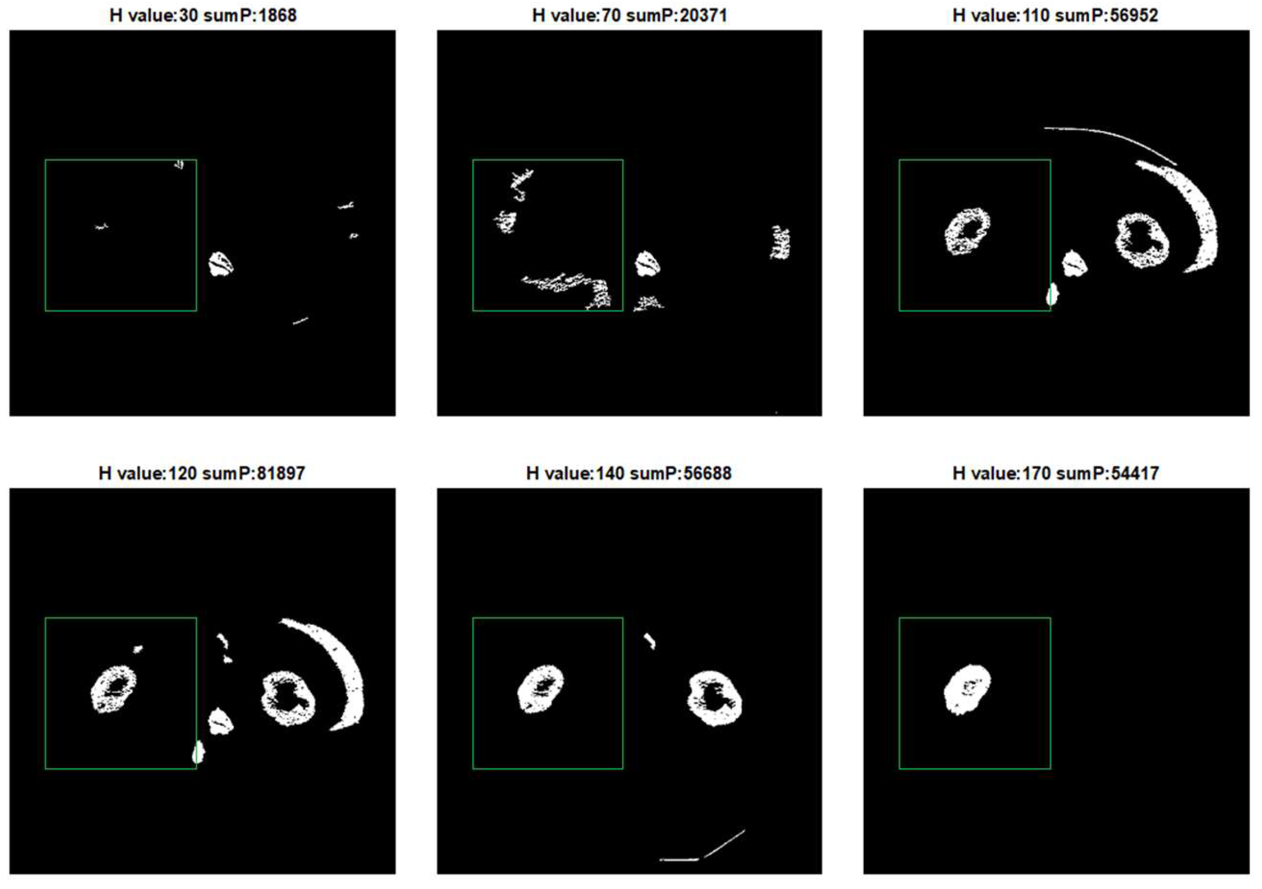
We perform extended-maxima transform for all possible parameters H = [10, 20, 30, …, 200]. For each result of extended-maxima transform:
Leave the top 10 biggest objects.
Count how many objects completely fit in . Mark the number of objects as .
For each object, if it intersects boundary, remove it.
Calculate according to formula (1).
where
R is reconstruction by dilation of image
from
−
H. Regional maxima are connected components of pixels with a constant intensity value, and whose external boundary pixels all have a lower value [
17]. We use pixel connectivity: 8.
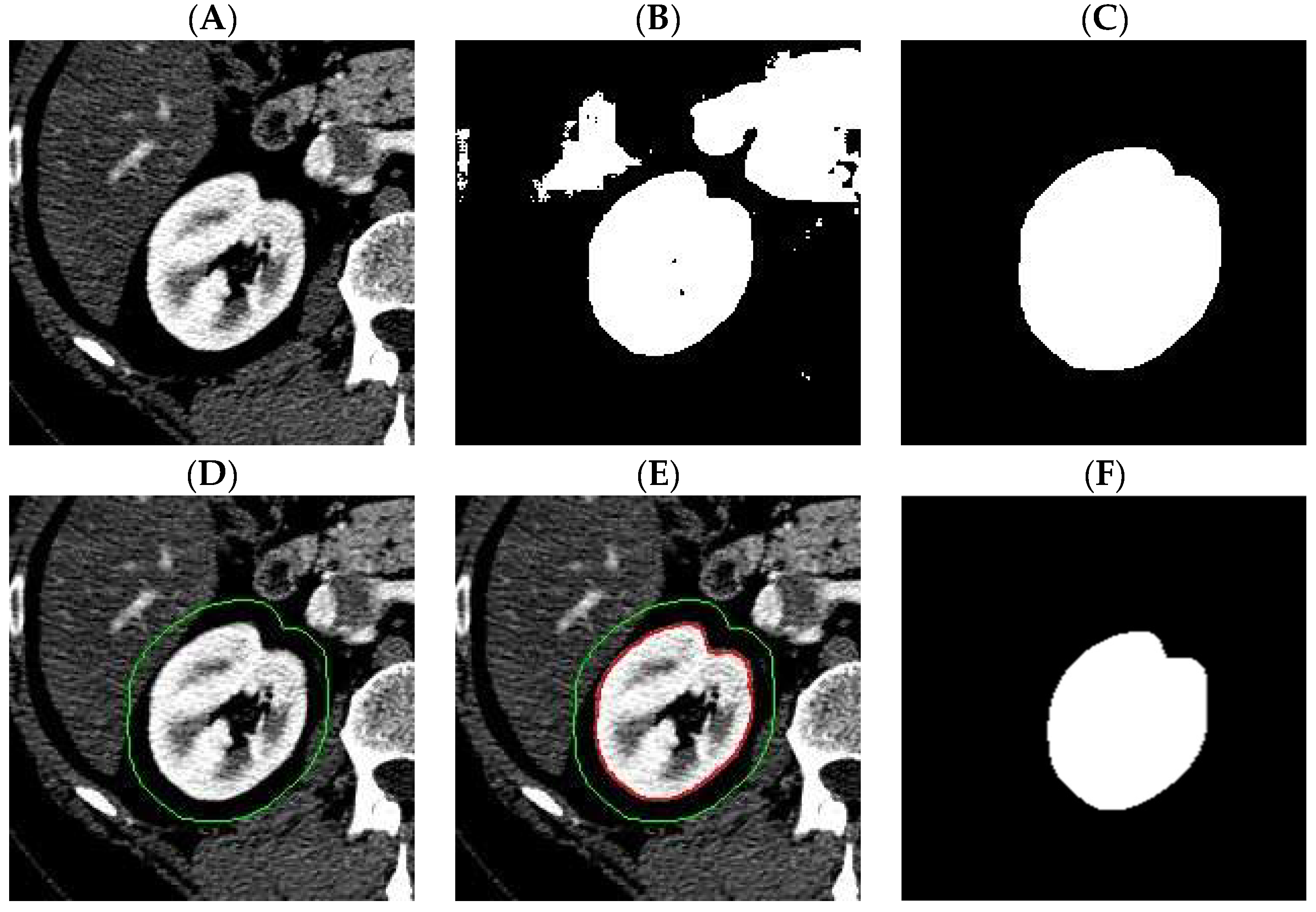
Figure 2 shows the result of the extended-maxima transform operation for selected
parameters. For each value of H, a
value has been calculated. In the given example, we used as
a square with the upper left corner position (x, y) = (50,175) and a side length of 200 pixels.
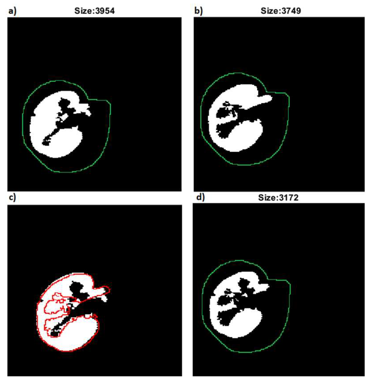
The next step is to leave one result for which
is the highest and fill the holes and denote as
the value of
. In the next step, the extended-maxima transform is executed again but in the raw
image. Each time algorithm is executed, the circularity coefficient
is calculated and the result of the operation is removed from the image. According to this procedure, we generate
number of masks which are potential candidates for the final kidney mask. Finally, the mask of the highest
value is selected. The result of the next five steps is shown in
Figure 3.
The described procedure allows us to find the boundary of the kidney in the
image. The algorithm for kidneys detection in the remaining slices
is presented in the subchapter “
Section 3.2 Slice scanning algorithm”. Automatic calculation of the starting area based on neural network is described in the subchapter “
Section 3.3 U-Net assisted initial localization”.
3.2. Slice Scanning Algorithm
The kidney identification procedure described in
Section 3.1 allows finding the kidney in the middle slice—
. The procedure of finding kidneys boundaries in remaining slices is based on the fact that the mask of the kidney in the
image is used for the detection of the kidney in the
and
image. The complete procedure for detecting kidneys in all
images starts with
slice. Then slice scanning is performed in two directions:
Middle–top: ;
Middle–bottom: .
For each
or
image, the procedure using extended-maxima transform, described in 3.1, is performed. According to this procedure, for each
or
image we generate
number of masks which are potential candidates for kidney masks. This time we do not select the mask with the highest PP factor as we did in
Section 3.1.
For each candidate mask— we calculate new mask using operation according to the scanning direction. Finally, we select with the largest size (the most overlapping with the previous mask).
In
Figure 4, the succeeding steps of slice scanning are shown.
3.3. U-Net Assisted Initial Renal Localization
Procedure generating mask using the technique described in
Section 3.1 and
Section 3.2 requires the correct calculation of the starting search area
. In
Figure 3, the starting area has been marked as a square. For a different image size, different
size and shape are optimal. The experimental results show that the
is smaller and at the same time kidney is fully contained in
the better results of extended maxima transform we can generate. To meet these assumptions, a procedure of
calculation was implemented using the U-Net neural network. U-Net is a multi-layer network. In this type of network, the input layer consists of the dimensions of the input data [
18]. In the learning process, images were cropped to the size of 256 × 256, considering the most common location of the kidneys. Input data were then normalized according to rule (2).
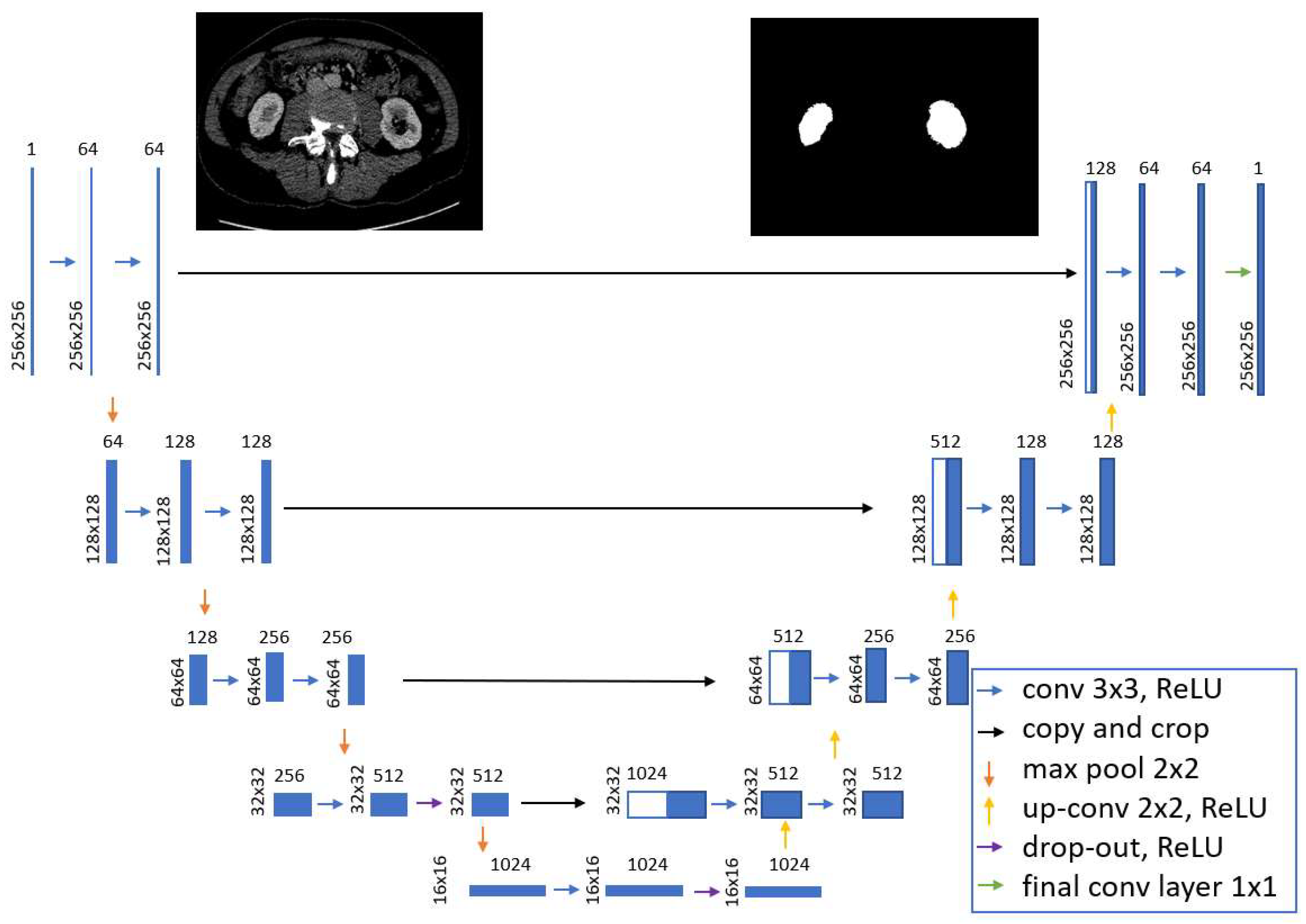
The diagram of the U-Net model used in the tests is presented in
Figure 5.
Each layer is shown as a blue block and corresponds to a multi-channel representation of the output image of the previous layer. On the left side of the block, the size of the image representation (height width) is marked. The number of channels is shown above the block. White blocks correspond to the copied image representation from the deeper layer. Arrows indicate operations performed on images. The constructed model consists of the input layer (single-channel image), convolutional layers with the ReLU activation function, filter size 3 × 3, sampling layers with a maximum operation with a filter size of 2 × 2, layers of inverse weave with a filter size of 2 × 2, dropout layers, the operation of copying the output images from deeper layers, a convolution layer with an activation function, with a filter size of 1 × 1, the output layer: single-channel grayscale image.
The output image of the model consists of values in the range ⟨0.1⟩, so to obtain a binary image, the prediction should be binarized using the threshold
(3):
Finding the optimal value for the cut-off point
T is a very difficult task. There is no single optimal value of
T even for a single CT image. It is impossible to determine the common value of
T for all slices. Many studies use techniques of dynamic determination of
based on techniques such as ROC analysis, Dice analysis, or based on precision and sensitivity parameters calculation [
19,
20,
21]. In our study, the
T threshold was selected to obtain the highest possible sensitivity. The output images obtained by the network are highly redundant. Finally, morphological operations are performed on the image: closing and dilatation with a 10 px disc. The area found this way is treated as the starting area
for the kidney detection algorithm described in
Section 3.1.
3.4. Complete Renal Localization System
This section introduces a complete system for the automatic detection of kidneys’ boundaries in CT images. The first step of the system is to calculate
. This step was performed using the U-Net neural network described in
Section 3.3. Once the
is calculated, the kidney localization procedure described in
Section 3.1 is performed using the extended maxima transform. The calculation for the kidney boundary is performed using the previously found
. After the system finds the exact boundary of the kidney in the middle slice
, the slice scanning procedure described in
Section 3.2 is performed. This procedure continues until all images have been scanned in the top and bottom directions. A complete diagram showing all the key steps of the system is presented in
Figure 6.
Figure 7 shows the visualization of the results in the individual steps of the algorithm.
4. Numerical Results
Numerical results were performed to evaluate the presented system. For the U-Net network we applied the parameters listed in
Table 1.
The images used in the learning process were manually marked by an expert from the Military Institute of Medicine in Warsaw, Poland. In total, 90 cases were used for preparation of the model’s parameters for the learning data and 48 cases were analyzed in the testing process. Each case contained between 32 and 210 scans. A total of 1692 CT images were tested. The tested images differed from each other in size, location, and shape of the kidney. The images differ in sharpness and pixel intensity levels. Numerical experiments were performed to evaluate the quality of the complete system described in
Section 3.4. Additionally, the influence of the
initial detection on the kidney mask detection was examined.
Table 2 presents the results grouped into 16 positions. Each group contains three cases from 70 to 400 slices. To determine the F1-score of the presented system, the following measure of F1-score
was used according to the Formula (4).
According to the above formula:
Tp—true-positive specifies the number of pixels classified as a kidney by both the human expert and the system.
Fp—false-positive specifies the number of pixels classified as kidney by the system, but at the same time classified as background by the expert.
Fn—false-negative specifies the number of pixels classified as background by the system and at the same time classified as kidney by the expert.
For each group, standard deviation coefficients (
SD) and a confidence interval (
CI) of 95% were calculated according to Formulas (5) and (6):
where
is F1-score for each group,
—mean value and
—group size.
where
is a value of Student’s t distribution with an assumed
value of 5%.
We performed cross-validation tests, which allowed us to assess the F1-score for each group. In the table, each row corresponds to the group that participated in the test, while the other data belonged to the learning data.
According to
Table 2, the average F1-score of kidney identification is
for the system without U-Net support. In this test,
was used as a square with side 200 px. After U-Net-assisted preprocessing, F1-score was increased to
. We also performed a paired-sample
t-test that confirms that the data differs significantly. The detailed results of returned the
p-value, for each group is visible in
Table 2. Moreover, the possibility of kidneys detection based on the U-Net network, not supported by morphological processing operations, was investigated.
Table 3 shows the kidney diagnosis results in the CT images using the three selected U-Net thresholds
: 20, 32, 50 and result using Otsu’s thresholding.
The analysis of
Table 3 shows that it is very difficult to choose one optimal threshold value for the binarization of the U-Net result. The best results were obtained for the threshold of 35. The average F1-score, however, is lower than the F1-score obtained using the hybrid system described in
Section 3.4, where results were calculated using U-Net predictions, morphological operations, and extended-maxima transform.
In
Figure 8 and
Figure 9 a visualization of selected slices for two cases is presented. The results were obtained after using a complete system with U-Net support. Green is the starting search area while red is the automatic kidney system.
The analysis of both cases shows that the system is characterized by high accuracy of diagnosis both for each part of the abdominal section.
Additionally, we performed the performance analysis of the developed technique of automatic kidney detection. The elapsed time measured from loading the full set of slices for one patient to the generation of the binary kidney mask of all slices was examined. Each data set consists of 20 and 50 raw CT images. We conducted a performance analysis for 10 randomly selected cases. Two approaches were tested:
Tests were performed on a computer with Intel (R) Core (TM) i7-7820HQ, 2.90GHz, 4 Cores, 16GB installed physical memory and graphics card: NVIDIA Quadro M1200.
Table 4 shows the detailed test results of performance tests.
Analysis of the results in
Table 4 shows that using system based on extended maxima transformation we can save from 4 min to even 12 min, depending on the number of analyzed slices. The use of extended maxima transformation is up to 3 times faster than the prediction of the neural network.
5. Discussion
This article presents a technique for automatically identifying kidneys’ boundaries in a series of CT images generated in computed tomography examination. Diagnosis of kidney diseases is based primarily on imaging examination: ultrasound and computed tomography. Computed tomography is a much more detailed examination that gives doctors and surgeons more information, especially when planning an operation. Accurate differential diagnosis of the kidneys to identify local lesions and preoperative diagnosis to prepare for surgery requires a very careful and consistent analysis of many CT images. Since such an assessment is performed manually by specialists, tools are needed to support the image analysis process. There are many advantages to using systems to automatically assist medical diagnostics. Even an experienced person performing image analysis is prone to human errors such as fatigue, distraction, examination in uncomfortable environmental conditions. The automatic system can always generate the same response, regardless of external conditions. Another advantage of using computer tools to support the analysis of medical images is increased work efficiency. A typical set of imaging data generated in one computed tomography examination contains even several hundred images that require careful analysis. The computer system can perform this task incomparably faster. In addition to the typical support for kidney identification in CT images, there is a need for the development of new algorithms that can process data and return results in real-time (even during the examination). This allows the operator to perform the test for a quick correction of examination, e.g., to repeat the scan of a segment that does not meet the required quality standards. Computed tomography examination takes from a few to several minutes. Patient movement or even the usual displacement of the abdominal surface due to breathing can cause errors in image acquisition. The technique developed in this article can be successfully used in real-time systems due to the very high efficiency of the usage of morphological algorithms. Currently, in the literature, solutions based on machine learning are very popular. It is a valuable direction of development, and systems supported by artificial intelligence achieve very high results in the accuracy of kidney diagnosis [
22,
23]. The accuracy of automatic kidney detection systems in studies reaches 86–95% [
15,
24,
25]. Consideration of the data processing time during design of medical systems is particularly important when planning a real-time system implementation. The scheme developed by us is a hybrid solution that combines high accuracy with fast data processing time.
In the first stage of our system, initial renal localization is carried out with the use of the U-net network. The result is generated for only one middle slice to initiate the process of kidney detection. The other slices are processed using the slice scanning algorithm technique. The result is obtained by using an extended maxima transformation. The F1-score of kidney diagnosis in our proposed system is without the use of U-Net initial support and with the detection of the initial search area, supported by the U-Net network. The high value of the standard deviation is due to the fact that the kidney sections have different sizes. The middle kidney section usually has the largest area, while the end sections (first and last) are the smallest. Depending on the way the verification data is prepared by the expert, the end section may even have several pixels. With such a small pixel value, even a small and insignificant error (several pixels) is reflected in a large decrease of F1-score. In the CI test, after rejecting the extreme values, it can be seen that most of the data is in the range of 86–92 and measured in paired-sample t-test a value of p is below 0.0004 which shows significant reliability of the presented method. The proposed techniques can be successfully used in hospitals and other medical centers dealing with medical imaging diagnostics. Our study has some limitations. Left and right kidneys are detected separately. This problem can be partially solved by using parallel computing. Our technique for the analysis of subsequent slices requires a prior calculation of the previous slice. Therefore, it is not possible to selectively analyze individual scans without keeping the order of image processing. Despite the satisfactory results of the developed system, it is necessary to continue research and development of computer-aided medical diagnostics methods to increase the sensitivity and precision of detection, as well as the ability to recognize other pathomorphological changes and organs.
6. Conclusions
In this paper, we have presented a fully automatic system for detection of kidney boundary in CT images. We performed numerical tests to determine the F1-score of the developed method. The developed system is characterized by high F1-score of kidney detection while maintaining high time parameters, which is particularly important in the development of modern and effective systems to support medical diagnosis.
