Article

A Study on the Evaluation of Effective Properties of Randomly Distributed Gas Diffusion Layer (GDL) Tissues with Different Compression Ratios

1
Design and Analysis Center, Korea Institute of Carbon Convergence Technology, Jeonju 54853, Korea
2
Commercial Vehicle Innovation Growth Center, Jeonbuk Institute of Automotive Convergence Technology, Kunsan 54158, Korea
3
Department of Mechanical Engineering, Kunsan National University, Kunsan 54150, Korea
*
Author to whom correspondence should be addressed.
Appl. Sci. 2020, 10(21), 7407; https://doi.org/10.3390/app10217407
Submission received: 13 September 2020 / Revised: 28 September 2020 / Accepted: 19 October 2020 / Published: 22 October 2020
(This article belongs to the Special Issue Homogenization for Composite Materials)

Abstract

:
The gas diffusion layer (GDL) typically consists of a thin layer of carbon fiber paper, carbon cloth or nonwoven and has numerous pores. The GDL plays an important role that determines the performance of the fuel cell. It is a medium through which hydrogen and oxygen are transferred and serves as a passage through which water, generated by the electrochemical reaction, is discharged. The GDL tissue undergoes a compressive loading during the stacking process. This leads to changes in fiber content, porosity and resin content due to compressive load, which affects the mechanical, chemical and electrical properties of the GDL and ultimately determines fuel cell performance. In this study, the geometry of a GDL was modeled according to the compression ratios (10%, 20%, 30%, 40% and 50%), which simulated the compression during the stacking process and predicted the equivalent properties according to the change of GDL carbon fiber content, matrix content and pore porosity, etc. The proposed method to predict the equivalent material properties can not only consider the stacking direction of the material during stack assembling process, but can also provide a manufacturing standard for fastening compressive load for GDL.

1. Introduction

Fuel cells are electrochemical devices that convert chemical energy directly into electrical energy. There are various types such as proton-exchange membrane fuel cells (PEMFCs), solid oxide fuel cells (SOFCs) and molten carbonate fuel cell (MCFCs) depending on fuel and substances. Among them, PEMFCs are the most attractive fuel cells due to their low operating temperature, compact structure and fast startup and shutdown facilities [1,2,3,4]. In terms of structural and functional aspects, the fuel cell can be divided into a separation plate, a gas diffusion layer (GDL), a membrane electrode assembly (MEA) and a gasket. The porous structure of a GDL transfers the reactant gas (hydrogen and oxygen) supplied through the separator to the MEA where the electrochemical reaction occurs and discharges the water generated by the electrochemical reaction to the separator in the catalyst layer of the MEA. There are many pores in the GDL that are the passages of the reaction gas and the generated water. Through these numerous pores, the gases (hydrogen and oxygen) are transported, and the water produced by the electrochemical reaction is discharged [5,6].
The porous structure of the GDL typically consists of a thin layer of carbon fiber paper, carbon cloth or nonwoven. The GDL plays an important role that determines the performance of the fuel cell. Recently, in order to improve the efficiency of the flow characteristics inside the GDL, various studies have been carried out from the viewpoint of the design such as the clamping pressure that is produced in the stack assembly process, the assembling method and the optimum structural design method [7,8]. These studies aim to control the material characteristics and the design variables of fuel cells, such as hydrophobic polymer content [9,10], pore-size distribution [11,12], temperature distribution [13], humidity, differential pressure effects and compressive force effects of GDLs [14,15,16,17,18,19,20,21,22,23]. The amount of compression ratio of the GDL affects the porosity, directionality and the fraction of the pore space occupied by liquid water and affects the performance of a fuel cell. For example, Cheema et al. [24] studied porosity characteristics of the composite porous GDLs due to manufacturing variations in the manufacturing process. Hwang et al. [25] studied alternative methods to control the compression ratio according to the design of the stack structure and thickness of the gasket. Jeong et al. [26] predicted the pore structure according to the direction and geometrical changes of GDL structure by compression load and then investigated the change of internal flow characteristics. Chippar et al. [27] performed computational fluid dynamics (CFD) analysis on the intrusion effect of the gas diffusion layer pushing into the channel, due to the compressive force of the separator and the deterioration of the cell performance due to the thickness reduction of the GDL itself. Most of the above studies are mostly for predicting the changes in GDL flow characteristics and fuel cell performance due to the compressive force. Especially in order to analyze the performance of the fuel cell, it is essential to identify the physical properties of the GDL. Since these properties vary greatly depending on the compression ratio, it is necessary to study the prediction of GDL properties depending on the compression ratio. For GDL tissues, both chemical and mechanical stability should be satisfied [28]; the prediction of effective mechanical properties of the GDL can give us the ability to consider the orientation of the material stacking during the stack assembling process and manufacturing standard for the compressive clamping load.
Several types of homogenization methods have been studied to predict the equivalent material properties of composite materials on the information for microstructure, such as mean field and full field approaches. Within the mean field approach, bounding and estimating methods can be distinguished [29]. The former specifies the allowable range of the available equivalent properties. For instance, Voigt et al. [30] assumed that strain fields or stress fields, respectively, are uniform throughout the heterogeneous materials. Hashin [31] and Willis et al. [32] provided more extended and specific bounds for anisotropic materials. Unlike the bounding method, the estimating methods approximate the effective behavior. According to Mori-Tanaka [33], the generalized self-consistent (SC) [34] and the interaction direct derivative (IDD) are representatives of mean field methods [35,36,37]. They have been applied to homogenize the multiphase composites, such as thermoelastic and elastoplastic materials [38]. For full field approaches [39,40,41,42], several researchers introduced the concept of a unit-cell called a representative volume element (RVE). After determining the local domains in the RVE, the equivalent properties can be estimated by the volume average method of the full field simulation [43]. Muller et al. [44] calculated linear elastic properties which predicted the properties of randomly distributed GDL tissues without considering compression.
In this paper, the equivalent mechanical properties of the GDL were calculated by considering the deformation due to compression ratio through the Fourier series-based, full field homogenization method. For the nonwoven GDL structure, it was modeled before compression and implemented the deformed geometry by compression ratio. The compression ratio was set to 10%, 20%, 30%, 40% and 50%, respectively. The deformed shape of the GDL structure with the compression ratio was implemented using the commercial program GeoDict. The porosity, fiber volume fraction (FVF) and fiber anisotropy in the GDL were calculated with the compression ratio. In order to evaluate the equivalent properties, the Fourier series-based homogenization technique was applied based on the same fiber volume ratio and orientation tensor in previous study [44]. A subroutine script for the Fourier series-based homogenization method was created through a Python input file in Abaqus.

2. Fourier Series-Based Homogenization Method Materials

The actual stress tensor σ in the linear elastic unit-cell can be expressed as the strain tensors ε* and ε, as follows [45,46,47,48,49]:
σ = C(ε − ε*) in D
where C is elasticity tensor of the matrix, ε* is eigenstrain and ε is actual strain. Assume that the body force is to zero, and the tensor σ should satisfy the following equilibrium conditions:
divσ = 0 in D
Additionally, the Fourier series representation of u, ε and ε* can be considered, since the solid and boundary condition displacements are periodic.
u ( x ) = ξ ± u ¯ ( ξ ) exp ( i ξ x )
ε ( x ) = s y m ( u ( x ) ) = ξ ± ε ¯ ( ξ ) exp ( i ξ x )
ε ( x ) = ξ ± ε ¯ ( ξ ) exp ( i ξ x )
where ξ = ( ξ 1 , ξ 2 , ξ 3 ) , ξ j = 2 π n j / a j ( n j = 0 , ± 1 , ± 2 , , j ) , ( j = 1 , 2 , 3 ) .
u ¯ ( ξ ) = D u ( x ) exp ( i ξ x ) d x
ε ¯ ( ξ ) = i 2 [ ξ u ¯ ( ξ ) + u ¯ ( ξ ) ξ ]
ε ¯ ( ξ ) = D ε ( x ) exp ( i ξ x ) d x
Combining Equations (1) and (2) provides
div C(εε) = 0 in D
Then, by using Equations (4), (5) and (7) in (9), the following expressions are obtained:
ξ C ( ξ u ¯ ( ξ ) ) = i ξ C ε ¯ ( ξ )   for   every   ξ 0  
where and represent the outer and inner products, respectively [46]; C is the elastic tensor of the matrix, and the coefficients u ¯ ( ξ ) are represented by ε ¯ ( ξ ) as follows:
u ¯ ( ξ ) = i ( ξ C ξ ) 1 ξ C ε ¯ ( ξ )   for   every   ξ 0  
and the Fourier coefficient of the strain from Equation (7) is
ε ¯ ( ξ ) = s y m ( ξ ( ξ C ξ ) 1 ξ ) : C ε ¯ ( ξ )   for   every   ξ 0  
finally denoting
P ( ξ ) = s y m ( ξ ( ξ C ξ ) 1 ξ )
Using Equations (4) and (8) to find the actual strain inside the inclusion from Equation (12):
ε ( x ) = 1 V ζ ± P ( ξ ) :   C D ε ( x ) exp ( i ξ ( x x ) d x
The exact representation of strain tensor ε ( x ) is not essential for obtaining the overall elastic tensor C*, but its volume averages on Ω are denoted by
ε ¯ ( x ) = 1 V ζ ± P ( ξ ) :   C ( g o ( ξ ) V Ω ) D ε ( x ) exp ( i ξ x ) d x
V is the volume of the inclusion, and ε* is considered in Ω.
g 0 ( ξ ) = Ω exp ( i ξ x ) d x
Then, replacing ε* with its volume average ε ¯ *
ε ¯ ( x ) = 1 V ξ ± P ( ξ ) :   C ( g o ( ξ ) g o ( ξ ) V Ω ) ε ¯ *
The denotation and combination of equations gives:
t ( ξ ) = f ( g o ( ξ ) V Ω ) ( g o ( ξ ) V Ω )
P = ξ ± t ( ξ ) P ( ξ )
ε ¯ = P : C : ε ¯ *   i n   Ω
To obtain the homogenization eigenstrain that simulates the presence of the periodic inclusion in the body, an average strain tensor ε ¯ 0 should be considered in the unit-cell [46,47,48,49,50,51].
C : ( ε ¯ o + P : C : ε ¯ * )   =   C : ( ε ¯ o + ( P : C I ( 4 ) ) : ε ¯ * )
where C represents the elastic tensor of the matrix, C′ represents the elastic tensor of the inclusion and I ( 4 ) represents the identity fourth-order tensor. Note that ε ¯ 0 is arbitrary, and the following equation for the overall stiffness tensor of the composite material can be obtained:
C * = C f ( ( C C ) 1 P ) 1
Since P, C and C′ are all symmetric to evaluate C* in Equation (22), an averaging process [45] is used to obtain the average isotropic stiffness tensor including the reversal of the symmetric tensor. For unidirectional fibers aligned in the x1-direction or x2-direction, the following equations are obtained by the coefficients of the tensor C* [45,46,47,48,52,53].
E A = C 11 C 12 * 2 C 22 * + C 23 *
E T = ( 2 C 11 * C 22 * + 2 C 11 * C 23 * 4 C 12 * 2 ) ( C 22 * C 23 * + 2 C 44 * ) 3 C 11 * C 22 * + C 11 * C 23 * + 2 C 11 * C 44 * 4 C 12 * 2
G A = C 66 *
G T = C 22 * 4 C 23 * 4 + C 44 * 2 = E T 2 ( 1 + υ T )
υ A = C 12 * C 22 * + C 23 *
υ T = C 11 * C 22 * + 3 C 11 * C 23 * 2 C 11 * C 44 * 4 C 12 * 2 3 C 11 * C 22 * + C 11 * C 23 * + 2 C 11 * C 44 * 4 C 12 * 2

3. Modeling and Analysis Method

3.1. Generating a Fiber Network for Verification of the Proposed Homogenization Technique

To verify the Fourier series theory, the modeling and verification for microstructure were firstly performed based on the proposed fiber orientation tensors [44]. The overall fiber orientation tensor is defined as [50]:
N = 1 N α = 1 N n α n α
Since the fiber axis direction n is normalized, the trajectory of the fiber orientation tensor is always a unity. It is defined as the operator, , which is the dyadic product. For all microstructures, the fibers were modeled as circular rods with a length of l = 200 μm and a diameter of d = 10 μm. The resolution is 100, corresponding to a voxel length of 2 μm. Fiber volume fraction was 13%. The domain size was 125 × 125 × 125 voxels (250 μm × 250 μm × 250 μm), and the aspect ratio is 20. In addition, the mechanical properties of the matrix and fibers were set to Em = 1.665 GPa, υm = 0.36, Ef = 73 GPa and υf = 0.36, respectively. Based on the above information, fiber network modeling and overall fiber orientation tensors are shown in Figure 1 and Table 1.

3.2. Generating Fiber Network of Unit-Cell for Different Compression Ratios

The fiber network was generated by the commercial software GeoDict’s Fiber-guess module through the random modeling process. The randomly distributed GDL fiber network was generated using the voxel mesh technique. The star length distribution (SLD) method was used to obtain the overall fiber orientation tensor for the unit-cell. The SLD approach analyzes a voxel’s length for predefined directions. The components of the fiber orientation unit vector n = (nx, ny, nz) are calculated by SLD [54,55,56,57]. The tensor was averaged over all voxels contained in the unit-cell. The overall average tensor is derived to overcome the difficulty of considering the direction for each distributed discontinuous carbon fiber. The fibers were modeled as circular rods with a length of l = 200 μm and a diameter of d = 10 μm. The resolution is 100, corresponding to a voxel length of 2 μm. Initial fiber volume fraction is 17.89%. The domain size is 100 × 100 × 100 (200 μm × 200 μm × 200 μm). Additionally, the Young’s moduli and Poisson’s ratios of the matrix and of the fibers are set to Em = 3.12 GPa, υm = 0.38, Ef = 230 GPa and υf = 0.2, respectively. The phase contrast of this combination amounts to ς = 73.7.
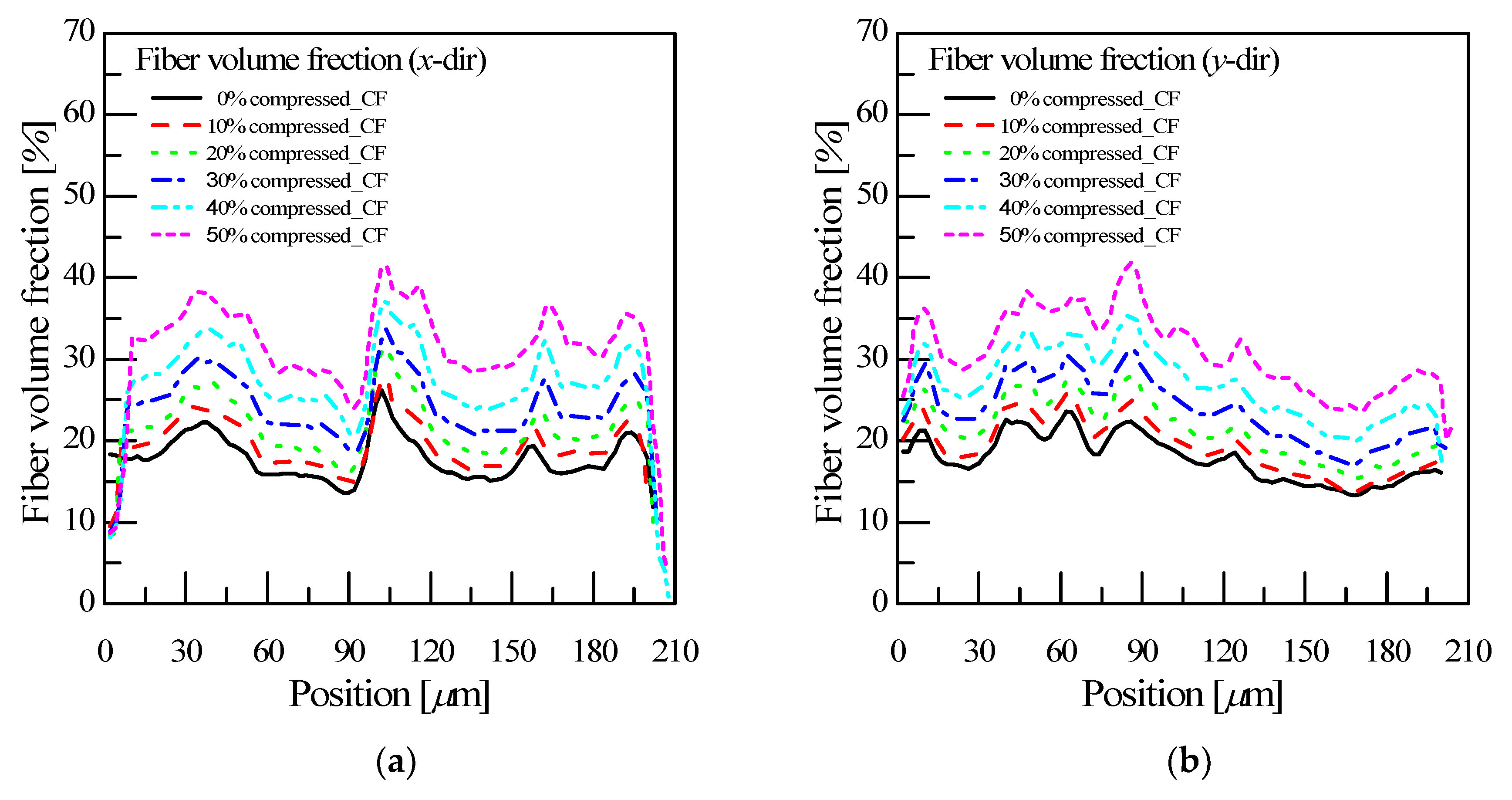
When a fiber network was created with various compression ratios under the above conditions, the carbon fibers were drained out of the unit-cell domain during the compression process. As a result, a procedure was performed to exclude fibers and resin that deviated from the domain area. Figure 2 shows the variation of fiber volume fraction along the x-direction and y-direction according to the GDL compression ratio. There are rapid changes in the fiber content at the two opposite parallel sides, which are the boundaries of the domains, and this is due to the out-of-domain fibers and matrix.
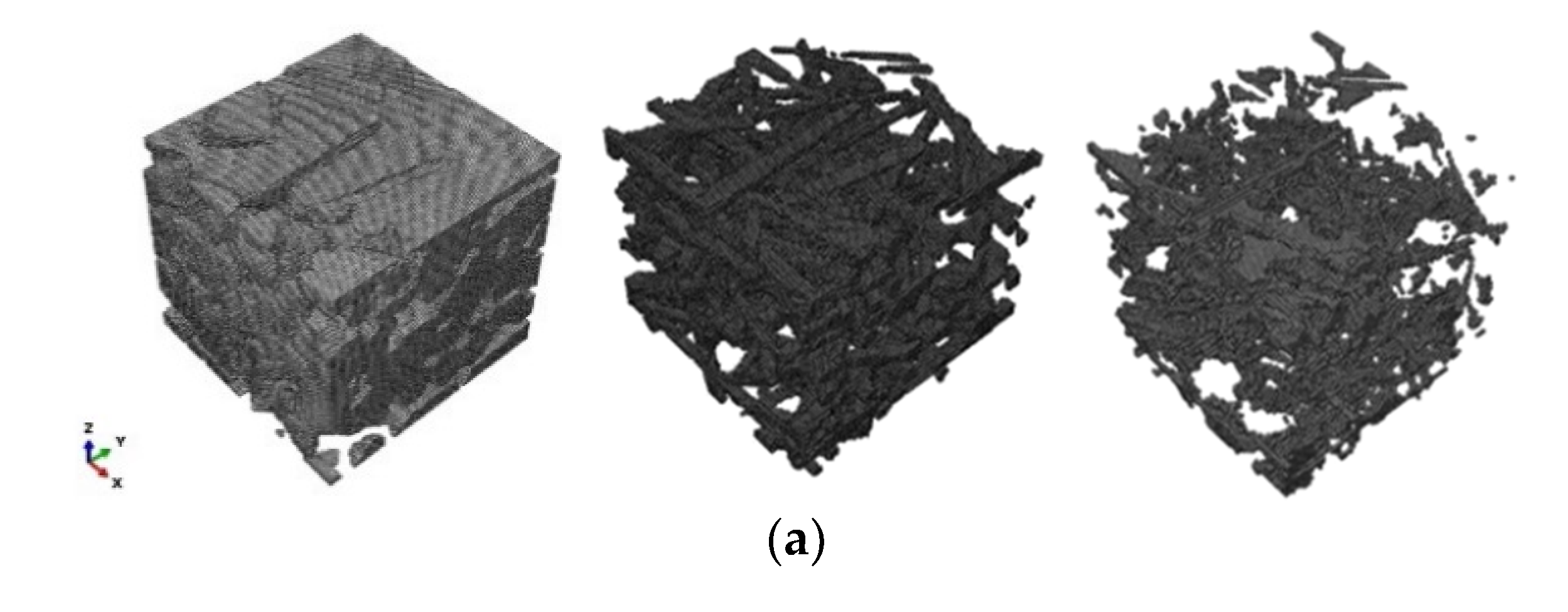
Figure 3 shows the GDL fiber network according to the compression ratio, which allows visual identification of changes in porosity, carbon fiber and epoxy content. Table 2 and Table 3 indicate the results for the overall orientation tensor for carbon fiber as reinforcement, and geometric properties with the compression ratios, respectively. Figure 3 and Table 2 are the input values for calculating the equivalent properties in the commercial program ABAQUS.

3.3. Boundary Conditions in the Finite Element Model

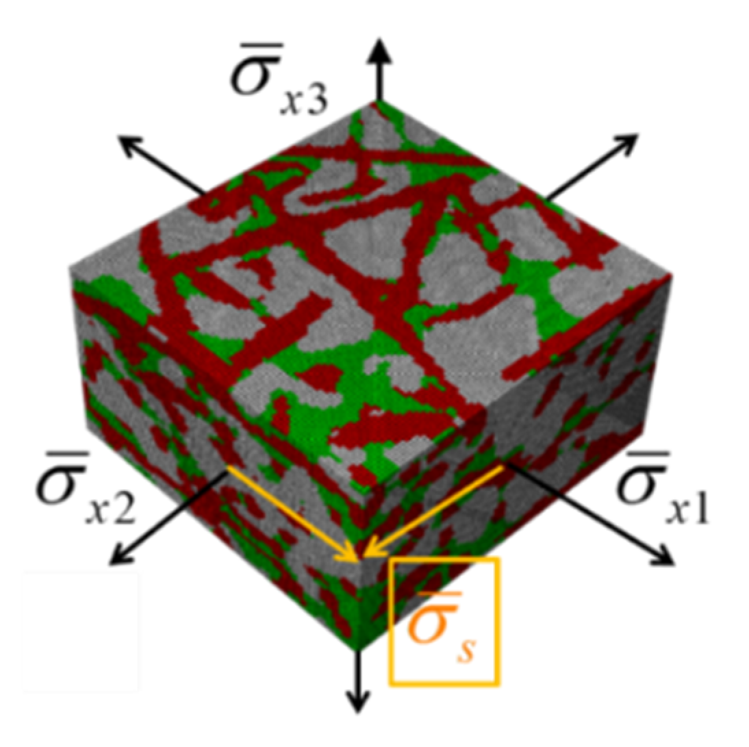
As shown in Figure 4, the homogeneous boundary conditions applied to the surface of a homogeneous object create a uniform field in the commercial software ABAQUS. These boundary conditions are obtained by imposing displacements at the boundary as follows [45,52,53]:
u i ( S ) = ε i j 0 x j
where ε i j are constant strains.
Meshing constitutes a challenge for microstructural simulations of composite materials. To avoid these difficulties with automated meshing, the simulations are usually performed on regular voxel grids.

4. Results and Discussion

4.1. Verification Results for Fourier Series-Based Homogenization Theory

To verify the proposed the Fourier series (FS)-based homogenization theory, the numerical analysis was performed for the unit-cell established in Section 3.1. Here, the fiber volume fraction, phase contrast combination amount and resolution were 13%, ς = 44 and 125, respectively. Muller et al. [44] confirmed that the higher the resolution, the smaller the phase contrast ratio and the smaller the deviation range of the result. For the GDL fiber network of this paper, the phase contrast combination amount satisfies the condition that the reliability is secured with ς = 73.7 and resolution = 100.
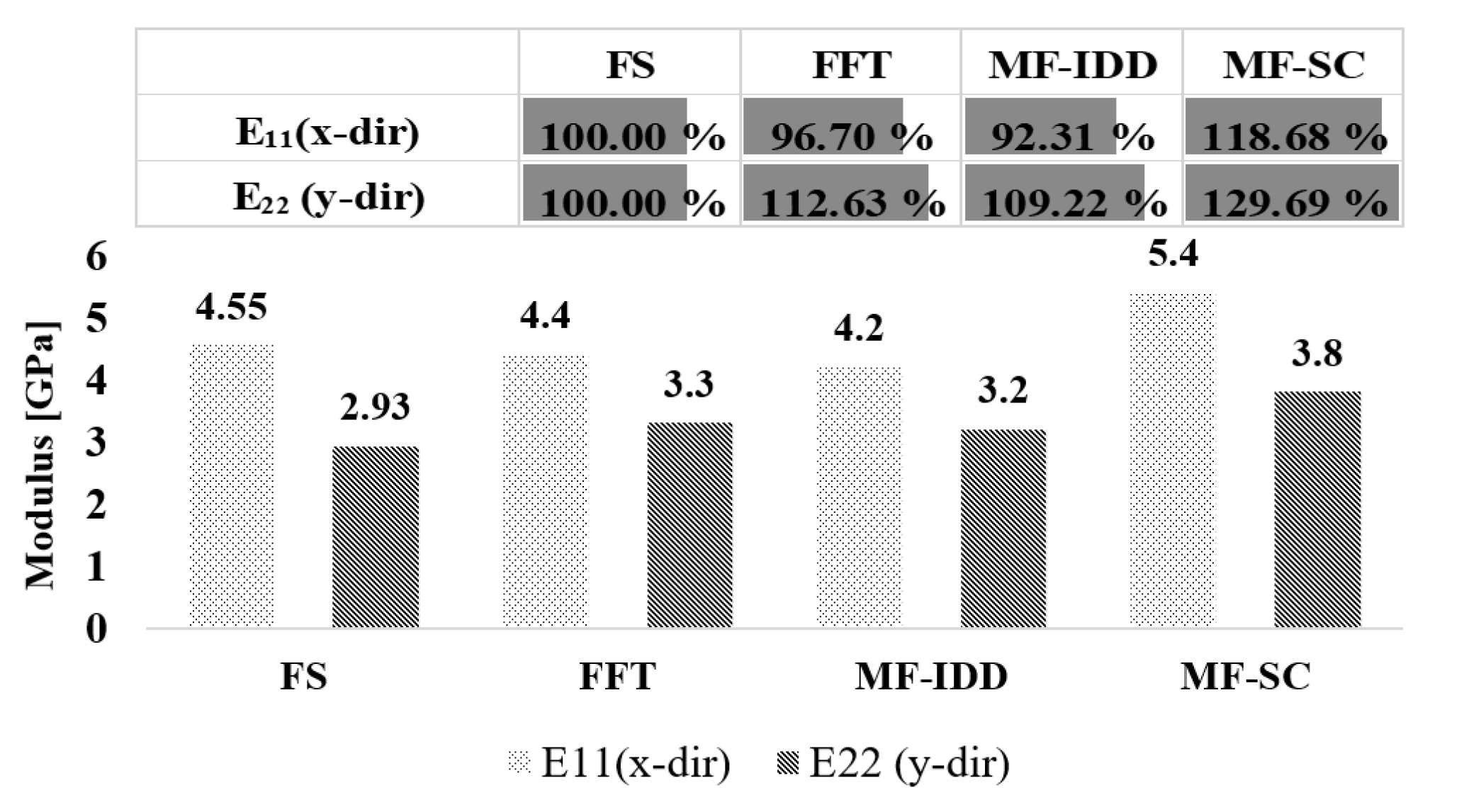
Numerical analysis was performed based on FS theory for the unit-cells using the commercial software ABAQUS. The user run-script was developed using a homogenization technique based on the FS to compute equivalence properties. Figure 5 compares the equivalent properties obtained from the Fourier series-based homogenization method developed in this paper, with the results from the conventional homogenization methods which have been already verified by several studies [44] such as the fast Fourier transformation (FFT), the mean field generalized self-consistent (MF-SC) and mean field interaction direct derivative (MF-IDD). Assuming that the result obtained by the FS-based homogenization theory is 100%, the degree error of the results from the conventional methods can be identified by comparing the referenced results [44] with the longitudinal elastic moduli (E11 and E22). The results of the FS-based homogenization theory are relatively intermediate of the properties obtained from the FFT, MF-IDD and MF-SC theories.

4.2. Evaluation of Equivalent Properties of GDL for Different Compression Ratios

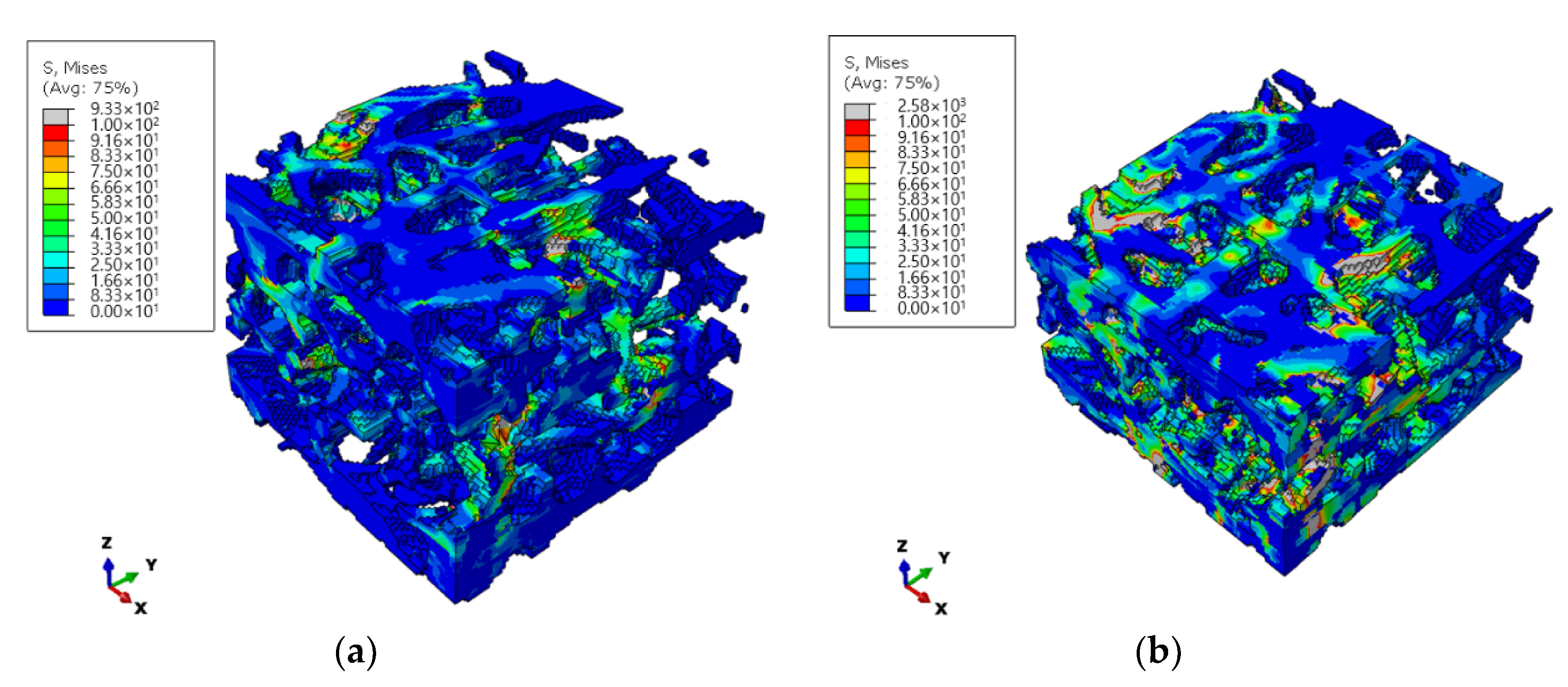
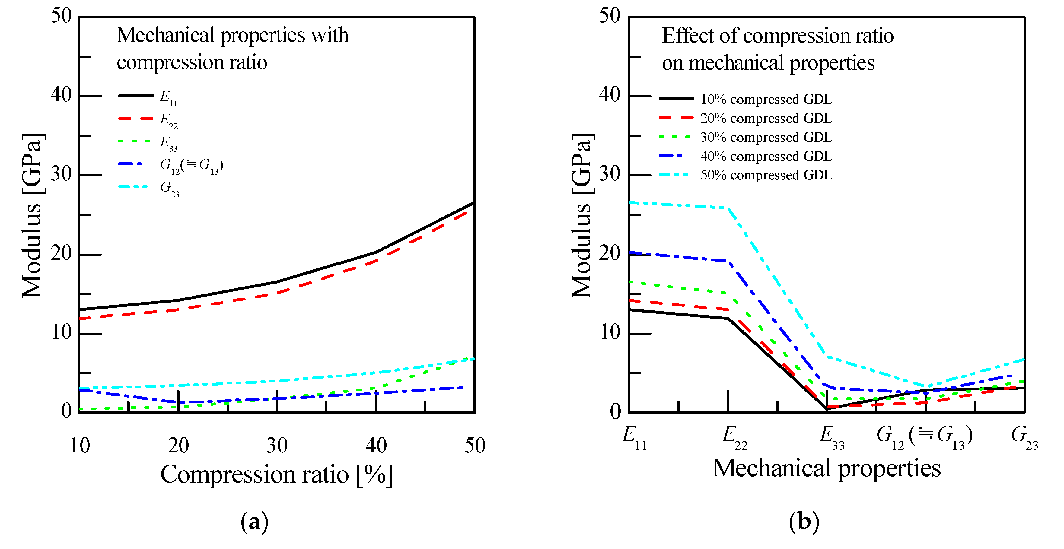
The homogenization analysis for the GDL unit-cell was performed to identify the equivalent mechanical properties with the compression ratios based on FS-based homogenization theory verified in previous section. Figure 6 indicates the stress distributions for the GDL unit-cell at compression ratios of 30% and 50%, respectively, under the compression load of 100 N. In the figure, the 50% compressed GDL shows a denser fiber distribution and much higher stress distribution than the 30% compressed GDL, as expected. As the stress distribution is identified to be affected compression ratios, the effective physical properties are also considered to be influenced by the compression ratios. Figure 7 shows the resulting effective mechanical properties with compression ratios. From Figure 7a, it can be seen that the effective physical properties of the GDL increase in proportion to the compression ratios. The E11 and E22 are increasing rapidly at a compression ratio of 30% or more, and the E33 is remarkably small at a noncompression state but is greatly increased with increasing compression ratio. This is because the FVF of Table 3, which has the greatest effect on the longitudinal elastic modulus, increases sharply at a compression ratio of 30% or more. On the other hand, the shear moduli have different behavior with the compression ratio. Further understating the effect of the compression ratio on the mechanical properties, each mechanical property is summarized with the compression ratios and shown in Figure 7b. In the figure, the longitudinal elastic moduli (E11, E22 and E33) show a rapid increase according to the compression ratio, and the shear moduli have a relatively small effect. From these results, it can be stated that the change of fiber volume fraction according to the compression ratio has a great effect on the longitudinal elastic moduli but relatively little effect on the shear elastic moduli.

5. Conclusions

In this study, we developed a technique using the FS method to predict the effective mechanical properties for discontinuous nonwoven GDLs under compressive loading conditions. The following conclusions were obtained.
  • A user run-script was developed using a homogenization technique based on the Fourier series to compute effective mechanical properties of GDLs with various compress ratios;
  • Among the several homogenization theories, the homogenization theory with the Fourier series method is suitable to predict the effective mechanical properties of GDLs;
  • The change of fiber volume fraction according to the compression ratio has a great effect on the longitudinal elastic moduli but relatively little effect on the shear elastic moduli;
  • The fiber volume fraction increases sharply at the compression ratios of more than 30%, and then the effective mechanical properties and the stress/force behaviors rapidly change.

Author Contributions

Data curation, J.-W.J. and K.-W.K.; software, H.L. and C.-W.C.; writing—review and editing, J.-W.J. All authors have read and agreed to the published version of the manuscript.

Funding

This work was supported by the National Research Foundation of Korea (NRF) grant funded by the Korea government (MSIT) (NRF-2018R1C1B6002221) and Korea Electric Power Corporation (R20XO02-29).

Conflicts of Interest

The authors declare no conflict of interest.

References

  1. Ahn, J.; Park, S.H.; Lee, S.; Noh, Y.; Chang, D. Molten carbonate fuel cell (MCFC)-based hybrid propulsion systems for a liquefied hydrogen tanker. Int. J. Hydrogen Energy 2018, 43, 7525–7537. [Google Scholar] [CrossRef]
  2. Abdalla, A.M.; Hossain, S.; Azad, A.T.; Petra, P.M.I.; Begum, F.; Eriksson, S.G.; Azad, A.K. Nanomaterials for solid oxide fuel cells: A review. Renew. Sustain. Energy Rev. 2018, 82, 353–368. [Google Scholar] [CrossRef]
  3. Huang, Y.L.; Hussain, A.M.; Wachsman, E.D. Nanoscale cathode modification for high performance and stable low-temperature solid oxide fuel cells (SOFCs). Nano Energy 2018, 49, 186–192. [Google Scholar] [CrossRef]
  4. Inal, O.B.; Deniz, C. Assessment of fuel cell types for ships: Based on multi-criteria decision analysis. J. Clean. Prod. 2020, 265, 121734. [Google Scholar] [CrossRef]
  5. Ishikawa, H.; Teramoto, T.; Ueyama, Y.; Sugawara, Y.; Sakiyama, Y.; Kusakabe, M.; Uchida, M. Use of a sub-gasket and soft gas diffusion layer to mitigate mechanical degradation of a hydrocarbon membrane for polymer electrolyte fuel cells in wet-dry cycling. J. Power Sources 2016, 325, 35–41. [Google Scholar] [CrossRef] [Green Version]
  6. Weng, L.C.; Bell, A.T.; Weber, A.Z. Towards membrane-electrode assembly systems for CO2 reduction: A modeling study. Energy Environ. Sci. 2019, 12, 1950–1968. [Google Scholar] [CrossRef] [Green Version]
  7. Laoun, B.; Kasat, H.A.; Ahmad, R.; Kannan, A.M. Gas diffusion layer development using design of experiments for the optimization of a proton exchange membrane fuel cell performance. Energy 2018, 151, 689–695. [Google Scholar] [CrossRef]
  8. Carcadea, E.; Varlam, M.; Ismail, M.; Ingham, D.B.; Marinoiu, A.; Raceanu, M.; Ion-Ebrasu, D. PEM fuel cell performance improvement through numerical optimization of the parameters of the porous layers. Int. J. Hydrogen Energy 2020, 45, 7968–7980. [Google Scholar] [CrossRef]
  9. Jo, A.; Ahn, S.; Oh, K.; Kim, W.; Ju, H. Effects of metal foam properties on flow and water distribution in polymer electrolyte fuel cells (PEFCs). Int. J. Hydrogen Energy 2018, 43, 14034–14046. [Google Scholar] [CrossRef]
  10. Xing, L.; Shi, W.; Su, H.; Xu, Q.; Das, P.K.; Mao, B.; Scott, K. Membrane electrode assemblies for PEM fuel cells: A review of functional graded design and optimization. Energy 2019, 177, 445–464. [Google Scholar] [CrossRef]
  11. Park, J.; Oh, H.; Lee, Y.I.; Min, K.; Lee, E.; Jyoung, J.Y. Effect of the pore size variation in the substrate of the gas diffusion layer on water management and fuel cell performance. Appl. Energy 2016, 171, 200–212. [Google Scholar] [CrossRef]
  12. Kupgan, G.; Liyana-Arachchi, T.P.; Colina, C.M. NLDFT pore size distribution in amorphous microporous materials. Langmuir 2017, 33, 11138–11145. [Google Scholar] [CrossRef] [Green Version]
  13. Nishimura, A.; Sato, Y.; Kamiya, S.; Okado, T.; Yamamoto, K.; Hirota, M.; Hu, E. Impact of thickness of polymer electrolyte membrane and gas diffusion layer on temperature distributions in polymer electrolyte fuel cell operated at temperature around 90 °C. J. Energy Power Eng. 2019, 13, 97–115. [Google Scholar] [CrossRef]
  14. Mahmoudi, A.H.; Ramiar, A.; Esmaili, Q. Effect of inhomogeneous compression of gas diffusion layer on the performance of PEMFC with interdigitated flow field. Energy Convers. Manag. 2016, 110, 78–89. [Google Scholar] [CrossRef]
  15. Ito, H.; Iwamura, T.; Someya, S.; Munakata, T.; Nakano, A.; Heo, Y.; Kitahara, T. Effect of through-plane polytetrafluoroethylene distribution in gas diffusion layers on performance of proton exchange membrane fuel cells. J. Power Sources 2016, 306, 289–299. [Google Scholar] [CrossRef] [Green Version]
  16. Ito, H.; Heo, Y.; Ishida, M.; Nakano, A.; Someya, S.; Munakata, T. Application of a self-supporting microporous layer to gas diffusion layers of proton exchange membrane fuel cells. J. Power Sources 2017, 342, 393–404. [Google Scholar] [CrossRef]
  17. Simon, C.; Hasché, F.; Gasteiger, H.A. Influence of the gas diffusion layer compression on the oxygen transport in PEM fuel cells at high water saturation levels. J. Electrochem. Soc. 2017, 164, F591. [Google Scholar] [CrossRef] [Green Version]
  18. Lee, J.; Chevalier, S.; Banerjee, R.; Antonacci, P.; Ge, N.; Yip, R.; Bazylak, A. Investigating the effects of gas diffusion layer substrate thickness on polymer electrolyte membrane fuel cell performance via synchrotron X-ray radiography. Electrochim. Acta 2017, 236, 161–170. [Google Scholar] [CrossRef]
  19. Kanchan, B.K.; Randive, P.; Pati, S. Numerical investigation of multi-layered porosity in the gas diffusion layer on the performance of a PEM fuel cell. Int. J. Hydrogen Energy 2020, 45, 21836–21847. [Google Scholar] [CrossRef]
  20. Toghyani, S.; Nafchi, F.M.; Afshari, E.; Hasanpour, K.; Baniasadi, E.; Atyabi, S.A. Thermal and electrochemical performance analysis of a proton exchange membrane fuel cell under assembly pressure on gas diffusion layer. Int. J. Hydrogen Energy 2018, 43, 4534–4545. [Google Scholar] [CrossRef]
  21. Jeon, D.H. Effect of channel-rib width on water transport behavior in gas diffusion layer of polymer electrolyte membrane fuel cells. J. Power Sources 2019, 423, 280–289. [Google Scholar] [CrossRef]
  22. Zhou, X.; Niu, Z.; Li, Y.; Sun, X.; Du, Q.; Xuan, J.; Jiao, K. Investigation of two-phase flow in the compressed gas diffusion layer microstructures. Int. J. Hydrogen Energy 2019, 44, 26498–26516. [Google Scholar] [CrossRef]
  23. Aldakheel, F.; Ismail, M.S.; Hughes, K.J.; Ingham, D.B.; Ma, L.; Pourkashanian, M.; Mith, R. Gas permeability, wettability and morphology of gas diffusion layers before and after performing a realistic ex-situ compression test. Renew. Energy 2020, 151, 1082–1091. [Google Scholar] [CrossRef]
  24. Cheema, T.A.; Kim, G.M.; Lee, C.Y.; Kwak, M.K.; Kim, H.B.; Park, C.W. Effects of composite porous gas-diffusion layers on performance of proton exchange membrane fuel cell. Int. J. Precis. Eng. Manuf. Green Technol. 2014, 1, 305–312. [Google Scholar] [CrossRef] [Green Version]
  25. Hwang, Y.S.; Choi, H.; Cho, G.; Lee, Y.; Cha, S.W. Effect of compression thickness on performance of gas diffusion layer of direct methanol fuel cells. Int. J. Precis. Eng. Manuf. Green Technol. 2014, 1, 215–221. [Google Scholar] [CrossRef]
  26. Jeong, H.S.; Kim, J.I.; Lee, S.H.; Lim, C.H.; Ahn, B.K.; Kim, C.J. Analysis of Mass Transport in PEMFC GDL. Trans. Korean Soc. Mech. Eng. B 2012, 36, 979–988. [Google Scholar] [CrossRef]
  27. Chippar, P.O.K.; Kang, K.; Ju, H. A numerical investigation of the effects of GDL compression and intrusion in polymer electrolyte fuel cells (PEFCs). Int. J. Hydrogen Energy 2012, 37, 6326–6338. [Google Scholar] [CrossRef]
  28. Higgins, D.; Hahn, C.; Xiang, C.; Jaramillo, T.F.; Weber, A.Z. Gas-diffusion electrodes for carbon dioxide reduction: A new paradigm. ACS Energy Lett. 2018, 4, 317–324. [Google Scholar] [CrossRef] [Green Version]
  29. Mahnken, R.; Ju, X. Goal-oriented adaptivity based on a model hierarchy of mean-field and full-field homogenization methods in linear elasticity. Int. J. Numer. Methods Eng. 2019, 2, 277–307. [Google Scholar] [CrossRef] [Green Version]
  30. Voigt, W. Ueber die Beziehung zwischen den beiden Elasticitätsconstanten isotroper Körper. Ann. Physic 1889, 274, 573–587. [Google Scholar] [CrossRef] [Green Version]
  31. Hashin, Z.; Shtrikman, S. On some variational principles in anisotropic and nonhomogeneous elasticity. J. Mech. Phys. Solids 1962, 10, 335–342. [Google Scholar] [CrossRef]
  32. Willis, J.R. Bounds and self-consistent estimates for the overall properties of anisotropic composites. J. Mech. Phys. Solids 1977, 25, 185–202. [Google Scholar] [CrossRef]
  33. Mori, T.; Tanaka, K. Average stress in matrix and average elastic energy of materials with misfitting inclusions. Acta Metall. 1973, 21, 571–574. [Google Scholar] [CrossRef]
  34. Christensen, R.M.; Lo, K.H. Solutions for effective shear properties in three phase sphere and cylinder models. J. Mech. Phys. Solids 1979, 27, 315–330. [Google Scholar] [CrossRef]
  35. Eshelby, J.D. The Determination of the Elastic Field of an Ellipsoidal Inclusion, and Related Problems. In Proceedings of the Royal Society of London Series A, Mathematical and Physical Sciences, London, UK, 20 August 1957; Volume 241, pp. 376–396. [Google Scholar]
  36. Doghri, I.; Friebel, C. Effective elasto-plastic properties of inclusion-reinforced composites. Study of shape, orientation and cyclic response. Mech. Mater. 2005, 37, 45–68. [Google Scholar] [CrossRef]
  37. Doghri, I.; Tinel, L. Micromechanics of inelastic composites with misaligned inclusions: Numerical treatment of orientation. Comput. Methods Appl. Mech. Eng. 2006, 195, 1387–1406. [Google Scholar] [CrossRef]
  38. Tian, W.; Qi, L.; Chao, X.; Liang, J.; Fu, M.W. A new interpolative homogenization model for evaluation of the effective elasto-plastic responses of two-phase composites. Compos. Struct. 2019, 210, 810–821. [Google Scholar] [CrossRef]
  39. Guedes, J.; Kikuchi, N. Preprocessing and postprocessing for materials based on the homogenization method with adaptive finite element methods. Comput. Methods Appl. Mech. Eng. 1990, 83, 143–198. [Google Scholar] [CrossRef] [Green Version]
  40. Moulinec, H.; Suquet, P. A FFT-based numerical method for computing the mechanical properties of composites from images of their microstructures. In IUTAM Symposium on Microstructure-Property Interactions in Composite Materials; Springer: Dordrecht, The Netherlands, 1995; pp. 235–246. [Google Scholar]
  41. Ghosh, S.; Lee, K.; Moorthy, S. Multiple scale analysis of heterogeneous elastic structures using homogenization theory and voronoi cell finite element method. Int. J. Solids Struct. 1995, 32, 27–62. [Google Scholar] [CrossRef]
  42. Miehe, C.; Schotte, J.; Lambrecht, M. Homogenization of inelastic solid materials at finite strains based on incremental minimization principles. Application to the texture analysis of polycrystals. J. Mech. Phys. Solids 2002, 50, 2123–2167. [Google Scholar] [CrossRef]
  43. Esbati, A.H.; Irani, S. Mechanical properties and fracture analysis of functionalized carbon nanotube embedded by polymer matrix. Aerosp. Sci. Technol. 2016, 55, 120–130. [Google Scholar] [CrossRef]
  44. Müller, V.; Kabelm, M.; Andrä, H.; Böhlke, T. Homogenization of linear elastic properties of short-fiber reinforced composites—A comparison of mean field and voxel-based methods. Int. J. Solids Struct. 2015, 67, 56–70. [Google Scholar] [CrossRef]
  45. Aboudi, J.; Arnold, S.M.; Bednarcyk, B.A. Chapter 3—Fundamentals of the Mechanics of Multiphase Materials. In Micromechanics of Composite Materials; Butterworth-Heinemann: Oxford, UK, 2013; pp. 87–145. [Google Scholar]
  46. Luciano, R.; Barbero, E.J. Formulas for the stiffness of composites with periodic microstructure. Int. J. Solids Struct. 1994, 31, 2933–2944. [Google Scholar] [CrossRef]
  47. Nemat-Nasser, S.; Iwakuma, T.; Hejazi, M. On composites with periodic structure. Mech. Mater. 1982, 1, 239–267. [Google Scholar] [CrossRef]
  48. Lee, H. Multiscale Evaluation of Equivalent Mechanical Properties of Nonwoven Carbon-Fiber Fabric Composites; Chonbuk National University: Jeonju, Korea, 2017. [Google Scholar]
  49. Lee, H.; Choi, C.W.; Jin, J.W.; Huh, M.; Lee, S.; Kang, K.W. Homogenization-based multiscale analysis for equivalent mechanical properties of nonwoven carbon-fiber fabric composites. J. Mech. Sci. Technol. 2019, 33, 4761–4770. [Google Scholar] [CrossRef]
  50. Advani, S. Prediction of Fiber Orientation during Processing of Short Fiber Composites; ProQuest Dissertations Publishing: Ann Arbor, MI, USA, 1987. [Google Scholar]
  51. Nemat-Nasser, S.; Hori, M. Micromechanics: Overall Properties of Heterogeneous Materials; Elsevier: Amsterdam, The Netherlands, 2013. [Google Scholar]
  52. Barbero, E.J. Finite Element Analysis of Composite Materials Using Abaqus TM; CRC Press: Boca Raton, FL, USA, 2013. [Google Scholar]
  53. Jeong, J.Y.; Ha, S.K. Analysis of Micromechanical Behavior for Fiber-Reinforced Composites. Trans. Korean Soc. Mech. Eng. 2004, A28, 1435–1450. [Google Scholar] [CrossRef]
  54. Götz, T.; Klar, A.; Marheineke, N.; Wegener, R. A Stochastic Model and Associated Fokker-Planck Equation for the Fiber Lay-down Process in Nonwoven Production Processes. SIAM J. Appl. Math. 2007, 67, 1704–1717. [Google Scholar] [CrossRef]
  55. Grothaus, M.; Klar, A. Ergodicity and Rate of Convergence for a Nonsectorial Fiber Lay-Down Process. SIAM J. Math. Anal. 2008, 40, 968–983. [Google Scholar] [CrossRef]
  56. Holzer, L.; Pecho, O.; Schumacher, J.; Marmet, P.; Stenzel, O.; Büchi, F.N.; Münch, B. Microstructure-property relationships in a gas diffusion layer (GDL) for Polymer Electrolyte Fuel Cells, Part I: Effect of compression and anisotropy of dry GDL. Electrochim. Acta 2017, 227, 419–434. [Google Scholar] [CrossRef]
  57. Glatt, E.; Huber, F.; Enzmann, F.; Schaefer, T.; Wiegmann, A. GeoDict; The Digital Material Laboratory, Math2Market GmbH: Kaiserslautern, Germany. 2020. Available online: http://www.geodict.com (accessed on 21 October 2020).
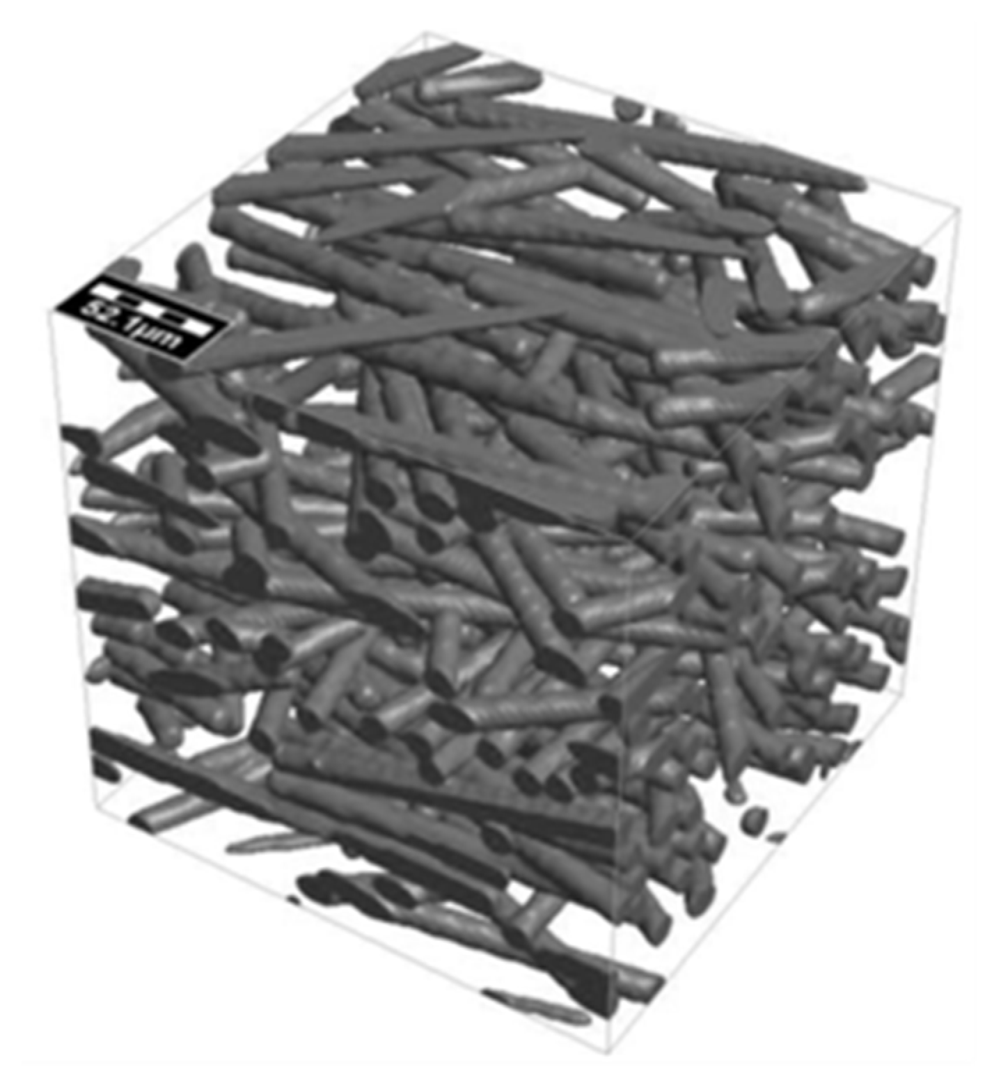
Figure 1. Generated fiber network of unit-cell.
Applsci 10 07407 g001
Figure 2. Generated fiber volume fraction for different compression ratios: (a) Fiber volume fraction (x-dir); (b) fiber volume fraction (y-dir).
Applsci 10 07407 g002
Figure 3. Generated fiber network of unit-cell: (a) 10% compressed gas diffusion layer (GDL) model; (b) 20% compressed GDL model; (c) 30% compressed GDL model; (d) 40% compressed GDL model; (e) 50% compressed GDL model.
Applsci 10 07407 g003aApplsci 10 07407 g003b
Figure 4. Boundary conditions for calculating components.
Applsci 10 07407 g004
Figure 5. Comparison of prediction results for homogenization theory.
Applsci 10 07407 g005
Figure 6. Analysis image of GDL structure at 30% and 50% compression: (a) 30% compressed GDL; (b) 50% compressed GDL.
Applsci 10 07407 g006
Figure 7. Analysis results according to compression ratios: (a) Mechanical properties with compression ratio; (b) effect of compression ratio on mechanical properties.
Applsci 10 07407 g007
Table 1. Components of orientation tensors used for the generation of microstructures for verification of Fourier series.
Orientation Tensor123
10.61--
2-0.36-
3--0.03
Table 2. Components of orientation tensors used for the generation of the model microstructures
Orientation Tensor123
Original GDL model10.464--
2-0.464-
3--0.072
10% compressed GDL model10.464--
2-0.467-
3--0.069
20% compressed GDL model10.461--
2-0.471-
3--0.068
30% compressed GDL model10.459--
2-0.461-
3--0.080
40% compressed GDL model10.454--
2-0.454-
3--0.092
50% compressed GDL model10.448--
2-0.451-
3--0.101
Table 3. Components of fiber volume fraction for the generation of the model microstructures.
Original10%20%30%40%50%
Porosity70.1670.05
(∇0.11)
65.85
(∇4.2)
61.43
(∇4.42)
55.59
(∇5.84)
47.74
(∇7.85)
Fiber volume fraction17.8919.79
(∆1.9)
22.06
(∆2.27)
24.94
(∆2.88)
29.14
(∆4.2)
35.04
(∆5.9)
Resin volume fraction11.9510.16
(∇1.79)
12.09
(∆0.17)
13.63
(∆1.68)
15.26
(∆3.31)
17.22
(∆5.27)
Publisher’s Note: MDPI stays neutral with regard to jurisdictional claims in published maps and institutional affiliations.