Article

Microstructure and Properties of AA6061/SiCp Composites Sintered under Ultra High-Pressure

1
School of Materials Science and Engineering, Henan Polytechnic University, Jiaozuo 454000, China
2
Faculty of Engineering, China University of Petroleum-Beijing at Karamay, Karamay 834000, China
*
Authors to whom correspondence should be addressed.
These authors contributed equally to this work and should be considered co-first authors.
Appl. Sci. 2020, 10(20), 7363; https://doi.org/10.3390/app10207363
Submission received: 3 September 2020 / Revised: 8 October 2020 / Accepted: 16 October 2020 / Published: 21 October 2020

Abstract

:
Ultra high-pressure sintering (UHPS) was used to prepare AA6061/SiCp composites with different contents and the effect of sintering temperatures on microstructure and mechanical properties was investigated in this study. The results showed that a uniform distribution of nano-SiC particles (N-SiCp) is obtained by the UHPS method. With the increase in N-SiCp contents, the higher hardness and better wear resistance could be inspected. The interfacial reactions and Al4C3 phase appeared above 550 °C. The relative density of composites first increased and then decreased; with the temperature raising it reached 99.58% at 600 °C. The hardness and wear property showed the same trend with the hardness reaching 52 HRA and wear rate being 1.0 × 10⁻⁶ g/m at 600 °C. Besides, the wear mechanism of the composites is mainly composed of abrasive wear and adhesive wear.

1. Introduction

Al matrix composites reinforced by micron-sized particles can significantly improve the properties of materials, such as the hardness, wear-resistance, etc. [1,2,3,4]. However, the large size particles in composite materials may contribute to the appearance of holes around the reinforcement during the preparing process and will break or crack during service, reducing the mechanical properties of the composite. Thus N-SiCp is increasingly used as the reinforcement for composites. Commercial N-SiCp is mostly with irregular shapes, and hence, cracks occur at the sharp corners of the SiCp during the sintering process or service due to stress concentration. However, the N-SiCp prepared by high-energy ball milling is approximately spherical, which can significantly avoid the stress concentration and reduce the generation or propagation of cracks, resulting in the enhancement of the properties of composites. Although N-SiCp can improve the strength of the composite without reducing its plasticity in the related research [2,3,4] on Al matrix composites reinforced by N-SiCp, there are still some problems in the research of composites reinforced by nanoparticles due to the large specific surface area, easy agglomeration, and the low volume fraction of N-SiCp. Besides, the reinforcement particles are inclined to agglomerate and are not easy to sinter for the composite with the large volume fraction [5,6,7,8]. Chao [8] pointed out that the smaller SiCp represented the larger interface area between SiC and matrix in composite materials is, indicating an increased yield strength and tensile strength. Liu [9,10] pointed out that N-SiCp could make the yield strength and tensile strength of composites reach up to 102.5 and 175.0 MPa, respectively, leading to an augment of 50% and 30% than that of matrix alloy. Gao [11] pointed out that the grain size of the Al matrix composites reinforced by single N-SiCp could be significantly refined, showing an improved hardness and wear resistance. Zhang [12] prepared Al matrix composites reinforced by micron SiCp and N-SiCp through the stirring casting method. It was discovered that the nanoparticles can significantly improve the tensile strength and yield strength of the composites. Omyma et al. [13] also studied the hot-pressed sintered Al matrix composites reinforced by N-SiCp. The results showed that the hardness and compressive strength of composites reinforced by N-SiCp were higher than that reinforced by micro-SiC at the same volume fraction. Besides, the grain refinement effect of N-SiCp is significantly better than that of micron SiC.
In summary, researchers have gradually studied the effect of particle size on Al matrix composites from micron to single nanometer [14,15,16]. During the stirring casting process, matrix and reinforcement were mixed through mechanical stirring or magnetic stirring, followed by casting, which makes the SiC more easily agglomerated because of the large specific surface energy of the N-SiCp and the poor wettability between the reinforcement and matrix [17]. Although powder metallurgy combined with ball mill dispersion can reduce the agglomeration phenomenon, the sample with a low density and poor bonding is still prone to generating cracks. There are some certain disadvantages for the preparation methods with the low pressure in previous studies about Al/micro-SiC composites—for example, low density, low strength, shrinkage, and porosity due to the insufficient pressure [14,16]. Therefore, an effective preparation method is particularly important and in urgent need. UHPS, which is characterized by ultra-high-pressure during sintering, has received considerable attention over the past few years because it could solve the problem of the defects produced during conventional powder metallurgy techniques [18]. It was reported [19] that UHPS not only could improve the relative density of composites, but also delay the melting point, which could effectively inhibit the interface reaction. In this study, AA6061/N-SiCp composites were effectively prepared by UHPS above 1 GPa combined with ball milling (N-SiCp+AA6061 pre-dispersion). The effects of the volume fraction of N-SiCp and sintering temperature on the microstructure and mechanical properties of AA6061/N-SiCp composites were analyzed, aiming at the good sintering property.

2. Materials and Experiments

AA6061 alloy powders with an average size of 40~53 μm prepared by JW-25 vacuum metal atomization furnace (Chenhua Science Technology Corp., Ltd., Shanghai, China) were used as matrix material. The measured density and the purity are 2.65 g/cm3 and 99.8%, respectively, and have the color of silver gray, as shown in Figure 1. The N-SiCp, with an average size of 50 nm, the density of 3.227 g/cm3, gray-green color, ellipsoidal shape, purity of 99.9% and the specific surface area of 60 m2/g, is depicted in Figure 2a. The N-SiCp were used as reinforcement and provided by Yaotian New Material Technology Co. Ltd. in Shanghai, China. The chemical compositions of the AA6061 are listed in Table 1. N-SiCp weighed in 1, 3, 5, 10, and 15 vol.% were premixed with AA6061 alloy powder in a mortar and then milled into a high-speed vibrating ball mill (NanDa Instrument Plant, Nanjing, China). The mixing time and speed is 2 h, 300 r/min, respectively. The mixed powders are shown in Figure 2b. To make N-SiCp distribute partly on the surface of the Al particles, the Al particles and the N-SiCp were mixed in a mortar according to the patent CN201210103182.6. The surface energy of the nanoparticles is high, and the coating layer improves the wettability of the material, hence it reduces the agglomeration of the SiC particles.
The 6MK-3WY-60 six-face pressing machine was used as the sintering equipment. The powder is pre-compressed and then filled into the pyrophyllite block for sintering at 4.5 GPa, which is selected according to the experimental data, for 40 min and at 450, 550, 600, and 650 °C, respectively. The pressure was produced by a pressure cylinder, which is connected to a hinge. It uses oil pressure in the pipeline to generate high pressure, which is adjusted by the cross-sectional area. The pressure could be calculated according to Equation (1). P1, P, S1, S, stands for the pressure generated by a pressure cylinder, the pressure applied to the sample, the cross-sectional area of the hammer, the area contacted between the sample, and the hammer, respectively. An optical microscope (OM, Olympus GX-51, Tokyo, Japan) and a field emission scanning electron microscope (SEM, Merlin Compact, Carl Zeiss NTS GmbH, Jena, Germany) were used for microstructure characterization of the polished specimens. An X-ray diffractometer (XRD, SmartLab, Rigaku Corporation, Tokyo, Japan) was used for phase analysis using CuKα radiation in the step scan mode and with the scanning speed of 10°/min. The interface microstructure was characterized using a high-resolution transmission electron microscope (TEM, JEM-2100, JEOL Ltd., Tokyo, Japan). The density was measured by the Archimedes method using the density tester (ED-300C, TecFront Electronics Corp., Shanghai, China). The hardness was measured by a Rockwell hardness tester (HBE-300, Wobot Measuring Instruments Co., Ltd, Shanghai, China), under the load of 50 Kgf for 10 s. The wear tests were conducted by a wear tester (M-2000, Hongda Testing Instrument Co. Ltd., Jinan, China). Every test was repeated three times to check the reproducibility and the reliability of the results.
P = P1S1/S

3. Results and Discussion

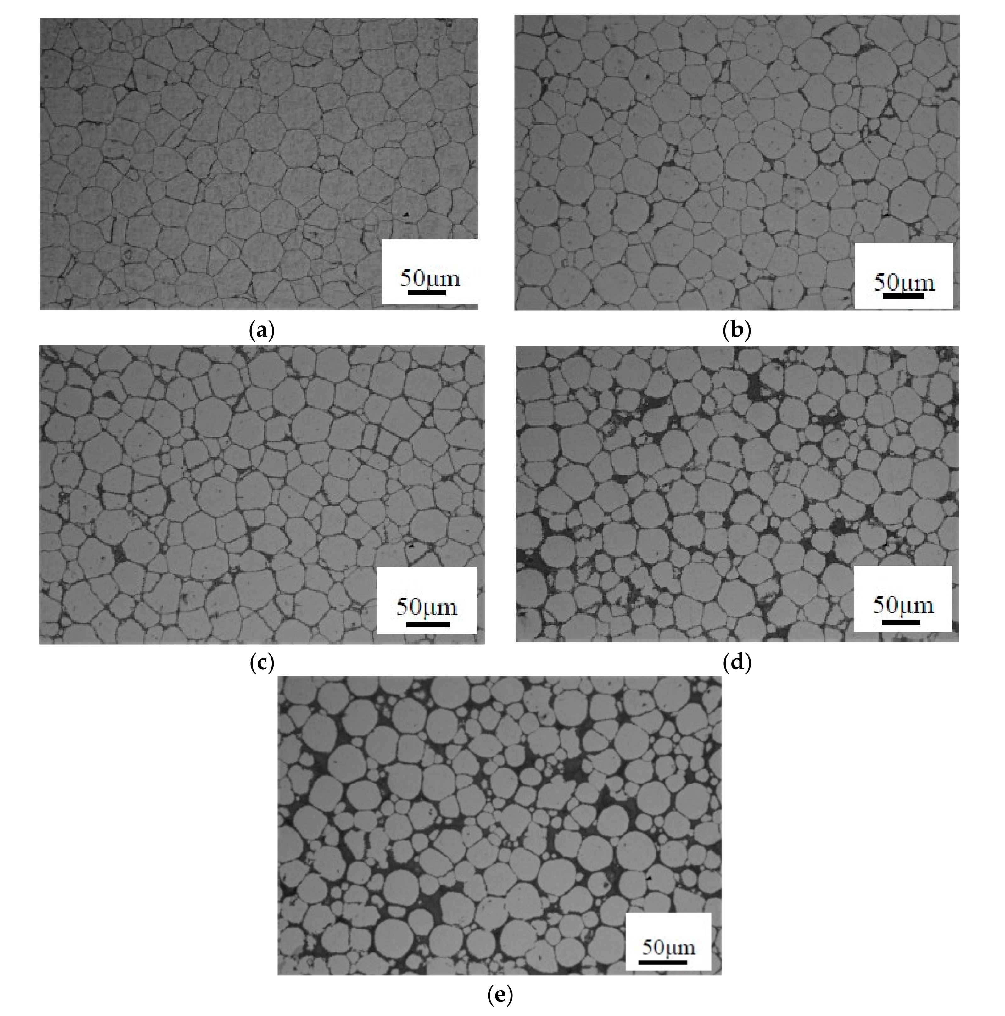
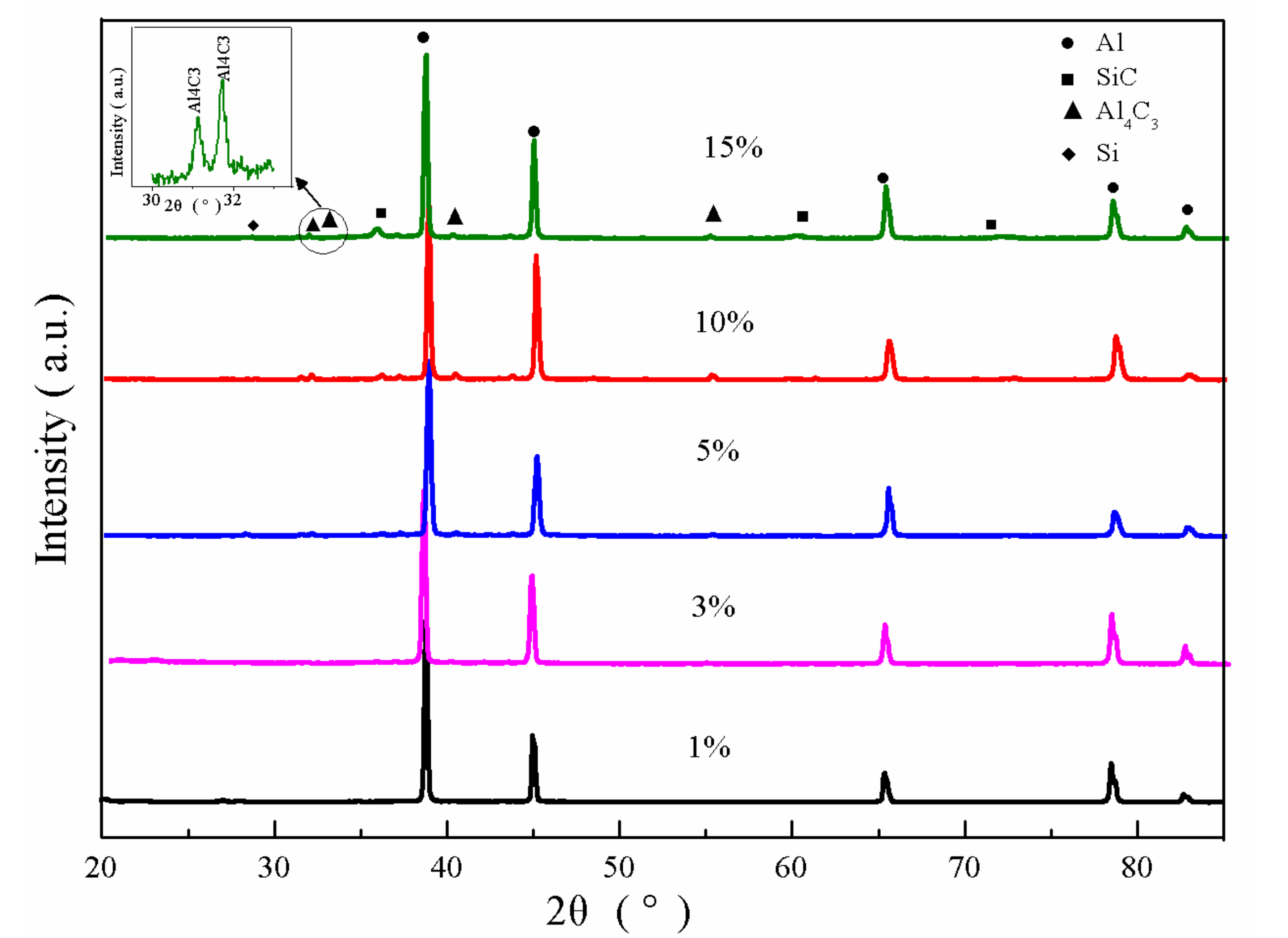
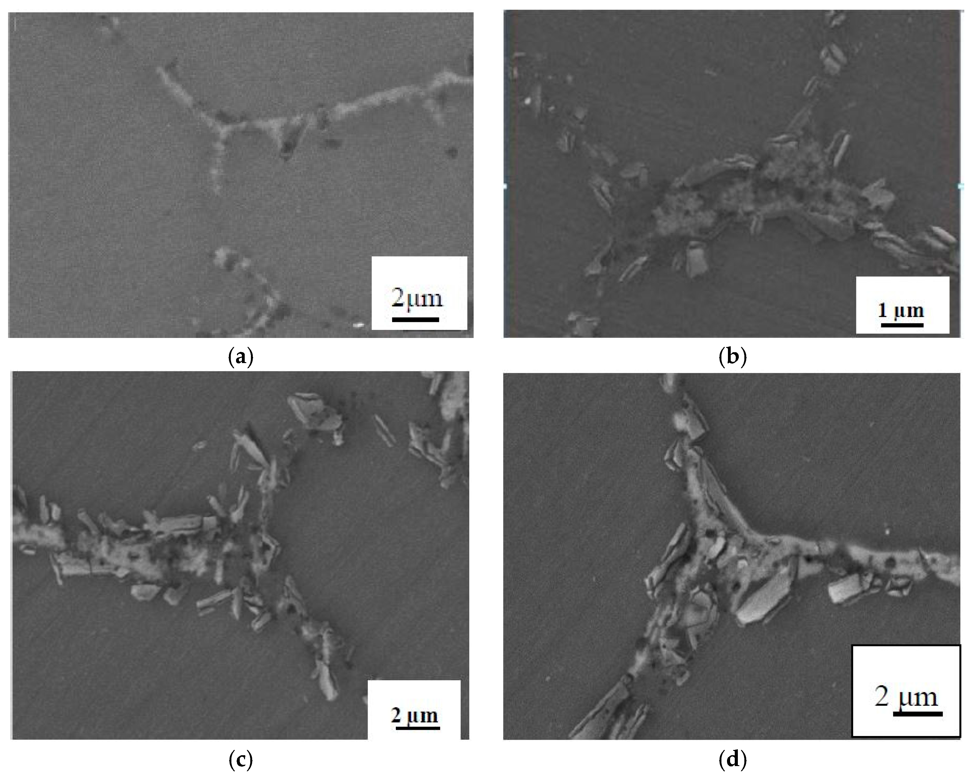
3.1. Effect of the Volume Fractions of N-SiCp on Microstructure and Interface

Figure 3 shows the microstructures of the composites with 1, 3, 10, 15 vol.% N-SiCp sintered at 550 °C under the compacting pressure of 4.5 GP. As shown in Figure 3a,b, Al particles without the agglomerations are uniformly coated with a small layer of the N-SiCp. There are uniform grains with a small difference and smooth grain boundaries. The particles change from a hexagon shape in Figure 3a–d to more circular shapes in Figure 3e at 4.5 GPa. Increasing the volume fraction of the N-SiCp, agglomeration appears at the boundary of the matrix in Figure 3c,d and the roundness of the Al particles increases gradually from an irregular polygon to a circular shape, as shown in Figure 3e. During the process of UHPS, the Al particle is pressed and deformed with each other. As the volume fraction of the N-SiCp increases, the N-SiCp particles surrounded by the Al particles begin to withstand the certain sintering pressure, resulting in the Al particles retaining a good roundness [20]. Besides, as the content of the N-SiCp continues to rise, the particle becomes uneven and increasingly small. During the sintering process, the pores between the particles will diffuse and migrate to the boundary of the matrix, and the small pores merge into the large pores, which make the pores disappear, and the volume of the Al particles becomes smaller.
Figure 4 presents a high-magnification microstructure of AA6061/N-SiCp sintered at 4.5 GPa and 550 °C with different contents of N-SiCp particles. As shown in Figure 4a for AA6061/3 vol.% N-SiCp, N-SiCp lined at the grain boundary of Al particles. What is more, the discontinuous short rod phase (off-white color) appears at the boundaries of Al particles in Figure 4c. The EDS point of Area 1 in Figure 4c is analyzed for the phase, as shown in Figure 5a. The elemental content of this point was obtained from the EDS point analysis. Based on the elemental content, the bulk composition could be judged roughly in the first step. The main elements are Al and O, and the C element is relatively low, which was obtained from Figure 5a. Depending on the element content, it can be judged that the bulk phase is Al4C3 or Al2O3. The line scan analysis of Area 2 in Figure 4d is shown in Figure 5b. The C element and the O element is relatively stable throughout the whole scanning distance. Al content begins to reduce at the intersection of SiC and Al when scanning distance is about 6 μm. In comparison, Si content presents an increasing trend. The lowest Al content could be found at approximately 7.5 μm distance and the infiltration zone lasts for 1 μm. Similarly, an elemental interpretation zone of about 0.8 μm appears on the other side at 13 μm. The interdiffusion of the elements promotes the reaction between the elements in the interface region, causing the formation of compounds. However, the bonding strength increases when the amount of Al4C3 is small. When the amount of Al4C3 reaches a critical value, the interface will be damaged. The influence of the specific product content on the properties of the composite material has not been specifically reported before.
To further determine the composition of the phase, X-ray diffraction was used to examine the constituents of the AA6061/N-SiCp composites with different volume fractions of N-SiCp, as shown in Figure 6. With the increase in SiCp content, the peak intensity of SiC gradually increases at 32°. For AA6061/5 vol.% N-SiCp, the two main peaks of the Al4C3 phase are detected at 2θ of 31°~32° while the peak is not detected for the sample with 1 or 3 vol.% N-SiCp. Combined with the SEM micrograph of AA6061/3 vol.% N-SiCp, a short rod-like phase appears at a certain position. The larger volume fraction of N-SiCp content is, the more N-SiCp around the Al particles, and the larger the interface surface exists between N-SiCp and Al particles. Moreover, the probability of reaction will increase, resulting in more product.
Figure 7a shows the TEM micrographs of AA6061/1 vol.% N-SiCp. Figure 7b shows the high-resolution microstructure of the interface in Figure 7a. The dark gray ellipsoidal particles in Figure 7a are N-SiC particles with a size of 50 nm, and the white edge is the Al matrix. The interface of the AA6061/1 vol.% N-SiCp is clean and combined tightly and continuously. Figure 7c shows an inverse Fourier transform diagram of the high-resolution map of the C region in Figure 8b. There are many dislocations near the N-SiCp interface. There usually exist thermal misfit dislocations at the interface due to the difference in the thermal expansion coefficient during sintering and cooling. Miller and Humphrey [21] derived the formula of the dislocation density increment for the ideal cubic shape reinforcement particle composite:
Δ ρ = 12 Δ α Δ T V P / B D
where Δα and ΔT are the difference in thermal expansion coefficient between the reinforcement and the matrix and the temperature difference between the sintering temperature and room temperature, respectively. B means Berner vector, which could be determined by the Berner loop of the dislocation, the Berner vector of the dislocation loop, or half-dislocation loop, which is relatively complicated [22]. D and Vp are the average sizes of the reinforcement particles and the volume fraction of the reinforcement, respectively.
Equation (2) illustrates that the dislocation density is related to the thermal expansion coefficient of the reinforcement material and the matrix material, the sintering temperature, the size and volume fraction of the reinforcement particles. The smaller the reinforcement is, the larger dislocation densities that can be obtained. Furthermore, increased dislocation density can also improve the strength of the material.

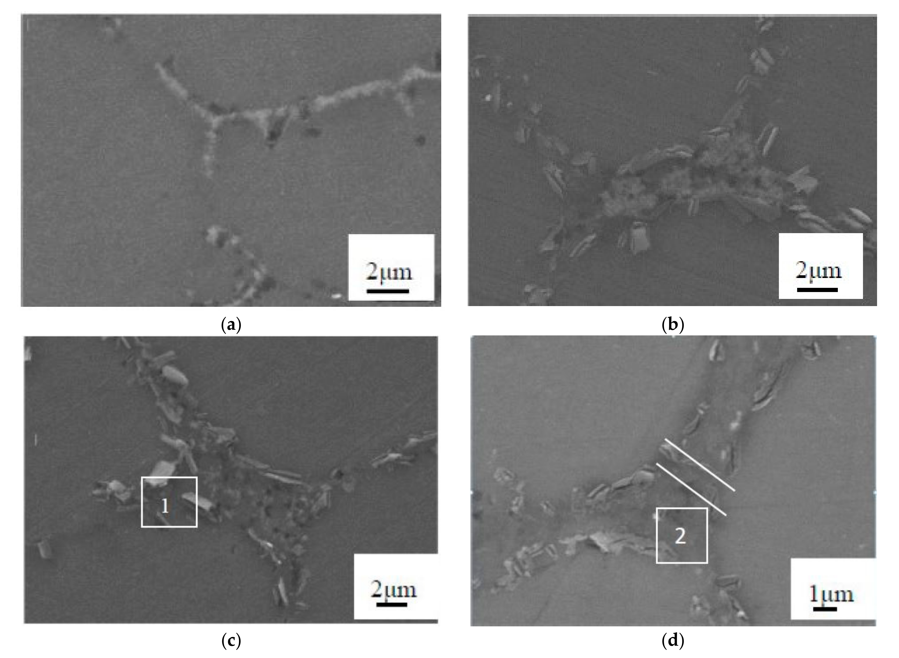
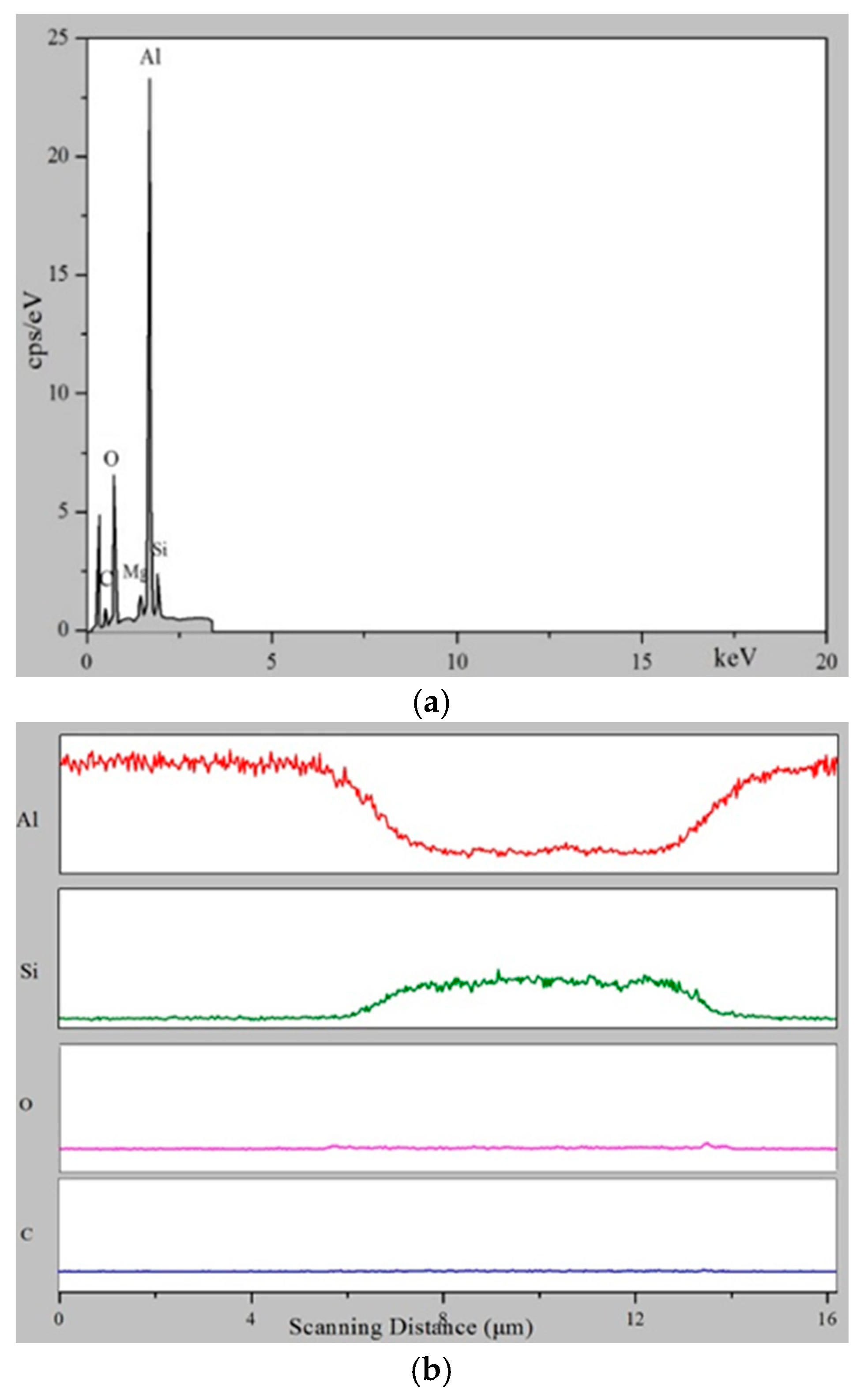
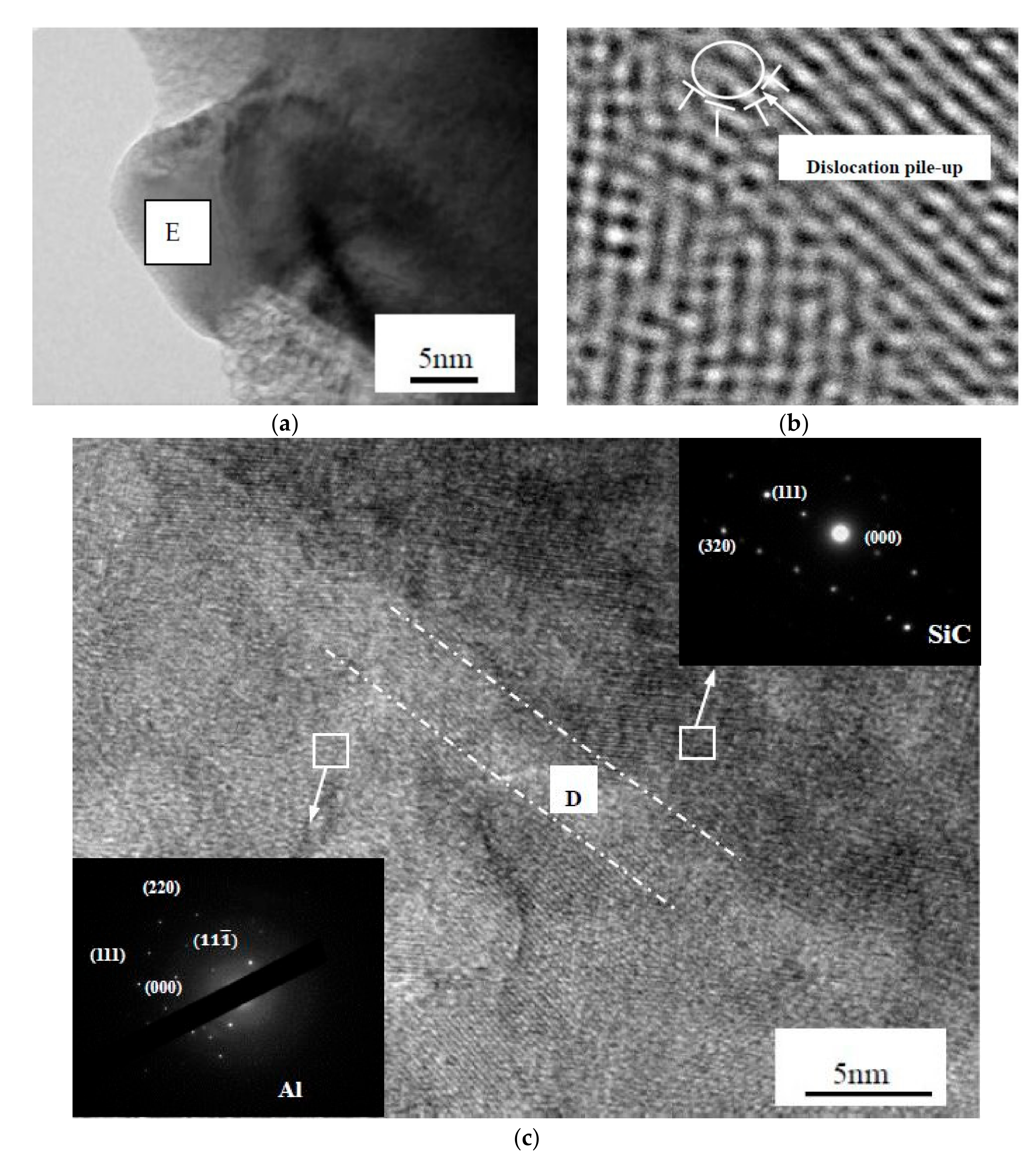
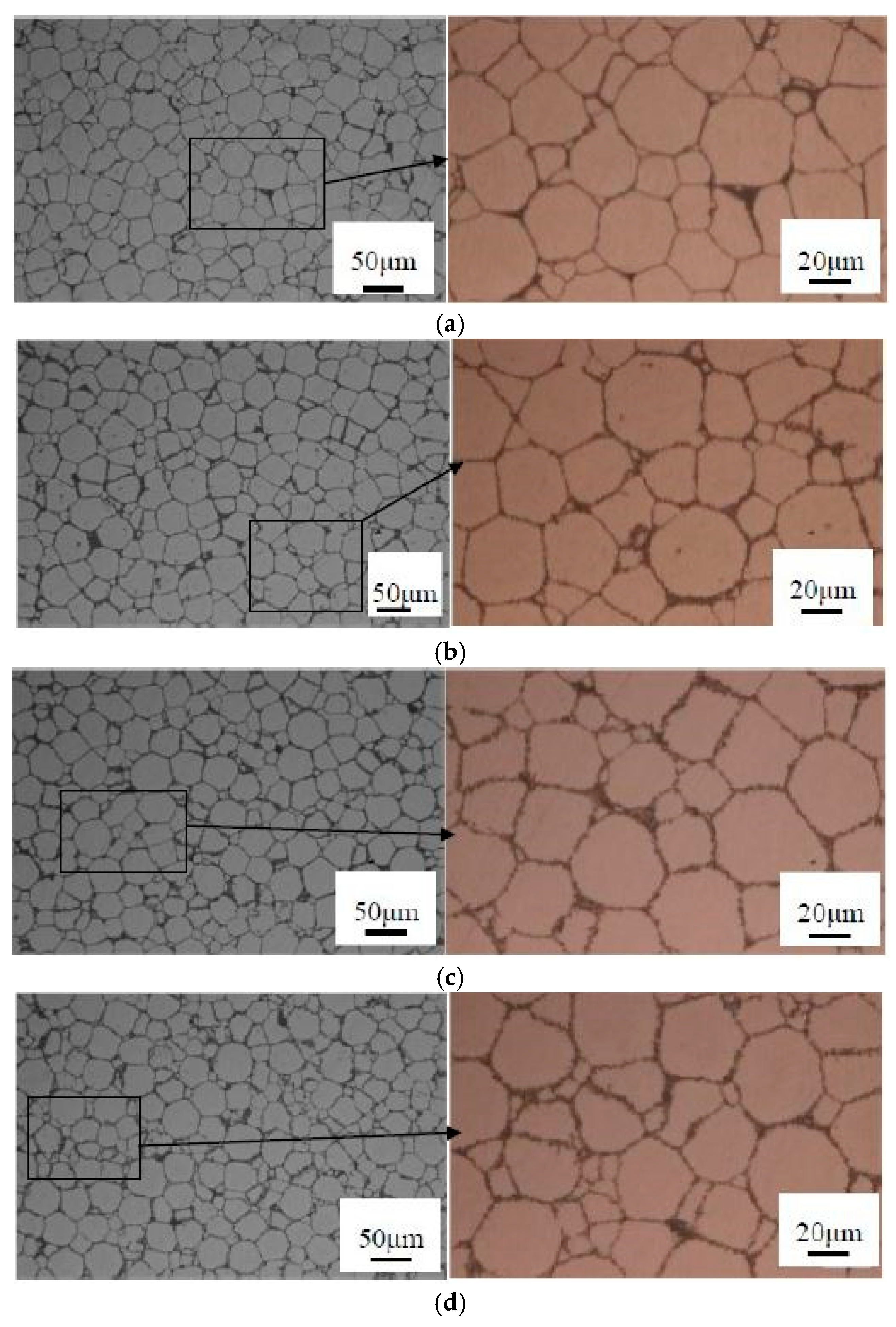
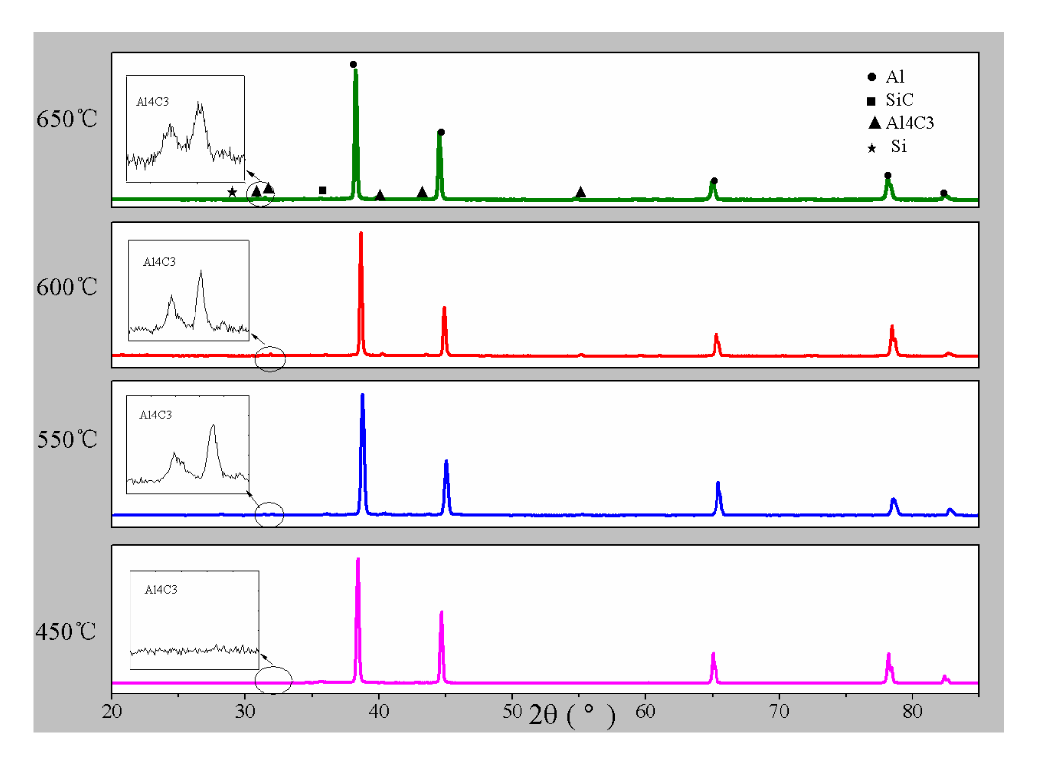
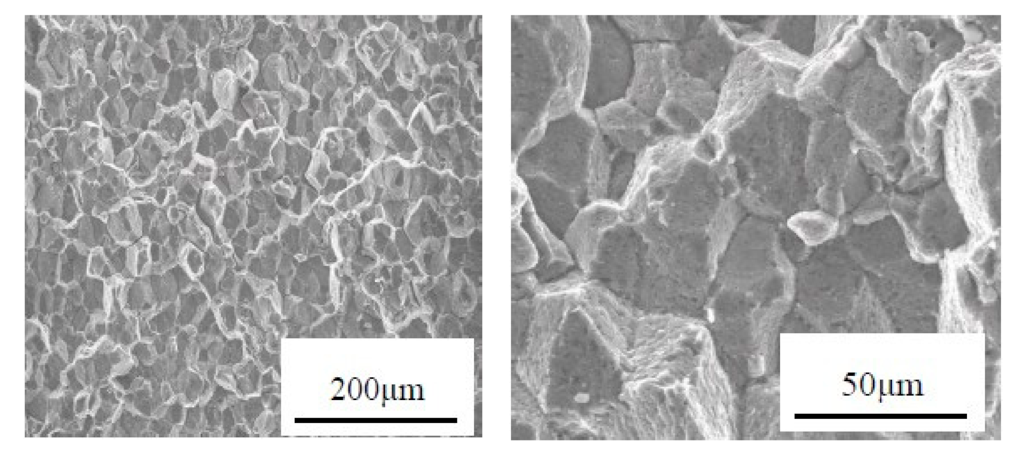
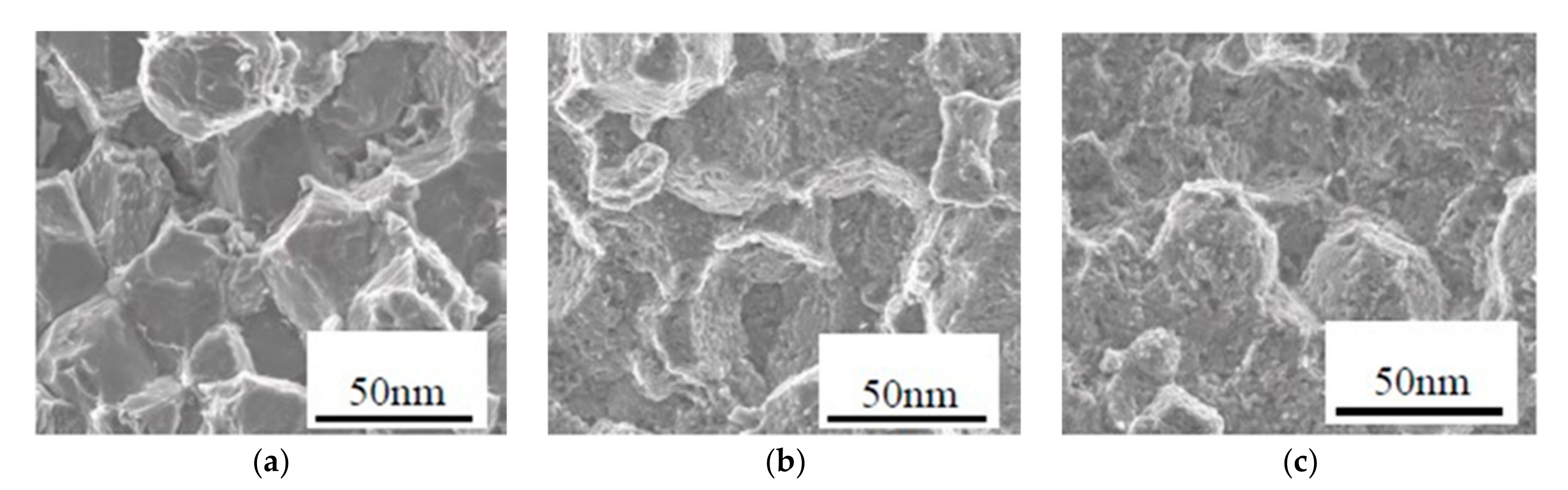
3.2. Effect of the Sintering Temperature on Microstructure and Interface

The samples in this work were fabricated by UHPS method. In this case, the sintering temperature is different from that under normal pressure conditions. Under UHSP conditions, the melting point increase with the pressure rising, according to the Simon–Glatzel Equation (3) [23]
T m = T m 0 ( Ρ / A + 1 ) B
where P is pressure in GPa and Tm0 is melting temperature in Kelvin at 100 kPa. Therefore, it plays a great role in melting. Yuan [24] prepared AA6061/30 vol.% N-SiCp composite by hot pressing sintering in vacuum at 540, 560, 580, 600, 650 °C, and 70 MPa, respectively. At 540 °C, SiC particles agglomerated in the microstructure of composite material, resulting in more obvious voids between each other. As the temperature increases, the voids between the SiC particles became fewer, and there were no large voids in the matrix. At 600 °C, the SiC particles were filled with the Al matrix, and no reinforcement voids appeared, suggesting that the interface bonding is good. Li et al. [25] prepared an Al/SiC powder mixture by high energy ball milling and sintered it by spark plasma sintering at 540 °C and 40 MPa. From the perspective of the microstructure, the overall distribution of SiC particles is uniform in the Al/SiCp composite. For the same content of SiC particles, the agglomerations of nano-scale Al/SiC composites are more common and serious than those of micro-scale Al/SiC composites. For the same size of SiC particles, the Al/SiC composites show more agglomeration as the SiC content increases.
Figure 8 presents the microstructure of AA6061/5 vol.% N-SiCp composites sintered at different temperatures at 4.5 GPa. It seems that, as the temperature increases, the composite has a slight agglomeration of N-SiCp. The boundary between the Al particles and the N-SiCp layer is smooth at 450 °C as indicated in Figure 8a. However, from the enlarged figure in Figure 8b–d, as the temperature rises, some glitch from the interface to the Al particles, indicating that the particles extend from the boundary to the Al particles on both sides, which makes the boundary rough. Additionally, an increasing number of small size particles could be inspected. Because of the low temperature, there are a large number of connected pores between the Al particles or between the N-SiCp, and between the Al particle and N-SiCp. These small pores could diffuse on the sample surface. Due to the continuous reduction and disappearance, the micropores begin to increase, and the similar small pores can be merged by the micropores. This will contribute to the reduction in the total pores and the volume fraction of the composite, as well as the increases in the density. As the temperature further increases, the pore surface becomes smooth and begins to round, but the pores do not reduce or disappear. At this time, under the action of the pressure, the pores move toward the surface of the Al particles, and the atoms in the Al particles move in the opposite direction. The pores are filled and grown into smaller Al particles, illustrating the increment of small-sized particles in the metallographic photograph.
Figure 9 shows the high-magnification microstructure of AA6061/5 vol.% N-SiCp composites at different sintering temperatures and 4.5 GPa. Judging from the microstructure at 450 °C in Figure 9a, the boundary between the particles is relatively smooth. The granules begin to appear at 550 °C, as shown in Figure 9b. The increasing temperature could provide more energy required for the reaction, so the particles tend to grow, as shown in Figure 9d. To determine the phase at the boundary, the XRD analysis was performed on the sample. As shown in Figure 10, the diffraction angle 2θ was partially magnified from 30° to 32.5°. It was observed that no diffraction peak appeared at 450 °C. The diffraction peaks appeared at 550, 600, and 650 °C. The diffraction peak is mainly composed of the Al4C3 phase, indicating that the temperature has a significant effect on the interfacial reaction of Al/N-SiCp composites.

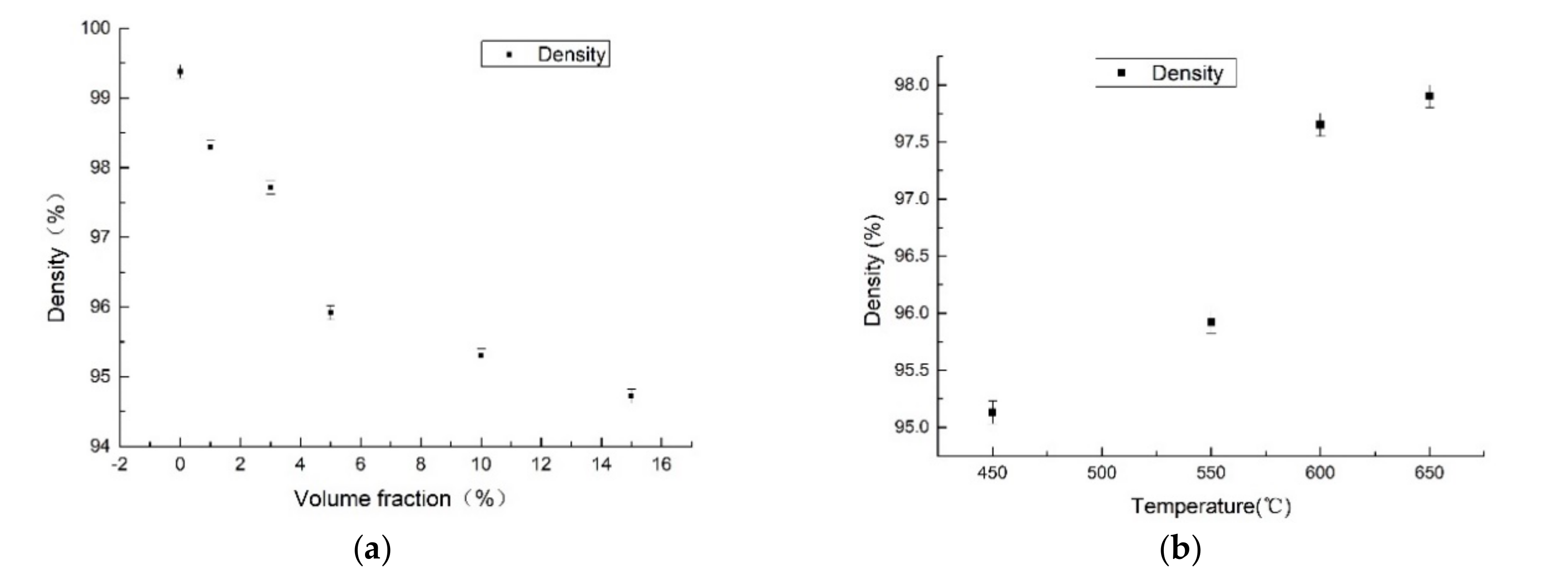
3.3. Evolution Law of Density of Composite Materials

Figure 11 shows the density tendency of AA6061/N-SiCp composite. Figure 11a shows a variation trend of the composite density with volume fraction at 4.5 GPa and 550 °C. It can be seen that the density gradually decreases as the volume fraction of SiCp increases. The density of pure AA6061 reaches 99.38%. For AA6061/1.0 vol.% N-SiCp, the density decreases to about 98%. At this time, the content of N-SiCp is relatively small, and there is no obvious agglomeration. For the small amount of N-SiCp around the Al matrix, the UHSP causes the Al particles to become irregular, and the contact area between particles increases, thereby promoting the diffusion of the elements and leading to the large density of the material. When the volume fraction is increased to 15 vol.%, the density drops to about 95%. In this condition, more agglomeration of the N-SiC could be discovered in the composites. Due to the small self-diffusion coefficient of SiC, and poor ability of sintering, the sintered material seldom achieves full densification. The sintering temperature of the SiC ceramic at normal pressure is as high as 2000 °C, and the density is only 96%. After being sintered at 4.5 GPa and 1300 °C by UHSP, the density of the SiC reported by Xie [26] can just reach 93%. Although UHSP can improve the densification of SiC, to some extent, the volume shrinkage between SiCp is small, and the density cannot reach that of pure Al. Therefore, the larger the volume fraction of N-SiCp is, the smaller the volume shrinkage is during sintering. The small pores between the particles reduce the density of the material.
Figure 11b draws the density variation of AA6061/5 vol.% N-SiCp composites sintered at different temperatures and 4.5 GPa. As the temperature increases, the density of the composite rises gradually. The density is 98% at 650 °C. Ultrahigh pressure could promote the plastic flow of the Al matrix. The higher temperature usually represents the better plastic flow, more volumetric shrinkage, and higher density of the material. Combined with the analysis of the microstructure of the material in Section 3.1, due to the high-temperature effect, the internal atoms of the Al matrix migrate to the large pores formed at the initial stage of sintering, and the filled pores could further increase the density.

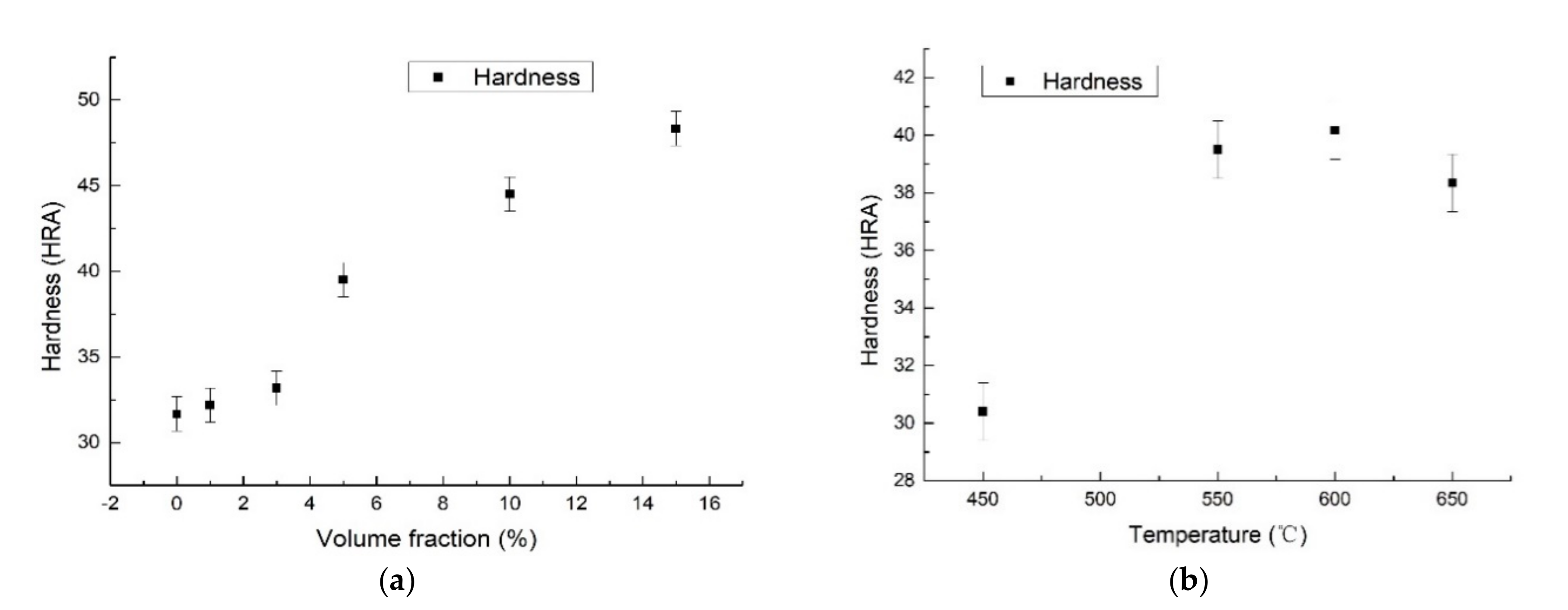
3.4. Evolution of Hardness

Figure 12 shows the hardness variation of the AA6061/N-SiCp composite. Figure 12a shows the hardness variation curve at 4.5 GPa and 550 °C. It can be seen that the hardness gradually increases with the addition of the N-SiCp. The hardness of the AA6061/15vol.% N-SiCp reached up to 48.3 HRA, which was 52.8% higher than that of pure AA6061. For the AA6061/N-SiCp composite, the higher content of N-SiCp can lead to better deformation resistance of the SiC. When the indenter contacts the surface, the higher hardness of the composite could be found. When the volume fraction is high, despite there being many agglomerations in the material interior, the distance among the nanoparticles is very small, therefore the agglomeration has the same bearing capacity for the indenter load. It can be seen from Figure 12b that the hardness of the AA6061/5 vol.% N-SiCp increases with the augment of the temperature at 4.5 GPa. With the temperature increasing, small-sized Al particles crowd more tightly in the microstructure and the interfacial area between N-SiCp and Al matrix increases. It can improve the dispersion uniformity of SiC, dispersion strengthening effect, and the hardness value. However, the hardness is slightly decreased at 650 °C. According to the microstructure analysis in Section 3.1, the SiC can react with the Al substrate at 650 °C according to the following reaction:
4 A l + 3 S i C A l 4 C 3 + 3 S i
The reaction is controlled by a dissolution–diffusion mechanism [27]. The Al4C3 phase is an excessive brittle phase which reduces the interfacial bonding strength between SiC reinforcement and Al matrix. Correspondingly, the mechanical properties are degraded. When the indenter is pressed into the surface, the ability to transfer the load at the interface is lowered, thereby lowering the hardness.

3.5. Research on Mechanical Property

Some of the literature [27,28,29,30,31,32] studied the tensile strength of Al/N-SiCp composites with the different content of SiCp. In this paper, AA6061/N-SiCp composites with 3, 5, and 10 vol.% were prepared at 550 °C. It showed the largest tensile strength of the composite, 314.7 MPa for AA6061/3 vol.% N-SiCp without further treatment. Compared with the AA6061/N-SiCp prepared by powder metallurgy at 600 °C, the tensile strength increased by about 88.2%. The fracture morphology is shown in Figure 13. The surface of the port has a stone-like fracture morphology, which is due to the dispersion of N-SiCp at the grain boundary. The dispersion of N-SiCp forms a large number of fine dimples distributed along the grain boundary. The N-SiCp location is inclined to cause stress concentration, and thus the crack is easy to form at the grain boundary and expands along the grain boundary, resulting in brittle grain boundary fracture. Therefore, the fracture mechanism is an intergranular fracture.
Predecessors [28,29,30,31,32,33,34,35] studied the different Al/SiCp composites with different particle sizes and sintered them at different temperatures. The tensile properties of the Al/SiC matrix composites make a difference at various temperatures.
In this study, AA6061/5 vol.% N-SiCp composites were sintered at 450, 550, and 600 °C, respectively. The highest tensile strength of the composite was obtained at 550 °C, which was about 227 MPa. The fracture morphologies of sample sintered at different temperatures are shown in Figure 14. Figure 14a shows the fracture morphology of AA6061/5 vol.% N-SiCp composites. The fracture mode is similar to that of intergranular fracture. The irregularity in this figure is attributed to the AA6061 particles, which are pressed against each other under UHPS, and are changed from spherical particles to polyhedral shapes. The material fracture first occurs at the sintered neck between the particles. The micro-oxidation of the impurities on Al particles causes the performance of the sintered neck to reduce, corresponding to the internal grain boundary of the material. Thereby, it causes fracture from the neck and leads to intergranular fracture.
Figure 14b shows the fracture morphology of AA6061/5 vol.% N-SiCp composites prepared at 4.5 GPa and 550 °C. The fracture mechanism is a quasi-cleavage fracture, and there is a flat “cleavage-like” region in the figure. The small plane and micropores appear. The sample of Figure 14b is similar to the sample in Figure 14a. Increasing the temperature is more conducive to the elimination of voids and defects so that the sintered neck with excellent performance is formed between the AA6061 particles. The fracture morphology in Figure 14b has a great difference from that in Figure 14a. During the tensile process, the AA6061 matrix is plastically deformed, but N-SiCp distributed among them are small. The uncoordinated deformation causes micro-voids to occur in the small range, which nucleate, grow, and finally connect. Therefore, breaking, dimples, and tearing edges can be inspected. Figure 14c shows the fracture morphology of AA6061/5 vol.% N-SiCp composites sintered at 600 °C. It can be discovered that there are many smaller dimples on the fracture surface. This is mainly due to the agglomeration of N-SiC in the localized area and the SiC will be pulled out during the stretching process.

3.6. Research on Wear Resistance

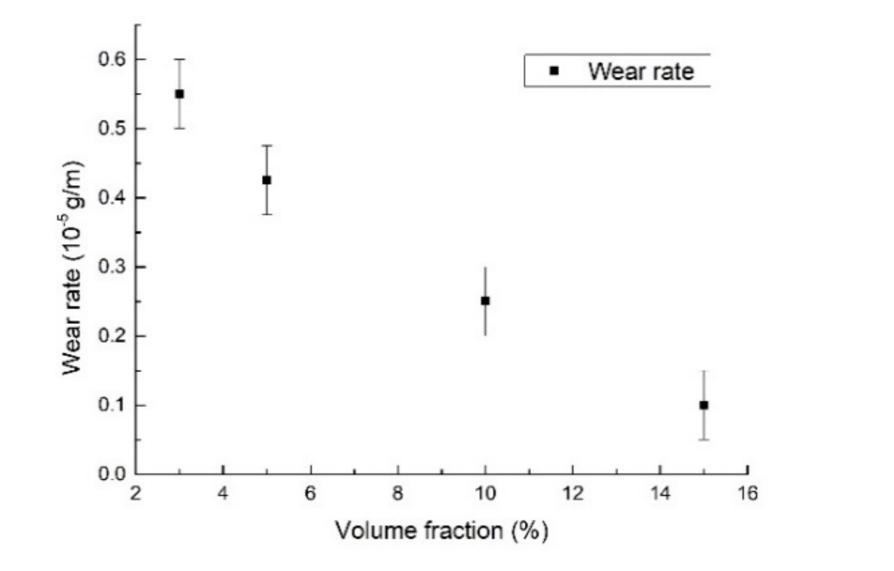
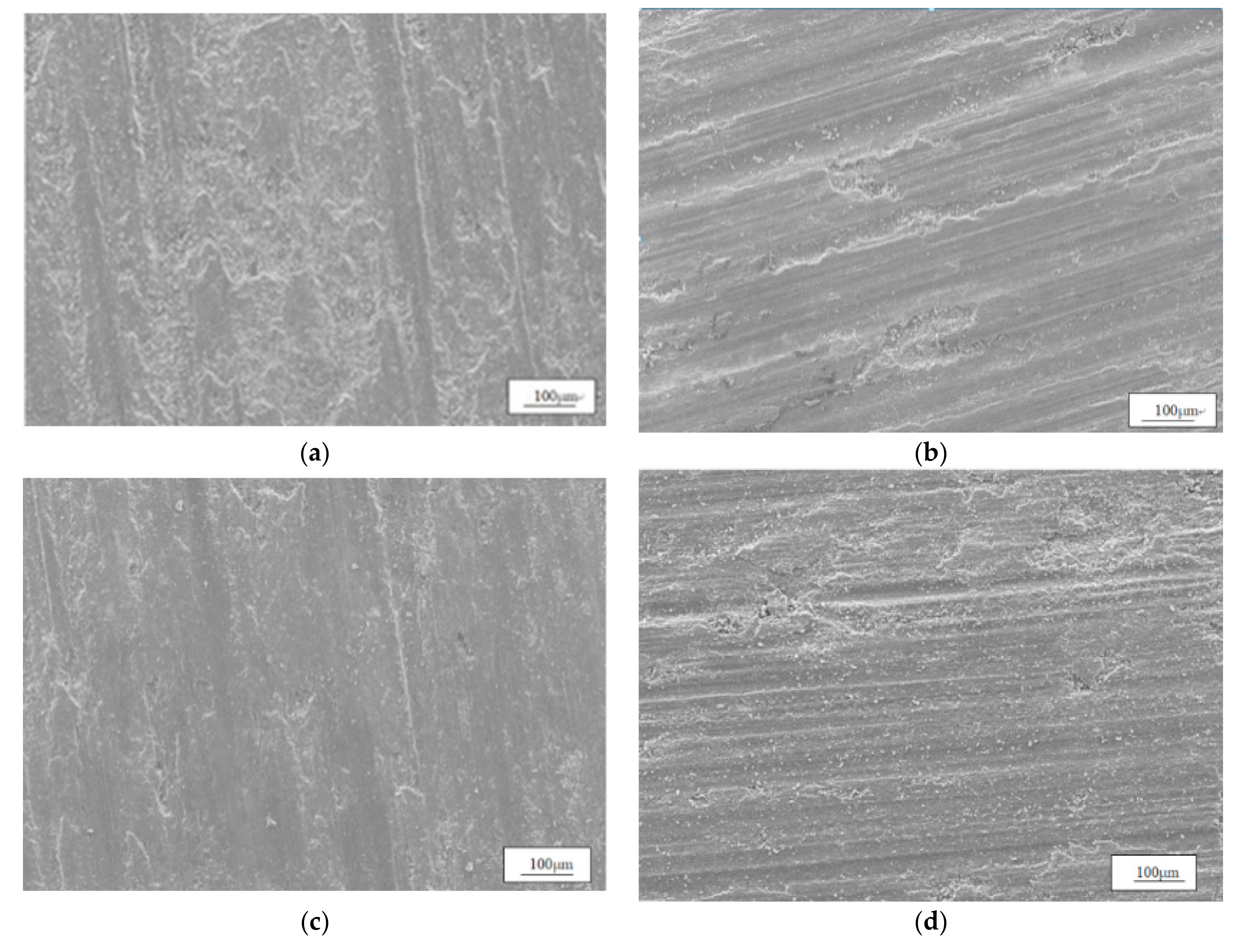
3.6.1. Effect of Volume Fraction of SiCp on Friction and Wear Properties

Figure 15 shows that the wear rate of the AA6061/N-SiCp composite decreases gradually with the increase in the volume fraction of the N-SiC particles. When N-SiCp increases from 3 vol.% to 15 vol.%, the wear rate decreases from 0.55 × 10⁻⁵ g/m to 0.1 × 10⁻⁵ g/m, indicating the wear resistance is improved. This is consistent with the conclusions reported by Zhang et al. [36], who studied the dry sliding friction and wear properties of AA2009/20 vol% SiCp.
Figure 16 shows the friction and wear morphology of AA6061/N-SiCp composites with different content. For AA6061/3 vol.% N-SiCp in Figure 16a, the wear model of the composite is mainly abrasive wear and slight adhesive wear. There are many furrows with different depths on the surface of the sample. The reinforcement effect of SiC is not obvious at the low content of N-SiC. During the wear process, the surface temperature increases, and the Al matrix softens. Under the friction of the grinding disc, the surface layer plastically deforms. Due to the intermolecular force, the Al substrate is cold welded to the surface of the grinding disc. Under the effect of shear stress, the welded joint is sheared and adhered to the surface of the grinding disc, causing the formation of a peeling block. As the friction and wear process progresses, the adhered Al matrix is detached from the surface and forms abrasive grains. Under the effect of the normal load or the forward load of the grinding disc, the Al substrate is cut and the surface is shaped, forming a large number of furrows. For AA6061/5 vol.% N-SiCp, as shown in Figure 16b, the wear form is mainly abrasive wear and adhesive wear. The furrow depth becomes shallow, but the area of the peeling block formed by adhesive wear becomes large. Figure 16c shows the wear morphology of the AA6061/10 vol.% N-SiCp composite. Generally, a greater hardness of the composite surface means better resistance to deformation, and smaller wear rate (only 0.25 × 10⁻⁵ g/m for AA6061/10 vol.% N-SiCp composite). It can be viewed that the number of surface furrows is small, and the wear mechanism is mainly stripping wear. For AA6061/10 vol.% N-SiCp, there are obvious agglomeration phenomena in the microstructure, and defects such as agglomerated pores. Under the effect of tangential load and normal load, the grinding disc is deformed on the sub-surface of the Al matrix. Cracks are nucleated at the pore locations, and the cracks grow or propagate under the external load, which finally shear to the surface and form a peeling layer.
For AA6061/15 vol.% N-SiCp, the wear rate is only 0.1 × 10⁻⁵ g/m. In the meantime, the wear model exhibits mainly fatigue wear, as shown in Figure 16d. Slight scratches and fatigue cracks can be inspected on the surface. For the high content of AA6061/N-SiCp, the surface hardness is high. The periodic load during the wear process causes the subsurface layer to plastically deform, bulge, and generate fatigue cracks. The excessive interface will also reduce the bonding strength, and the convex portion will be crushed to form wear debris. At this time, the abrasive chips are mainly composite particles of N-SiCp and Al particles, and the roundness is good. It is different from the polygonal micro-SiC cutting into the Al substrate. The bonding of the Al substrate and the grinding disc is appropriate, resulting in the enhancement of the wear resistance. The AA6061/N-SiCp composites have a very small size of N-SiCp, and the surface damage is less after the formation of abrasive chips; therefore, it is suggested that the wear resistance is better.

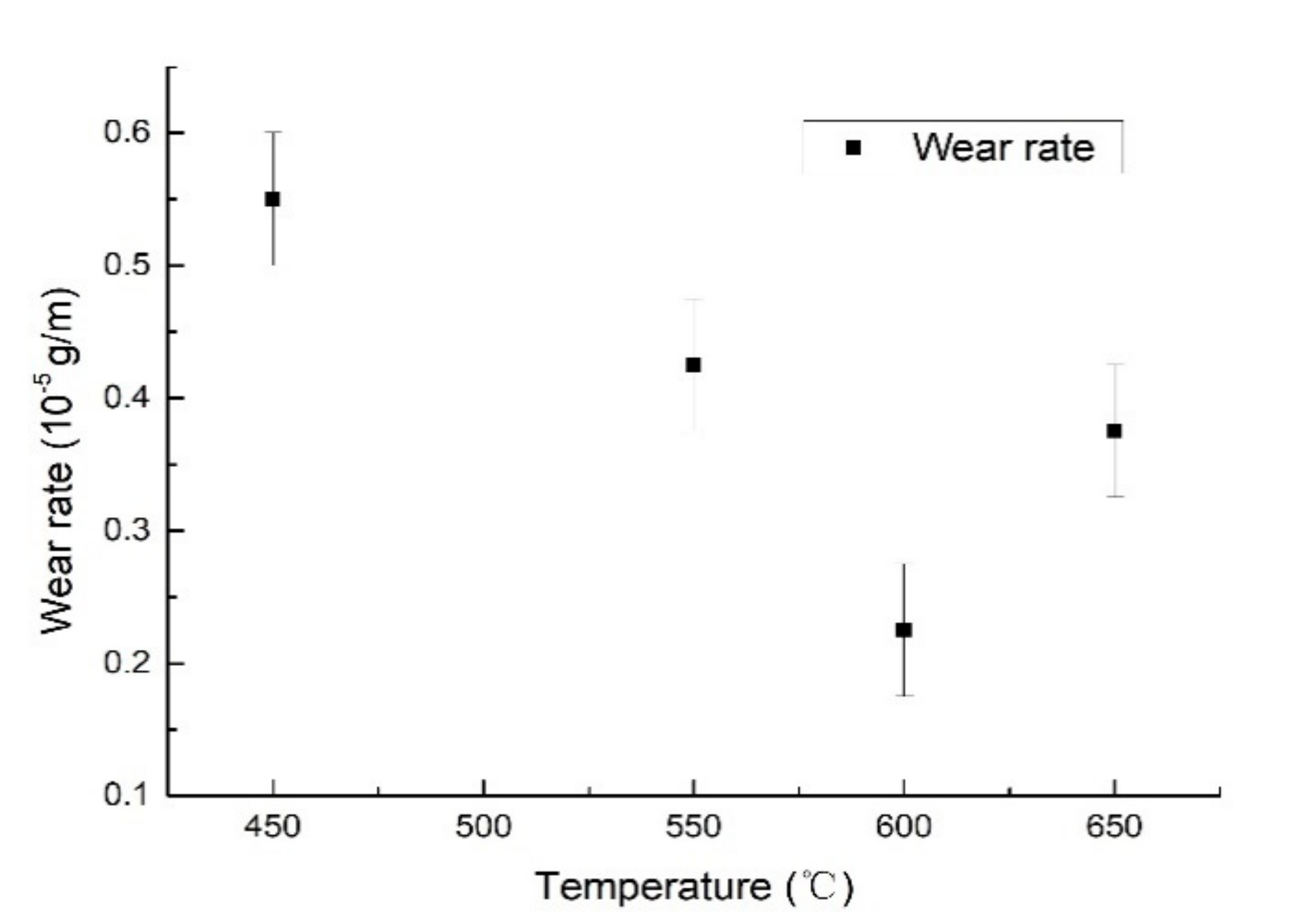
3.6.2. Effect of Sintering Temperature on Wear Resistance

Figure 17 shows the temperature versus wear rate for AA6061/5 vol.% N-SiCp. Figure 17 shows that increasing temperature will cause the wear rate to first decrease and then increase. Wear rate can reach up to the minimum at 600 °C, 0.225 × 10⁻⁵ g/m. As the temperature increases, the hardness will increase, suggesting a better wear resistance of the sample. At 650 °C, the wear rate increases again. This is mainly due to the Al4C3 brittle phase generated at the interface making the bond between the reinforcement and the Al matrix not tight at high temperature and is easily peeled off during the wear process.
Figure 18 shows the friction and wear morphology of AA6061/5 vol.% N-SiCp sintered at 450, 550, 600, and 650 °C, respectively. A large number of exfoliated blocks appear on the surface in Figure 18a. At 450 °C, the density and hardness are relatively low, and the surface has a large plastic deformation zone during the wear process. Additionally, the subsurface layer of the initiation deformation zone of cracks will spall. At 550 °C in Figure 18b, the wear resistance is improved, and some shallow furrows and a small number of peeling pits can be found. It can be assumed that temperature increases the interfacial bonding strength and the hardness, so the wear rate is reduced. With the temperature further increasing up to 600 °C, the wear rate is just 0.22 × 10⁻⁵ g/m. There are fewer small slim scratches and peeling blocks on the surfaces in Figure 18c than those in Figure 18a–d, which means the lightest damage. Meanwhile, a large number of Al particles exists in the microstructure, and the light interface reaction enhances the combination strength, resulting in the best wear resistance. Then, at 650 °C, the wear rate increases, and wear resistance is reduced. A few deep furrows and spalling appear on the surface in Figure 18d. It might contribute to the Al4C3 phase produced at a high temperature. During the wear process, cracks are easily generated at the interface, causing the surface to peel off and abrasive grains. Combined with the hardness in Figure 12b and wear rate in Figure 17, according to the role of Al4C3 in the composites, the wear rate of the composite possessing large hardness is small, indicating a good wear resistance. Therefore, it was also proven that the hardness was enhanced by the formation of the Al4C3 phase, resulting from the increment of wear rate.

4. Conclusions

This paper mainly studies the microstructure and properties of AA6061/N-SiCp composites. The main conclusions are as follows:
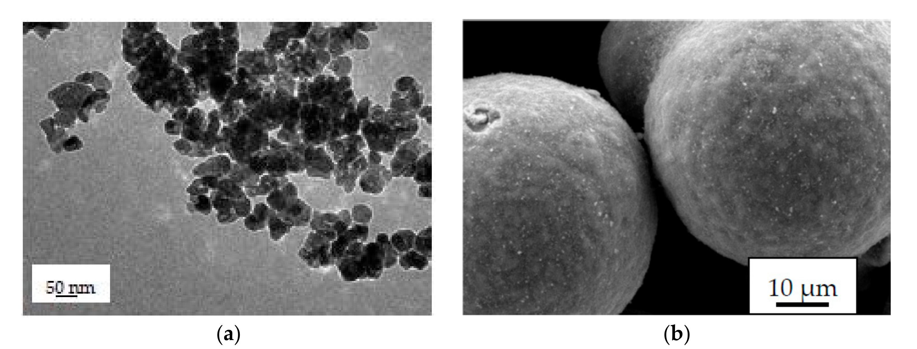
  • For AA6061/1 vol.% N-SiCp and AA6061/3 vol.% N-SiCp, there is almost no agglomeration, and the Al particles become irregular. Higher volume fraction will lead to a thicker N-SiC layer around the Al particles. The rod-like particles appeared at the junction of the two particles. The Al4C3 phase was not detected for AA6061/1 vol.% N-SiCp and AA6061/3 vol.% N-SiCp. The increase in temperature has no significant effect on the agglomeration of N-SiCp, but the higher temperature can generate the better plastic flow of the Al matrix, the filling of the spheroidized pores, and the larger number of small-sized Al particles. The Al4C3 phase begins to appear at the interface at 550 °C. As the temperature increases, the Al4C3 phase distribution at the interface becomes dense.
  • The density of the composites decreases with the increment of the volume fraction of N-SiC and increases with the augment in sintering temperature.
  • The hardness and wear property first increase and then decrease as the temperature increases. The hardness reaches up to 52 HRA, and the wear rate is just 1.0 × 10⁻⁶ g/m at 600 °C. The wear mechanism is mainly composed of abrasive wear and adhesive wear.

Author Contributions

Data curation, Z.C.; Funding acquisition, Y.W.; Supervision, L.X.; Visualization, G.M.; Writing—original draft, E.Y.; Writing—review and editing, C.L. All authors have read and agreed to the published version of the manuscript.

Funding

This work was supported by Research Foundation of China University of Petroleum—Beijing at Karamay, grant numbers XQZX20200016, XQZX20200019 and Science and Technology Plan of Karamay, grant number XQZX20200036.

Conflicts of Interest

The authors declare no conflict of interest.

References

  1. Çinici, H. Investigation of mechanical properties of B4C/SiC/Al2O3 particle reinforced Al2024 hybrid composites. Mater. Res. Express 2019, 6, 096535. [Google Scholar] [CrossRef]
  2. Yang, J.; Long, L.; Li, Y.; Tian, Y.; Wang, J.; Zhang, K. Effect of sintering temperature on wear resistance of Al-Si-based composites reinforced by SiCp. Heat Treat. Met. 2015, 8, 110–113. [Google Scholar]
  3. Hekner, B.; Myalski, J.; Valle, N. Friction and wear behavior of Al-SiC (n) hybrid composites with carbon addition. Compos. Part B Eng. 2017, 108, 291–300. [Google Scholar] [CrossRef]
  4. Chen, X.; Xie, R.; Lai, Z.; Liu, L.; Yan, J.; Zou, G. Interfacial Structure and Formation Mechanism of Ultrasonic-assisted Brazed Joint of SiC Ceramics with Al 12Si Filler Metals in Air. J. Mater. Sci. Technol. 2017, 33, 492–498. [Google Scholar] [CrossRef]
  5. Amouri, K.; Kazemi, S.; Momeni, A.; Kazazi, M. Microstructure and mechanical properties of Al-nano/micro SiC composites produced by stir casting technique. Mater. Sci. Eng. A 2016, 674, 569–578. [Google Scholar] [CrossRef]
  6. Jiang, J.; Wang, Y. Microstructure and mechanical properties of the rheoformed cylindrical part of 7075 aluminum matrix composite reinforced with nano-sized SiC particles. Mater. Des. 2015, 79, 32–41. [Google Scholar] [CrossRef]
  7. Jiang, J.; Chen, G.; Wang, Y. Compression Mechanical Behaviour of 7075 Aluminium Matrix Composite Reinforced with Nano-sized SiC Particles in Semisolid State. J. Mater. Sci. Technol. 2016, 32, 1197–1203. [Google Scholar] [CrossRef]
  8. Sun, C.; Song, M.; Wang, Z.; He, Y. Effect of Particle Size on the Microstructures and Mechanical Properties of SiC-Reinforced Pure Aluminum Composites. J. Mater. Eng. Perform. 2010, 20, 1606–1612. [Google Scholar] [CrossRef]
  9. Liu, S.Y.; Li, W.Z.; Jia, X.Y. Preparation and properties of nano-sized SiC particles reinforced AZ91D magnesium matrix composites. Rare Met. Mater. Eng. 2010, 1, 134–138. [Google Scholar]
  10. Liu, S.; Li, W. Friction and Wear Properties of Nano-Sized SiC Particles Reinforced AZ91D Composites. Spec. Cast. Nonferrous Alloy 2012, 10, 935–939. [Google Scholar]
  11. Gao, H.X.; Wang, H.L.; Yang, D. Study on single nanoparticles and nano/micro SiC particles reinforced aluminum composites. Powder Metall. Technol. 2016, 1, 11–15. [Google Scholar]
  12. Zhang, L. The Fabrication, Microstructures and Mechanical Properties of Micro-And Nano-Sized SiCp/Al2014 Composites. Master’s Thesis, Jilin University, Jilin, China, 2015. [Google Scholar]
  13. El-Kady, O.; Fathy, A. Effect of SiC particle size on the physical and mechanical properties of extruded Al matrix nanocomposites. Mater. Des. 2014, 54, 348–353. [Google Scholar] [CrossRef]
  14. Wang, H.; Xie, J.; Hao, S. Effort of SiC particle size on the microstructures and properties of aluminum matrix composites. Powder Metall. Technol. 2013, 31, 344–348. [Google Scholar]
  15. Li, C.Y.; Wang, Y.S.; Xu, Y.; Liu, Y.; Lu, N.N.; Mi, G.F. Microstructure and Mechanical Property of Compact Graphite/6061Al Composite Prepared by Ultra-High Pressure Sintering. Appl. Sci. 2020, 10, 5107. [Google Scholar] [CrossRef]
  16. Xiang, Z.; Nie, J.; Wei, S.; Zuo, T. Mechanical Properties of 15% SiCp/6061Al Composites with Heat Treatment and Different SiCp Sizes. Chin. J. Rare Met. 2015, 39, 998–1003. [Google Scholar]
  17. Nirala, A.; Soren, S.; Kumar, N.; Dwivedi, V.; Kaushal, D. A comprehensive review on stir cast Al-SiC composite. Mater. Today: Proc. 2020, 21, 1610–1614. [Google Scholar] [CrossRef]
  18. Schilling, J.S. The use of high pressure in basic and materials science. J. Phys. Chem. Solids 1998, 59, 553–568. [Google Scholar] [CrossRef]
  19. Chang, R.; Rhodes, C.G. High-Pressure Hot-Pressing of Uranium Carbide Powders and Mechanism of Sintering of Refractory Bodies. J. Am. Ceram. Soc. 1962, 45, 379–382. [Google Scholar] [CrossRef]
  20. Li, D.C. Study on SIMA Semi-Solid Forming of Aluminum Alloy and Its Particles Reinforced Composites. Master’s Thesis, Jilin University, Jilin, China, 2009. [Google Scholar]
  21. Clyne, T.W.; Withers, P. An Introduction to Metal Matrix Composite; Cambridge University Press: Cambridge, UK, 1993. [Google Scholar]
  22. Van Swygenhoven, H.; Derlet, P.M.; Frøseth, A.G. Nucleation and propagation of dislocations in nanocry stalline fcc metals. Acta Mater. 2006, 54, 1975–1983. [Google Scholar] [CrossRef]
  23. Simon, F.; Glatzel, G. Bemerkungen zur Schmelzdruckkurve. J. Inorg. General Chem. 1929, 178, 309–312. [Google Scholar] [CrossRef]
  24. Yuan, G.S.; Li, M.K.; Wang, Z.Y. Effect of sintering temperature on mechanical properties and microstructure of SiCp/6061Al composite. Hot Work Technol. 2017, 46, 123–125. [Google Scholar]
  25. Li, H.Y.; Ouyang, X.; Zhao, S.X. Microstructure and properties of nano-SiC/Al composites fabricated by SPS. Min. Metall. Eng. 2016, 36, 113–116. [Google Scholar]
  26. Xie, M.L.; Luo, D.L.; Xian, X.B. Nano-SiC ceramic sintering at ultra-high pressure and high temperature. J. Inorg. Mater. 2008, 39, 811–814. [Google Scholar] [CrossRef]
  27. Jin, P.; Xiao, B.L.; Wang, Q.Z. Effect of hot pressing temperature on microstructure and mechanical properties of SiC particle reinforced aluminum matrix composites. Acta Metall. Sin. 2011, 47, 298–304. [Google Scholar]
  28. Ardakani, M.R.K.; Khorsand, S. Application of compocasting and cross accumulative roll bonding processes for manufacturing high-strength, highly uniform and ultra-fine structured Al/SiCp nanocomposite. Mater. Sci. Eng. A 2014, 592, 121–127. [Google Scholar] [CrossRef]
  29. Hua, Q.Q. Preparation of power metallurgy submicron SiC particles reinforced Al based composites and mechanical properties. Spec. Cast. Nonferrous Alloys 2017, 34, 411–414. [Google Scholar]
  30. Tian, X.F.; Xiao, B.L.; Fan, Z. Mechanical properties of nano-SiCp reinforced 2024 aluminum composite. Chin. J. Rare Met. 2005, 29, 521–525. [Google Scholar]
  31. Hao, S.M.; Xie, P.; Hang, W. Effects of size of micrometer SiC particles on tensile properties and strengthening mechanism of SiCp reinforced aluminum matrix composites. Trans. Mater. Heat Treat. 2014, 35, 13–18. [Google Scholar]
  32. Sivakumar, G.; Ananthi, V.; Ramanathan, S. Production and mechanical properties of nano SiC particle reinforced Ti-6Al-4V matrix composite. Trans. Nonferrous Met. Soc. China 2017, 27, 82–90. [Google Scholar] [CrossRef]
  33. Li, B.L. Synthesis Microstructure and Properties of Nano-SiCp/Al Composite. Master’s Thesis, Harbin Institute of Technology, Harbin, China, 2013. [Google Scholar]
  34. Li, Y. Structure, Performance and Hot Deformation of Nano-Sized SiCp/108Al Composite. Master’s Thesis, Henan University of Science and Technology, Henan, China, 2017. [Google Scholar]
  35. Riquelme, A.; Rodrigo, P.; Escalera-Rodríguez, M.D.; Rams, J. Characterisation and mechanical properties of Al/SiC metal matrix composite coatings formed on ZE41 magnesium alloys by laser cladding. Results Phys. 2019, 13, 102160. [Google Scholar] [CrossRef]
  36. Zhang, Z.F.; Zhang, L.C.; Mai, Y.-W. Particle effects on friction and wear of aluminium matrix composites. J. Mater. Sci. 1995, 30, 5999–6004. [Google Scholar] [CrossRef]
Figure 1. SEM morphology of AA6061 powder.
Applsci 10 07363 g001
Figure 2. SEM micrographs of N-SiC powder (a) and AA6061/N-SiC powder mixture (b).
Applsci 10 07363 g002
Figure 3. OM micrograph of AA6061/N-SiCp composites sintered at 550°C with 1 (a), 3 (b), 5 (c), 10 (d) and 15 (e) vol.% N-SiCp.
Applsci 10 07363 g003
Figure 4. SEM micrographs of AA6061/N-SiC composites sintered at 550°C with 3 (a), 5 (b), 10 (c) and 15 (d) vol.% N-SiCp.
Applsci 10 07363 g004
Figure 5. EDS-SEM analysis: (a) The analysis of point 1 of AA6061/10 vol.% N-SiC, (b) The analysis of line scanning 2 of AA6061/15 vol.% N-SiC sintered at 550 °C.
Applsci 10 07363 g005
Figure 6. XRD diffraction pattern of AA6061/N-SiCp sintered at 4.5 GPa and 550 °C with different content of N-SiCp particles.
Applsci 10 07363 g006
Figure 7. (a) TEM micrograph of AA6061/1 vol.% N-SiCp sintered at 550 °C and 4.5 GPa, (b) IFFT image of zone D in Figure 7c, (c) HRTEM image of zone E in Figure 7a.
Applsci 10 07363 g007
Figure 8. OM micrograph of AA6061/5 vol.% N-SiC composites sintered at 450 (a), 550 (b), 600 (c), 650 (d) °C.
Applsci 10 07363 g008
Figure 9. SEM micrographs of AA6061/5 vol.% N-SiC composites sintered at 450 (a), 550 (b), 600 (c) and 650 (d) °C.
Applsci 10 07363 g009
Figure 10. XRD patterns of AA6061/5 vol.% N-SiCp sintered at different temperatures: 450, 550, 600, and 650 °C.
Applsci 10 07363 g010
Figure 11. The curve of the relative density of AA6061/N-SiCp composite: Relationship between relative density and volume fraction for AA6061/5 vol.% N-SiCp sample (a). Relationship between relative density and sintering temperature at 4.5 GPa for AA6061/5 vol.% N-SiCp sample (b).
Applsci 10 07363 g011
Figure 12. The curve of the hardness of AA6061/N-SiCp composite at 4.5 GPa: Relationship between hardness and volume fraction: 0, 1, 3, 5, 10, 15 vol.% (a), Relationship between hardness and sintering temperature: 450, 550, 600, 650 °C (b) for AA6061/5 vol.% N-SiCp sample.
Applsci 10 07363 g012
Figure 13. Fracture morphology of AA6061/3 vol.% N-SiCp composite sintered at 550 °C.
Applsci 10 07363 g013
Figure 14. SEM micrograph of the fracture surface of AA6061/5 vol.% N-SiCp composites produced sintered at 450 (a), 550 (b), 600 °C (c), respectively.
Applsci 10 07363 g014
Figure 15. Effect of N-SiCp volume fraction on the wear rate of the composite under 4.5 GPa and 550 °C.
Applsci 10 07363 g015
Figure 16. Wear morphology of N-SiCp/Al composite with different volume fraction under 4.5 GPa and 550 °C with 3 (a), 5 (b), 10 (c), 15 (d) vol.% N-SiCp.
Applsci 10 07363 g016
Figure 17. Effect of sintering temperature on the wear rate of AA6061/5 vol.% N-SiCp under 4.5 GPa.
Applsci 10 07363 g017
Figure 18. Wear morphology of AA6061/5 vol.% N-SiCp sintered at: 450 (a), 550 (b), 600 (c), 650 (d) °C.
Applsci 10 07363 g018
Table 1. Chemical component of AA6061 (wt%).
SiCuMgZnMnTiGrFeAl
0.3930.2460.960.0010.0860.0150.050.1balance
Publisher’s Note: MDPI stays neutral with regard to jurisdictional claims in published maps and institutional affiliations.

