Article

Area-Efficient Short-Time Fourier Transform Processor for Time–Frequency Analysis of Non-Stationary Signals

1
School of Electronics and Information Engineering, Korea Aerospace University, Goyang-si 10540, Korea
2
The Department of Information and Communication Engineering, Sejong University, Seoul 05006, Korea
*
Author to whom correspondence should be addressed.
Appl. Sci. 2020, 10(20), 7208; https://doi.org/10.3390/app10207208
Submission received: 15 September 2020 / Revised: 9 October 2020 / Accepted: 10 October 2020 / Published: 15 October 2020
(This article belongs to the Special Issue VLSI Architectures for Signal Processing)

Abstract

:
In this paper, we propose an area-efficient short-time Fourier transform (STFT) processor that can perform time–frequency analysis of non-stationary signals in real time, which is essential for voice or radar-signal processing systems. STFT processors consist of a windowing module and a fast Fourier transform processor. The length of the window function is related to the time–frequency resolution, and the required window length varies depending on the application. In addition, the window function needs to overlap the input data samples to minimize the data loss in the window boundary, and overlap ratios of 25%, 50%, and 75% are generally used. Therefore, the STFT processor should ideally support a variable window length and overlap ratio and be implemented with an efficient hardware architecture for real-time time–frequency analysis. The proposed STFT processor is based on the radix-4 multi-path delay commutator (R4MDC) pipeline architecture and supports a variable length of 16, 64, 256, and 1024 and overlap ratios of 25%, 50%, and 75%. Moreover, the proposed STFT processor can be implemented with very low complexity by having a relatively lower number of delay elements, which are the ones that increase complexity in the most STFT processors. The proposed STFT processor was designed using hardware description language (HDL) and synthesized to gate-level circuits using a standard cell library in a 65 nm CMOS process. The proposed STFT processor results in logic gates of 197,970, which is 63% less than that of the conventional radix-2 single-path delay feedback (R2SDF) based STFT processor.

1. Introduction

Short-time Fourier transform (STFT) is a time–frequency analysis technique for non-stationary signals. The STFT segments a time-domain input signal into several separated or overlapped frames by multiplying the signal with a window function and then applies the fast Fourier transform (FFT) to each frame. Because Fourier transforms are performed while moving the window, this technique can measure the frequency content changes of a signal over time [1,2,3]. Owing to these characteristics, the STFT is widely used in various fields that require frequency measurement over time, such as radar systems and voice-signal processing systems. In particular, to carry out these measurements in real-time, it is necessary to implement the STFT algorithm into a hardware processor [4,5,6,7,8,9,10].
An STFT processor consists of a windowing module and an FFT processor. The available types of FFT hardware architectures that can be considered for designing an STFT processor are the single butterfly architecture, the pipeline architecture, and the parallel architecture. Among them, the pipeline architecture offers a good tradeoff between hardware complexity and throughput rate; therefore, it is an attractive option for implementing the FFT processor in an STFT processor. Pipeline architectures are classified as single-path delay feedback (SDF) architecture and multi-path delay commutator (MDC) architecture. The SDF pipeline architecture is the more commonly used out of the two because it provides the lowest number of nontrivial multiplications, which are the most complex operations to perform in a single channel [11]. However, when using multiple data channels, the SDF FFT processor must be implemented in each channel. Thus, there is a problem in that hardware complexity increases linearly with the number of data channels. In the case of multi-channel FFT, Sansaloni et al. suggested that the MDC FFT processor could be implemented in a lower area than the SDF FFT processor [12].
The windowing module multiplies the non-stationary signal with the window function to add a time dimension and reduces the side lobes in the spectrum, thereby reducing the spectral leakage caused by noise. In addition, the type and length of the window function used in the windowing module are closely related to performance. Consequently, the type and length of the window function appropriate for each application are different [13].
The length of the window function in the STFT is related to the resolution of the signal. Long windows provide higher frequency resolution but lower time resolution. Analogously, short windows provide higher time resolution but lower frequency resolution. Because the required time and frequency resolutions vary between applications using STFT processors, the window length should ideally be variable to support various time and frequency resolutions [14,15,16]. STFT processors generally use several types of tapering windows, such as Hamming, Hanning, and Kaiser, to reduce the side lobes in the spectrum and mitigate spectral leakage due to noise. However, tapering windows are usually very small or zero at the beginning and end, resulting in data loss near the boundary. To solve this problem, we need to minimize the loss of data by overlapping window functions. The overlap ratio that minimizes data loss varies depending on the type of window function used. According to Heinzel et al., to minimize data loss when using a window function, it is typically used with a 0%, 25%, 50%, or 75% overlap [17]. Therefore, depending on the type of window used, the STFT processor should be capable of changing the overlap ratio to the one that minimizes data loss.
Various studies have been conducted to improve the performance of STFT processors. Zhang et al. implemented an STFT processor that uses several SDF FFT processors in parallel to support a high overlap ratio, but this increases complexity [18]. In addition, Srinivas et al. implemented the STFT processor as a single SDF FFT processor and reused the FFT calculation results to reduce hardware area and latency [19]. However, this STFT processor can only use a rectangular window and supports a 50% overlap only.
Therefore, in this paper, we propose an STFT processor that provides a 0/25/50/75% variable overlap ratio to minimize data loss depending on the type of window used and 16/64/256/1024-point variable window lengths to support various time–frequency resolutions. In particular, because the proposed STFT processor is based on a radix-4 MDC (R4MDC) architecture, it has lower complexity than architectures using several SDF FFT processors.
The remainder of this paper is organized as follows. Section 2 describes the STFT algorithm and general hardware architectures. Section 3 presents the hardware architecture of the proposed STFT processor. Section 4 presents the design and implementation results of the proposed STFT processor. Finally, Section 5 concludes the paper.

2. STFT Algorithm and Hardware Architecture

The STFT is defined as
X S T F T k , n = m = 0 N 1 x m + n H w m W N k m , 0 k N 1 , 1 H N
where x [ m ] is the input signal, w [ m ] is the window function, N is the length of the window, n is the time frame index, and k is the frequency index. Here, H denotes the hop length, and the overlap length between adjacent frames is N H . In addition, the overlap ratio between consecutive frames is ( N H ) / N . At a specific time n H , the signal x [ m ] is multiplied by the window function w [ m ] . Therefore, Equation (1) can be defined as the FFT operation of x [ m + n H ] w [ m ] . The STFT processor measures the frequency over time by moving the window function w [ m ] along the signal x [ m ] according to the hop length and performing the FFT operation on samples inside the window. The flow of the algorithm is shown in Figure 1.
The STFT processor should be capable of varying the overlap ratio according to the window type to minimize the data loss due to the tapering window. Therefore, the STFT processor needs a windowing module that overlaps the input data stream at a certain overlap ratio and multiplies the signal by the window function. Figure 2 shows how windows are overlapped at ratios of 0%, 25%, 50%, and 75% in the windowing module. Figure 2b,c shows window overlaps at ratios of 25% and 50%, respectively, and that the windowing module requires at least two output channels to overlap a single data stream by 25% and 50%. Figure 2d shows a window overlap of 75%. In this case, the windowing module requires at least four output channels to overlap a single data stream by 75% overlap ratio. In addition, when the windowing module supports a 75% overlap ratio, channels 1 and 3 of the windowing module have a 50% overlap ratio, channels 1 and 4 have a 25% overlap ratio, and channel 1 has a 0% overlap ratio. In other words, a windowing module that supports a 75% overlap ratio also includes 0%, 25%, and 50% overlap ratios. Therefore, to support a variable overlap ratio, the windowing module should be able to receive a single data stream and create four data streams overlapped by 75% between each channel.
The 75% overlapped data streams are output through the four channels of the windowing module as input to the FFT processor, which performs the FFT operation to measure the frequency content changes over time. As previously stated, current FFT hardware architectures that can be considered for designing an STFT processor are generally classified as single butterfly architectures, pipeline architectures, and parallel architectures. The parallel architecture has the most significant advantage in terms of throughput rate but has high hardware complexity. The single butterfly architecture has the lowest hardware complexity, but offers a low throughput rate. In contrast, the pipeline architecture offers a good tradeoff between throughput and complexity and is consequently used in many fields [20,21,22].
Pipeline architectures in FFT processors are classified as SDF and MDC. In the SDF architecture, the input sequence goes through a single channel and is reordered by a modified butterfly computational unit. Since this architecture requires only one complex multiplier per butterfly unit, it has low complexity and is commonly used in STFT processors. However, as shown in Figure 3, four FFT processors are required to design an STFT processor with a variable overlap ratio of maximum 75% using an SDF FFT processor. Thus, a large hardware area is required. In contrast, MDC FFT processors process data through multiple channels and perform an alignment of the data according to a signal-flow graph (SFG) using delay elements [23]. In the case of four-channel FFT, the R4MDC FFT processor can be implemented in a lower area than four radix-2 SDF (R2SDF) FFT processors [24]. Therefore, designing an STFT processor that supports a variable overlap ratio using an MDC FFT processor requires a single FFT processor instead of four SDF FFT processors, as shown in Figure 4.

3. Hardware Architecture of the Proposed STFT Processor

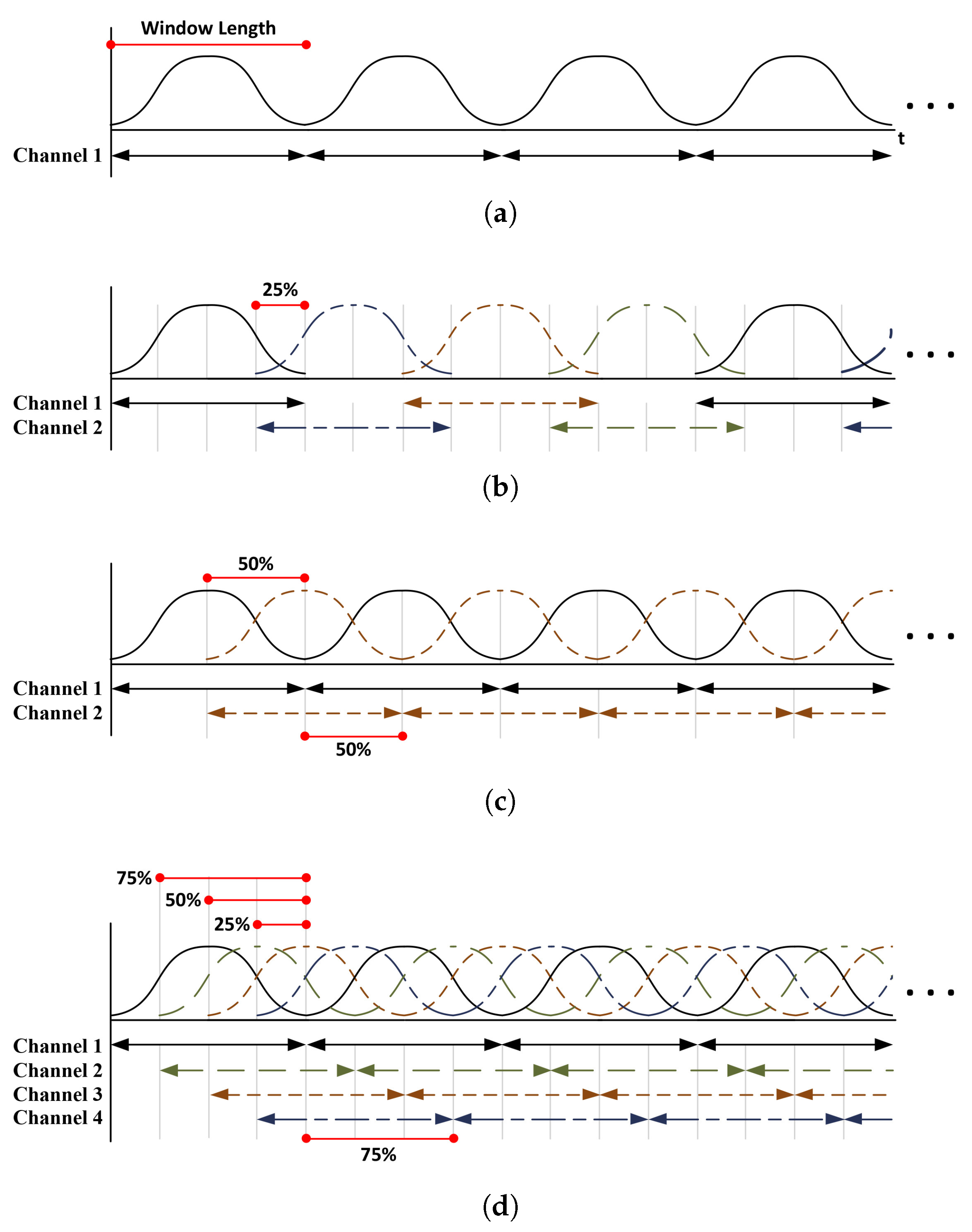
3.1. Variable Overlap Ratio of the Proposed STFT Processor

Because a single data stream is input to the STFT processor, we need a windowing module (WM) that receives a single data stream and creates four data streams that overlap by 75% between each channel. For a window length of N , the input and output data flows of the WM are as shown in Figure 5. The output data of channel 1 is delayed by 3 N / 4 cycles of the input data stream, and the output data of channel 2 is delayed by N / 2 cycles of the input data stream. The output data of channel 3 is delayed by N / 4 cycles of the input data stream. Finally, the output data stream of channel 4 is output without delaying the input data stream. The FFT operation starts after the first data of channel 1 is delayed by 3 N / 4 cycles. That is, the FFT operation starts when the data on channel 1 and channel 2, channel 2 and channel 3, channel 3 and channel 4 overlap by 75% each and are input into the FFT processor.
As previously stated, it is possible to change the overlap ratio by approximately selecting output channels of the FFT processor. For example, we can obtain 50% overlapped STFT result by selecting output channels along to blue arrow in Figure 6, because channels 1 and 3 overlap by 50%. Similarly, 25% and 75% overlapped STFT results can be obtained along to red and green arrows, respectively. If only channel 1 is selected, we can obtain STFT result of the non-overlapped data streams.

3.2. Hardware Architecture of the Proposed STFT Processor

Figure 7 shows the hardware architecture of the proposed STFT processor, which supports a 0/25/50/75% variable overlap ratio to minimize the loss of information depending on the type of window used. It also supports 16/64/256/1024-point variable window lengths to provide various time–frequency resolutions. The hardware architecture of the proposed STFT processor consists of a WM, four data mapping modules (DMM1, DMM2, DMM3, DMM4), a data reordering module (DRM), five radix-4 butterfly modules (R4BM1, R4BM2, R4BM3, R4BM4, R4BM5). The principle of operation is as follows. The input single data stream is reconstructed according to the length of the predefined window by the WM and converted into four overlapped data streams. Moreover, the four data streams are multiplied by the predefined window and input to the next stage. In the case of 1024-point STFT, the four-channel data streams reconstructed by the WM are input to R4BM1 by a multiplexer to perform the 1024-point STFT operation. In the case of 256-point STFT, the four-channel data streams are input to R4BM2. In the case of 64-point STFT, the four-channel data streams are input to R4BM3. In the 16-point STFT, four channels of data streams are input to R4BM4.

3.2.1. Windowing Module (WM)

If the conventional R4MDC architecture is applied to the STFT processor, there is a problem in that the area required is higher owing to the first DMM that reconstructs the data before the first R4BM input [25]. In the case of 1024-point R4MDC FFT, 3072 delay elements are required for the subsequent R4BM (R4BM1). However, in the proposed STFT processor, the WM converts the input single data stream into four 75% overlapped data streams and reconstructs the data with an alignment pattern corresponding to that required by the first R4BM as shown in Figure 8. Therefore, in the proposed architecture, a DMM for performing data alignment for the first R4BM was not used. In this way, the required number of delay elements is only 768, thereby enabling an implementation with lower complexity. In addition, since the proposed WM should support variable lengths of 16/64/256/1024 points, we use multiplexers to determine the required data alignment pattern for 16/64/256/1024 points.

3.2.2. Data Reordering Module (DRM)

The DRM makes the four-channel data after the FFT operation match the predefined overlap ratio, as shown in Figure 6, and then outputs it. In this paper, the DRM is implemented using the architecture proposed in [26], and Figure 9 shows the hardware architecture of the proposed DRM. The pre-commutator reconstructs four-channel input data for the dual-port RAM (DPRAM). Because we need to support 16/64/256/1024-point variable lengths, we use multiplexers to enforce the necessary data alignment pattern for the 16/64/256/1024-point FFTs, respectively. The output of DPRAM is reconstructed and used as the input of the post-commutator, which uses multiplexers to reconstruct the data so that it matches the MDC data structure. The parallel-to-serial (P/S) converter selects data from the four-channel output of the post-commutator in the order that matches the predefined overlap ratio and outputs it as a single stream.

4. Implementation Results

To verify that the proposed STFT processor architecture is efficient in terms of hardware complexity, we implemented STFT processors using R2SDF, R4MDC, and the proposed architectures. A 12-bit word for the real and imaginary data paths was selected to satisfy the requirement for a signal-to-quantization-noise ratio (SQNR) of 40 dB. Three STFT processors were designed using hardware description language (HDL) and synthesized for an operating frequency of 200 MHz with a 65 nm CMOS standard cell library using Synopsys Design Compiler tool [27]. Table 1 summarizes the comparison results in terms of the number of logic gates. As shown in the Table, the proposed STFT processor architecture reduces the number of logic gates by 54% compared with the conventional R4MDC-based STFT processor and by 63% compared with the R2SDF-based STFT processor.
Table 2 shows the comparison results between the proposed STFT processor and the STFT processor described in [18]. To make a fair comparison, we normalized the area as
A n o r m = A r e a × 10 3 T e c h / 65 n m 2 × log 2 N × α
where N , α , and T e c h are the window length, maximum overlap ratio, and the process technology in nanometers, respectively. Even though the design of [18] can support a higher overlap ratio than the proposed STFT processor, it only supports a window length of 32. It also requires an approximately 2.3 times larger area than the proposed STFT processor.

5. Conclusions

In this paper, we propose the design of an STFT processor architecture that supports a variable overlap ratio of 0/25/50/75% to minimize the data loss depending on the type of window used as well as variable window lengths of 16/64/256/1024 to provide various time–frequency resolutions. In the proposed WM architecture for our R4MDC-based STFT processor, the single-channel data stream is converted into four overlapped data streams by 75%, greatly reducing the number of delay elements needed, which occupy the largest portion of the device’s area. To assess the complexity of the proposed STFT processor, we implemented the conventional R2SDF-based and R4MDC-based STFT processors as well as the proposed STFT processor. Our comparison results indicate that the proposed processor architecture can reduce the logic gates by 63% compared with the R2SDF-based STFT processor. It can also be implemented with 54% fewer gates compared with the conventional R4MDC-based STFT processor. We have thereby demonstrated that the proposed architecture is efficient for the implementation of STFT processors, which are widely used in many fields to measure the changes in a signal’s frequency over time.

Author Contributions

H.J. designed the algorithm, performed the simulation, and wrote the paper. Y.J. (Youngchul Jung) and S.L. performed the implementation and revised this manuscript. Y.J. (Yunho Jung) conceived and led the research, analyzed the implementation results, and wrote the paper. All authors have read and agreed to the published version of the manuscript.

Funding

This research received no external funding.

Acknowledgments

This work was supported by Institute of Information & communications Technology Planning & Evaluation (IITP) grant funded by the Korea government (MSIT) (No. 2020-0-00201) and CAD tools were supported by IDEC.

Conflicts of Interest

The authors declare no conflict of interest.

References

  1. Ashouri, M.; Silva, F.F.; Bak, C.L. Application of short-time Fourier transform for harmonic-based protection of meshed VSC-MTDC grids. J. Eng. 2019, 16, 1439–1443. [Google Scholar] [CrossRef]
  2. Brito, N.S.D.; de Souza, B.A.; dos Santos, W.C.; de Andrade Fortunato, L.M. Analysis of the influence of the window used in the Short-Time Fourier Transform for High Impedance Fault detection. In Proceedings of the 2016 17th International Conference on Harmonics and Quality of Power (ICHQP), Belo Horizonte, Brazil, 16–19 October 2016; pp. 350–355. [Google Scholar]
  3. Zhang, K.; Xu, G.; Han, Z.; Ma, K.; Zheng, X.; Chen, L.; Duan, N.; Zhang, S. Data Augmentation for Motor Imagery Signal Classification Based on a Hybrid Neural Network. Sensors 2020, 20, 4485. [Google Scholar] [CrossRef] [PubMed]
  4. Liu, L.; McLernon, D.; Ghogho, M.; Hu, W.; Huang, J. Ballistic missile detection via micro-Doppler frequency estimation from radar return. Digit. Signal Process. 2012, 22, 87–95. [Google Scholar] [CrossRef]
  5. Cui, K.; Wu, W.; Huang, J. DOA estimation of LFM signals based on STFT and multiple invariance ESPRIT. AEU-Int. J. Electron. Commun. 2017, 77, 10–17. [Google Scholar] [CrossRef]
  6. Zhang, Y.; Dai, S.; Song, W.; Zhang, L.; Li, D. Exposing Speech Resampling Manipulation by Local Texture Analysis on Spectrogram Images. Electronics 2019, 9, 23. [Google Scholar] [CrossRef] [Green Version]
  7. Elbir, A.; İlhan, H.O.; Serbes, G.; Aydın, N. Short Time Fourier Transform based music genre classification. In Proceedings of the Electric Electronics, Computer Science, Biomedical Engineerings’ Meeting (EBBT), Istanbul, Turkey, 18–19 April 2018; pp. 1–4. [Google Scholar]
  8. Wang, H.; Shi, W.; Choy, C.S. Hardware design of real time epileptic seizure detection based on STFT and SVM. IEEE Access 2018, 6, 67277–67290. [Google Scholar] [CrossRef]
  9. Fujiwara, N.; Shimasaki, K.; Jiang, M.; Takaki, T.; Ishii, I. A Real-time Drone Surveillance System Using Pixel-level Short-time Fourier Transform. In Proceedings of the 2019 IEEE International Symposium on Safety, Security, and Rescue Robotics (SSRR), Würzburg, Germany, 2–4 September 2019; pp. 303–308. [Google Scholar]
  10. Gong, P.; Luo, M.; Zhou, L.; Jiang, L.; Chen, X. An Image Processing Method for Extraction of the Stress Wave Reflection Period. Appl. Sci. 2020, 10, 3486. [Google Scholar] [CrossRef]
  11. Lee, S.; Park, S. Modified SDF Architecture for Mixed DIF/DIT FFT. In Proceedings of the 2007 IEEE International Symposium on Circuits and Systems (ISCAS), New Orleans, LA, USA, 27–30 May 2007; pp. 2590–2593. [Google Scholar]
  12. Sansaloni, T.; Perez-Pascual, A.; Torres, V.; Valls, J. Efficient pipeline FFT processors for WLAN MIMO-OFDM systems. IET Electorn. Lett. 2005, 41, 1043–1044. [Google Scholar] [CrossRef]
  13. Khan, N.A.; Jafri, M.N.; Qazi, S.A. Improved resolution short time Fourier transform. In Proceedings of the 2011 7th International Conference on Emerging Technologies (ICET), Islamabad, Pakistan, 5–6 September 2011; pp. 1–3. [Google Scholar]
  14. Mateo, C.; Talavera, J.A. Short-time Fourier transform with the window size fixed in the frequency domain. Digit. Signal Process. 2018, 77, 13–21. [Google Scholar] [CrossRef]
  15. Yin, Q.; Shen, L.; Lu, M.; Wang, X.; Liu, Z. Selection of optimal window length using STFT for quantitative SNR analysis of LFM signal. J. Syst. Eng. Elect. 2013, 24, 26–35. [Google Scholar] [CrossRef]
  16. Nisar, S.; Khan, O.U.; Tariq, M. An Efficient Adaptive Window Size Selection Method for Improving Spectrogram Visualization. Comput. Intell. Neurosci. 2016, 2016. [Google Scholar] [CrossRef] [PubMed] [Green Version]
  17. Spectrum and Spectral Density Estimation by the Discrete Fourier Transform (DFT), Including a Comprehensive List of Window Functions and Some New at-Top Windows. Available online: https://pure.mpg.de/pubman/faces/ViewItemOverviewPage.jsp?itemId=item_152164 (accessed on 8 October 2020).
  18. Zhang, S.; Yu, D.; Sheng, S. A discrete STFT processor for real-time spectrum analysis. In Proceedings of the 2006 Asia Pacific Conference on Circuits and Systems (APCCAS), Singapore, 4–7 December 2006; pp. 1943–1946. [Google Scholar]
  19. Srinivas, N.; Kumar, P.K.; Pradhan, G. Low latency architecture design and implementation for short-time fourier transform algorithm on FPGA. In Proceedings of the IEEE International Conference on Microwaves, Antennas, Communications and Electronic Systems (COMCAS), Tel Aviv, Israel, 13–15 November 2017; pp. 1–5. [Google Scholar]
  20. Shi, L.Z.; Guo, J.M. Design of an 8-channel FFT processor for IEEE 802.11 ac MIMO-OFDM WLAN system. Circuits Syst. Signal Process. 2016, 35, 3759–3769. [Google Scholar] [CrossRef]
  21. Yu, C.; Yen, M.H. Area-Efficient 128- to 2048/1536-Point Pipeline FFT Processor for LTE and Mobile WiMAX Systems. IEEE Trans. VLSI Syst. 2015, 23, 1793–1800. [Google Scholar] [CrossRef]
  22. Wu, G.D.; Lei, Y. Low power pipelined radix-2 FFT processor for speech recognition. In Proceedings of the IEEE/SMC International Conference on System of Systems Engineering, Los Angeles, CA, USA, 24–26 April 2006; pp. 299–303. [Google Scholar]
  23. Locharla, G.R.; Mahapatra, K.K.; Ari, S. Variable length mixed radix MDC FFT/IFFT processor for MIMO-OFDM application. IET Comput. Digit. Tech. 2018, 12, 9–19. [Google Scholar] [CrossRef]
  24. Yang, K.J.; Tsai, S.H.; Chuang, G.C. MDC FFT/IFFT processor with variable length for MIMO-OFDM systems. IEEE Trans. Large Scale Integr. (VLSI) Syst. 2012, 21, 720–731. [Google Scholar] [CrossRef]
  25. Lee, T.Y.; Huang, C.H.; Chen, W.C.; Liu, M.J. A low-area dynamic reconfigurable MDC FFT processor design. Microprocess. Microsyst. 2016, 42, 227–234. [Google Scholar] [CrossRef]
  26. Yoshizawa, S.; Orikasa, A.; Miyanaga, Y. An area and power efficient pipeline FFT processor for 8 × 8 MIMO-OFDM systems. In Proceedings of the IEEE International Symposium on Circuits and System (ISCAS), Rio de Janeiro, Brazil, 15–18 May 2011; pp. 2705–2708. [Google Scholar]
  27. Design Compiler Graphical. Available online: https://www.synopsys.com/implementation-and-signoff/rtl-synthesis-test/design-compiler-graphical.html (accessed on 8 October 2020).
Figure 1. Short-time Fourier transform (STFT) overview.
Applsci 10 07208 g001
Figure 2. Window overlap scheme for (a) 0% overlap, (b) 25% overlap, (c) 50% overlap and (d) 75% overlap.
Applsci 10 07208 g002
Figure 3. STFT processor based on R2SDF FFT processors.
Applsci 10 07208 g003
Figure 4. STFT processor based on a radix-4 multi-path delay commutator (R4MDC) fast Fourier transform (FFT) processor.
Applsci 10 07208 g004
Figure 5. Input and output data flow of the windowing module (WM).
Applsci 10 07208 g005
Figure 6. Output pattern of the proposed STFT processor to support variable overlap ratios (green arrow: 75%, blue arrow: 50%, red arrow: 25%, purple arrow: 0%).
Applsci 10 07208 g006
Figure 7. Hardware architecture of the proposed STFT processor.
Applsci 10 07208 g007
Figure 8. Hardware architecture of the proposed WM.
Applsci 10 07208 g008
Figure 9. Hardware architecture of the proposed data reordering module (DRM).
Applsci 10 07208 g009
Table 1. Comparison of the logic synthesis results between the proposed and conventional STFT processors.
Block NameR2SDF BasedR4MDC BasedProposedReduction (%)
R2SDFR4MDC
Butterfly Unit30,07215,03615,036500
Multiplier141,13847,04647,046670
Delay Elements369,360369,360135,8886363
Total540,670431,442197,9706354
Table 2. Comparison of the proposed STFT processor with previous research results.
CircuitTech (nm)FFT ArchitectureWindow Length (N)Overlap Ratio ( α ) Frequency (MHz)Operating Time (ns)Area (mm 2 )A norm
[18]180R2SDF32max. 94180N.A.7.742.15
Proposed65R4MDC16/64/
256/1024
0/25/
50/75
200175/665/
2596/10,285
0.270.93
Publisher’s Note: MDPI stays neutral with regard to jurisdictional claims in published maps and institutional affiliations.

