Design and Fabrication of Complex-Shaped Ceramic Bone Implants via 3D Printing Based on Laser Stereolithography

 ,
,  , ,
, ,  ,
,  and
and 
Abstract
1. Introduction
2. Materials and Methods
2.1. Design
2.2. Fabrication
2.3. Scanning Electron Microscopy
2.4. Mechanical Testing
2.5. Mechanical Simulation
3. Results
3.1. Design
3.2. Fabrication
3.3. Scanning Electron Microscopy
3.4. Mechanical Testing
3.5. Mechanical Simulation
4. Discussion
5. Conclusions
Supplementary Materials
Author Contributions
Funding
Acknowledgments
Conflicts of Interest
References
- Travitzky, N.; Bonet, A.; Dermeik, B.; Fey, T.; Filbert-Demut, I.; Schlier, L.; Schlordt, T.; Greil, P. Additive Manufacturing of Ceramic-Based Materials. Adv. Eng. Mater. 2014, 16, 729–754. [Google Scholar] [CrossRef]
- Zocca, A.; Colombo, P.; Gomes, C.M.; Günster, J. Additive Manufacturing of Ceramics: Issues, Potentialities, and Opportunities. J. Am. Ceram. Soc. 2015, 98, 1983–2001. [Google Scholar] [CrossRef]
- Deckers, J.; Vleugels, J.; Kruth, J.-P. Additive manufacturing of ceramics: A review. J. Ceram. Sci. Technol. 2014, 5, 245–260. [Google Scholar] [CrossRef]
- Chen, Z.; Li, Z.; Li, J.; Liu, C.; Lao, C.; Fu, Y.; Liu, C.; Li, Y.; Wang, P.; He, Y. 3D printing of ceramics: A review. J. Eur. Ceram. Soc. 2019, 39, 661–687. [Google Scholar] [CrossRef]
- Zhou, W.Z.; Li, D.; Chen, Z.W.; Chen, S. Direct fabrication of an integral ceramic mould by stereolithography. Proc. Inst. Mech. Eng. Part B J. Eng. Manuf. 2010, 224, 237–243. [Google Scholar] [CrossRef]
- Chen, Z.; Li, D.; Zhou, W. Process parameters appraisal of fabricating ceramic parts based on stereolithography using the Taguchi method. Proc. Inst. Mech. Eng. Part B J. Eng. Manuf. 2012, 226, 1249–1258. [Google Scholar] [CrossRef]
- Zhou, M.; Liu, W.; Wu, H.; Song, X.; Chen, Y.; Cheng, L.; He, F.; Chen, S.; Wu, S. Preparation of a defect-free alumina cutting tool via additive manufacturing based on stereolithography—Optimization of the drying and debinding processes. Ceram. Int. 2016, 42, 11598–11602. [Google Scholar] [CrossRef]
- Nguyen, N.T.; Delhote, N.; Ettorre, M.; Baillargeat, D.; Le Coq, L.; Sauleau, R. Design and Characterization of 60-GHz Integrated Lens Antennas Fabricated Through Ceramic Stereolithography. IEEE Trans. Antennas Propag. 2010, 58, 2757–2762. [Google Scholar] [CrossRef]
- Leigh, S.J.; Purssell, C.P.; Bowen, J.; Hutchins, D.A.; Covington, J.A.; Billson, D.R. A miniature flow sensor fabricated by micro-stereolithography employing a magnetite/acrylic nanocomposite resin. Sens. Actuators A Phys. 2011, 168, 66–71. [Google Scholar] [CrossRef]
- Tian, Z.; Yang, Y.; Wang, Y.; Wu, H.; Liu, W.; Wu, S. Fabrication and properties of a high porosity h-BN–SiO2 ceramics fabricated by stereolithography-based 3D printing. Mater. Lett. 2019, 236, 144–147. [Google Scholar] [CrossRef]
- Wu, H.; Liu, W.; He, R.; Wu, Z.; Jiang, Q.; Song, X.; Chen, Y.; Cheng, L.; Wu, S. Fabrication of dense zirconia-toughened alumina ceramics through a stereolithography-based additive manufacturing. Ceram. Int. 2017, 43, 968–972. [Google Scholar] [CrossRef]
- Liu, W.; Wu, H.; Tian, Z.; Li, Y.; Zhao, Z.; Huang, M.; Deng, X.; Xie, Z.; Wu, S. 3D printing of dense structural ceramic microcomponents with low cost: Tailoring the sintering kinetics and the microstructure evolution. J. Am. Ceram. Soc. 2018, 102, 2257–2262. [Google Scholar] [CrossRef]
- He, R.; Liu, W.; Wu, Z.; An, D.; Huang, M.; Wu, H.; Jiang, Q.; Ji, X.; Wu, S.; Xie, Z. Fabrication of complex-shaped zirconia ceramic parts via a DLP- stereolithography-based 3D printing method. Ceram. Int. 2018, 44, 3412–3416. [Google Scholar] [CrossRef]
- Chen, W.; Kirihara, S.; Miyamoto, Y. Fabrication and Measurement of Micro Three-Dimensional Photonic Crystals of SiO2Ceramic for Terahertz Wave Applications. J. Am. Ceram. Soc. 2007, 90, 2078–2081. [Google Scholar] [CrossRef]
- Kirihara, S.; Niki, T. Three-Dimensional Stereolithography of Alumina Photonic Crystals for Terahertz Wave Localization. Int. J. Appl. Ceram. Technol. 2015, 12, 32–37. [Google Scholar] [CrossRef]
- Sarment, D.P.; Al-Shammari, K.; Kazor, C.E. Stereolithographic surgical templates for placement of dental implants in complex cases. Int. J. Periodontics Restor. Dent. 2003. [Google Scholar] [CrossRef]
- Lian, Q.; Sui, W.; Wu, X.; Yang, F.; Yang, S. Additive manufacturing of ZrO2 ceramic dental bridges by stereolithography. Rapid Prototyp. J. 2018, 24, 114–119. [Google Scholar] [CrossRef]
- Scalera, F.; Corcione, C.E.; Montagna, F.; Sannino, A.; Maffezzoli, A. Development and characterization of UV curable epoxy/hydroxyapatite suspensions for stereolithography applied to bone tissue engineering. Ceram. Int. 2014, 40, 15455–15462. [Google Scholar] [CrossRef]
- Du, D.; Asaoka, T.; Ushida, T.; Furukawa, K.S. Fabrication and perfusion culture of anatomically shaped artificial bone using stereolithography. Biofabrication 2014, 6, 045002. [Google Scholar] [CrossRef]
- Ribas, R.G.; Schatkoski, V.M.; Montanheiro, T.L.D.A.; De Menezes, B.R.C.; Stegemann, C.; Leite, D.M.G.; Thim, G.P. Current advances in bone tissue engineering concerning ceramic and bioglass scaffolds: A review. Ceram. Int. 2019, 45, 21051–21061. [Google Scholar] [CrossRef]
- Yelten, A.; Yilmaz, S. A novel approach on the synthesis and characterization of bioceramic composites. Ceram. Int. 2019, 45, 15375–15384. [Google Scholar] [CrossRef]
- Liu, Z.; Liang, H.; Shi, T.; Xie, D.; Chen, R.; Han, X.; Shen, L.; Wang, C.; Tian, Z. Additive manufacturing of hydroxyapatite bone scaffolds via digital light processing and in vitro compatibility. Ceram. Int. 2019, 45, 11079–11086. [Google Scholar] [CrossRef]
- Wang, Z.; Huang, C.; Wang, J.; Zou, B. Development of a novel aqueous hydroxyapatite suspension for stereolithography applied to bone tissue engineering. Ceram. Int. 2019, 45, 3902–3909. [Google Scholar] [CrossRef]
- Samavedi, S.; Whittington, A.R.; Goldstein, A.S. Calcium phosphate ceramics in bone tissue engineering: A review of properties and their influence on cell behavior. Acta Biomater. 2013, 9, 8037–8045. [Google Scholar] [CrossRef]
- Evlashin, S.; Dyakonov, P.; Tarkhov, M.; Dagesyan, S.; Rodionov, S.; Shpichka, A.; Kostenko, M.; Konev, S.; Sergeichev, I.; Timashev, P.; et al. Flexible Polycaprolactone and Polycaprolactone/Graphene Scaffolds for Tissue Engineering. Materials 2019, 12, 2991. [Google Scholar] [CrossRef]
- Yang, Y.; Wang, G.; Liang, H.; Gao, C.; Peng, S.; Shen, L.; Shuai, C. Additive manufacturing of bone scaffolds. Int. J. Bioprinting 2019, 5, 148. [Google Scholar] [CrossRef]
- Gibson, I.; Rosen, D.W.; Stucker, B. Additive Manufacturing Technologies; Springer: New York, NY, USA, 2010. [Google Scholar]
- Zhou, X.; Nowicki, M.; Cui, H.; Zhu, W.; Fang, X.; Miao, S.; Lee, S.-J.; Keidar, M.; Zhang, L.G. 3D bioprinted graphene oxide-incorporated matrix for promoting chondrogenic differentiation of human bone marrow mesenchymal stem cells. Carbon 2017, 116, 615–624. [Google Scholar] [CrossRef]
- Jakus, A.E.; Secor, E.B.; Rutz, A.L.; Jordan, S.W.; Hersam, M.C.; Shah, R.N. Three-Dimensional Printing of High-Content Graphene Scaffolds for Electronic and Biomedical Applications. ACS Nano 2015, 9, 4636–4648. [Google Scholar] [CrossRef]
- Entezari, A.; Roohani, I.; Li, G.; Dunstan, C.R.; Rognon, P.; Li, Q.; Jiang, X.; Zreiqat, H. Architectural Design of 3D Printed Scaffolds Controls the Volume and Functionality of Newly Formed Bone. Adv. Healthc. Mater. 2019, 8, 8. [Google Scholar] [CrossRef]
- Piconi, C.; Porporati, A.A. Bioinert Ceramics: Zirconia and Alumina. In Handbook of Bioceramics and Biocomposites; Springer: Berlin/Germany, Germany, 2016; ISBN 9783319124605. [Google Scholar]
- Ben-Nissan, B.; Choi, A.H.; Cordingley, R. Alumina ceramics. In Bioceramics and Their Clinical Applications; Woodhead Publishing: Cambridge, UK, 2008; ISBN 9781845692049. [Google Scholar]
- Su, B.; He, X.; Dhara, S.; Mansell, J.P. Porous and bioactive alumina ceramics for bone grafts and tissue engineering scaffolds. In Key Engineering Materials; Trans Tech Publications Ltd.: Stafa, Switzerland, 2007; Volumes 330–332. [Google Scholar]
- Ohji, T.; Fukushima, M. Macro-porous ceramics: Processing and properties. Int. Mater. Rev. 2012, 57, 115–131. [Google Scholar] [CrossRef]
- Galante, R.; Figueiredo-Pina, C.G.; Serro, A.P. Additive manufacturing of ceramics for dental applications: A review. Dent. Mater. 2019, 35, 825–846. [Google Scholar] [CrossRef]
- Jariwala, S.H.; Lewis, G.S.; Bushman, Z.J.; Adair, J.H.; Donahue, H.J. 3D Printing of Personalized Artificial Bone Scaffolds. 3D Print. Addit. Manuf. 2015, 2, 56–64. [Google Scholar] [CrossRef]
- Gulan, G.; Jurdana, H.; Gulan, L. Personalized Total Knee Arthroplasty: Better Fit for Better Function. In Personalized Medicine in Healthcare Systems; Springer: Cham, Switzerland, 2019; pp. 307–314. [Google Scholar]
- Safonov, A.; Chugunov, S.; Tikhonov, A.; Gusev, M.; Akhatov, I. Numerical simulation of sintering for 3D-printed ceramics via SOVS model. Ceram. Int. 2019, 45, 19027–19035. [Google Scholar] [CrossRef]
- Ceramic 3D Printing Solutions. Available online: https://3dceram.com/en/ (accessed on 5 August 2020).
- Pasko, A.; Fryazinov, O.; Vilbrandt, T.; Fayolle, P.-A.; Adzhiev, V. Procedural function-based modelling of volumetric microstructures. Graph. Model. 2011, 73, 165–181. [Google Scholar] [CrossRef]
- Shapiro, V. Real functions for representation of rigid solids. Comput. Aided Geom. Des. 1994, 11, 153–175. [Google Scholar] [CrossRef]
- Bloomenthal, J.; Bajaj, C.; Blinn, J.; Wyvill, B.; Cani, M.P.; Rockwood, A.; Wyvill, G. (Eds.) Introduction to Implicit Surfaces; Morgan Kaufmann Publishers Inc.: San Francisco, CA, USA, 1997; ISBN 978-1-55860-233-5. [Google Scholar]
- Kapfer, S.C.; Hyde, S.T.; Mecke, K.; Arns, C.H.; Schröder-Turk, G.E. Minimal surface scaffold designs for tissue engineering. Biomaterials 2011, 32, 6875–6882. [Google Scholar] [CrossRef]
- Tikhonov, A.A.; Evdokimov, P.V.; Putlyaev, V.I.; Safronova, T.V.; Filippov, Y.Y. On the Choice of the Architecture of Osteoconductive Bioceramic Implants. Inorg. Mater. Appl. Res. 2019, 10, 242–247. [Google Scholar] [CrossRef]
- Fryazinov, O.; Vilbrandt, T.; Pasko, A. Multi-scale space-variant FRep cellular structures. CAD Comput. Aided Des. 2013, 45, 26–34. [Google Scholar] [CrossRef]
- Pasko, A.; Adzhiev, V.; Sourin, A.; Savchenko, V. Function representation in geometric modeling: Concepts, implementation and applications. Vis. Comput. 1995, 11, 429–446. [Google Scholar] [CrossRef]
- Pasko, G.; Pasko, A.; Ikeda, M.; Kunii, T. Bounded blending operations. In Proceedings of the SMI 2002: Shape Modeling International 2002, Banff, AB, Canada, 17–22 May 2002; pp. 95–103. [Google Scholar]
- Sanchez, M.; Fryazinov, O.; Fayolle, P.-A.; Pasko, A. Convolution Filtering of Continuous Signed Distance Fields for Polygonal Meshes. Comput. Graph. Forum 2015, 34, 277–288. [Google Scholar] [CrossRef]
- Abaqus Analysis User Manual, Version 6.14. 2014. Available online: https://www.3ds.com/products-services/ (accessed on 5 August 2020).
- Chugunov, S.; Adams, N.A.; Akhatov, I.S. Evolution of SLA-Based Al2O3 Microstructure during Additive Manufacturing Process. Materials 2020, 13, 3928. [Google Scholar] [CrossRef] [PubMed]
- Hart, N.H.; Nimphius, S.; Rantalainen, T.; Ireland, A.; Siafarikas, A.; Newton, R.U. Mechanical basis of bone strength: Influence of bone material, bone structure and muscle action. J. Musculoskelet. Neuronal Interact. 2017, 17, 114–139. [Google Scholar] [PubMed]
- Jamieson, R.; Hacker, H. Direct slicing of CAD models for rapid prototyping. Rapid Prototyp. J. 1995, 1, 4–12. [Google Scholar] [CrossRef]
- Song, Y.; Yang, Z.; Liu, Y.; Deng, J. Function representation based slicer for 3D printing. Comput. Aided Geom. Des. 2018, 62, 276–293. [Google Scholar] [CrossRef]
- Popov, D.; Maltsev, E.; Fryazinov, O.; Pasko, A.; Akhatov, I. Efficient contouring of functionally represented objects for additive manufacturing. Comput. Des. 2020, 129, 102917. [Google Scholar] [CrossRef]
- Safonov, A.A. 3D topology optimization of continuous fiber-reinforced structures via natural evolution method. Compos. Struct. 2019, 215, 289–297. [Google Scholar] [CrossRef]
Publisher’s Note: MDPI stays neutral with regard to jurisdictional claims in published maps and institutional affiliations. |


| Model | Unit Cell | Rib Thickness T (mm) | Cell Length L; Cell Width W; Cell Height H (mm) | Comments | Unit Cell Replication Factor along Coordinate Axes | ||
|---|---|---|---|---|---|---|---|
| X | Y | Z | |||||
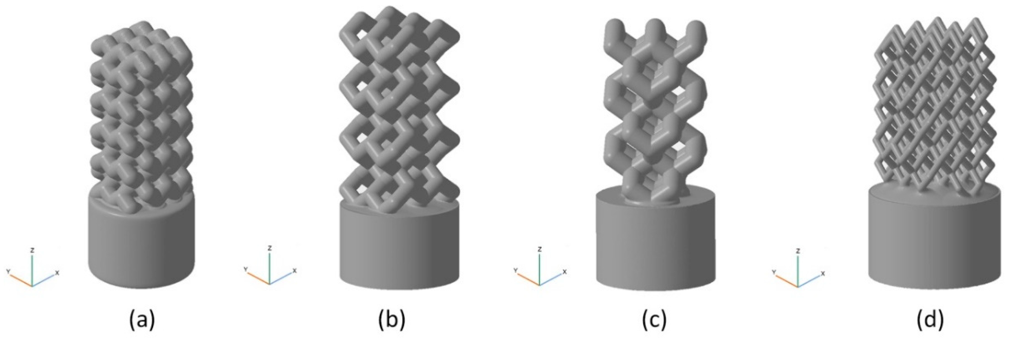
| BI001 Figure 5a | UC001 Figure 4a | 0.4 | L = 2.3, W = 2.3, H = 1.7 | Unit cell based on the tetrahedral diamond structure. | 3 | 3 | 5 |
| BI002 Figure 5b | UC002 Figure 4b | 0.7 | L = 1.6, W = 1.6, H = 2.3 | Built of UC001 unit cell by removing dangling ribs. | 2 | 2 | 4 |
| BI003 Figure 5c | UC003 Figure 4c | 0.7 | L = 3.5, W = 3.5, H = 3.8 | Built by replicating the UC002 unit cell along the X and Y axes by a factor of 2, with the offset along Z-axis by H/2, and along X axis by W/2. | 1 | 1 | 3 |
| BI004 Figure 5d | UC004 Figure 4d | 0.3 | L = 2.0, W = 2.0, H = 4.1 | Compression of the unit cell along X and Y axes by the factor of 2 | 3 | 3 | 3 |
| Model | Symvol for Rhino | STL |
|---|---|---|
| BI001 | 0.193 | 24.347 |
| BI002 | 0.128 | 39.920 |
| BI003 | 0.110 | 11.694 |
| BI004 | 0.141 | 24.180 |
| Model | With Account for the Cylindrical Base Plate (%) | Without Account for the Cylindrical Base Plate (%) |
|---|---|---|
| BI001 | 52.7 | 68.3 |
| BI002 | 53.0 | 70.5 |
| BI003 | 53.7 | 70.6 |
| BI004 | 63.9 | 84.4 |
| BI001 | BI002 | BI003 | BI004 | |
|---|---|---|---|---|
| Maximum load at a specimen, N | 817.5 | 279.9 | 93.0 | 221.6 |
| Effective compressive strength of the implant 1, MPa | 65.1 | 22.3 | 7.4 | 17.6 |
© 2020 by the authors. Licensee MDPI, Basel, Switzerland. This article is an open access article distributed under the terms and conditions of the Creative Commons Attribution (CC BY) license (http://creativecommons.org/licenses/by/4.0/).
Share and Cite
Safonov, A.; Maltsev, E.; Chugunov, S.; Tikhonov, A.; Konev, S.; Evlashin, S.; Popov, D.; Pasko, A.; Akhatov, I. Design and Fabrication of Complex-Shaped Ceramic Bone Implants via 3D Printing Based on Laser Stereolithography. Appl. Sci. 2020, 10, 7138. https://doi.org/10.3390/app10207138
Safonov A, Maltsev E, Chugunov S, Tikhonov A, Konev S, Evlashin S, Popov D, Pasko A, Akhatov I. Design and Fabrication of Complex-Shaped Ceramic Bone Implants via 3D Printing Based on Laser Stereolithography. Applied Sciences. 2020; 10(20):7138. https://doi.org/10.3390/app10207138
Chicago/Turabian StyleSafonov, Alexander, Evgenii Maltsev, Svyatoslav Chugunov, Andrey Tikhonov, Stepan Konev, Stanislav Evlashin, Dmitry Popov, Alexander Pasko, and Iskander Akhatov. 2020. "Design and Fabrication of Complex-Shaped Ceramic Bone Implants via 3D Printing Based on Laser Stereolithography" Applied Sciences 10, no. 20: 7138. https://doi.org/10.3390/app10207138
APA StyleSafonov, A., Maltsev, E., Chugunov, S., Tikhonov, A., Konev, S., Evlashin, S., Popov, D., Pasko, A., & Akhatov, I. (2020). Design and Fabrication of Complex-Shaped Ceramic Bone Implants via 3D Printing Based on Laser Stereolithography. Applied Sciences, 10(20), 7138. https://doi.org/10.3390/app10207138