Article

Additively Manufactured Parametric Universal Clip-System: An Open Source Approach for Aiding Personal Exposure Measurement in the Breathing Zone

1
Department of Mechanical Engineering, School of Engineering, Aalto University, 02150 Espoo, Finland
2
Finnish Institute of Occupational Health, FI-00032 Työterveyslaitos, Finland
3
Department of Electronics and Nanoengineering, School of Electrical Engineering, Aalto University, 02150 Espoo, Finland
4
Department of Materials Science & Engineering and Department of Electrical & Computer Engineering, Michigan Technological University, Houghton, MI 49931, USA
*
Author to whom correspondence should be addressed.
Appl. Sci. 2020, 10(19), 6671; https://doi.org/10.3390/app10196671
Submission received: 24 August 2020 / Revised: 14 September 2020 / Accepted: 22 September 2020 / Published: 24 September 2020
(This article belongs to the Special Issue Design for Additive Manufacturing: Methods and Tools)

Abstract

:

Featured Application

The customizable clip system opens new possibilities for occupational health professionals since the basic design can be altered to hold different kinds of samplers and tools. The solution is shared using an open source methodology to allow for distributed manufacturing of the free designs.

Abstract

Design for additive manufacturing is adopted to help solve problems inherent to attaching active personal sampler systems to workers for monitoring their breathing zone. A novel and parametric 3D printable clip system was designed with an open source Computer-aided design (CAD) system and was additively manufactured. The concept was first tested with a simple clip design, and when it was found to be functional, the ability of the innovative and open source design to be extended to other applications was demonstrated by designing another tooling system. The clip system was tested for mechanical stress test to establish a minimum lifetime of 5000 openings, a cleaning test, and a supply chain test. The designs were also tested three times in field conditions. The design cost and functionalities of the clip system were compared to commercial systems. This study presents an innovative custom-designed clip system that can aid in attaching different tools for personal exposure measurement to a worker’s harness without hindering the operation of the worker. The customizable clip system opens new possibilities for occupational health professionals since the basic design can be altered to hold different kinds of samplers and tools. The solution is shared using an open source methodology.

1. Introduction

The field of occupational health varies with the monitoring of working environment air quality being important in traditional fields ranging from mining to pig farming and new emerging areas such as 3D printing [1,2,3]. One of the important ways to assess worker’s personal exposure is to sample the breathing zone of the workers, which is conventionally defined as the area immediately surrounding a worker’s nose and mouth within 30 cm [4]. The purpose of air sampling in a worker’s breathing zone in the workplace is to identify and especially, quantify levels of impurities that worker is exposed during working hours. This is to ensure that workers are not exposed to dangerous levels of airborne contaminants such as dust, biological agents, toxic chemicals, or nanoparticles [5,6,7] and that the protective measures are adequate. With the onset of the COVID-19 pandemic, it has become increasingly important to maintain sufficient working and social distances to avoid the transmission of aerosol SARS-CoV-2 by inhalation [8]. Depending on the compounds, there are several commercial samplers available. For example, cyclone samplers can be utilized to measure respirable dust [4]. For such work, an active personal sampler system is a combination of sampler, which collects emissions from the air, an air pump, which pulls in air at a calibrated speed, and hose, which connects them.
The need to sample the air that workers breathe creates a challenge for attaching samplers, tubes, and air pumps to the workers without interfering with their work. In the worst case, poorly attached samplers can change workers maneuvers which can have an impact to the sample results. Often instructions for samplers include presuppositions of worker’s clothing/equipment such as “attach to the label of the worker’s coat”, “Clip pump to the worker’s belt”, and “put sampler to the pocket” [9]. This can lead to problems when worker’s clothing does not include these aforementioned items. The current state-of-the-art of sampler placement is a clamp with serrated edges, which can usually be attached to the clothing, but slippery fabrics of the work clothes and safety gear may cause problems with it. To enable definite sampler system placement, quite often some kind of harness or back bag system is used [4]. Worker’s differing sizes (heights, weights, etc.) and different types of worn safety equipment pose challenges for designing harness systems as the same equipment is routinely reused. Furthermore, additional attachment points are needed to ensure that the sampler system stays in the correct position. For example, the hose leading from the air pump needs to be tightly attached so it will not get caught and cause dangerous situations. Some samplers, such as cyclone samplers, have strict guidelines for staying in the correct position to function properly. The solutions for these problems are either custom fabricated components of high costs or on-the-spot solutions such as the use of duct tape, safety pins, and zip-ties, which are subject to appear as unprofessional; and in the worst case scenario, it can lead to poor data collection e.g., if the sampler becomes loose or poses a contamination risk for some industries e.g., food preparation.
Additive manufacturing (AM) has enabled the production of parts with unparalleled freedom of design, and it is widely adopted in the medical [10,11,12], dental [13], automotive [14], aerospace [15,16], and industrial machines [14,17,18] industries. It is mainly used to manufacture functional prototypes [14], rapid tooling [19,20], and end-use parts [17]. AM is also known as 3D printing, and in this study, the term “3D printing” is used for low cost desktop printers. Recently the widespread growth and accessibility of desktop 3D printers [13,21] brought on by the open source development of material extrusion 3D printing [22,23] offers a potential solution to this challenge. The principle of material extrusion is that a filament is extruded through a heated nozzle to create objects layer by layer [24]. 3D printing has been successfully used to make bespoke scientific tools in a number of disciplines for substantially lower costs than commercially available systems [25,26,27,28].
Designing for AM offers more geometric freedom, possibility to create easily customizable designs, new creative ways to manufacture instruments, decentralized manufacturing, and a range of material selection [12,18,29,30,31]. During the COVID-19 outbreak, AM has shown a great potential in mitigating the disruption in global medical and nonmedical supply chains [21].
In this study, the viability of using desktop 3D printing is analyzed to solve problems associated with attachment of sampler systems to workers for monitoring the breathing zone. A parametric and novel 3D printable clip system is designed, manufactured, and tested. The tests included a durability mechanical stress test to establish a minimum lifetime, a chemical solution test to ensure that the system can be appropriately cleaned, and a supply chain test to ensure occupational health professionals can use the digital files to customize and fabricate a custom system for their applications. The solution is shared using an open source methodology to allow for distributed manufacturing of the free designs, and the costs and functionalities of this system are compared to commercial systems. The open source methodology is a way to easily share designs and research [26]. The best practices of Open-source Hardware (OSHWA) contains guidelines for correctly sharing and properly documenting the studies [32]. The results are analyzed and discussed along with a description of future work.

2. Materials and Methods

User needs based on the problems of the current sampler systems and wishes for the improvements were determined in consultation with occupational specialists who use samplers on a daily and weekly basis. A universal clip system for personal exposure measurement in the breathing zone of workers was then designed as free and open source hardware [33] following a general procedure for designing Free and Open-source Scientific Hardware (FOSH) equipment [34].
The first challenge designing the universal clip system was to have a design, which is not reliant on the harness’s features and can be attached to any location on the harness. This would eliminate the need to alter the existing harness (e.g., no added hooks or holes). The second challenge was to find a design, which firmly stays in place. The third challenge was to make the design parametric, so that it can be easily altered to fit any harness on the market or can be further developed in the future. Fourth, the design should feature built in instructions so that users do not need to refer to external documentation to use it in the field. Finally, the design should also act as a universal base for different tooling options.
The design concept consists of two parts: (1) the sheath that holds the attachment features and contains the necessary instructions for correct orientation using arrows (Figure 1, middle/bottom left) and (2) the slider that locks the clip in place and also contains necessary tooling for example to hold the hose/sampler in place (Figure 1, middle/bottom right). The mechanism for the clip system works in the way that the harness is inserted inside the sheath by folding it. Then, the slider is slid to the sheath, which provides the necessary friction forces to hold the harness in between the two components in a single location and prevents sliding. The stopping mechanism inside the clip allows for the slider to level with the clip by clicking in place and stopping the sliding. This is done by installing click stoppers at the end of the clip. The release mechanism aids in unlocking the clip system by providing a sufficient amount of friction when a force is applied to it to uncouple the slider from the sheath by the user’s hand. This was accomplished by installing grippers to the slider.
The clip concept design was first developed for a simple hose holder clip, which can be used to keep hoses in place and avoid potentially dangerous loops. Previously, this was often prevented by taping the hose in place that resulted in sticky tape residue, which is inappropriate for some work environments (e.g., high ISO class cleanrooms [35]). After the hose holder clip was printed and the concept was found to be functional, the ability of the open source design to be adaptable to additional applications was demonstrated by extending the clip concept to another tooling system—the cyclone sampler holder to the slider.
The principles of fastening and releasing mechanisms, CAD design of the clip with hose holder tooling, and redesigned cyclone sampler tooling are shown in Figure 1.
Two parametric models were created using FreeCAD version 0.16, which is a free, open source software that is readily available over the internet [36]. The parametric nature of the models allows for making changes to the model with ease according to the used harness. The parameters associated with the clip system that is equipped with a hose holder are shown in Figure 2a,b. Parameters that can be modified are harness width, harness thickness, clip thickness, clip height, and assembly print clearance, which is dependent on the used 3D printer. Three variants of the clip system with varying parameters are presented in Figure 2c, however, the most probable changed parameters would be harness width and thickness. In the hose holder clip FreeCAD design, the hose diameter including the clearance is also one parameter that can be changed according to the used hose. The full designs are available on the Open Science Framework (OSF) for downloading [37]. The file formats available are STL (the standard file format for AM) and FCStd (FreeCADs file format, which enables parameter changing). Printing instructions can be found in Appendix A.
The design of the clip system was modelled according to the Fused Deposition Modeling (FDM) Design Guidelines [38] that ensured the ultimate tensile strength of at least 33 MPa according to the datasheet of ABS (acrylonitrile butadiene styrene) material that was used for printing [39]. It should be noted that FDM is a trademark registered by Stratasys and thus, a subset of material extrusion (ME). Any material extrusion-based 3D printing system capable of appropriate polymers (e.g., ABS, PC, etc.) can be used to fabricate the design. The uPrint SE Plus ME printer from Stratasys was used to print the clips with ivory ABS filament. Minimum layer thickness and assembly clearance was set as 0.254 mm. The parts were printed in “upright position” for maximum strength in the X-Y planes following guidelines [38]. The printing times were 2 h 44 min for the hose holder clip and 4 h 13 min for the redesigned cyclone sampler holder clip. For the purpose of testing the clip systems, a prototype harness was fabricated and used for testing.
Due to the nature of the measuring done in different environments from food industry to mining industry, cleaning the clip systems between different environments is important to avoid contamination. The hose holder clip was cleaned by wiping and immersing in an 80% ethanol–water solution. One cleaning cycle lasted for approximately 55 s, which was reiterated 50 times.
The mechanical properties of additively manufactured ABS are well established that range from 21 to 39 MPa in tensile and 38 to 41 MPa in compressive strength [40,41,42,43,44,45,46]. Low-cost desktop printers have been used to produce parts with these proprieties reliably for mechanically taxing applications from bicycled parts [47] to surgical tools [48]. The known issue of additively manufactured components is the lower tensile stress values in the Z-direction (upwards). The designs of the tensile and/or compressive specimens in the aforementioned literature ensured that no stress concentration was built up around the fillet of the specimens due to raster termination. This was accomplished either by completely removing the fillet and adapting a flat rectangular specimen according to ASTM D3039 [49] and/or improvising the specimens of ASTM D638 [50]. Likewise, the current design of the clip system ensured that no rasters were terminated at edges of the clip system that were loaded with the most stress during usage. Furthermore, fatigue strength of ABS is recorded as 17.8 MPa with 1.9 × 10⁴ cycles [51] and 40% of the ultimate tensile strength in the order of thousands of cycles [52]. The stresses induced in the clip system during fastening or releasing can be considered as negligible due to the nature of light weight tooling that is used for this study.
Nevertheless, after the cleaning test, the clip system was then put through a durability test similar to those on medical diagnostic equipment [53] consisting of mechanical testing of the clip system through sliding the slider to sheath on and off repeatedly when it was attached to a harness. This procedure was executed 5000 times. This would correlate to 500 clicks annually and is an estimated use case for a 10-year lifecycle if two measurements per week are made. This durability testing consisted of an expected failure analysis at the system designs weakest point. In this failure testing, the clip system was subjected to elastic deformation similar to what would be expected in the application of attaching the system to the harness, but to a greater extent as in this case it was repeated immediately allowing for heat to be generated by the friction of repetitions. The heat generated in the testing was not near notable values. In addition of mechanical friction testing, the clip system was tested by putting it on and off a harness for 500 times.
Before the field testing, both the hose holder clip and cyclone sampler clip were subjected to lead user testing. This test covered ease of use and aesthetics of these clips compared to the traditional systems. During the field testing, test subjects were interviewed to provide feedback concerning the functionality and ergonomics of the clips. Two occupational specialists placed the harness on and used the previous systems of attaching the hose and cyclone sampler. These previous solutions were a custom made metal hose holder and original cyclone sampler holder with a serrated edge clamp. After testing the previous solutions, they tested prototype harness and placed the cyclone sampler with the redesigned clip into it and used the hose holder clip to attach the hose. The clips were also tested if they could be used with commercial harnesses as well as the prototype harness.
Field testing of the hose holder was carried out in three different measurements and workplaces in May, June, and October 2018. Duration of the first measurement was 20 min, and similarly, it was 6 h for the second, and 5 h for the third measurement. During the first measurement, the clip as well as prototype harness was attached to an operator in an industrial workplace. Volatile chemical compounds were measured. The work was partly physical but also included driving a forklift. The hose holder kept the sampling hose attached to a harness and an air pump, although plastic clamps of the prototype harness released during the measurements. A second measurement was also done in an industrial workplace where maintenance worker’s exposure to inhalable dust was measured. The worker had hose holder clip(s) with original harnesses. In the third measurement, the cyclone sampler attached to the original harness was used in a machine workshop during welding. A respirable dust was measured from the breathing zone for manganese analysis to evaluate worker’s exposure. A hose holder clip was also used. After every measurement, the clip holders were detached from the harness and cleaned according to a cleaning test.
To simulate the situation where environmental experts would decide on their own clip needs, generate correct files, and send the files to be printed in (e.g., using 3D printing services like 3D Hubs, 3DSD, etc.) or print their own systems using low-cost 3D printers, a test was designed. The test occupational specialist/possible end user with no CAD experience was given a link to the files, the FreeCAD software, and instructions for printing. They downloaded the hose holder clip files (FCStd) and opened them in the downloaded FreeCAD. Then, they decided which harness width they wished to use and changed it in the parametric model to generate correct 3D data. Then, they sent the STL data to be printed. There were three cases, in the first case, Aalto University acted as a service provider and printed both clip systems with an industrial level printer (uPrint SE Plus) and printed the hose holder clip with a low-cost printer (Lulzbot Mini). In the second case, a test person’s organization, Finnish Institute of Occupational Health (FIOH), had their own in-house printer (Uprint SE Plus) and they tested the printing of their own clips as well. FIOH acted as a pilot organization for this study. Thirdly, an STL file was generated and uploaded to four internet 3D printing service providers to get cost and lead time quotations. These service providers were 3D Hubs [54,55,56,57].
The systems were massed with a digital scale (Mettler AE 200 +/− 0.0001 g). The material cost of each systems was calculated by multiplying the aggregate of the component weight by the cost of ABS per gram ($19.99/kg Amazon) for Lulzbot Mini and by the cost of ABSplus + SR30 soluble support per gram (317.25 €/kg + 288.84 €/kg +VAT) for uPrint SE Plus, as previous work has shown that the electrical consumption costs are not necessary [58]. Both the hose holder clip and cyclone sampler holder clip were printed with harness width of 30 mm.
Operating costs per hour were calculated with an assumption of price of the machine, which is amortized in certain amount of years during the expected usage. Price of the machine was 16,000 €, amortizing time was 3 years with an expected usage of 1500 h/year for uPrint SE Plus. Similarly, the price was 1100 € assuming an amortization time of 3 years with 500 h/year of usage for Lulzbot Mini.

3. Results

The hose holder parametric clip systems were additively manufactured successfully through uPrint SE Plus (Stratasys, Eden Prairie, MN, USA) and Lulzbot Mini (Aleph Objects Inc., Loveland, CO, USA) in Aalto University and with uPrint SE Plus in pilot organization. Further, cyclone sampler holder clips were printed with uPrint SE Plus in both locations. The hose holder clip was printed with two different harness widths (25 and 30 mm) to prove that the parametric design functioned as planned.
Figure 3 showcases both old traditional and new components along with assembled systems on a prototype harness. Firstly, Figure 3 shows four printed hose holder assemblies in the printing bed with support structures that display recommended printing orientation (a), and instructions on the way in which the slider should slide in the sheath when in the harness (b). Figure 3 also shows the assembled cyclone sampler holder with additively manufactured holder (d), and comparison of new ABS hose holder and traditional metal version, which was attached with green tape (c). Further, Figure 3 shows the blue hose holder clip, which was printed with low-cost 3D printer (f), and also the black hose holder and cyclone sampler holder clip, which were printed as part of supply chain testing in FIOH (e). Finally, Figure 3 demonstrates both the cyclone sampler and hose holder in practice, with the new prototype harness from the front (g) and back (h).
Cleaning test had no significant effect on the test clip, as was expected based on previous work that has shown that additively manufactured ABS is chemically compatible with ethanol–water solutions as well as hydrochloric acid (HCl, 37%), ammonia (NH3, 25%), hydrogen peroxide (H2O2, 30%), phosphoric acid (H3PO4, 85%), and nitric acid (HNO3, 69%) [59].
In the expected mechanical failure analysis, the parametric clip system passed a series of altogether 5000 openings and closings without any significant plastic deformation that would inhibit the proper use of the device over a 10-year lifetime. The deformation was too minor to have an impact on the functional integrity of the clip system and was barely noticeable with a naked eye.
Lead user feedback gave the clips good results. Clips could be used with commercially purchased harnesses as easily as with a prototype harness as long as they were the correct width and thickness. Testing subjects gave feedback for both the hose holder clip and cyclone sampler holder clip. They found ergonomics of the new clips to be the same as the traditional design or better. In functionality, they preferred the new clips. The new clip design did not require tape to secure certain placement, which was found to be excellent. Aesthetically, both testers found the new clips to be more professional looking than the tape set-up. In usability, one of them preferred the old attachment of the cyclone sampler, because it had involved less steps for placing it on. They then admitted that the new cyclone sampler clip system gave more secure grip and would less likely be dislocated than serrated clamps. Otherwise in usability, new clips were preferred but difficult to attach in field circumstances when there is usually a hurry.
The hose holder clips performed adequately in field tests. Zip-ties were used to ensure that no accidental dislocation would happen as the field tests were done in real life sampling situations where it is imperative that sampling is done correctly in one go. These zip-ties did not interfere with working of clips. The occupational specialist was satisfied with performance of the clips and speculated that when they get used to using clips, the zip-ties might be unnecessary. All the clips performed well in the active measuring situation. After the first field test, one of the hose holder clip’s prongs were broken during transportation in a bag, presumably because something heavy was placed on top of it. After the third test, one of the hose holder clip’s “prongs” broke during removal of the hose. All other clips were a whole and no visible cracks were observed.
The cyclone sampler holder clip test was also successful. The occupational specialist noted that the cyclone sampler clip’s hold had been very secure. After the field tests, the occupational specialist’s comments about the clips were enthusiastic and several suggestions of future work were mentioned such as longer hose holder, double hose holder, and parametric markings to the clips to express which width and thickness they are meant to have. Reinforcing of the hose holder clip’s “prongs” was also suggested including changing the material to a more flexible one.
The supply chain tests showed that a person with no background in AM or experience in CAD designs can change an open source parametric model and generate the needed model with only links and basic written instructions. The occupational specialist had slight problems with FreeCAD, which were already known and are described in Appendix A. Upon following the instructions described in Appendix A, the user was able conveniently solve the Kernel related problems of the open source software. Subsequently, the user was able to generate the necessary models for AM and was able to send it to Aalto University and a pilot organization for production.
The experimental average mass of the hose holder clip system was 13.00 g, which resulted in a range of costs for the components detailed in Table 1. Clip variants 1 and 3 were printed with uPrint Plus SE, and clip variant 2 with Lulzbot mini. Clip variants 1 and 2 were hose holder clips and variant 3 is a cyclone sampler holder clip. All clip variants were designed for 30 mm harness width. The operating cost was calculated, and total price of the clip was obtained by adding together the material cost and operating cost.
This amounts to savings per replica of 23.36 € for Amazon generic material printed with Lulzbot Mini and 9.9 € for proprietary material printed with uPrint SE Plus, when the price of the original hose holder clip purchased was estimated to be 25 €. These are the cases for in-house production.
The hose holder clip was also uploaded to four different 3D printing service providers via internet and quotes from 21.94 € upwards were received. This is most probable use case for acquiring the clips, because the AM production knowledge and printers are not yet common enough.

4. Discussion

Sampling in the worker’s breathing zone is one of the most applicable way to assess worker’s personal exposure. To get correct positioning in the breathing zone, both commercial and custom-made harnesses may be used. Clamps, tapes, and zip-ties are currently used to attach sampler systems to the harness, creating issues with secureness of the hold, unprofessional looks, and hygienic problems. Designing specifically for AM and 3D printing, the novel design of a universal clip system will help create an aesthetically professional and securely attachable sampler. In this study, such a clip system was designed and tested, first with the hose holder clip and then, the cyclone sampler clip. Both clip systems performed well, although strengthening of hose holder’s “prongs” is suggested. The field test showed that especially the cyclone sampler clip is ready for real life sampling situations. For the occupational specialists, a short learning curve is needed before use of clips is instinctual. However, this can be compared with the initial introduction of conventionally used attachment gear and can be circumvented through the supporting documents provided in Appendix A. Field tests also showed that it is important to have back-up clips in case of surprises.
Parametric design of the clip can ensure that the fit of the clip can be made to fit any harness as long as width and thickness of the harness is known. Depending on the 3D printer, some adjustments may be needed to find the correct process parameters which is supported by the parametric settings, in particular the clearance.
The open source files of the design and availability of 3D printing mean that the clip is obtainable to any person, who needs these kind of clip systems. 3D printing also enables the selection of a range of materials and colors.
Using affordable 3D printers means that the costs of the clip systems stay low and the open source nature of the clip system will be able to accommodate customization with minimal additional costs. Therefore, the cost comparison made only on a material level is justified; purchased traditionally manufactured components are compared to the direct material and operating costs of 3D printing.
This customization of the clip system could easily be extended to other tooling options as well since the basic design can be altered to hold other kinds of samplers and tools. To which areas the clip system design can be extended, and what are the limitations, is work for the future studies.
The cost savings shown in Table 1 are the materials and 3D printer operating costs only and they do account for any labor costs. This is a valid assumption as the time needed to customize the system for specific users is comparable (and perhaps shorter) to the time needed to shop for the correct size of the system online. 3D printers do not need to be monitored during use. Thus, the time to print on any of the systems, although hours, is irrelevant as only the time to set up a print is taken into consideration, which is approximately equivalent to ordering a commercial product online. The time to remove the supports, which is less than 10 min for the devices, can be compared to the time it would take to accept delivery of a package and unpack it. Lastly, once all of the components are gathered, they must be assembled. Assembling the complete system takes a similar amount of time to commercial systems. Finally, it is important to point out the life cycle cost advantages of this system. As all the files are shared, regardless of the source of failure of any of the components, the system is easily repaired from readily available components (e.g., reprint a broken plastic component). This ease of repair and upgrading is simply not available for all the commercial systems, which would demand the purchasing of replacement devices. Thus, the value of the open source additively manufactured universal clip system for personal exposure measurement in the breathing zone of workers can be considered higher than the commercial functional equivalent, even though the open source tool costs less money to build upfront.

5. Conclusions

This study successfully described the development, design, and testing of a novel 3D printable open source clip system for attaching personal exposure samplers to harnesses. This clip system was extended from a simple hose holder clip to a redesigned cyclone sampler holder. The hose holder clip system proved to be 3D printable with affordable desktop 3D printers, which gives considerable savings compared to custom solutions used before and allows for distributed manufacturing through free designs. The clip system also improved functionality and security of sampler placement. The testing of the clip system showed minimum of 10 years of lifetime.
Secure and user-friendly research instrumentation is essential to ensure consistency and reliability of personal exposure measurements. The open source clip system described here could serve as a reference design for future improvements. The design allows easy customization and modification for other types of instruments. Modifications to the reference design are expected to be faster and more cost efficient than completely new untested clip designs.

Author Contributions

Conceptualization, K.K. and J.S.A.; methodology, K.K. and J.S.A.; validation, K.K., J.S.A. and A.K.; investigation, K.K., J.S.A. and A.K.; resources, M.S., R.B., A.-K.V. and J.P.; data curation, K.K. and J.S.A.; writing—original draft preparation, K.K., J.S.A. and J.M.P.; writing—review and editing, K.K., J.S.A., A.K., M.S., R.B., A.-K.V., J.P. and J.M.P.; visualization, K.K. and J.S.A.; supervision, A.-K.V., J.P. and J.M.P.; All authors have read and agreed to the published version of the manuscript.

Funding

This research received no external funding.

Acknowledgments

This work was supported by Aalto University, Finnish Institute of Occupational Health and Fulbright Finland. The authors would like to acknowledge helpful discussions with Marika Loikala.

Conflicts of Interest

The authors declare no conflict of interest.

Appendix A

Printing instructions
Link to the clip system files can be found osf.io/6u3zr.
Hose holder clip and cyclone sampler holder clip can be printed with the STL files provided in the above link using any ISO/ASTM Standardized Additive Manufacturing Method. These STL files are for harness, which width is 30 mm and thickness is 1.4 mm. The printing materials are recommended to be polymers.
To create new STL files from parametric models, use the following instructions:
  • Download the open source FreeCAD software from https://www.freecadweb.org/.
  • Download the model files provided in the link above.
  • Open the necessary FreeCAD [.FCstd] file using open source FreeCad Software.
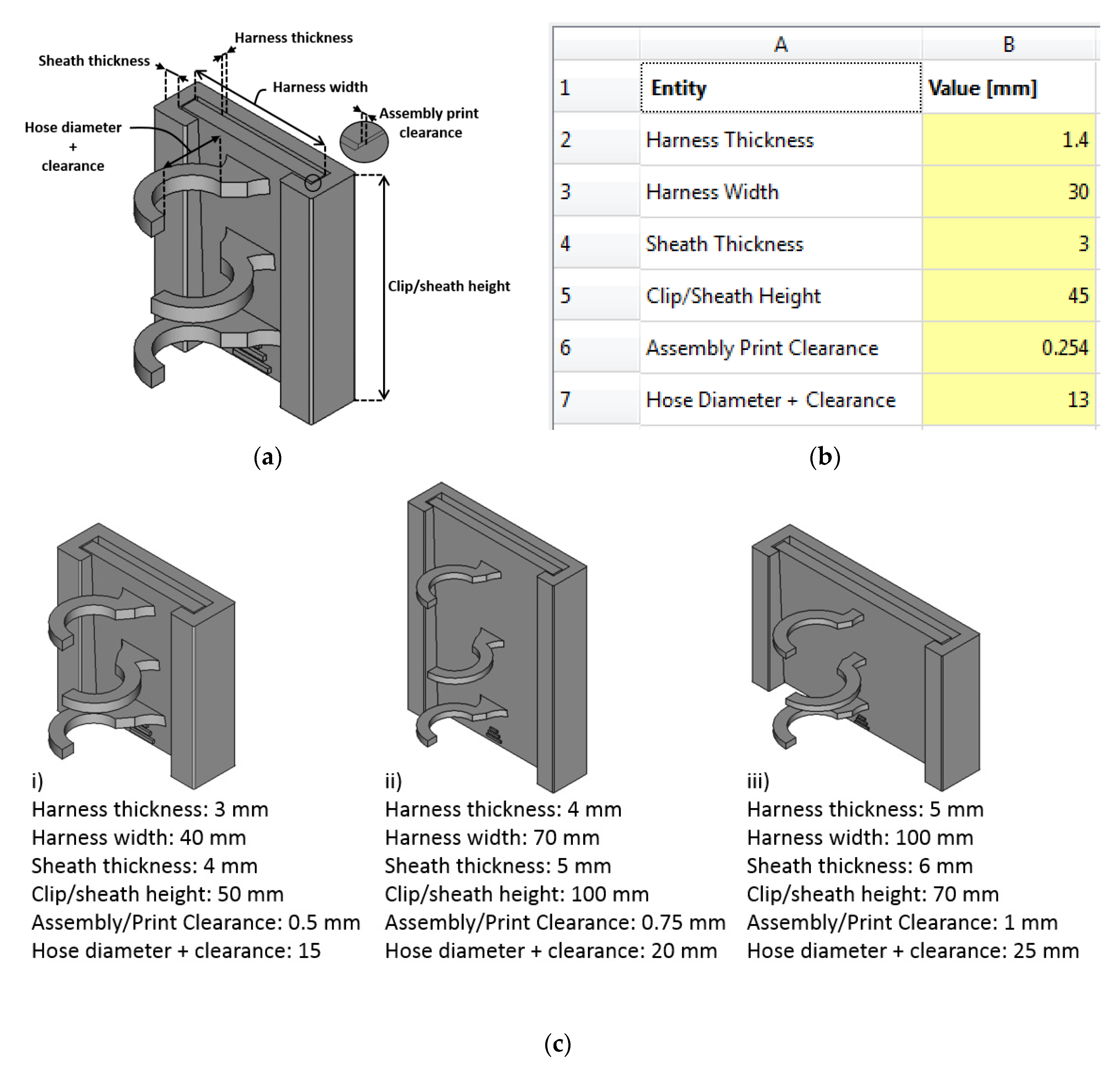
  • To access parameters, double click the spreadsheet (left, under Model and labels and Attributes page). Depending of the printer, you may need to adjust assembly clearance and/or harness thickness.
  • Change the required parameters in the Spreadsheet. Please note that regeneration may take some time depending on your hardware specs.‘*’
  • Export model as STL to print the model. (Files-> Export). Remember to click the model to activate it before exporting.
  • Use STL file to print the model with (material extrusion) 3D printer. Depending on the printer, you may need to use the brim command to avoid bending. You may also consider printing the hose holder clip arrow downward to ensure good detail of the stopper mechanism.
  • Remove the support structures. They can be removed by hand or with a sharp knife.
‘*’Please note that Boolean operations can fail upon regeneration because of the CAD kernel of the open source software. Always use the latest version of the software and try different values of the parametric parameters or delete the Boolean operations to overcome this limitation. Likewise, the fillet operation(s) may fail upon regeneration as well. Remove fillets and redeploy the necessary operation(s) after regeneration to overcome these limitations.
Using the clip with the harness
  • Remove slider from sheath.
  • Place the harness in the slot of the sheath through its open side. The open side will be the front of the harness and the back (arrow) side will be against the person.
  • Slide the sheath on the harness to the needed position. Please note that arrow at the back of the sheath should be pointing up. When using in horizontal harness placement, that arrow points to the direction where slider will be inserted from.
  • Insert the slider with the release mechanism first to the sheath.
  • Push the slider until it clicks. It should be same level as the sheath.
  • Push the release mechanism (segmented arrowhead) upwards to unlock the clip and to separate the components. Please do not push the hose holder or any other parts of tooling.
  • Remove sheath from the harness.

References

  1. Vinson, R.; Volkwein, J.; McWilliams, L. Determining the Spatial Variability of Personal Sampler Inlet Locations. J. Occup. Environ. Hyg. 2007, 4, 708–714. [Google Scholar] [CrossRef]
  2. Wang, C.-H.; Chen, B.T.; Han, B.-C.; Liu, A.C.-Y.; Hung, P.-C.; Chen, C.-Y.; Chao, H.J. Field Evaluation of Personal Sampling Methods for Multiple Bioaerosols. PLoS ONE 2015, 10, e0120308. [Google Scholar] [CrossRef] [PubMed]
  3. Stephens, B.; Azimi, P.; El Orch, Z.; Ramos, T. Ultrafine particle emissions from desktop 3D printers. Atmos. Environ. 2013, 79, 334–339. [Google Scholar] [CrossRef]
  4. Ruzer, L.; Harley, N. Aerosols Handbook; CRC Press: Boca Raton, FL, USA, 2013; ISBN 9781439855195. [Google Scholar]
  5. Lidén, G. Evaluation of the SKC Personal Respirable Dust Sampling Cyclone. Appl. Occup. Environ. Hyg. 1993, 8, 178–190. [Google Scholar] [CrossRef]
  6. Haig, C.W.; Mackay, W.G.; Walker, J.T.; Williams, C. Bioaerosol sampling: Sampling mechanisms, bioefficiency and field studies. J. Hosp. Infect. 2016, 93, 242–255. [Google Scholar] [CrossRef] [PubMed]
  7. Asbach, C.; Alexander, C.; Clavaguera, S.; Dahmann, D.; Dozol, H.; Faure, B.; Fierz, M.; Fontana, L.; Iavicoli, I.; Kaminski, H.; et al. Review of measurement techniques and methods for assessing personal exposure to airborne nanomaterials in workplaces. Sci. Total Environ. 2017, 603–604, 793–806. [Google Scholar] [CrossRef]
  8. Vuorinen, V.; Aarnio, M.; Alava, M.; Alopaeus, V.; Atanasova, N.; Auvinen, M.; Balasubramanian, N.; Bordbar, H.; Erästö, P.; Grande, R.; et al. Modelling aerosol transport and virus exposure with numerical simulations in relation to SARS-CoV-2 transmission by inhalation indoors. Saf. Sci. 2020, 130, 104866. [Google Scholar] [CrossRef]
  9. National Institute for Occupational Safety Health Division of Physical Sciences Engineering. Manual of Analytical Methods; DHHS (NIOSH) Publication: Washington, DC, USA, 1994. [Google Scholar]
  10. Akmal, J.S.; Salmi, M.; Hemming, B.; Teir, L.; Suomalainen, A.; Kortesniemi, M.; Partanen, J.; Lassila, A. Cumulative Inaccuracies in Implementation of Additive Manufacturing Through Medical Imaging, 3D Thresholding, and 3D Modeling: A Case Study for an End-Use Implant. Appl. Sci. 2020, 10, 2968. [Google Scholar] [CrossRef]
  11. Tuomi, J.; Paloheimo, K.; Björkstrand, R.; Salmi, M.; Paloheimo, M.; Mäkitie, A.A. Medical applications of rapid prototyping—From applications to classification. Innov. Dev. Des. Manuf. 2010, 701–704. [Google Scholar] [CrossRef]
  12. Akmal, J.; Salmi, M.; Mäkitie, A.; Björkstrand, R.; Partanen, J. Implementation of Industrial Additive Manufacturing: Intelligent Implants and Drug Delivery Systems. J. Funct. Biomater. 2018, 9, 41. [Google Scholar] [CrossRef] [Green Version]
  13. Salmi, M.; Tuomi, J.; Sirkkanen, R.; Ingman, T.; Makitie, A. Rapid tooling method for soft customized removable oral appliances. Open Dent. J. 2012, 6, 85–89. [Google Scholar] [CrossRef] [PubMed]
  14. Wohlers, T. Wohlers Report 2020; Wohlers Associates, Inc.: Fort Collins, CO, USA, 2020. [Google Scholar]
  15. Khajavi, S.H.; Partanen, J.; Holmström, J. Additive manufacturing in the spare parts supply chain. Comput. Ind. 2014, 65, 50–63. [Google Scholar] [CrossRef]
  16. Totin, A.; Macdonald, E.; Conner, B. Additive manufacturing for aerospace maintenance and sustainment. DSIAC J. 2019, 6, 4–11. [Google Scholar]
  17. Salmi, M.; Partanen, J.; Tuomi, J.; Chekurov, S.; Björkstrand, R.; Huotilainen, E.; Kukko, K.; Kretzschmar, N.; Akmal, J.; Jalava, K.; et al. Digital Spare Parts. Aalto University. 2018. Available online: http://urn.fi/URN:ISBN:978-952-60-3746-2 (accessed on 22 September 2020).
  18. Ullah, R.; Akmal, J.S.; Laakso SV, A.; Niemi, E. Anisotropy of additively manufactured 18Ni-300 maraging steel: Threads and surface characteristics. Procedia CIRP 2020, 93C, 66–76. [Google Scholar] [CrossRef]
  19. Jalava, K.; Salmi, M.; Kukko, K.; Orkas, J. Multi-scale topologically optimized components made by casting and additive manufacturing. In Proceedings of the 73rd World Foundry Congress, Congress Proceedings, Krakow, Poland, 23–27 September 2018; pp. 141–142. [Google Scholar]
  20. Akmal, J. Digital Unique Component Manufacturing Through Direct and Indirect Additive Manufacturing. Aalto University 2017. Available online: http://urn.fi/URN:NBN:fi:aalto-201710307355 (accessed on 22 September 2020).
  21. Salmi, M.; Akmal, J.S.; Pei, E.; Wolff, J.; Jaribion, A.; Khajavi, S.H. 3D Printing in COVID-19: Productivity Estimation of the Most Promising Open Source Solutions in Emergency Situations. Appl. Sci. 2020, 10, 4004. [Google Scholar] [CrossRef]
  22. Jones, R.; Haufe, P.; Sells, E.; Iravani, P.; Olliver, V.; Palmer, C.; Bowyer, A. RepRap: The replicating rapid prototyper. Robotica 2011, 29, 177–191. [Google Scholar] [CrossRef] [Green Version]
  23. Bowyer, A. 3D printing and humanity’s first imperfect replicator. 3d Print Addit. Manuf. 2014, 1, 4–5. [Google Scholar] [CrossRef]
  24. ISO/TC 261 ISO/ASTM 52900:2015(E). Additive Manufacturing-General Principles-Terminology, 2nd ed.; ISO/ASTM International: Vernier, Switzerland, 2015. [Google Scholar]
  25. Pearce, J.M. Building Research Equipment with Free, Open-Source Hardware. Science 2012, 337, 1303–1304. [Google Scholar] [CrossRef]
  26. Pearce, J.M. Open-Source Lab.: How to Build. Your Own Hardware and Reduce Research Costs; Elsevier: Amsterdam, The Netherlands, 2014. [Google Scholar]
  27. Baden, T.; Chagas, A.M.; Gage, G.; Marzullo, T.; Prieto-Godino, L.L.; Euler, T. Open labware: 3-D printing your own lab equipment. PloS Biol. 2015, 13, e1002086. [Google Scholar] [CrossRef]
  28. Coakley, M.; Hurt, D.E. 3D printing in the laboratory: Maximize time and funds with customized and open-source labware. J. Lab. Autom. 2016, 21, 489–495. [Google Scholar] [CrossRef] [Green Version]
  29. Khajavi, S.; Holmström, J.; Partanen, J. Additive manufacturing in the spare parts supply chain: Hub configuration and technology maturity. Rapid Prototype J. 2018, 65, 50–63. [Google Scholar] [CrossRef] [Green Version]
  30. Chekurov, S.; Kajaste, J.; Saari, K.; Kauranne, H.; Pietola, M.; Partanen, J. Additively manufactured high-performance counterflow heat exchanger. Prog. Addit. Manuf. 2019, 4, 55–61. [Google Scholar] [CrossRef] [Green Version]
  31. Thompson, M.K.; Moroni, G.; Vaneker, T.; Fadel, G.; Campbell, R.I.; Gibson, I.; Bernard, A.; Schulz, J.; Graf, P.; Ahuja, B.; et al. Design for Additive Manufacturing: Trends, opportunities, considerations, and constraints. Cirp. Ann. 2016, 65, 737–760. [Google Scholar] [CrossRef]
  32. Best Practices for Open-Source Hardware 1.0. Available online: https://www.oshwa.org/sharing-bestpractices/ (accessed on 10 September 2020).
  33. Gibb, A. Building Open Source Hardware: DIY Manufacturing for Hackers and Makers; Pearson Education: London, UK, 2014. [Google Scholar]
  34. Oberloier, S.; Pearce, J.M. General Design Procedure for Free and Open-Source Hardware for Scientific Equipment. Designs 2017, 2, 2. [Google Scholar] [CrossRef] [Green Version]
  35. ISO. ISO 14644-1:2015; Cleanrooms and Associated Controlled Environments. Part. 1: Classification of Air Cleanliness By Particle Concentration; ISO: Geneva, Switzerland, 2015. [Google Scholar]
  36. FreeCAD: An Open-Source Parametric 3D CAD Modeler. Available online: https://www.freecadweb.org/ (accessed on 24 May 2018).
  37. Akmal, J.S.; Kukko, K.; Pearce, J.M. Additively Manufactured Parametric Universal-Clip-System. 2019. Available online: https://osf.io/6u3zr/ (accessed on 22 September 2020).
  38. Stratasys Direct, Inc. Fused Deposition Modeling (FDM) Design Guidelines. 2015. Available online: https://www.stratasysdirect.com/resources/design-guidelines/fused-deposition-modeling (accessed on 22 September 2020).
  39. Stratasys Direct, Inc. ABSplus-P430: Production-Grade Thermoplastic for 3D Printers. 2017. Available online: https://www.stratasys.com/materials/search/absplus (accessed on 22 September 2020).
  40. Ahn, S.-H.; Montero, M.; Odell, D.; Roundy, S.; Wright, P.K. Anisotropic material properties of fused deposition modeling ABS. Rapid Prototype J. 2002, 8, 248–257. [Google Scholar] [CrossRef] [Green Version]
  41. Croccolo, D.; De Agostinis, M.; Olmi, G. Experimental characterization and analytical modelling of the mechanical behaviour of fused deposition processed parts made of ABS-M30. Comput. Mater. Sci. 2013, 79, 506–518. [Google Scholar] [CrossRef]
  42. Tymrak, B.M.; Kreiger, M.; Pearce, J.M. Mechanical properties of components fabricated with open-source 3-D printers under realistic environmental conditions. Mater. Des. 2014, 58, 242–246. [Google Scholar] [CrossRef]
  43. Letcher, T.; Rankouhi, B.; Javadpour, S. Experimental study of mechanical properties of additively manufactured ABS plastic as a function of layer parameters. In Proceedings of the ASME International Mechanical Engineering Congress and Exposition, Houston, TX, USA, 13–19 November 2015; Volume 57359, p. V02AT02A018. [Google Scholar]
  44. Rankouhi, B.; Javadpour, S.; Delfanian, F.; Letcher, T. Failure analysis and mechanical characterization of 3D printed ABS with respect to layer thickness and orientation. J. Fail. Anal. Prev. 2016, 16, 467–481. [Google Scholar] [CrossRef]
  45. Tanikella, N.G.; Wittbrodt, B.; Pearce, J.M. Tensile strength of commercial polymer materials for fused filament fabrication 3D printing. Addit. Manuf. 2017, 15, 40–47. [Google Scholar] [CrossRef] [Green Version]
  46. Lee, C.S.; Kim, S.G.; Kim, H.J.; Ahn, S.H. Measurement of anisotropic compressive strength of rapid prototyping parts. J. Mater. Process. Technol. 2007, 187–188, 627–630. [Google Scholar] [CrossRef]
  47. Tanikella, N.G.; Savonen, B.; Gershenson, J.; Pearce, J.M. Viability of distributed manufacturing of bicycle components with 3-D printing: CEN standardized polylactic acid pedal testing. J. Hum. Eng. 2017, 5, 1. [Google Scholar]
  48. Rankin, T.M.; Giovinco, N.A.; Cucher, D.J.; Watts, G.; Hurwitz, B.; Armstrong, D.G. Three-dimensional printing surgical instruments: Are we there yet? J. Surg. Res. 2014, 189, 193–197. [Google Scholar] [CrossRef] [PubMed] [Green Version]
  49. ASTM. ASTM D3039-76, Test. Method for Tensile Properties of Polymer Matrix Composite Materials; ASTM: West Conshohocken, PA, USA, 1976. [Google Scholar]
  50. ASTM. ASTM D638-97, Test. Method for Tensile Properties of Plastics; ASTM: West Conshohocken, PA, USA, 1997. [Google Scholar]
  51. Padzi, M.M.; Bazin, M.M.; Muhamad, W.M.W. Fatigue Characteristics of 3D Printed Acrylonitrile Butadiene Styrene (ABS). IOP Seri. Mater. Sci. Eng. 2017, 269, 012060. [Google Scholar] [CrossRef]
  52. Lee, J.; Huang, A. Fatigue analysis of FDM materials. Rapid Prototype J. 2013, 19, 291–299. [Google Scholar] [CrossRef]
  53. Michaels, R.E.; Pearce, J.M. 3-D printing open-source click-MUAC bands for identification of malnutrition. Public Health Nutr. 2017, 20, 2063–2066. [Google Scholar] [CrossRef] [Green Version]
  54. 3D HUBS: Network of Manufacturing Hubs. Available online: https://www.3dhubs.com/ (accessed on 15 March 2019).
  55. CraftCloud: Service Provider. Available online: https://craftcloud.all3dp.com/ (accessed on 15 March 2019).
  56. SD3D: Service Provider. Available online: https://www.sd3d.com/ (accessed on 15 March 2019).
  57. iMaterialise: Service Provider. Available online: https://i.materialise.com/ (accessed on 8 March 2019).
  58. Wittbrodt, B.T.; Glover, A.G.; Laureto, J.; Anzalone, G.C.; Oppliger, D.; Irwin, J.L.; Pearce, J.M. Life-cycle economic analysis of distributed manufacturing with open-source 3-D printers. Mechatronics 2013, 23, 713–726. [Google Scholar] [CrossRef] [Green Version]
  59. Heikkinen IT, S.; Kauppinen, C.; Liu, Z.; Asikainen, S.M.; Spoljaric, S.; Seppälä, J.V.; Savin, H.; Pearce, J.M. Chemical Compatibility of Fused Filament Fabrication -based 3-D Printed Components with Solutions Commonly Used in Semiconductor Wet Processing. Addit. Manuf. 2018, 23, 99–107. [Google Scholar] [CrossRef] [Green Version]
Figure 1. FreeCAD renderings of the fastening mechanism on the sheath (top left), releasing mechanism on the slider (top right), clip system from the back (middle left), clip system with hose holder tool from the front (middle right), redesigned clip system for the cyclone sampler from the back (bottom left), and redesigned clip system for the cyclone sampler from the front (bottom right).
Applsci 10 06671 g001
Figure 2. (a) The 5 + 1 input parameters of the parametric clip system equipped with a hose holder; (b) the 5+1 input parameters spreadsheet of the parametric clip system equipped with a hose holder; (c) three variants of the parametric clip system equipped with a hose holder.
Applsci 10 06671 g002
Figure 3. (a) Five hose holders with support structures in the printing bed; (b) sliding the slider into the sheath; (c) new (white) and old hose holder (green and metal original cyclone sampler assembly); (d) cyclone sampler assembly with the redesigned holder; (e) black hose holder clip and cyclone sampler clip printed as part of supply chain testing; (f) blue hose holder clip printed with Lulzbot Mini; (g) sampler system with cyclone sampler clip from the front; (h) harness with sampler system from the back.
Applsci 10 06671 g003
Table 1. Cost of different variants of the clip system according to experimental average mass.
Clip Properties
Clip VariantABS Mass [g]Support Mass [g]Print Time (Lulzbot Mini)Print Time (uPrint)Printer Operating Cost (Lulzbot Mini) [€/h]Printer Operating Cost (Uprint) [€/h]
(1) hose12.29465.1068 2 h 44 min 3.56
(2) hose13.71392.69491h 47 min 0.73
(3) cyclone25.187411.1652 4 h 13 min 3.56
In House
Clip VariantGeneric Filament Cost [€/clip]Proprietary Filament Cost [€/clip]Printer Operating Cost (Lulzbot mini) [€/clip]Printer Operating Cost (uPrint) [€/clip]Cost [€/clip] (Lulzbot + generic filament)Cost [€/clip] (Uprint + proprietary filament)
(1) hose 5.38 9.7215.10 €
(2) hose0.33 1.31 1.64 €
(3) cyclone 11.20 14.9926.19 €
Service Providers
Clip VariantSD3D Cost [€/clip] (Sd3d.com)Craftcloud [€/clip] (craftcloud.all3dp.com)iMaterialise Cost [€/clip] (i.Materialise.com)3Dhubs Cost [€/clip] (3dhubs.com)
(1) hose21.9421.6773.5100
(3) cyclone32.3827.0586.8100

