Article

A Single Motor-Driven Focusing Mechanism with Flexure Hinges for Small Satellite Optical Systems

1
Department of Aerospace and Mechanical Engineering, Korea Aerospace University, Goyang-si 10540, Gyeonggi-do, Korea
2
School of Aerospace and Mechanical Engineering, Korea Aerospace University, Goyang-si 10540, Gyeonggi-do, Korea
3
Center for the Micro-BioRobotics, Istituto Italiano di Tecnologia (IIT), 56025 Pontedera, Italy
4
The BioRobotics Institute, Scuola Superiore Sant’Anna, 56025 Pontedera, Italy
*
Author to whom correspondence should be addressed.
Passed away in December 2019.
Appl. Sci. 2020, 10(20), 7087; https://doi.org/10.3390/app10207087
Submission received: 2 September 2020 / Revised: 25 September 2020 / Accepted: 6 October 2020 / Published: 12 October 2020
(This article belongs to the Section Mechanical Engineering)

Abstract

:

Featured Application

An optical system with a compact dimension for the small satellite, requiring less power consumption.

Abstract

For earth observation, the optical systems in small satellites are crucial to obtain high- resolution images. However, the alignment between a primary and a secondary mirror in an optical system can be disturbed due to the harsh environments inside vehicles or space (i.e., vibrations, shock loading during launch, dramatic temperature changes, or high vacuum pressure in space). To compensate for such undesired deformations, a focusing mechanism should be embedded into the optical system. In this paper, we propose a novel Single Motor-Driven Focusing mechanism with Flexure Hinges (SMFH), allowing the Flexure Hinge (FlexHe) to displace in the longitudinal direction. The presented FlexHe incorporates radial zig-zag-patterned slits to achieve flexibility, and preloading of the hinge structures to reduce the resulting hysteresis. To investigate an optimal configuration of FlexHe, a numerical simulation is performed by means of ANSYS 19.2. The variation of Modulation Transfer Function (MTF), corresponding to an image resolution, is evaluated by using an optics simulation program (CODE-V). The experimental setups are built by exploiting the fabricated SMFH and five LVDT (Linear Variable Differential Transformer) sensors with a high resolution of 0.031 µm. As a result, hysteresis can be reduced up to 6.52% with a pre-stretched length of 3 µm. The proposed SMFH allows not only the De-space to displace up to 23.93 µm, but also the De-center and the Tilt to achieve the desired displacements of 5.20 µm and 88.45 µrad, respectively. Conclusively, the SMFH shows promising characteristics to embed a feedback control, due to its high resolution (up to 0.1 µm) for De-space with the MTF of 37%.

1. Introduction

Although a small satellite has limited dimensions, it has shown promising potential to observe the earth [1,2,3] with many advantages, i.e., lower launching expenses [4], less energy consumption [5,6], and shorter lead-times [7], etc. Recently, small satellites have been able to accommodate an expanding range of functions due to the rapid development of device miniaturization, including advances in chipsets. Hence, despite its limited volume, the small satellite can perform various missions in space [8,9,10]. For these reasons, small satellites have been emerging as a new and energy-efficient technology, enabling them to replace bulkier, more expensive and less efficient conventional satellites.
For small satellites, an optical system is crucial to perform observations towards the earth or space, providing both high image resolution and minimum geometric distortion. However, the optimization of these optical systems is still a challenge due to their limited dimensions and the extreme environmental conditions, i.e., vibrations [11], shock loading during launch [12,13], a dramatic temperature change [14], or high vacuum pressure in space [15], etc. Also, these harsh environments could cause mechanical damage, i.e., material failures of the system [16,17]. For instance, high vacuum pressure in space causes outgassing between the mounted (assembled) surfaces [18,19]. The extremely high temperature causes the evaporation of atomic oxygen distributed on the surface of the secondary mirror, which possibly leads to distortion and mis-alignment of the optical system [20]. Consequently, such mis-alignment causes degradation of the image quality and/or resolution [21].
In light of these constraints, optical systems should have features that ensure consistent performance in harsh environments, and rigorous design is needed to successfully integrate the specified type of optics. In particular, the performance of the optical system should be evaluated in terms of image resolution (i.e., pixel, MTF, etc.). Among the evaluation parameters, MTF (Modulation Transfer Function) has been commonly used to quantify optical alignments [22,23,24]. By forecasting and anticipating these quantified mis-alignments, high-resolution pictures can be obtained by means of mechanical or systemic compensation solutions [25,26,27].
In the case of the former, by investigating the novel mechanisms or identifying the optimal structures, the performance of the optical system can be improved. Indeed, many structural designs for small satellites have been studied [28,29,30]. Among them, Lee et al. approximated the deflection of the primary mirror due to its own weight and presented an optical system based on an evaluation of optical tolerance [31]. The error (0.0015° in deflection) that occurred between the primary mirror and supporting shaft was well-defined, yet these measurements and the resulting bulky structure of the optical system cannot be accommodated or adapted for small satellites. On the other hand, Franzoso et al. proposed a refocusing mechanism that can be controlled by means of thermal expansion [32]. The degradations of Tilt and De-center were only 0.5 arcsec and ±10 µm, respectively. The main advantage of this design was to implement the accurate actuation of the inner and outer cylinders, and its mechanical characteristics are independent of the environmental conditions. Despite these efforts, both cooling and heating actions could consume lots of energy to operate. To decrease working temperatures of the thermally-driven refocusing mechanisms, Selımoglu et al. presented a novel mechanism that produces 30 µm of De-space, with respect to 10 °C variation in temperature [33]. Here, they reduced energy consumption, but the stroke was relatively small, compared to the size of the secondary mirror (Diameter: 144 mm). In summary, such thermally driven refocusing mechanisms need to be further developed in order to achieve low energy consumption and adequate performance. In addition, a material with properties that resist fatigue, thermal expansion, hysteresis, and other failures should be further studied [34].
In contrast to thermally driven systems, Kuo et al. presented a direct transmission-based refocusing mechanism [35]. The secondary mirror (M2) was controlled by linear motion, and the Tilt was achieved by controlling rotational motion. The proposed design allowed not only the De-space to displace 25 µm in a longitudinal direction with a resolution of 0.5 µm, but also the Tilt to rotate ±3° with 6 s of arc of resolution. However, by using two actuators, the energy consumption of such mechanisms could be quite high, in contrast to a single actuator-driven mechanism.
Based on the introduced scope, the main objective of the focusing mechanism is to achieve a simple yet reliable control system that integrates a single-geared DC motor. The proposed single motor-driven focusing mechanism can save the energy consumption and control the De-space precisely using a Flexure Hinge (FlexHe) that features zig-zag patterned slits in a radial direction. The FlexHe can ensure its structural elasticity, and its novel design was conceived to reinforce bending stiffness, as well as to provide relatively compliant axial stiffness. First, the mechanical behaviors (i.e., elasticity, stress concentration, strain energy, etc.) of the FlexHe were investigated. Through a Finite Element Method (FEM) simulation, optimization was performed. For further investigation, a fatigue analysis was carried out, and the available life cycle was determined. Then, we fabricated the FlexHe, and a novel focusing mechanism was proposed by integrating three FlexHes, radially arranged at 120° from each other. The so-called Single Motor-driven Focusing mechanism with Flexure Hinges (SMFH) was successfully assembled. By using a single-geared DC motor and LVDT (Linear Variable Differential Transformer) sensors, SMFH demonstrated their potential to expand into practical use in space as well as to provide more insights into the future of small satellites. To demonstrate its feasibility, the targeted optics type is Schmidt-Cassegrain, which has been widely addressed as a suitable optical system for small satellites [36,37]. Its specifications are summarized in Table 1.

2. Materials and Methods

2.1. Definition of Mis-Alignments of the Schmidt-Cassegrain Optical System

Undesired mis-alignments cause the degradation of image resolution, which consists of independent parameters in three-dimensional cartesian space (i.e., De-space, De-center, and Tilt), as shown in Figure 1. De-space represents the undesired deformation of the secondary mirror that occurs parallel to the direction of the optical axis. De-center indicates an undesired lateral displacement perpendicular to the optical axis, and Tilt indicates an irregular angle or skews relative to the optical axis, measured as rotation about axes perpendicular to the optical axis.

Approximation of MTF Performance

The MTF is a function of spatial frequency, which correlates the resolution and the contrast for the image. The variation of MTF occurs due to the mis-alignments of optics. Indeed, these parameters cause diffraction of the light when it forms an image; thereby, image’s quality and/or resolution (pixel) could be degraded. Among the mis-alignment parameters, the ranges of De-space and Tilt are crucial because variations in these values could degrade MTF. Therefore, we limited certain ranges for the De-space and the Tilt, and defined the De-center to correspond to a single pixel size of the conceptual detector (8.2 µm). Here, once the De-center is within a range of 8.2 µm, the variation of MTF does not exceed the requirements that we assigned in Table 1. To verify these, in this section, the variation in MTF values was demonstrated by using an optics simulation program (CODE-V). Here, we employed the specific frequency—Nyquist frequency corresponds to the pixel size of the sensor. Since the pixel size of the employed image sensor is 8.2 µm, the Nyquist frequency is 61.0 lp/mm. With this condition, a comparison group was made to figure out their proper ranges, as shown in Table 2. Each case corresponds to a variation in Tilt, ranging from 0 to 200 µrad, with steps of 100 µrad. Here, two axes are defined as the x and y axes, respectively. The Tilts that occur for each axis are defined as α and β-Tilts, respectively.
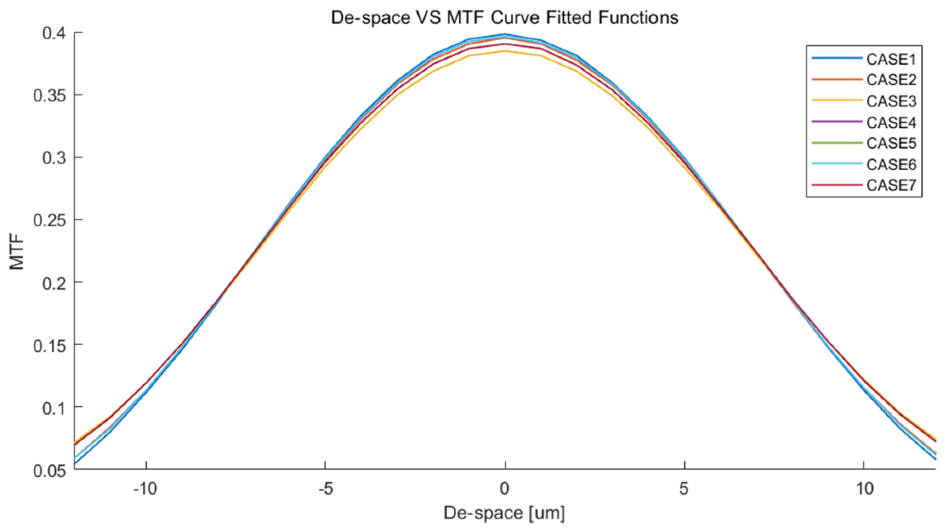
When α and β-Tilts were 200 µrad (Case 3), respectively, the MTF was reduced by 5%, compared to Case 1 (without Tilts), as shown in Figure 2. On the other hand, once the De-space was over ±5 µm, the MTF degraded to below 30%, where the MTF value was a minimum. Furthermore, the degradation of MTF due to De-space is more significant than the degradation caused by Tilt. Therefore, the De-space and α and β-Tilts should be limited by ±5 µm and 200 µrad, respectively. Also, the available range of MTF should be over 30%, which is the minimum value that would allow the optical system to produce a high-resolution image.
Using a DC motor with a rotary encoder, as it will be detailed in the next section, the displacement resolution of the linear screw was identified to 0.1 µm. Since the control resolution for the De-space does not exceed 0.1 µm, a minimum MTF control step of 0.22% is identified.

2.2. Requirements for a Novel Focusing Mechanism

Given that the De-space significantly affects variations in MTF, the design of the focusing mechanism should ensure the restoration of optical alignment mostly by adjusting De-space, with limited adjustments to De-center and Tilt. As shown in Figure 2, by exploiting the relation between the De-space and MTF, the desired range of the De-space was defined to ±10 µm, and the desired De-center and the Tilt were limited to 8.2 µm and 200 µrad, respectively. Accordingly, due to the assigned ranges for the De-space, De-center, and Tilt (See Table 3), the resulting potential range of MTF is greater than 0.35, and a pixel loss can be minimized (less than 1).

2.3. Concept Design and Working Principle of SMFH

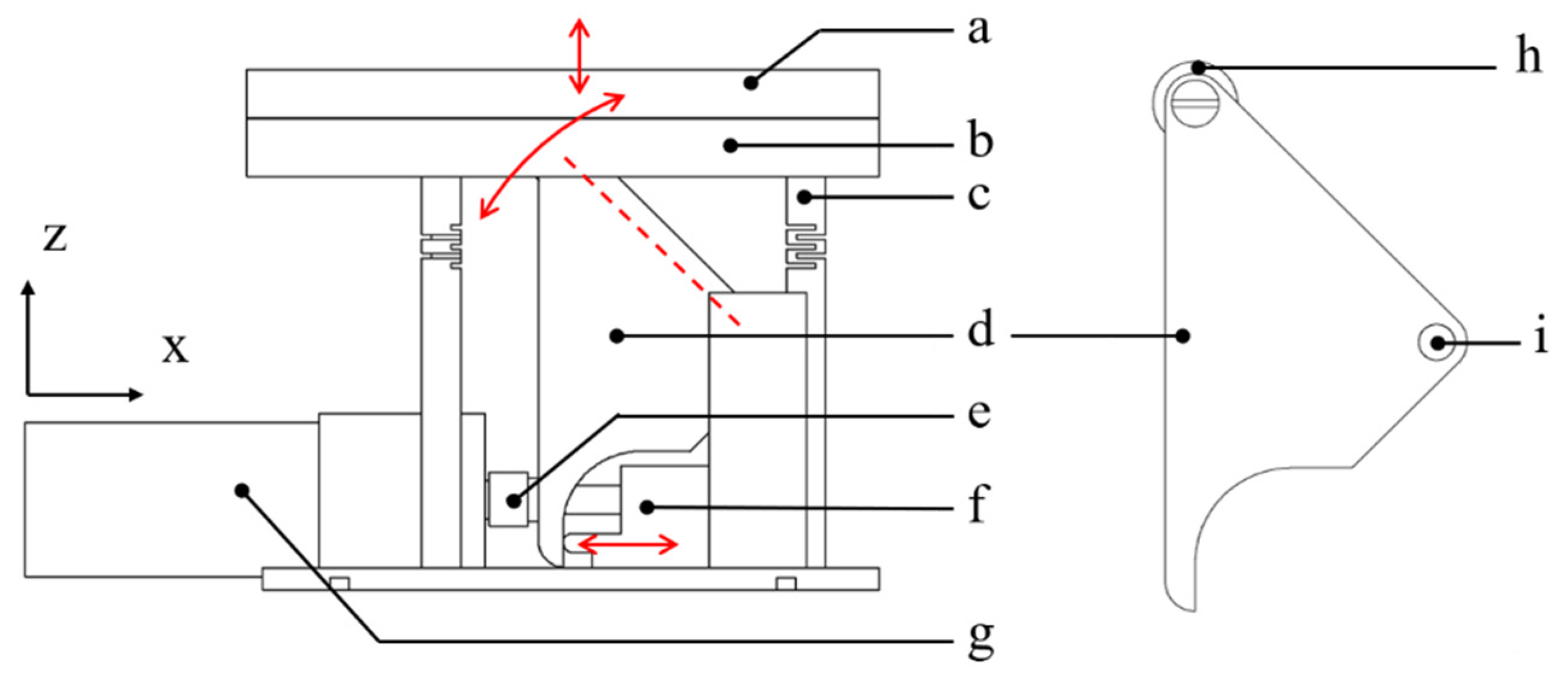
Based on the requirements of the Schmidt–Cassegrain optics system, the focusing mechanism is conceptualized. As shown in Figure 3, the proposed SMFH consists of a. Secondary mirror dummy, b. Secondary mirror supporter, c. Flexure hinge, d. Rotation body, e. Motor screw, f. Linear screw, g. Motor, h. Roller, and i. Rotation shaft. Once the DC motor rotates in CW or CCW, the rotation body induces a deformation, and then each FlexHe is elongated. The detailed working principle is as follows:
  • Once the motor screw that connects the motor shaft rotates CW, it advances the linear screw, enabling the movement of the x-axis (−).
  • The rotation body attached to the end of the linear screw rotates CW.
  • A roller that is mounted at the tip of the rotation body positively displaces the secondary mirror along the z-axis (+), where it contacts the secondary mirror supporter.
  • The three flexure hinges are elongated along the +z-axis, and then it generates the De-spacewith a restoring force.
  • The motor rotates CCW, and then steps 1 to 4 repeat in the opposite direction/order. This process causes the secondary mirror to negatively displace in the z-axis (−).

2.4. Design of Flexure Hinge (FlexHe)

The primary objective of FlexHe is to maximize the displacement in the z-axis (De-space), while at the same minimizing Tilt and De-center in the x and y axes. Accordingly, the structure should be reinforced to resist both bending and torsion, yet be compliant in tension and compression. Moreover, the dimensions should satisfy the requirements that were introduced in the aforementioned section. The presented FlexHe can reduce structural complexity, as well as achieve promising mechanical characteristics. The slits of the FlexHe are geometrically arranged in a zig-zag pattern. The best structure with a relatively high bending stiffness and a more compliant axial stiffness was identified by means of the Finite Element Method.

2.4.1. FEM Modeling of the FlexHe

A finite element (FE) was created in ANSYS 19.2 (ANSYS Inc, Canonsburg, PA, USA) with static structure analysis, and the mechanical characteristics were analyzed (i.e., strain versus stress, strain energy of structure through cyclic loading/un-loading, cyclic fatigue, and fracture). The analysis identified titanium alloys (Ti-6Al-4V) as having suitable material properties for the FlexHe due to its promising material properties for space use (i.e., specific strength, lightweight, low density, etc.) [38].
Each FlexHe type was defined by the number of slits: types 1 to 6 were defined according to slit number [n], which ranged from 2 to 7, respectively. In addition to static characteristics, the fatigue analysis for the FlexHe was carried out under a fully reversed loading condition (tension-compression loading, stress ratio R = −1). Here, the thermal and vibrational effects were neglected. The stress versus the number of cycles to failure (S-N curves) and endurance limits associated with high-cycle fatigue (HCF) were compiled as a reference in [39].
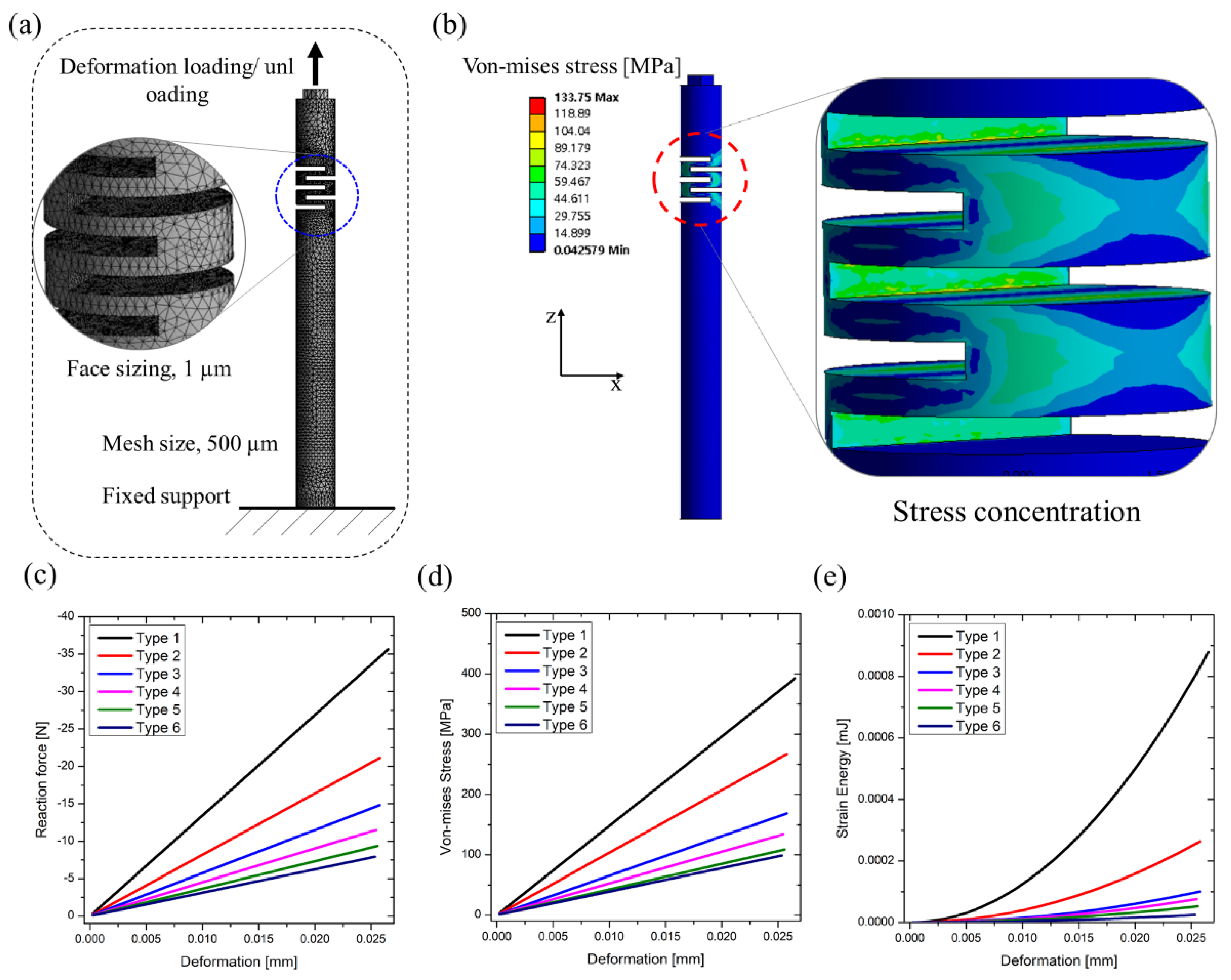
The simulation results showed different mechanical behaviors. First, the greater the number of slits, the less axial stiffness is observed, as depicted in Figure 4c,d. Such compliant characteristics cause the FlexHe to undergo undesired deformations (e.g., buckling or column squirm), since the correlation between the buckling pressure and the stiffness of the structure is proportional [40,41]. Indeed, the axial stiffness of Type 6 is relatively more compliant than Type 1, which indicates that Type 6 could be too delicate for the compression load. Similarly, the plotted relation of the strain energy versus deformation showed that Type 1 has excessive axial stiffness (Reaction force of 35.6 N). Comparing Type 1 with Type 6, the maximum reaction force of Type 6 was only 8 N, which is only 22% of Type 1. In other words, Type 1 needs a relatively strong force in order to achieve the desired deformation, and accordingly, this would consume a lot of energy in small satellite.
In the cases of Types 1 through 3, the relationship between deformation and strain energy showed a non-linear behavior. On the other hand, in cases of Types 4 through 6, we identified that the relationship showed a linear response. Due to this, the strain energy was not dramatically increased even though deformation is imposed. In light of these analyses, we determined that FlexHe Type 4, consisting of five slits, was the optimal structure for the operation. Indeed, as the graphs in Figure 4 demonstrate, Type 4 showed not only relatively high axial stiffness compared to Types 5 and 6, but also relatively compliant rather than Types 1 through 3.
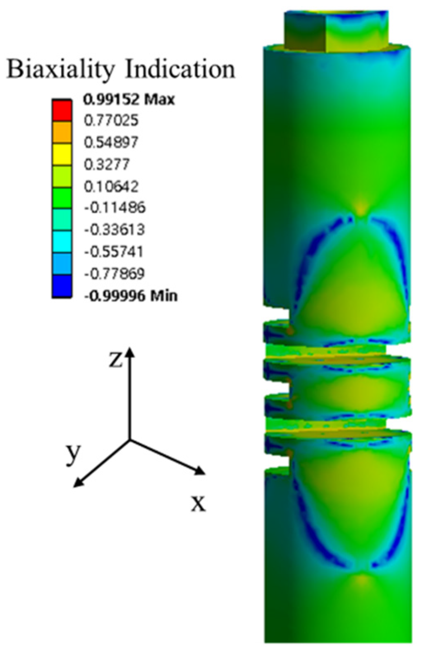
With the optimized FlexHe (Type 4), the constant amplitude load fatigue analysis was carried out. By using the displacement of 25 µm and the estimated reaction force (11.5 N) from the simulation study, various parameters (i.e., alternating equivalent stress, safety factor, biaxial indication, fatigue sensitivity, fatigue life) were evaluated. The local stress was determined by means of the biaxial stress. In general, the biaxiality indication refers to the ratio between the major and minor principal stresses. As a result of fatigue analysis, the biaxial indication ranged between −0.99996 and 0.99152, as shown in Figure 5. Thus, the maximum stress of the FlexHe occurred at the inside of each slit. However, since the minimum safety factor was 6.239 (Not less than 1), the available fatigue life extends the design life to 100,000 cycles at 11.5 N and avoids any critical regions that could cause a material failure and/or fracture. The fatigue sensitivity was computed to identify the variations in the fatigue life according to the loads. As a result, it showed that the fatigue life could be unlimited, even though the maximum load was increased by 150%.

2.4.2. Experimental Investigation for the FlexHe

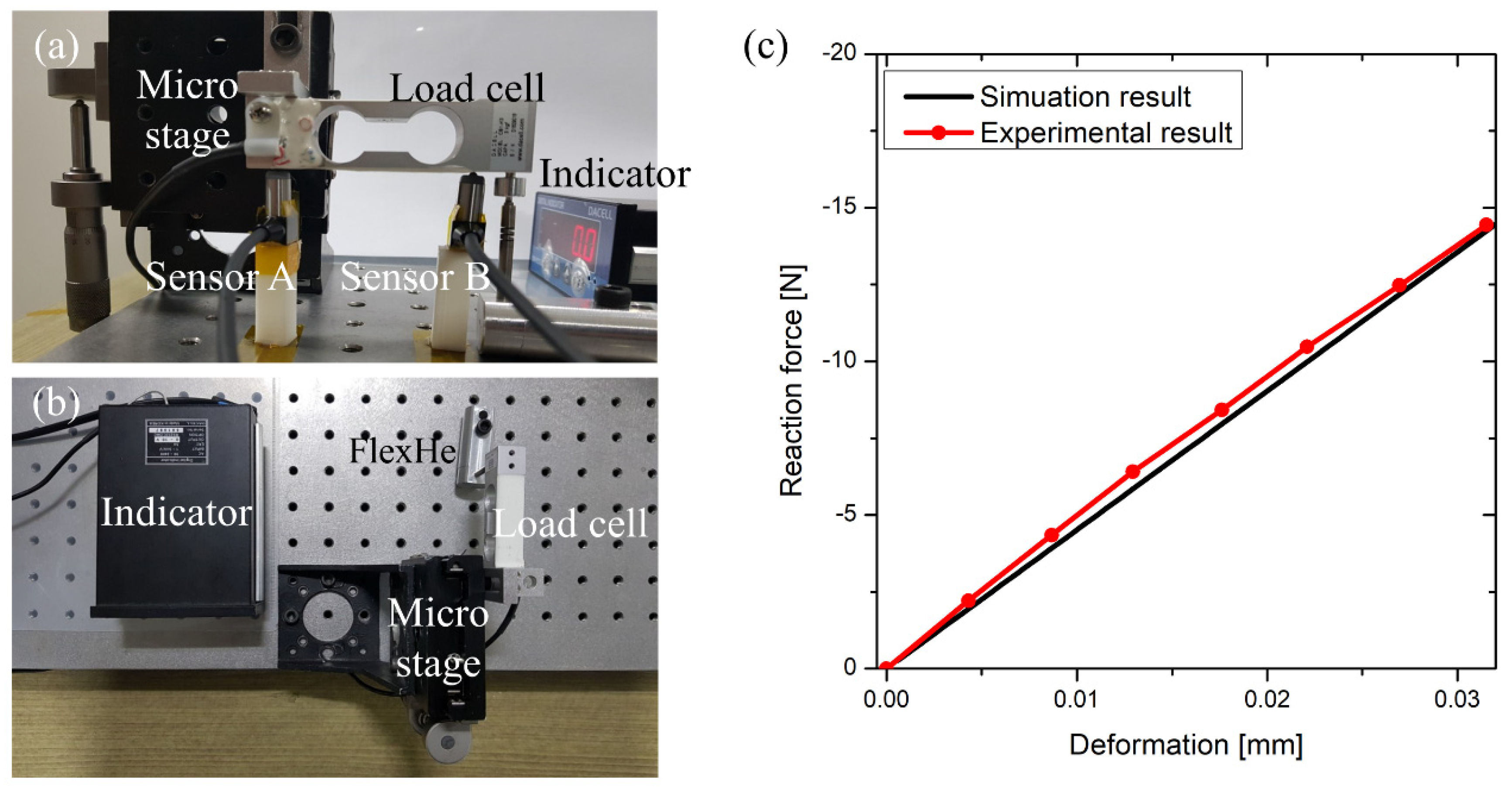
Based on the criteria established through the simulation results, the FlexHe was fabricated and experimentally investigated. As shown in Figure 6a,b, the extension test for a single FlexHe was performed by using a Micro stage with a LVDT sensor, and the reaction force was obtained by using a load cell (Dacell, CB1, South Korea). As per the plotted graph in Figure 6c, the obtained reaction force at a deformation of 23.5 µm was 11.05 N, and the error rate was 4.03% with respect to the simulation result (10.62 N). The relation of the reaction force versus strain showed a linear behavior, and the deformation followed the elastic region of the structure. For a single FlexHe, hysteresis was not observed in both of the experimental and simulation results.
Through the experimental investigation, we identified that the pushing force of the linear screw should be 30 N, so that three FlexHes displace up to 20 µm. With a safety factor of 1.5, a pushing force of 45 N was obtained. Then, according to the loading or unloading phases, the desired torques of the geared motor were theoretically derived, as below:
T L o a d i n g = F d m 2 ( π F d m + l π d m f l )
T U n - l o a d i n g = F d m 2 ( π F d m l π d m + f l )
where F is the required force of the linear screw to push the rotation body, dm is the diameter of the linear screw, f is the friction coefficient, and l is the pitch of the linear screw, respectively. The required torques for the loading and unloading were identified as 28.8 mN·m and 20.6 mN·m, respectively. The geared motor (Maxon Motor®, A-Max 16, customized, Sachseln, Switzerland) with a maximum torque of 230 mN·m was employed by using a safety factor of 8. Also, the employed encoder provides 512 PPR (Pulses/Rev) of resolution; thereby, the system provides the resolution up to 55,296 PPR. Accordingly, considering the pitch of the linear screw (0.5 mm) and the system resolution, the geared motor can be controlled by 0.01 µm, theoretically. However, we observed the undesired error (±5 PPR) during the position control, and thus, the controllable resolution for producing the De-space was determined to 0.1 µm. Therefore, the embedded DC geared motor with the encoder can minimize the error rate of De-space and enables highly precise control of the MTF at increments of 0.22%.

2.5. Fabrication of SMFH and Experimental Setups

Due to the high resolution of displacement control, the proposed SMFH can be controlled at the sub-micrometer level. However, the precision and the repeatability of these adjustments could be diminished due to rough machining tolerances in the fabrication phase. Also, the backlash that occurs between the teeth of different stages within the gearbox and the linear screw could degrade the control precision. Accordingly, we first employed restrictive machining tolerances for each component and polished the surfaces where the sensors contact the secondary mirror supporter, in order to minimize the measurement error. Then, it was integrated with the linear screw and the geared DC motor, as shown in Figure 7.
As shown in Figure 7b, five LVDT sensors were used to coordinate the geometry of the secondary mirror due to the deformation of FlexHes. First, to calculate the orthonormal vector of the plane (De-space and Tilt), three LVDT sensors were arranged at 120° from each other and were attached at the secondary mirror supporter. By using the orthonormal vectors obtained by these sensors, the initial position of the secondary mirror was identified. The other two LVDT sensors were used to obtain the De-center, which was placed at both the x and y-axis of the secondary mirror supporter, respectively. The description of data obtaining spots and vector directions are shown in Figure S1. The employed LVDT sensor provides a high resolution of 0.031 µm with a fast sampling time of 1 ms. Secondly, the DC motor (Maxon Motor®, A-Max 16, customized, Sachseln, Switzerland), having a reduction ratio of 108:1, was integrated. The geared DC motor included a rotary encoder, and each encoder pulse could precisely measure the angle of the motor shaft down to 0.00637°. The motor’s speed was fixed to 50 RPM, and the applied PID values are summarized in Table 4. Then, by converting the encoder data into the displacement of the secondary mirror supporter, input control functions were determined. Here, to reduce the errors due to the backlash, the EPOS2 controller (Maxon Motor®, EPOS2 24/2, Sachseln, Switzerland) that provides a dual loop position control was employed. The control architecture features a proportional controller, and the gain scheduler makes a P gain for the main loop controller to track the errors that could occur between the current and the desired load position. Accordingly, the embedded feedback control enables the system to avoid chattering or hunting due to the backlash. Furthermore, the obtained data from the LVDT sensors, De-space, De-center, and Tilt were compiled by means of MATLAB (MathWorks®, R2018a, Natick, MA, USA).

3. Experimental Results

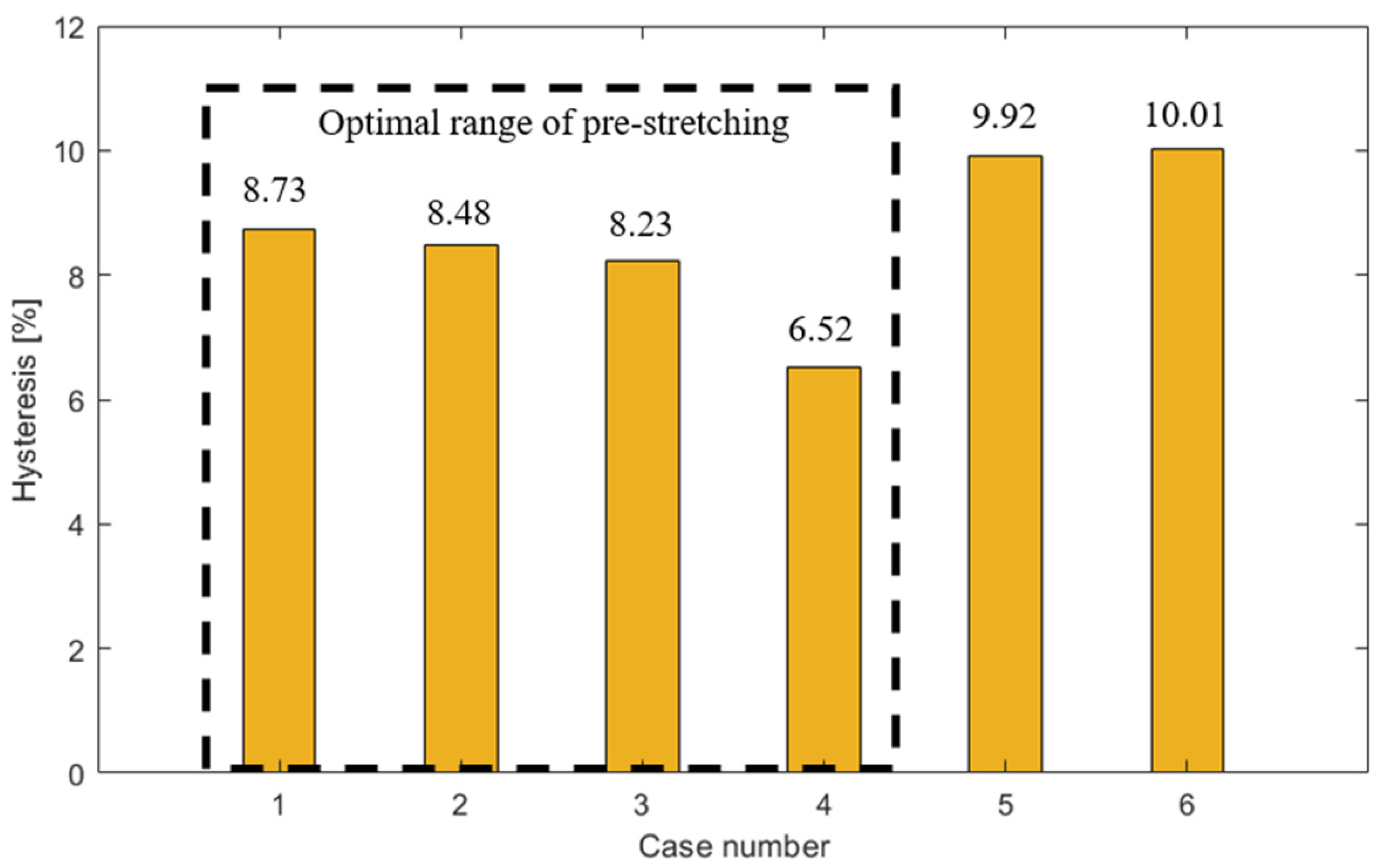
As a result of the rotation body measurements, the relation between the input of the linear screw and the displacements of the rotation body showed a linear behavior. Based on this relationship, the dynamic characteristics of the SMFH were identified by using the SMFH characterization platform. As shown in Figure 8, the hysteresis of the De-space was observed to 8.73%. Such a hysteresis of a flexible structure has been commonly observed, yet it can be reduced by means of a preload in the opposite direction of deformation. Here, the stretched length of 5 µm ensures the unlimited fatigue cycle described in the fatigue analysis section. To investigate the variation of hysteresis, a cyclic loading/unloading was performed. Six comparison groups were made, with steps of 1 µm pre-stretched lengths, ranging from 0 to 5 µm. Here, since the cyclic traveling begins from the offset origin due to its pre-stretched length, the initial point (Pi) of the secondary mirror was defined. Then, starting from the initial point (Pi), a top point (Pt) and a bottom point (Pb) were defined.
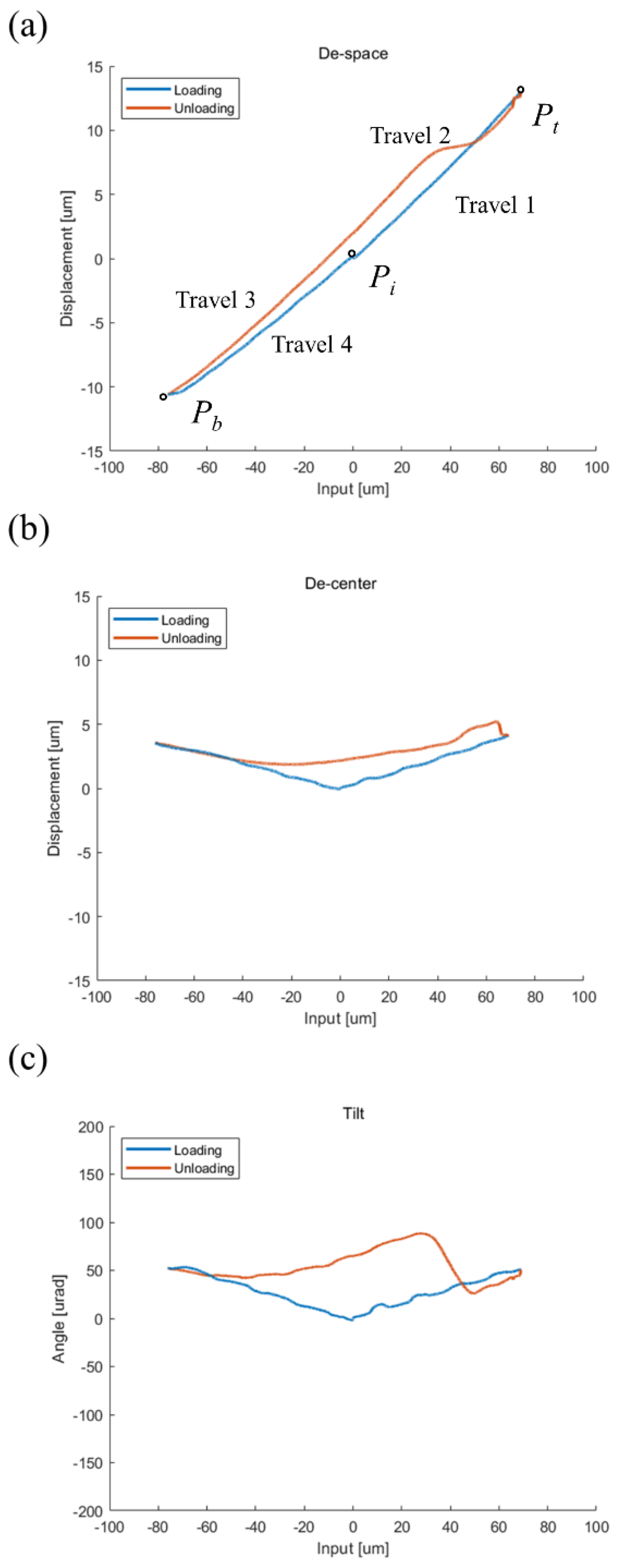
Where Pt and Pb indicate that the De-space is maximized (Positive) and minimized (Negative) from the initial point. Based on these two points, a single cycle was divided into four steps, from Travel 1 to 4, and each phase is as follows: the secondary mirror moves from Pi to Pt (Travel 1), back from Pt to Pi (Travel 2), and moves from Pi to Pb (Travel 3), back again from Pb to Pi (Travel 4). Namely, Travels 1 and 4 represent loading, while Travels 2 and 3 represent unloading.
As shown in Figure 8, Case 4 showed a minimum hysteresis of 6.52% at a pre-stretched length of 3 µm, which represents 25.3% lower hysteresis than Case 1, a non-pre-stretched condition. The maximum error for the loading and unloading cycles was only 1.44 µm. Therefore, the optimal pre-stretched length for the secondary mirror supporter was defined to 3 µm (Case 4). For all cases, the hysteresis and the displacements were summarized in Table 5.
In addition to the investigations of cyclic travel, an evaluation in a zero-gravity environment was performed, as addressed in Supplementary Material (Text S1). Indeed, since the objects on earth are influenced by gravity, SMFH can deflect under their own weight (See Figure S2). These undesired deformations may affect the mechanical behavior of the structure. Accordingly, by compensating for gravity, it is possible to mimic a zero-gravity space environment in the experiment. The derived equation with the defined parameters (See Table S1) eliminates the deflections of SMFH that could occur along the x, y, and z-axes, respectively. To obtain each deflection measurement, the cyclic experiments were performed in 10 trials on each axis.
As shown in Figure 9a, the De-space can range from −10.93 to 13 µm with a hysteresis of 10.46%, and the maximum error for loading and unloading was 2.47 µm. The loading and the unloading cycles were characterized by means of 5th polynomial fitting, in order to avoid the possible errors between the desired and the current De-space due to the hysteresis. As summarized in Table 6, the agreement between the interpolated curve and the experimental curve was very good, with R-square of 99.99%. In the case of De-center, its distribution can range from 0 to 5.2 µm, and the hysteresis was 41.60% (Figure 9b). Conversely, Tilt showed a relatively large hysteresis of 73.63%, yet its response achieved the range of between 0 to 88.45 µrad (Figure 9c).

4. Conclusion and Discussion

In this paper, the SMFH was proposed to correct the mis-alignments of an optical system in small satellites. The presented SMFH corrects the alignment of a secondary mirror in a Schmidt–Cassegrain optical system. A novel structure with radial slits was proposed to reinforce the bending stiffness and maintain compliant axial stiffness. To investigate its mechanical characteristics, a static structural analysis was carried out. As a result, the FlexHe that features five slits was identified as the optimal design. Then, an extension test for a single optimized FlexHe was performed to determine its reaction force. The reaction force applied on the three FlexHes was measured to 30 N. The desired pushing force for the linear screw was measured at approximately 45 N, while multiplying a safety factor of 1.5. Based on the obtained reaction force, a geared motor having a torque of 230 mN·m was employed. The SMFH integrating three FlexHes was fabricated. To identify the proper preload, optimization was performed through an experimental study. By using six different pre-stretched lengths, we obtained a different hysteresis for each case. Among them, Case 4, having a pre-stretched length of 3 µm, showed a minimized hysteresis of 6.52%. For further investigation, the cyclic compression/extension test was repeated in ten trials, and we numerically compensated for any structural deformations caused by gravity. As a result, the proposed SMFH was not only able to generate a 23.93 µm stroke in a longitudinal direction (De-space), but also to achieve a maximum De-center and Tilt of 5.20 µm and 88.45 µrad, respectively. Moreover, given the resolution of the geared motor, the control system allowed the proposed device to achieve a high resolution of De-space control at a maximum of 0.1 µm. The SMFH ensures the requirement of optical alignment. The control resolution for the De-space was not over 0.1 µm; thereby, the minimum control step of MTF identified 0.22%, allowing the maximum MTF to achieve 37%.
Consequently, the proposed SMFH showed promising feasibilities. Among them, the primary contribution of this study is to present a simplified structure that embeds a single motor, and it is anticipated to consume less satellite power. Moreover, in light of our findings on the interpolated relation of the input versus the De-space, a simple yet precise feedback control system can be achieved, without embedding exteroceptive sensors. These promising advantages could provide opportunities that the proposed SMFH will be able to perform the desired objectives passively, and to complete an advanced mechanism ensuring low-cost and simplicity.
However, the need still remains for further studies on the mechanical behaviors of the structure in extreme space environments (i.e., extremely high/low temperature, vacuum, vibration, etc.). With this in mind, our future works will focus on furthering the objectives of simplifying SMFH, reducing satellite size, power consumption, and expense.

5. Patents

Dongkyu, L., Jinwon, J., Seonggun, J., Junwoo, C., Byungkyu, K. (2019). “Korean Patent Registration No. 1020554250000—Focus adjustment device for small satellite and focus adjustment method using the same”.

Supplementary Materials

The following are available online at https://www.mdpi.com/2076-3417/10/20/7087/s1, Text S1: Gravity compensation, Figure S1: (a) Five spots for obtaining displacement data and (b) notation of coordinate and vector directions, Figure S2: Examples of the SMFH orientation with the gravity that acts along (a) -z-direction and (b) -x-direction, Table S1: Parameters for gravity compensation.

Author Contributions

Conceptualization, J.J., D.L. and B.K.; methodology, J.J. and B.K.; software, J.J. and S.J.; validation, J.J. and N.V.S.; formal analysis, J.J.; investigation, J.J. and N.V.S.; data curation, J.J. and N.V.S.; writing—original draft preparation, J.J.; writing—review and editing, S.J., J.H. and B.K.; visualization, J.J. and S.J.; supervision, B.K.; project administration, J.H., and B.K.; funding acquisition, J.H. All authors have read and agreed to the published version of the manuscript.

Funding

This work was supported by Global Surveillance Research Center (GSRC) program funded by the Defense Acquisition Program Administration (DAPA) and Agency for Defense Development (ADD).

Acknowledgments

Dongkyu Lee passed away in December of 2019. He was a dedicated colleague and postdoc in the school of Aerospace and Mechanical Engineering at the Korea Aerospace University, with a passion for researches pertaining to medical robotics and numerical analysis based on Finite Element Methods. He was honored with numerous awards for his research activities and spin-off technologies. Particularly, Dongkyu Lee was recently awarded the Korean presidential prize at University Creative Invention Competition. The authors would like to pay our gratitude and our respects to his efforts for this work. We sincerely hope that his soul rests in peace.

Conflicts of Interest

The authors declare no conflict of interest. And the funders had a role in the decision to publish the results and approved this article to be published.

References

  1. Kramer, H.J.; Cracknell, A.P. An overview of small satellites in remote sensing. Int. J. Remote Sens. 2008, 29, 4285–4337. [Google Scholar] [CrossRef]
  2. Emerging Opportunities for Low-Cost Small Satellites in Civil and Commercial Space. Available online: https://digitalcommons.usu.edu/smallsat/2010/all2010/28/ (accessed on 11 October 2020).
  3. Xue, Y.; Li, Y.; Guang, J.; Zhang, X.; Guo, J. Small satellite remote sensing and applications—History, current and future. Int. J. Remote Sens. 2008, 29, 4339–4372. [Google Scholar] [CrossRef]
  4. Sweeting, M. Modern small satellites-changing the economics of space. Proc. IEEE 2018, 106, 343–361. [Google Scholar] [CrossRef]
  5. Clements, R.; Tavares, P.; Lima, P. Small satellite attitude control based on a Kalman filter. In Proceedings of the 2000 IEEE International Symposium on Intelligent Control. Held jointly with the 8th IEEE Mediterranean Conference on Control and Automation (Cat. No. 00CH37147), Rio Patras, Greece, 19 July 2000; pp. 79–84. [Google Scholar]
  6. Radhakrishnan, R.; Edmonson, W.W.; Afghah, F.; Rodriguez-Osorio, R.M.; Pinto, F.; Burleigh, S.C. Survey of inter-satellite communication for small satellite systems: Physical layer to network layer view. IEEE Commun. Surv. Tutor. 2016, 18, 2442–2473. [Google Scholar] [CrossRef] [Green Version]
  7. Lascombes, P. Electric propulsion for small satellites orbit control and deorbiting: The example of a Hall Effect thruster. In Proceedings of the 2018 SpaceOps Conference, Marseille, France, 28 May–1 June 2018; p. 2729. [Google Scholar]
  8. Neel, N.C., III; Cotten, D.L.; Mishra, D.R. The Spectral Ocean Color (SPOC) Small Satellite Mission: Developing an Adjustable Multispectral Imager. AGUFM 2018, 2018, ED43G-1295. [Google Scholar]
  9. Gopalswamy, N.; Gong, Q. A small satellite mission for solar coronagraphy. In Proceedings of the CubeSats and NanoSats for Remote Sensing II, San Diego, CA, USA, 19–23 August 2018; p. 107690X. [Google Scholar]
  10. Fajardo, I.; Lidtke, A.A.; Bendoukha, S.A.; Gonzalez-Llorente, J.; Rodríguez, R.; Morales, R.; Faizullin, D.; Matsuoka, M.; Urakami, N.; Kawauchi, R. Design, Implementation, and Operation of a Small Satellite Mission to Explore the Space Weather Effects in Leo. Aerospace 2019, 6, 108. [Google Scholar] [CrossRef] [Green Version]
  11. Shakir, A.B.; Ez-Deen, S.Y. Effect of acoustic vibration on the satellite structure at launch stage. In Proceedings of the International Conference on Modeling and Simulation (MS09) Trivandrum, Kerala, India, 1–3 December 2009; p. 3. [Google Scholar]
  12. Lee, D.-O.; Han, J.-H.; Jang, H.-W.; Woo, S.-H.; Kim, K.-W. Shock response prediction of a low altitude earth observation satellite during launch vehicle separation. Int. J. Aeronaut. Space Sci. 2010, 11, 49–57. [Google Scholar] [CrossRef]
  13. Johnson, C.; Wilke, P. Protecting satellites from the dynamics of the launch environment. In Proceedings of the AIAA Space 2003 Conference & Exposition, Long Beach, CA, USA, 23–25 September 2003; p. 6266. [Google Scholar]
  14. Neudeck, P.G.; Prokop, N.F.; Greer III, L.C.; Chen, L.Y.; Krasowski, M.J. Low earth orbit space environment testing of extreme temperature 6H-SiC JFETs on the international space station. Mater. Sci. Forum 2011, 679–680, 579–582. [Google Scholar] [CrossRef] [Green Version]
  15. Jiao, Z.; Jiang, L.; Sun, J.; Huang, J.; Zhu, Y. Outgassing environment of spacecraft: An overview. In Proceedings of the IOP Conference Series: Materials Science and Engineering, Wuhan, China, 19–21 July 2019; p. 012071. [Google Scholar]
  16. Shimamura, H.; Yamagata, I. Degradation of mechanical properties of polyimide film exposed to space environment. J. Spacecr. Rockets 2009, 46, 15–21. [Google Scholar] [CrossRef]
  17. Darrin, M.A.G.; Buchner, S.P.; Martin, M. The Impact of the Space Radiation Environment on Micro Electro Mechanical Systems (MEMS) and Microstructures. In Proceedings of the 2005 8th European Conference on Radiation and Its Effects on Components and Systems, Cap d’Agde, France, 19–23 September 2005; pp. H1-1–H1-5. [Google Scholar]
  18. Outgassing Data for Selecting Spacecraft Materials. Available online: https://ntrs.nasa.gov/citations/20030053424 (accessed on 11 October 2020).
  19. Schläppi, B.; Altwegg, K.; Balsiger, H.; Hässig, M.; Jäckel, A.; Wurz, P.; Fiethe, B.; Rubin, M.; Fuselier, S.; Berthelier, J.-J. Influence of spacecraft outgassing on the exploration of tenuous atmospheres with in situ mass spectrometry. J. Geophys. Res. Space Phys. 2010, 115, A12312. [Google Scholar] [CrossRef]
  20. Kim, H.-I.; Yoon, J.-S.; Kim, H.-B.; Han, J.-H. Measurement of the thermal expansion of space structures using fiber Bragg grating sensors and displacement measuring interferometers. Meas. Sci. Technol. 2010, 21, 085704. [Google Scholar] [CrossRef]
  21. Lee, S.; Shin, D. On-orbit camera mis-alignment estimation framework and its application to earth observation satellite. Remote Sens. 2015, 7, 3320–3346. [Google Scholar] [CrossRef] [Green Version]
  22. Murthy, K.; Shearn, M.; Smiley, B.D.; Chau, A.H.; Levine, J.; Robinson, M.D. SkySat-1: Very high-resolution imagery from a small satellite. In Proceedings of the Sensors, Systems, and Next-Generation Satellites XVIII, Amsterdam, The Netherlands, 22–25 September 2014; p. 92411E. [Google Scholar]
  23. Hwang, H.; Choi, Y.-W.; Kwak, S.; Kim, M.; Park, W. MTF assessment of high resolution satellite images using ISO 12233 slanted-edge method. In Proceedings of the Image and Signal Processing for Remote Sensing XIV, Cardiff, UK, 15–18 September 2008; p. 710905. [Google Scholar]
  24. Gooding, D.; Richardson, G.; Haslehurst, A.; Smith, D.; Saunders, C.; Aglietti, G.; Blows, R.; Shore, J.; Hampson, K.; Booth, M. A novel deployable telescope to facilitate a low-cost <1m GSD video rapid-revisit small satellite constellation. In Proceedings of the International Conference on Space Optics—ICSO 2018, Chania, Greece, 9–12 October 2018; p. 1118009. [Google Scholar]
  25. Faran, S.; Eshet, I.; Yehezkel, N.; Molcho, J. Estimation of the MTF of a satellite imaging-system from celestial scenes. In Proceedings of the 2009 IEEE International Geoscience and Remote Sensing Symposium, Cape Town, South Africa, 12–17 July 2009; pp. II-452–II-455. [Google Scholar]
  26. Li, X.; Jiang, X.; Zhou, C.; Gao, C.; Xi, X. An analysis of the knife-edge method for on-orbit MTF estimation of optical sensors. Int. J. Remote Sens. 2010, 31, 4995–5010. [Google Scholar] [CrossRef]
  27. Cardei, V.; Fowler, B.; Kavusi, S.; Phillips, J. MTF Measurements of Wide Field of View Cameras. Electron. Imaging 2016, 2016, 1–5. [Google Scholar] [CrossRef]
  28. Choi, Y.-W.; Yang, S.-U.; Kang, M.-S.; Kim, E.-E. Development of high-performance optical system for small satellites. In Proceedings of the Earth Observing Systems XII, San Diego, CA, USA, 16–30 August 2007; p. 66771A. [Google Scholar]
  29. Cho, D.-H.; Choi, W.-S.; Kim, M.-K.; Kim, J.-H.; Sim, E.; Kim, H.-D. High-Resolution Image and Video CubeSat (HiREV): Development of Space Technology Test Platform Using a Low-Cost CubeSat Platform. Int. J. Aerosp. Eng. 2019, 2019, 8916416. [Google Scholar] [CrossRef]
  30. Asadnezhad, M.; Eslamimajd, A.; Hajghassem, H. Optical system design of star sensor and stray light analysis. J. Eur. Opt. Soc.-Rapid Publ. 2018, 14, 9. [Google Scholar] [CrossRef] [Green Version]
  31. Lee, S.-Y.; Kim, G.; Lee, Y.-S.; Kim, G.-H. Optical design and tolerance analysis of a new off-axis infrared collimator. Int. J. Precis. Eng. Manuf. 2014, 15, 1883–1888. [Google Scholar] [CrossRef]
  32. Franzoso, A.; D’Imporzano, R. A sub-micrometric thermal refocussing mechanism for High Resolution EO telescopes. In Proceedings of the 45th International Conference on Environmental Systems, Bellevue, WA, USA, 12–16 July 2015. [Google Scholar]
  33. Selımoglu, O.; Ekinci, M.; Karcı, O. Thermal refocusing method for spaceborne high-resolution optical imagers. Appl. Opt. 2016, 55, 4109–4112. [Google Scholar] [CrossRef]
  34. Raval, A. A detail review of optical misalignment and corrected by refocusing mechanism. Int. J. Sci. Res. Dev. 2015, 3, 778–783. [Google Scholar]
  35. Kuo, J.-C.; Ling, J. Optical telescope refocussing mechanism concept design on remote sensing satellite. In Proceedings of the International Conference on Space Optics—ICSO 2016, Biarritz, France, 18–21 October 2016; p. 105624F. [Google Scholar]
  36. Jo, J.-B.; Hwang, J.-H.; Bae, J.-S. Online refocusing algorithm for a satellite camera using stellar sources. Opt. Express 2016, 24, 5411–5422. [Google Scholar] [CrossRef]
  37. Lee, D.-H.; Hwang, J.-h. An Online Tilt Estimation and Compensation Algorithm for a Small Satellite Camera. Int. J. Aeronaut. Space Sci. 2018, 19, 172–182. [Google Scholar] [CrossRef]
  38. Kostov, A.; Friedrich, B. Predicting thermodynamic stability of crucible oxides in molten titanium and titanium alloys. Comput. Mater. Sci. 2006, 38, 374–385. [Google Scholar] [CrossRef]
  39. Carrion, P.E.; Shamsaei, N. Strain-based fatigue data for Ti–6Al–4V ELI under fully-reversed and mean strain loads. Data Brief 2016, 7, 12–15. [Google Scholar] [CrossRef] [Green Version]
  40. Newland, D. Buckling of double bellows expansion joints under internal pressure. J. Mech. Eng. Sci. 1964, 6, 270–277. [Google Scholar] [CrossRef]
  41. Kucukler, M.; Gardner, L.; Macorini, L. Flexural–torsional buckling assessment of steel beam–columns through a stiffness reduction method. Eng. Struct. 2015, 101, 662–676. [Google Scholar] [CrossRef] [Green Version]
Figure 1. Undesired mis-alignments that occur at the secondary mirror; (a) De-space, (b) De-center, (c) Tilt, and (d) definition of α-Tilt and β-Tilt.
Applsci 10 07087 g001
Figure 2. Relation of MTF to De-space, with respect to the Tilt.
Applsci 10 07087 g002
Figure 3. Concept design of the SMFH, consisting of a. Secondary mirror dummy, b. Secondary mirror supporter, c. Flexure hinge, d. Rotation body, e. Motor screw, f. Linear screw, g. Motor, h. Roller, i. Rotation shaft.
Applsci 10 07087 g003
Figure 4. Static simulation results of the flexure hinge; (a) Simulation setup, (b) Distribution of the Von-mises stress along with the flexure hinge and stress concentration on each slit; the plotted graphs of (c) Reaction force at the fixed support versus deformation, (d) Von-mises stress versus deformation, and (e) Strain energy versus deformation.
Applsci 10 07087 g004
Figure 5. Fatigue analysis result, showing a biaxiality indication.
Applsci 10 07087 g005
Figure 6. Experimental investigations on the axial stiffness; an experimental setup in (a) side view, and (b) top view, and (c) a plotted graph of deformation versus the reaction force (Black line: simulation result, Red dotted line: experiment result).
Applsci 10 07087 g006
Figure 7. Photographs of the experimental setups; (a) Characterization of the rotation body, (b) Characterization of SMFH with five LVDT sensors for measuring a. vertical, b. horizontal displacements, and c. one-geared DC motor.
Applsci 10 07087 g007
Figure 8. Optimal pre-stretching experiment results.
Applsci 10 07087 g008
Figure 9. Experimental results for the input versus the optical alignments; (a) De-space, (b) De-center, and (c) Tilt.
Applsci 10 07087 g009
Table 1. Conceptual optical system specifications.
ItemDescription
Optics TypeSchmidt-Cassegrain
Schmidt plate diameter200 mm
Primary mirror diameter200 mm
Primary mirror curvature (radius)551.71 mm
Secondary mirror diameter65 mm
Secondary mirror curvature (radius)185.92 mm
Altitude685 km
GSD2.8 m
Detector35.8 × 23.8 mm CMOS sensor
Pixel size8.2 µm
Swath Width12 km
MTF≥30%, @Optical Design, Nyquist Freq.
Linear Obscuration≤0.35
F/#10
Table 2. Case study to identify the variation of MTF.
α-Tilt (µrad)β-Tilt (µrad)MTF at De-Space = 0
CASE 1000.398
CASE 21001000.395
CASE 32002000.385
CASE 410000.396
CASE 520000.391
CASE 601000.396
CASE 702000.391
Table 3. The requirements of the optical alignments; De-space, De-center, and Tilt.
Optical AlignmentRequirement
De-space stroke range±10 µm
Maximum De-center8.2 µm
Maximum Tilt200 µrad
Table 4. The employed control parameters to implement the feedback system.
Control ParameterPID
Value4718861
Table 5. Analysis of hysteresis according to the pre-stretched lengths.
Case123456
Pre-stretched length [µm]012345
Top point [µm]202122232425
Initial point [µm]101112131415
Bottom point [µm]012345
Maximum hysteresis [µm]1.941.911.841.442.262.11
Full-scale output range [µm]22.2222.5622.3822.1522.7523.66
Hysteresis [%]8.738.488.236.529.9210.01
Table 6. 5th Polynomial function and parameters.
Polynomial Curve Fitting Function: A0 + A1·x + A2·x2 + A3·x3 + A4·x4 + A5·x5
ParameterA0A1A2A3A4A5
Loading1.41 × 10−11.60 × 10−12.34 × 10−44.59 × 10−66.40 × 10−9−6.66 × 10⁻¹⁰
Unloading2.261.99 × 10−1−5.65 × 10⁻⁵−2.09 × 10−58.08 × 10−82.71 × 10⁻⁹