Study on Mechanical Properties and Cracking Mode of Coal Samples under Compression–Shear Coupled Load Considering the Effect of Loading Rate
Abstract
1. Introduction
2. Materials and Methods
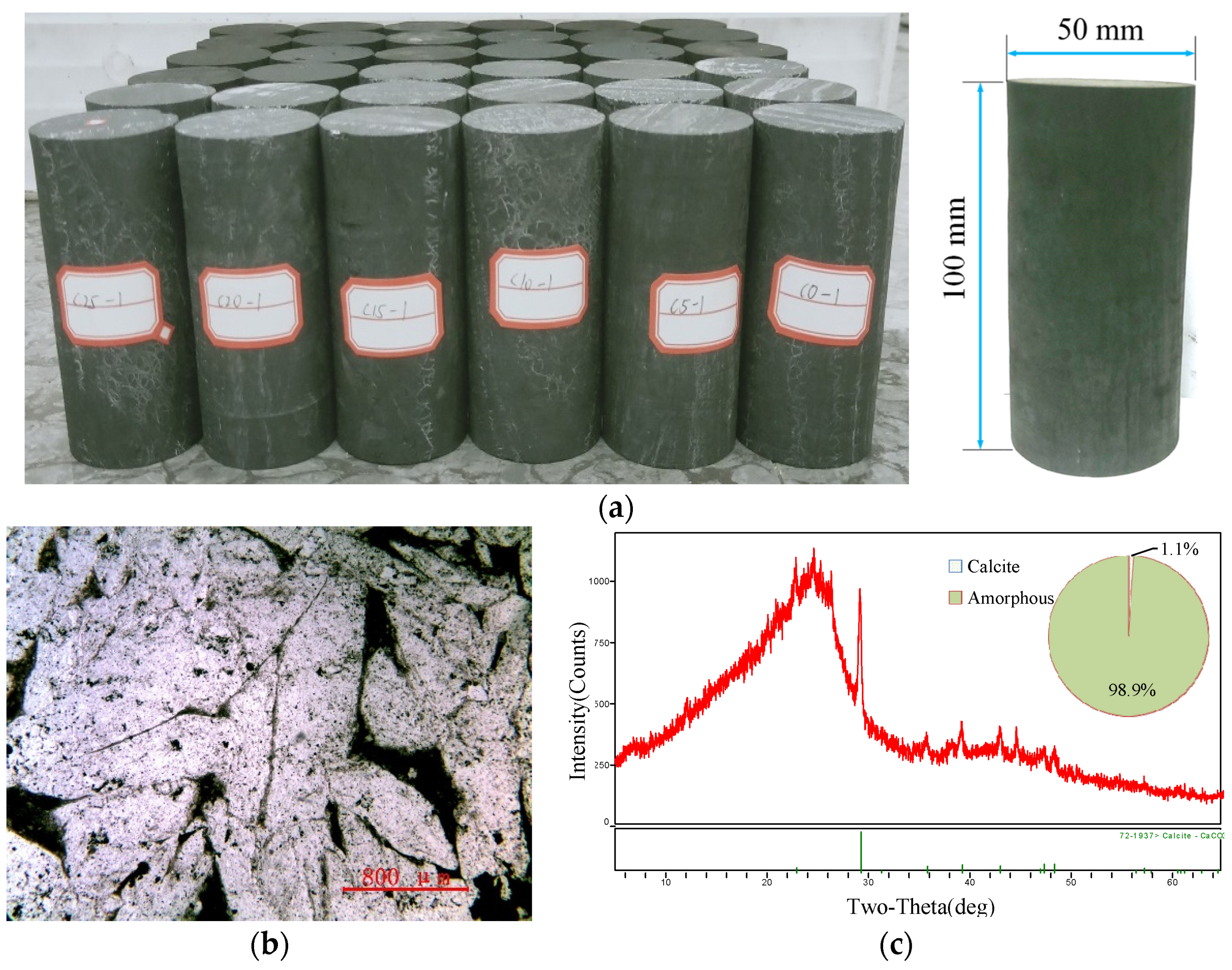
2.1. Materials
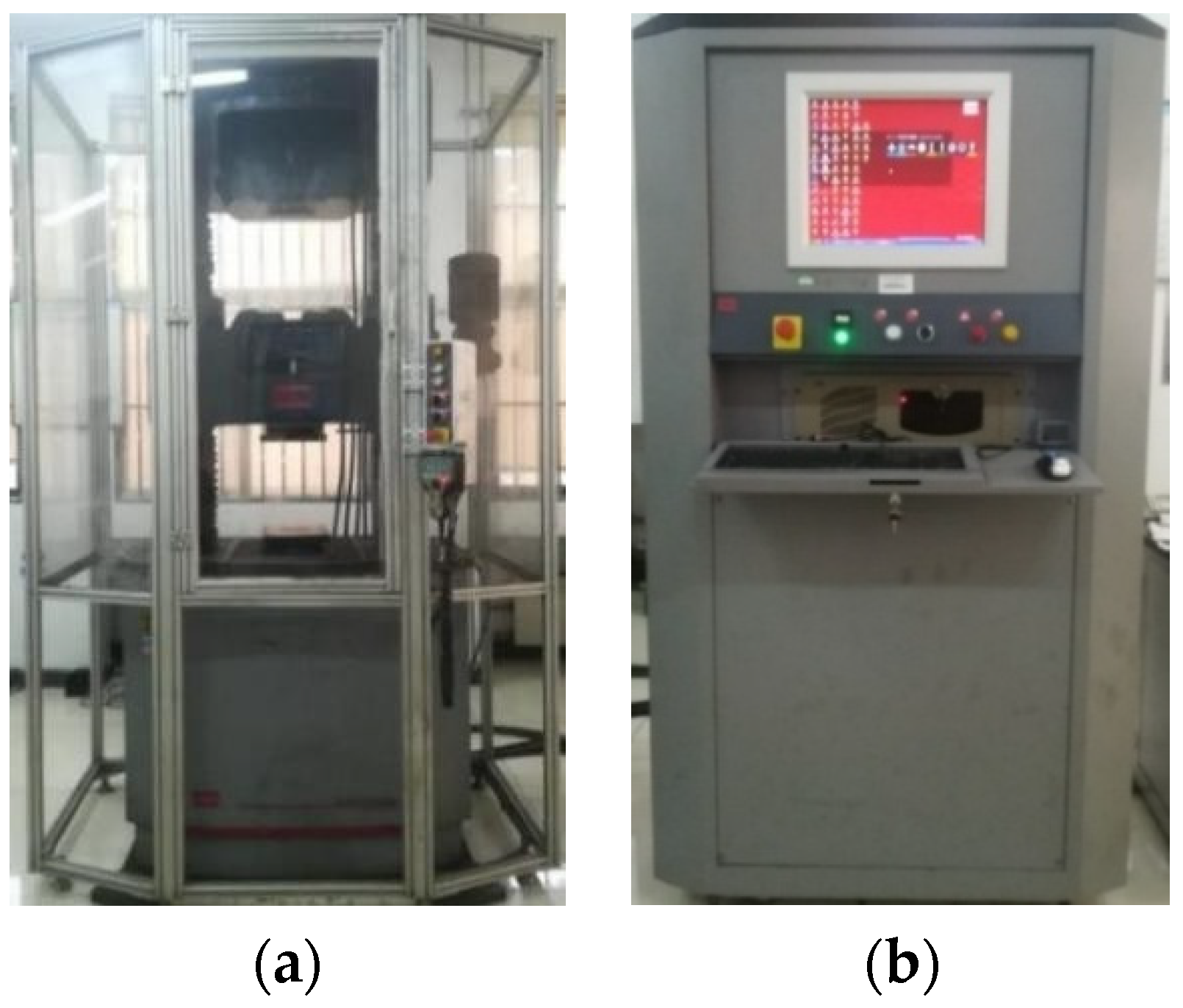
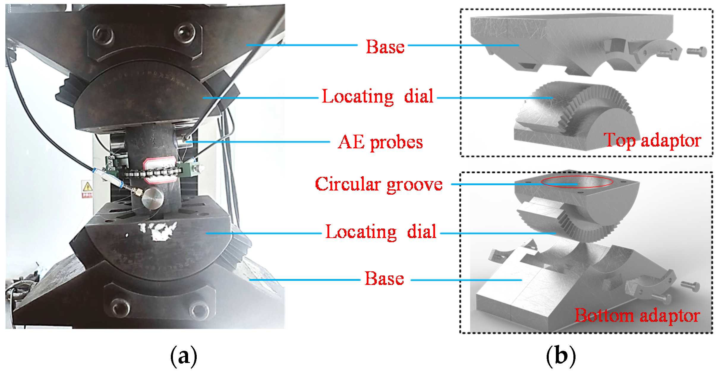
2.2. Experimental Equipment and Strength Calculation Method
2.3. Experimental Scheme
2.4. Acoustic Emission Characterization of Cracking Mode
3. Experimental Results Analysis
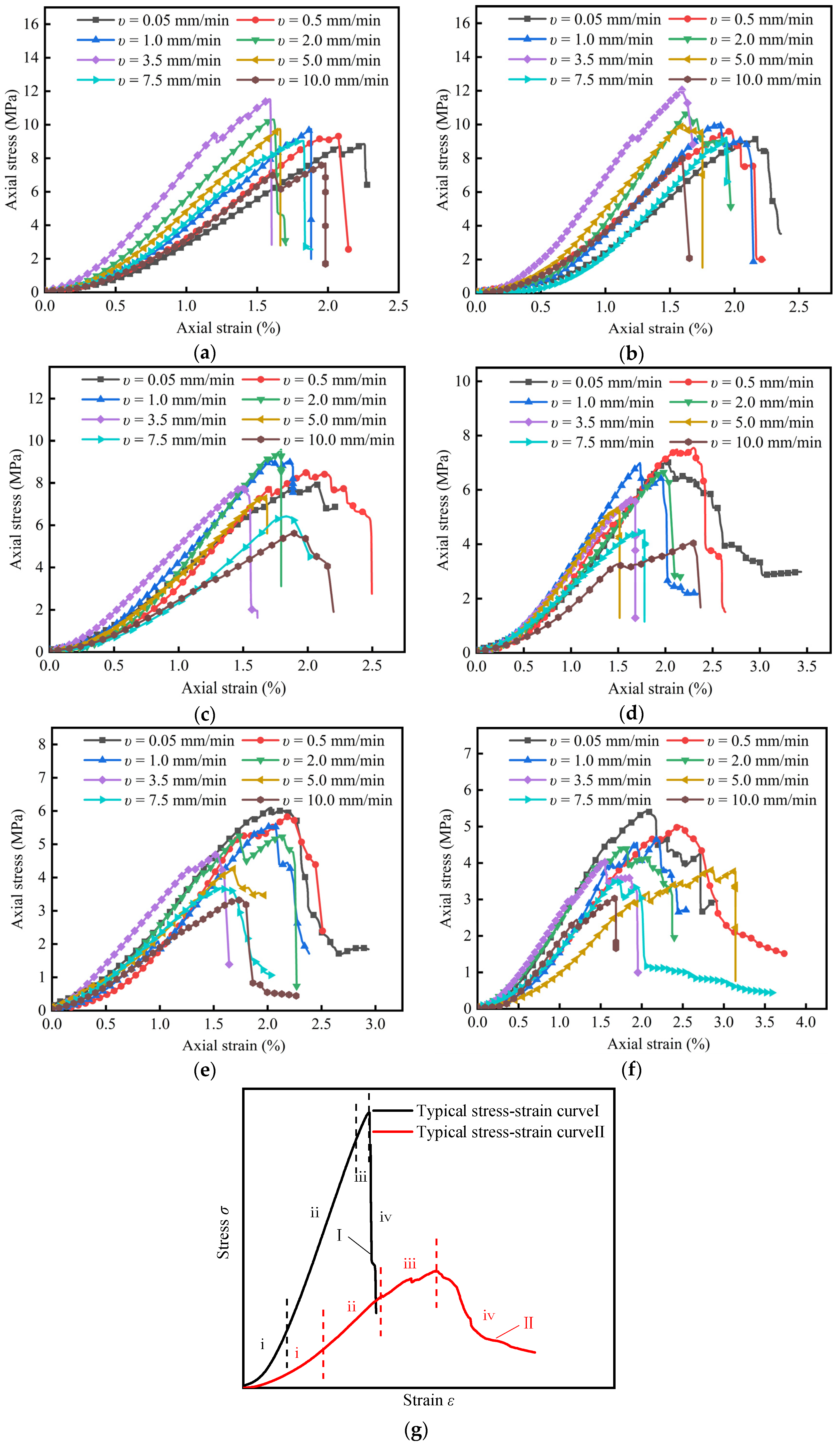
3.1. Effect of Loading Rate and Inclination Angle on the Axial Stress–Strain Curve
3.2. Effect of Loading Rate and Inclination Angle on Shear Stress Componen–Shear Displacement Curve
3.3. Effect of Loading Rate and Inclination Angle on Peak Shear Stress
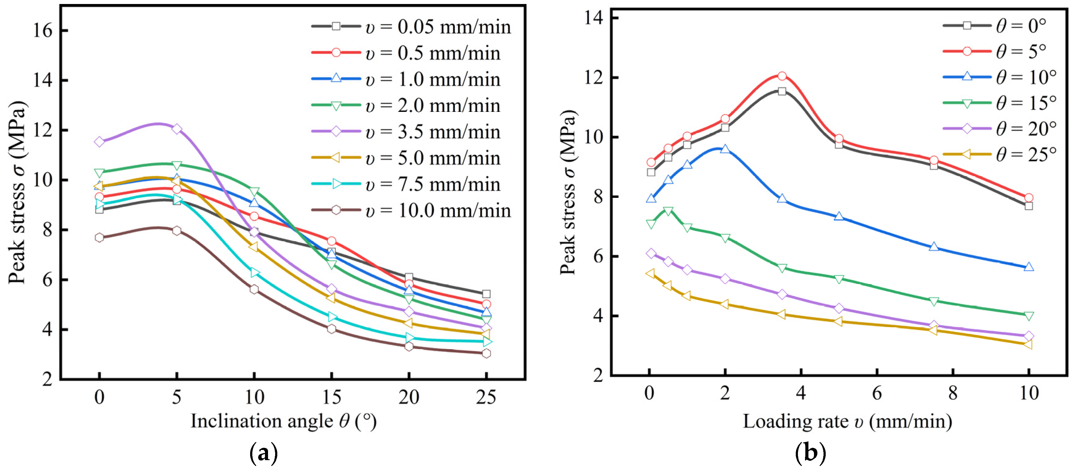
3.4. Effect of Loading Rate and Inclination Angles on Peak Axial Stress
3.5. Effect of Loading Rate and Inclination Angle on the Elastic Modulus
3.6. Effect of Loading Rate and Inclination Angle on Macroscopic Failure Characteristics of Coal Samples
4. Evolution Law of Crack Cracking Mode under the Coupled Compression–Shear Loading
Influence of Inclination Angle on the Evolution of Tension and Shear Cracks in Coal Samples
5. Discussion
6. Conclusions
- The combined compression and shear loading experimental system is developed, the specific assembly steps and use methods of the system are described, and the strength calculation principle of coal samples under the coupled compression–shear loading is introduced. Compared with the traditional uniaxial compression experimental system, the system can realize uniaxial loading of coal samples under the inclined condition. As a result, the sample is in the coupled compression–shear loading mechanical state, and the mechanical status of inclined pillars affected by coupled compression–shear loading can be effectively reflected.
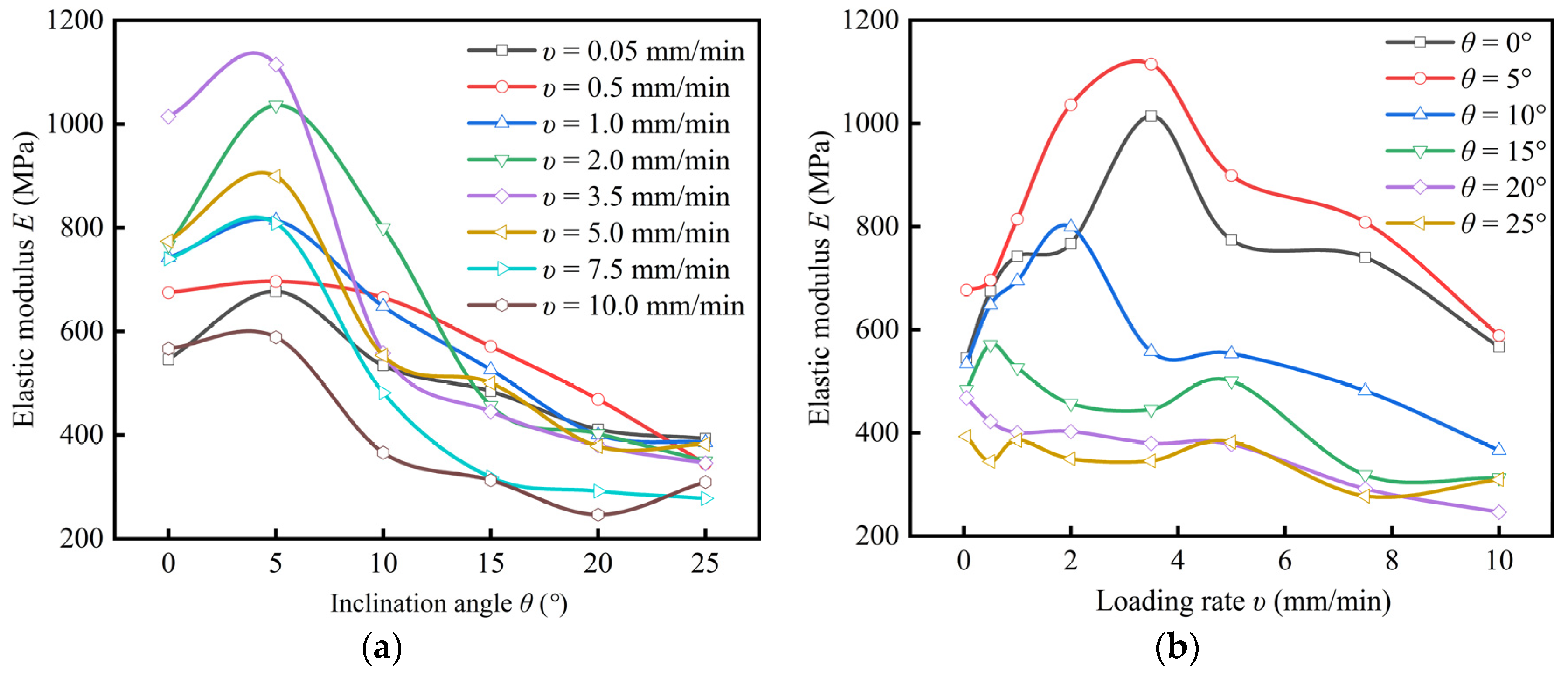
- With the increase of inclination angle, the peak shear stress of coal samples increases gradually, while the peak axial stress and elastic modulus slightly increase and then decrease, and reach the maximum value at the inclination angle of 5°. Within the inclination angle range of 0° to 15°, with the increase of loading rate, the peak shear stress, peak axial stress and elastic modulus of coal sample first increase and then decrease; the loading rate corresponding to the maximum point decreases with the increase of inclination angle. Within the range of 20° to 25°, the peak axial stress and elastic modulus gradually decrease with the increase of the loading rate. It indicates that the shear stress component can weaken the strengthening effect of the loading rate on the strength of coal samples.
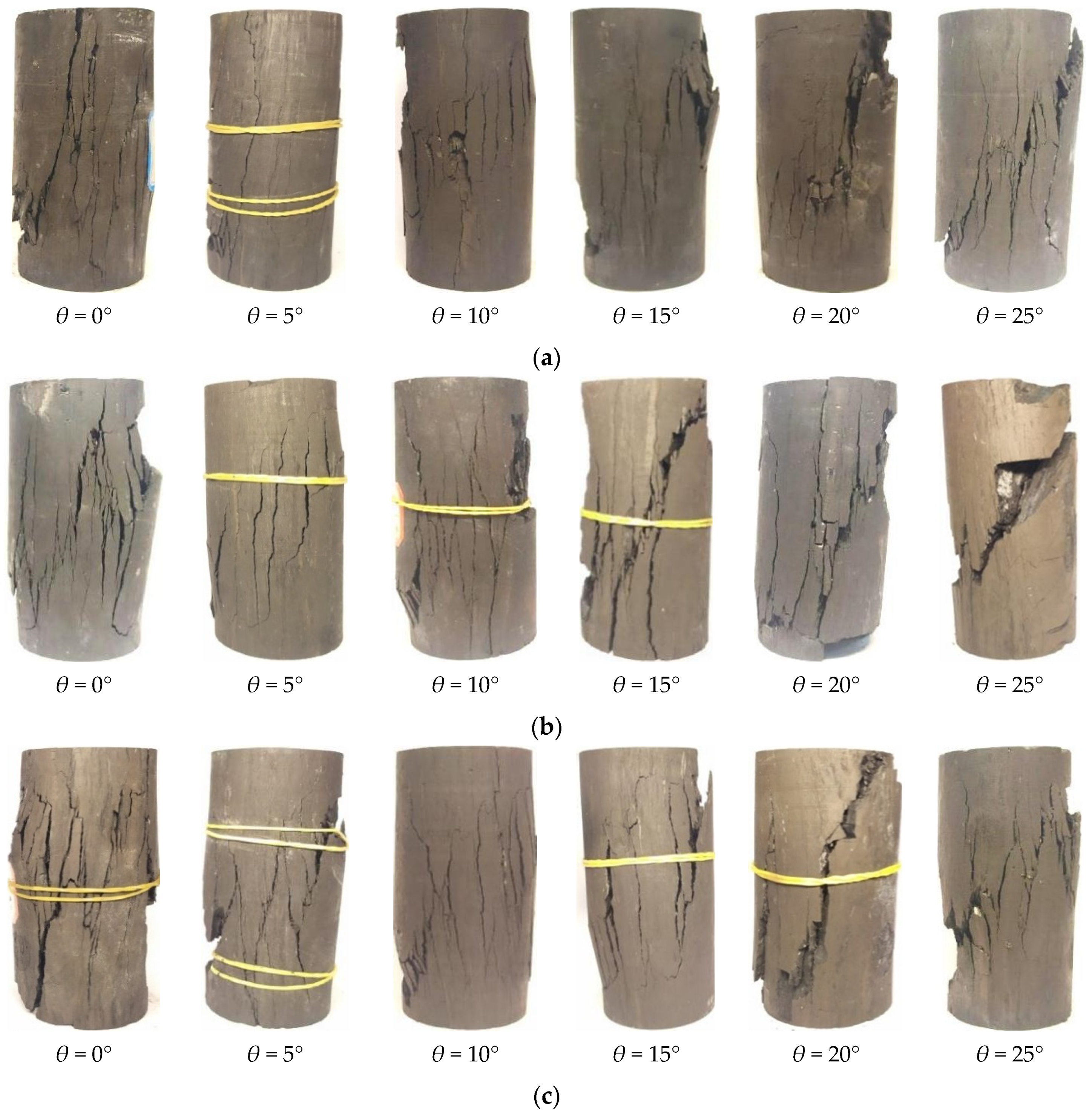
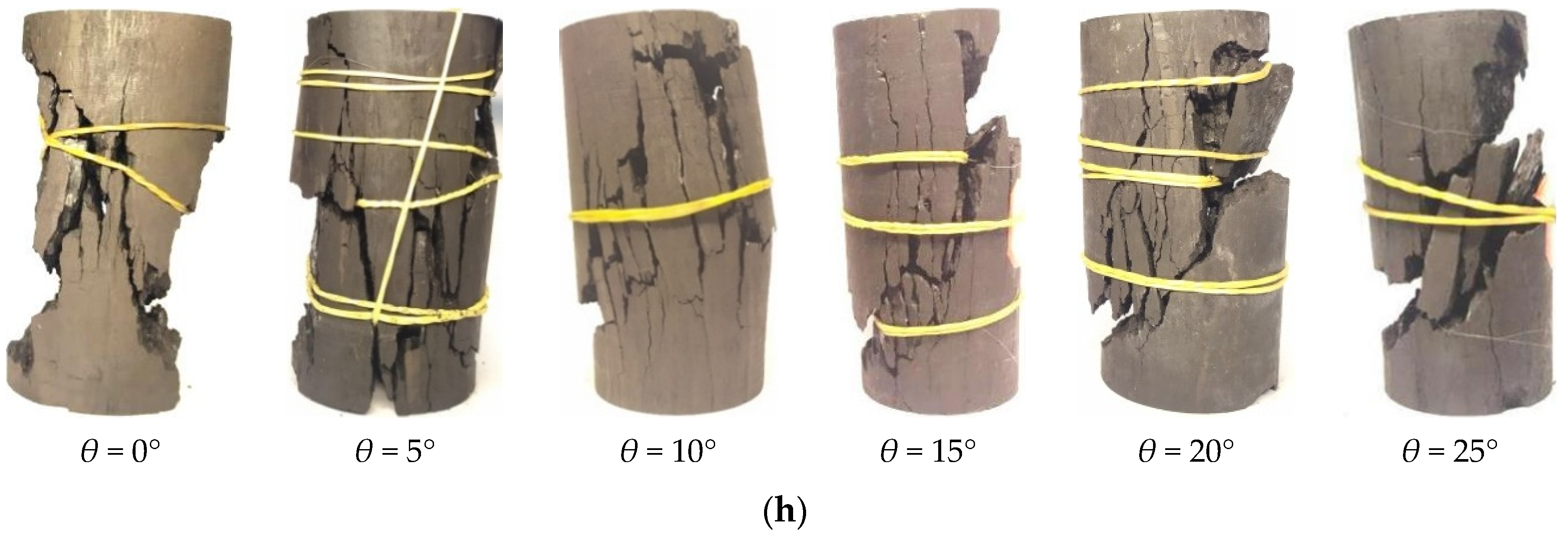
- The influence of inclination angle and loading rate on the failure characteristics of coal samples is significant. With the increase of the inclination angle, the failure mode is transformed from tensile splitting failure (0°–5°), tension–shear composite failure (10°) to single shear failure mode (15°–25°); the loading rate has little effect on the failure mode, but has a significant effect on the failure degree.
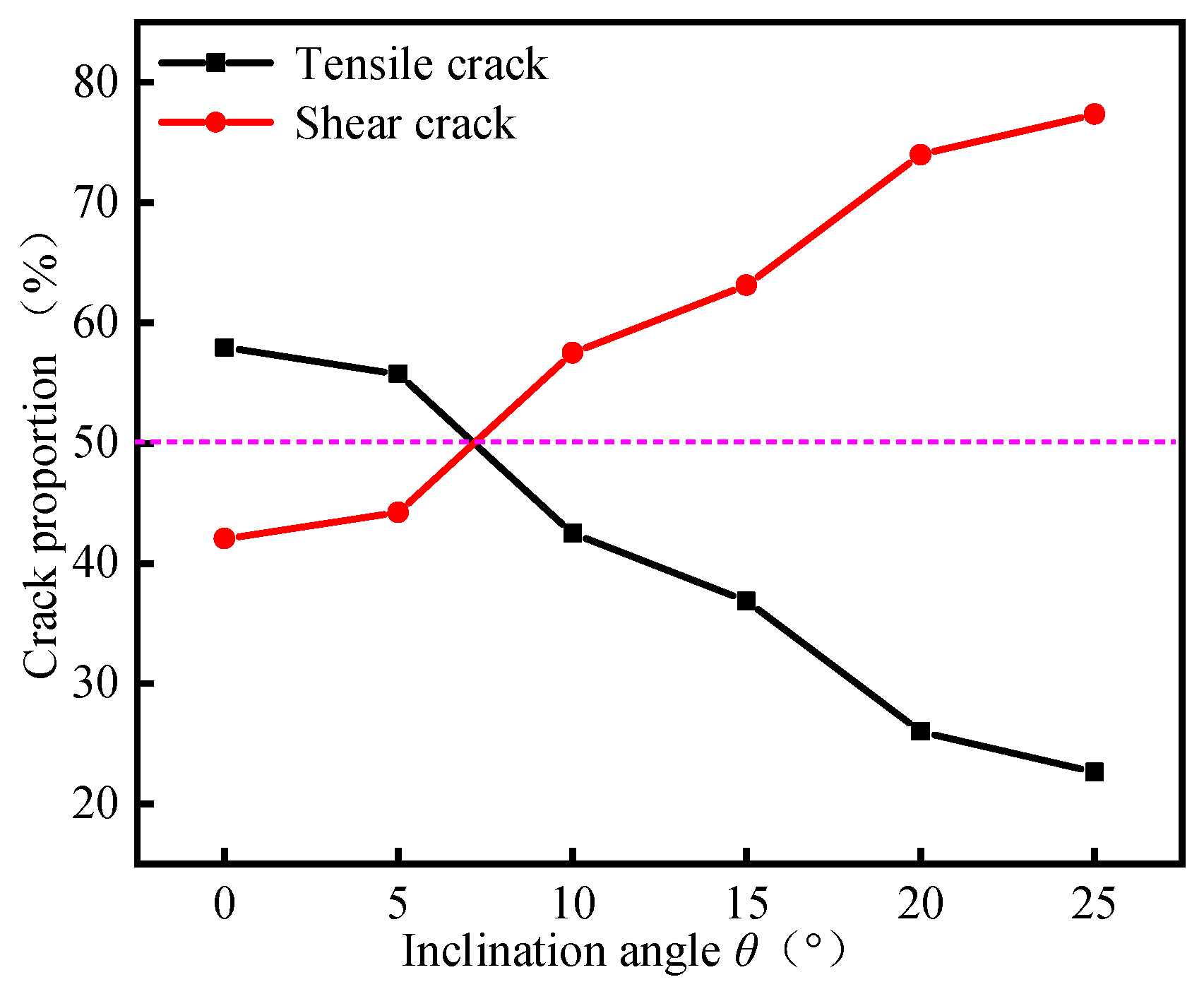
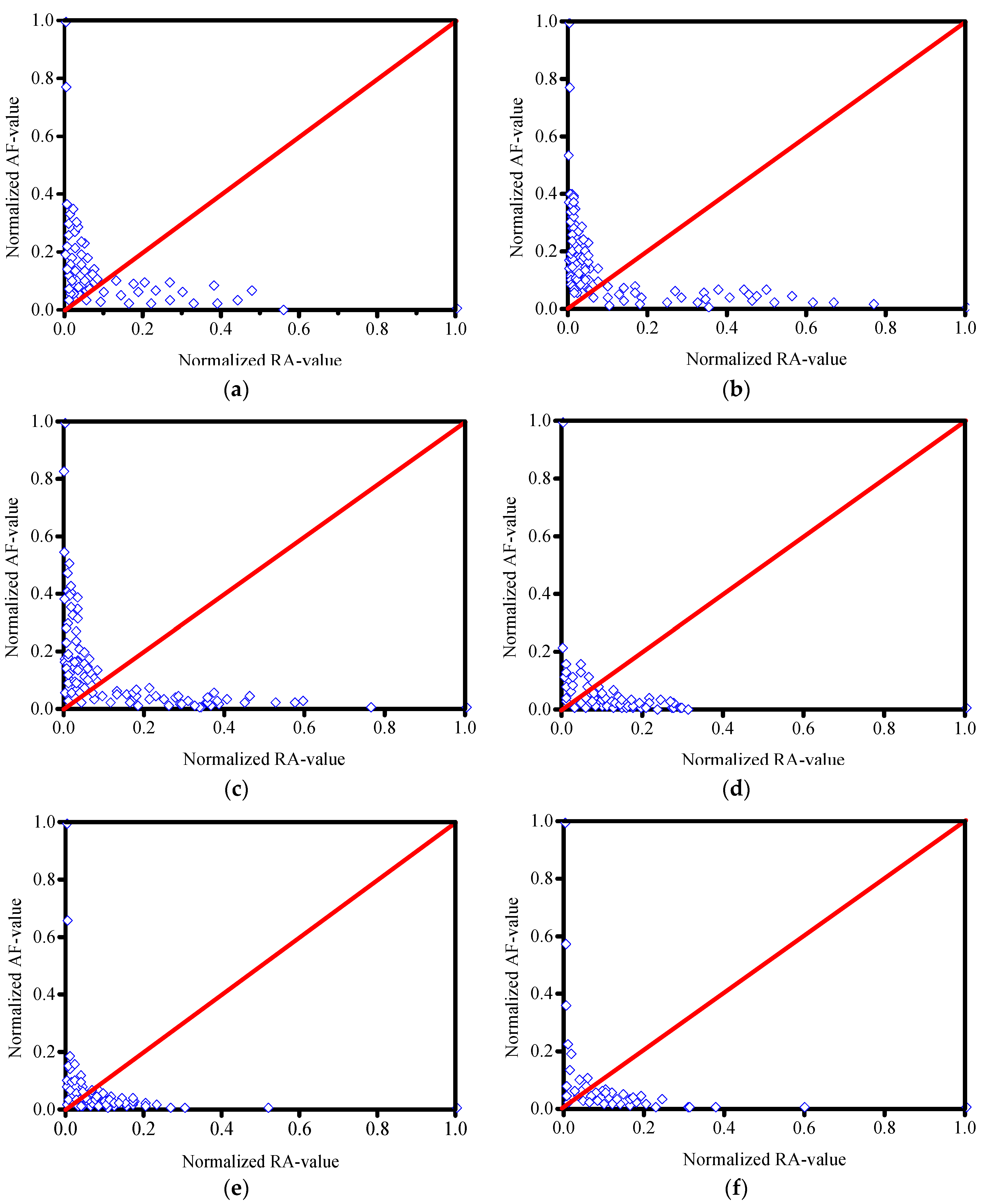
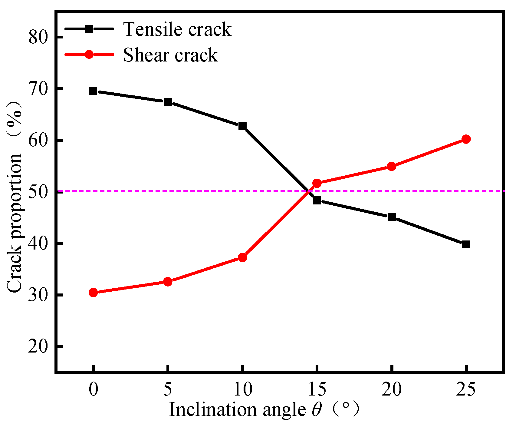
- When the loading rate is 1.0 and 10 mm/min, within the inclination angle of 0°–5°, the proportion of tensile cracks after coal samples failure is significantly greater than that of shear cracks; the tensile failure is the main failure mode of the samples. Within the 10°–25°, the proportion of shear cracks increases gradually with the increase of inclination angle, and both of them are more than 50%. The shear failure is the main failure mode. This law is consistent with the macro failure mode of the samples.
Author Contributions
Funding
Conflicts of Interest
References
- Lunder, P.J.; Pakalnis, R.C. Determination of the strength of hard-rock mine pillars. CIM Bull. 1997, 90, 51–55. [Google Scholar]
- Hedley, D.G.F.; Grant, F. Stope-and-pillar design for the elliot lake uranium mines. CIM Bull. 1972, 65, 37–44. [Google Scholar]
- Salamon, A.H.; Munro, M.D.G. A study of the strength of coal pillars. J. S. Afr. Inst. Min. Metall. 1967, 68, 55–67. [Google Scholar]
- Zhang, Y.; Ren, F.; Zhao, X. Characterization of joint set effect on rock pillars using synthetic rock mass numerical method. Int. J. Geomech. 2017, 17, 06016026. [Google Scholar] [CrossRef]
- Mortazavi, A.; Hassani, F.P.; Shabani, M. A numerical investigation of rock pillar failure mechanism in underground openings. Comput. Geotech. 2009, 36, 691–697. [Google Scholar] [CrossRef]
- Zhang, L.Y.; Deng, K.Z.; Zhu, C.G.; Xing, Z.Q. Analysis of stability of coal pillars with multi-coal seam strip mining. Trans. Nonferrous Metal. Soc. 2011, 21, s549–s555. [Google Scholar] [CrossRef]
- Liu, H.L.; Zhu, W.C.; Yu, Y.J.; Xu, T.; Liu, X.G. Effect of water imbibition on uniaxial compression strength of sandstone. Int. J. Rock Mech. Min. 2020, 127, 104200. [Google Scholar] [CrossRef]
- Wasantha, P.P.L.; Ranjith, G.P.; Viete, R.D.; Luo, L. Influence of the geometry of partially-spanning joints on the uniaxial compressive strength of rock. Int. J. Rock Mech. Min. 2012, 50, 140–146. [Google Scholar] [CrossRef]
- Yang, S.Q.; Dai, Y.H.; Han, L.J.; Jin, Z.Q. Experimental study on mechanical behavior of brittle marble samples containing different flaws under uniaxial compression. Eng. Fract. Mech. 2009, 76, 1833–1845. [Google Scholar] [CrossRef]
- Pan, W.D.; Wang, X.; Liu, Q.M.; Yuan, Y.K.; Zuo, B.D. Non-parallel double-crack propagation in rock-like materials under uniaxial compression. Int. J. Coal Sci. Technol. 2019, 6, 372–387. [Google Scholar] [CrossRef]
- Tsoutrelis, C.E.; Exadaktylos, G.E. Effect of rock discontinuities on certain rock strength and fracture energy parameters under uniaxial compression. Geotech. Geol. Eng. 1993, 11, 81–105. [Google Scholar] [CrossRef]
- Qian, R.P.; Feng, G.R.; Guo, J.; Wang, P.F.; Jiang, H.N. Effects of water-soaking height on the deformation and failure of coal in uniaxial compression. Appl. Sci. 2019, 9, 4370. [Google Scholar] [CrossRef]
- Wang, M.; Wan, W.; Zhao, Y.L. Experimental study on crack propagation and the coalescence of rock-like materials with two preexisting fissures under biaxial compression. Bull. Eng. Geol. Environ. 2020, 79, 3121–3144. [Google Scholar] [CrossRef]
- Wu, C.Z.; Chen, Q.S.; Basack, S.; Xu, R.Q.; Shi, Z.M. Biaxial creep test study on the influence of structural anisotropy on rheological behavior of hard rock. J. Mater. Civil Eng. 2016, 28, 04016104. [Google Scholar] [CrossRef]
- Amann, F.; Kaiser, P.; Button, E.A. Experimental study of brittle behavior of clay shale in rapid triaxial compression. Rock Mech. Rock Eng. 2012, 45, 21–33. [Google Scholar] [CrossRef]
- Geng, Z.; Chen, M.; Jin, Y.; Yang, S.; Yi, Z.C.; Fang, X.; Du, X.Y. Experimental study of brittleness anisotropy of shale in triaxial compression. J. Nat. Gas Sci. Eng. 2016, 36, 510–518. [Google Scholar] [CrossRef]
- Liu, E.L.; He, S.M. Effects of cyclic dynamic loading on the mechanical properties of intact rock samples under confining pressure conditions. Eng. Geol. 2012, 125, 81–91. [Google Scholar] [CrossRef]
- Li, Y.C.; Wu, C.Z.; Jang, B.A. Effect of bedding plane on the permeability evolution of typical sedimentary rocks under triaxial compression. Rock Mech. Rock Eng. 2020, 1–9. [Google Scholar] [CrossRef]
- Yin, Q.; Liu, R.C.; Jing, H.W.; Su, H.J.; Yu, L.Y.; He, L.X. Experimental study of nonlinear flow behaviors through fractured rock samples after high-temperature exposure. Rock Mech. Rock Eng. 2019, 52, 2963–2983. [Google Scholar] [CrossRef]
- Li, G.; Moelle, K.; Lewis, J.A. Fatigue crack growth in brittle sandstones. Int. J. Rock Mech. Min. Sci. Geomech. Abstr. 1992, 29, 469–477. [Google Scholar] [CrossRef]
- Erarslan, N.; Alehossein, H.; Williams, D.J. Tensile fracture strength of brisbane tuff by static and cyclic loading tests. Rock Mech. Rock Eng. 2014, 47, 1135–1151. [Google Scholar] [CrossRef]
- Wu, Q.; Jiang, Y.F.; Tang, H.M.; Luo, H.M.; Wang, X.H.; Kang, J.T.; Zhang, S.; Yi, X.; Fan, L.L. Experimental and numerical studies on the evolution of shear behaviour and damage of natural discontinuities at the interface between different rock types. Rock Mech. Rock Eng. 2020, 53, 3721–3744. [Google Scholar] [CrossRef]
- Yin, Q.; Ma, G.W.; Jing, H.W.; Wang, H.D.; Su, H.J.; Wang, Y.C.; Liu, R.C. Hydraulic properties of 3D rough-walled fractures during shearing: An experimental study. J. Hydrol. 2017, 555, 169–184. [Google Scholar] [CrossRef]
- Li, Y. Test granular materials failure using bi-directional simple shear apparatus: A review. Appl. Sci. 2018, 8, 1140. [Google Scholar] [CrossRef]
- Li, H.T.; Song, L.; Zhou, H.W.; Jiang, Y.D.; Wang, H.W. Evaluation method and application of coal burst performance under the effect of loading rate. J. China Coal Soc. 2015, 40, 21–29. [Google Scholar]
- Zhang, Z.X.; Kou, S.Q.; Yu, J.; Yu, Y.; Jiang, L.G.; Lindqvist, P.A. Effects of loading rate on rock fracture. Int. J. Rock Mech. Min. 1999, 36, 597–611. [Google Scholar] [CrossRef]
- Hou, Z.K.; Gutierrez, M.; Ma, S.Q.; Almrabat, A.; Yang, C.H. Mechanical behavior of shale at different strain rates. Rock Mech. Rock Eng. 2019, 52, 3531–3544. [Google Scholar] [CrossRef]
- Lajtai, E.Z.; Duncan, E.J.S.; Carter, B.J. The effect of strain rate on rock strength. Rock Mech. Rock Eng. 1991, 24, 99–109. [Google Scholar] [CrossRef]
- Wasantha, P.L.P.; Ranjith, P.G.; Zhao, J.; Shao, S.S.; Permata, G. Strain rate effect on the mechanical behaviour of sandstones with different grain sizes. Rock Mech. Rock Eng. 2015, 48, 1883–1895. [Google Scholar] [CrossRef]
- Alam, M.S.; Chakraborty, T.; Matsagar, V.; Rao, K.S.; Sharma, P.; Singh, M. Characterization of kota sandstone under different strain rates in uniaxial loading. Geotech. Geol. Eng. 2015, 33, 143–152. [Google Scholar] [CrossRef]
- Okubo, S.; Nishimatsu, Y.; He, C. Loading rate dependence of class ii rock behaviour in uniaxial and triaxial compression tests—An application of a proposed new control method. Int. J. Rock Mech. Min. Sci. Geomech. Abstr. 1990, 27, 559–562. [Google Scholar] [CrossRef]
- Li, H.T.; Zhou, H.W.; Jiang, Y.D.; Wang, H.W. An evaluation method for the bursting characteristics of coal under the effect of loading rate. Rock Mech. Rock Eng. 2016, 49, 3281–3291. [Google Scholar]
- Li, H.M.; Li, H.G.; Gao, B.B.; Jiang, D.J.; Feng, J.F. Study of acoustic emission and mechanical characteristics of coal samples under different loading rates. Shock Vib. 2015, 2015, 1–11. [Google Scholar] [CrossRef]
- Baker, W.E.; Yew, C.H. Strain-rate effects in the propagation of torsional plastic waves. J. Appl. Mech. 1966, 33, 917. [Google Scholar] [CrossRef]
- Huang, H.; Feng, R. A study of the dynamic tribological response of closed fracture surface pairs by kolsky-bar compression-shear experiment. Int. J. Solids Struct. 2004, 41, 2821–2835. [Google Scholar] [CrossRef]
- Xu, Y.; Dai, F. Dynamic response and failure mechanism of brittle rocks under combined compression-shear loading experiments. Rock Mech. Rock Eng. 2017, 51, 747–764. [Google Scholar] [CrossRef]
- Nie, X.; Chen, W. Dynamic failure of a borosilicate glass under compression/shear loading. In Proceedings of the Ceramic Engineering and Science Proceedings, 31st International Conference on Advanced Ceramics and Composites, Daytona Beach, FL, USA, 21–26 January 2007; pp. 103–111. [Google Scholar]
- Xin, S.; Liu, W.N.; Chen, W.N.; Templeton, D. Modeling and characterization of dynamic failure of borosilicate glass under compression/shear loading. Int. J. Impact Eng. 2009, 36, 226–234. [Google Scholar]
- Brown, E.T. The ISRM Suggested Methods for Rock Characterization, Testing and Monitoring: 2007–2014; Ulusay, R., Ed.; Springer International Publishing: Cham, Switzerland, 2015; p. 293. [Google Scholar]
- Chen, L.; Wu, P.; Chen, Y.L.; Zhang, W. Experimental study on physical-mechanical properties and fracture behaviors of saturated yellow sandstone considering coupling effect of freeze-thaw and specimen inclination. Sustainability 2020, 12, 1029. [Google Scholar] [CrossRef]
- Chen, L.; Mao, X.B.; Wu, P. Temperature and inclination angle on mechanical properties and fracture behavior of granite at low strain rate. Sustainability 2020, 12, 1255. [Google Scholar] [CrossRef]
- Ohtsu, M.; Tomoda, Y.; Suzuki, T. Damage evaluation and corrosion detection in concrete by acoustic emission. In Fracture Mechanics of Concrete and Concrete Structure-Design; Carpinteri, A., Gambarova, P.G., Ferro, G., Plizzari, G., Eds.; Taylor and Francis Group: London, UK, 2007. [Google Scholar]
- Aggelis, D.G.; Sapouridis, S.D.V. Characterization of the Damage Process in Fibre Reinforced Concrete Using Acoustic Emission Parameters. In Proceedings of the Structural Faults and Repair, Edinburgh, UK, 15–17 June 2010; pp. 15–17. [Google Scholar]
- Kim, J.S.; Lee, K.S.; Cho, W.J.; Choi, H.J.; Cho, G.C. A comparative evaluation of stress-strain and acoustic emission methods for quantitative damage assessments of brittle rock. Rock Mech. Rock Eng. 2015, 48, 495–508. [Google Scholar] [CrossRef]
- Zhao, X.G.; Cai, M.; Wang, J.; Li, P.F.; Ma, L.K. Objective determination of crack initiation stress of brittle rocks under compression using ae measurement. Rock Mech. Rock Eng. 2015, 48, 2473–2484. [Google Scholar] [CrossRef]
- Wang, X.; Wen, Z.J.; Jiang, Y.J.; Huang, H. Experimental study on mechanical and acoustic emission characteristics of rock-like material under non-uniformly distributed loads. Rock Mech. Rock Eng. 2017, 51, 729–745. [Google Scholar] [CrossRef]
- Shahidan, S.; Pulin, R.; Bunnori, N.M.; Holford, K.M. Damage classification in reinforced concrete beam by acoustic emission signal analysis. Constr. Build. Mater. 2013, 45, 78–86. [Google Scholar] [CrossRef]
- Kahraman, S. Evaluation of simple methods for assessing the uniaxial compressive strength of rock. Int. J. Rock Mech. Min. 2001, 38, 981–994. [Google Scholar] [CrossRef]
- He, Q.Y.; Li, Y.C.; She, S. Mechanical properties of basalt specimens under combined compression and shear loading at low strain rates. Rock Mech. Rock Eng. 2019, 52, 4101–4112. [Google Scholar] [CrossRef]
- Walsh, J.B. The effect of cracks on the uniaxial elastic compression of rocks. J. Geophys. Res. 2012, 70, 399–411. [Google Scholar] [CrossRef]
- Bieniawski, Z.T. Mechanism of brittle fracture of rock: Part I—Theory of the fracture process. Int. J. Rock Mech. Min. Sci. Geomech. Abstr. 1967, 4, 395. [Google Scholar] [CrossRef]
- Benz, T.; Schwab, R. A quantitative comparison of six rock failure criteria. Int. J. Rock Mech. Min. 2008, 45, 1176–1186. [Google Scholar] [CrossRef]
- He, Q.Y.; Li, Y.C.; Xu, J.H.; Zhang, C.G. Prediction of mechanical properties of igneous rocks under combined compression and shear loading through statistical analysis. Rock Mech. Rock Eng. 2020, 53, 841–859. [Google Scholar] [CrossRef]
- Khanlari, G.; Sahamieh, R.Z.; Abdilor, Y. The effect of freeze—Thaw cycles on physical and mechanical properties of upper red formation sandstones, central part of iran. Arab. J. Geosci. 2015, 8, 5991–6001. [Google Scholar] [CrossRef]
- Han, T.; Shi, J.; Cao, X. Fracturing and damage to sandstone under coupling effects of chemical corrosion and freeze—Thaw cycles. Rock Mech. Rock Eng. 2016, 49, 1–11. [Google Scholar] [CrossRef]


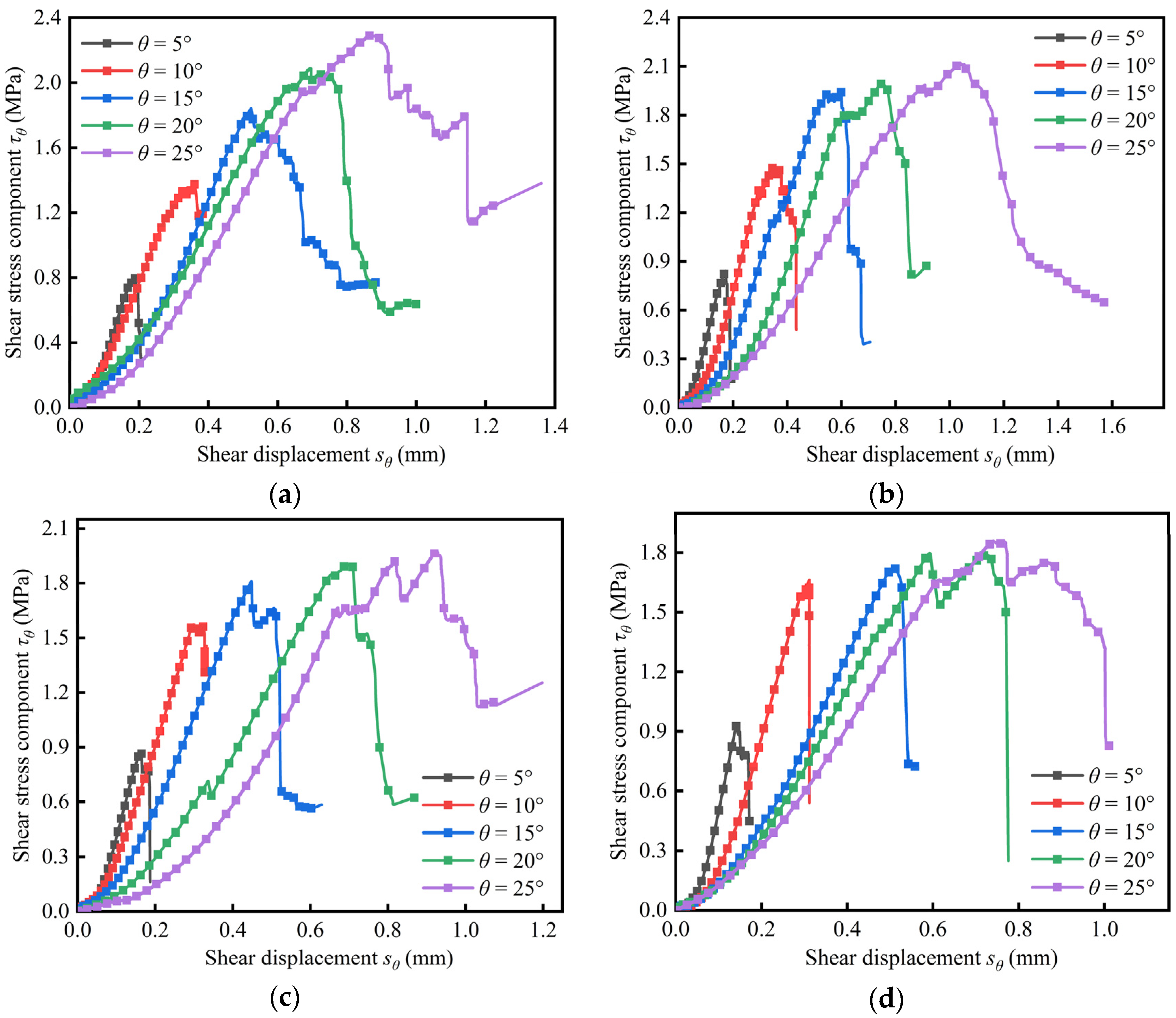
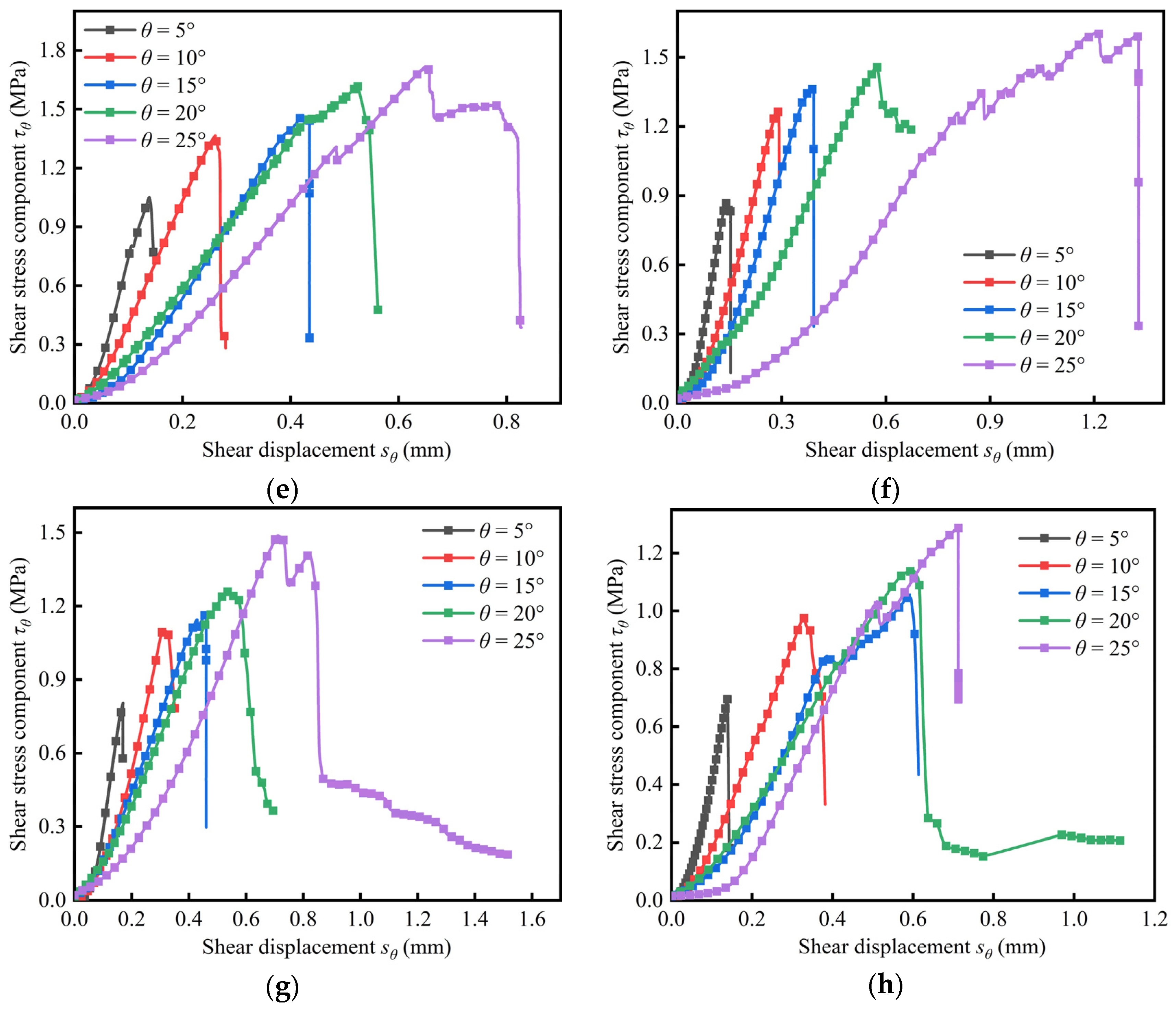
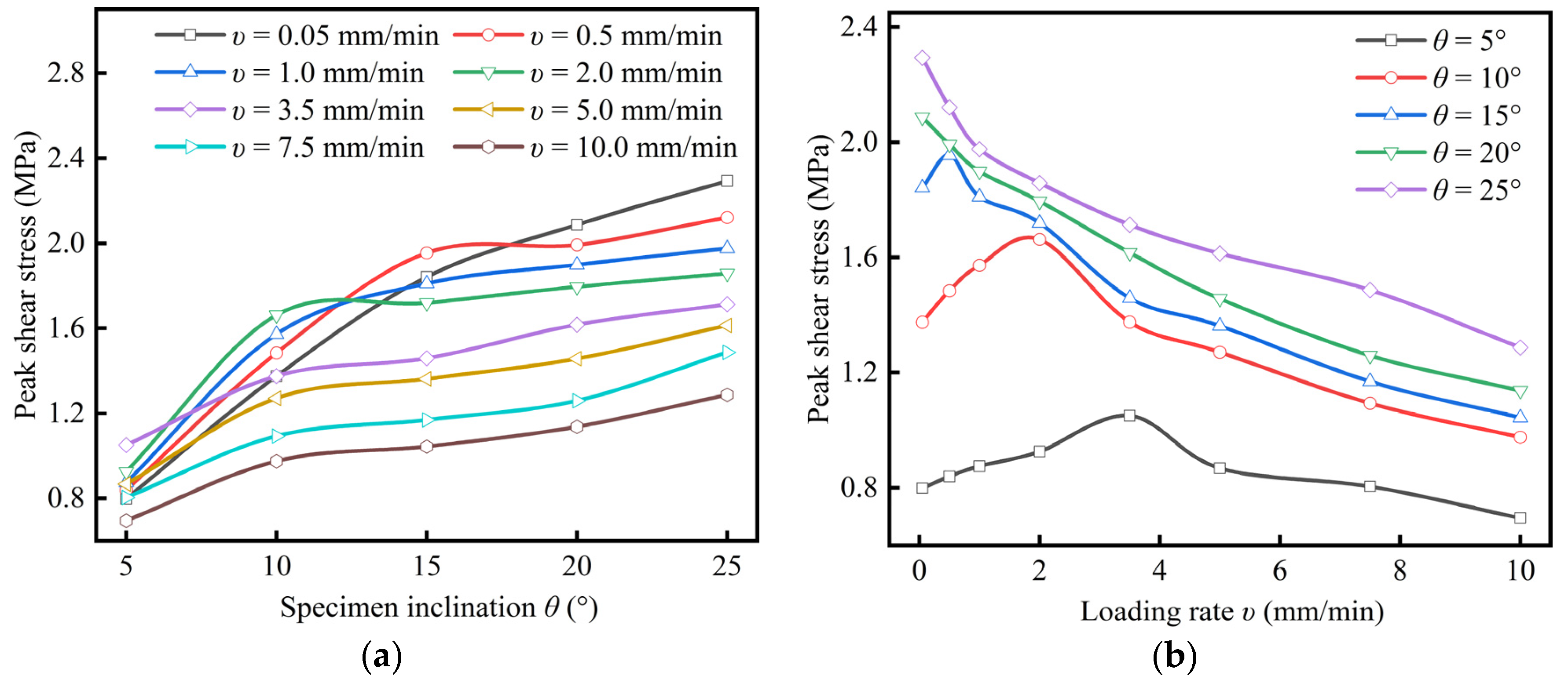



| Inclination Angles θ (°) | Loading Rate (mm/min) | |||||||
|---|---|---|---|---|---|---|---|---|
| 0.05 | 0.5 | 1 | 2 | 3.5 | 5 | 7.5 | 10 | |
| 5 | 0.80 | 0.84 | 0.87 | 0.93 | 1.05 | 0.87 | 0.80 | 0.69 |
| 10 | 1.37 | 1.48 | 1.57 | 1.66 | 1.38 | 1.27 | 1.09 | 0.97 |
| 15 | 1.84 | 1.95 | 1.81 | 1.72 | 1.46 | 1.36 | 1.17 | 1.04 |
| 20 | 2.09 | 1.99 | 1.90 | 1.79 | 1.62 | 1.46 | 1.26 | 1.14 |
| 25 | 2.29 | 2.12 | 1.98 | 1.86 | 1.71 | 1.61 | 1.49 | 1.29 |
| Inclination Angle (°) | Loading Rate (mm/min) | Peak Axial Stress (MPa) | Absolute Error (MPa) | Relative Error (%) | Average Peak Axial Stress (MPa) | Standard Deviation (MPa) | Relative Standard Deviation (%) |
|---|---|---|---|---|---|---|---|
| 0 | 0.05 | 10.16 | 1.10 | 12.15 | 9.06 | 1.00 | 11.07 |
| 8.19 | 0.86 | 9.51 | |||||
| 8.82 | 0.24 | 2.64 | |||||
| 5 | 0.05 | 10.60 | 1.11 | 11.67 | 9.49 | 0.99 | 10.38 |
| 8.71 | 0.78 | 8.19 | |||||
| 9.16 | 0.33 | 3.48 | |||||
| 10 | 10.00 | 6.88 | 0.63 | 10.04 | 6.25 | 0.63 | 10.12 |
| 6.26 | 0.01 | 0.16 | |||||
| 5.61 | 0.64 | 10.19 | |||||
| 15 | 2.00 | 7.23 | 0.68 | 10.35 | 6.55 | 0.73 | 11.13 |
| 5.78 | 0.77 | 11.78 | |||||
| 6.64 | 0.09 | 1.42 | |||||
| 20 | 0.50 | 5.06 | 0.66 | 11.47 | 5.72 | 0.61 | 10.67 |
| 6.27 | 0.55 | 9.62 | |||||
| 5.82 | 0.11 | 1.85 | |||||
| 25 | 3.50 | 3.41 | 0.48 | 12.46 | 3.89 | 0.43 | 10.98 |
| 4.21 | 0.32 | 8.28 | |||||
| 4.05 | 0.16 | 4.18 |
| Inclination Angle (°) | Loading Rate (mm/min) | Elasticity Modulus (MPa) | Absolute Error (MPa) | Relative Error (%) | Average Elasticity Modulus (MPa) | Standard Deviation (MPa) | Relative Standard Deviation (%) |
|---|---|---|---|---|---|---|---|
| 0 | 3.5 | 1067.87 | 49.00 | 4.81 | 1018.87 | 46.91 | 4.60 |
| 974.37 | 44.50 | 4.37 | |||||
| 1014.38 | 4.50 | 0.44 | |||||
| 5 | 7.5 | 746.56 | 43.04 | 5.45 | 789.59 | 37.36 | 4.73 |
| 813.73 | 24.14 | 3.06 | |||||
| 808.49 | 18.90 | 2.39 | |||||
| 10 | 0.05 | 558.21 | 30.26 | 5.73 | 527.95 | 33.88 | 6.42 |
| 491.35 | 36.60 | 6.93 | |||||
| 534.29 | 6.34 | 1.20 | |||||
| 15 | 10.0 | 330.67 | 14.96 | 4.74 | 315.70 | 13.81 | 4.37 |
| 303.46 | 12.25 | 3.88 | |||||
| 312.99 | 2.72 | 0.86 | |||||
| 20 | 3.5 | 348.72 | 23.45 | 6.30 | 372.16 | 20.73 | 5.57 |
| 388.06 | 15.90 | 4.27 | |||||
| 379.71 | 7.55 | 2.03 | |||||
| 25 | 0.05 | 362.81 | 23.62 | 6.11 | 386.43 | 21.11 | 5.46 |
| 403.45 | 17.01 | 4.40 | |||||
| 393.04 | 6.61 | 1.71 |
| Loading Rate (mm/min) | Inclination (°) | Failure Mode | Failure Mechanism |
|---|---|---|---|
| 0.05–0.50 | 0–5 | The sample is relatively complete, and one or more longitudinal cracks can be seen on the surface. | Tensile failure (dominant) |
| 10 | Splitting cracks approximately parallel to the axial direction of the samples are generated on the surface of most coal samples, accompanied by a large number of shear cracks. | Tension–shear composite failure | |
| 15–25 | The macroscopic failure surfaces with a certain angle to the axial direction of the sample are developed on the surface, and the failure degree of the sample is relatively small | Shear failure (dominant) | |
| 1.0–5.0 | 0–5 | Axial splitting failure, but the integrity of coal samples was destroyed, and some pieces and debris were stripped around | Tensile failure (dominant) |
| 10 | Splitting cracks and shear cracks are widely developed on the surface of coal sample | Tension–shear composite failure | |
| 15–25 | The macroscopic failure surfaces with a certain angle to the axial direction of the sample are developed on the surface, and the failure degree of the sample is further increased | Shear failure (dominant) | |
| 7.5–10.0 | 0–5 | Conical failure (dominant). The sample has poor integrity, with more fragments, showing bursting characteristics. | Tensile failure (dominant) |
| 10 | Splitting cracks approximately parallel to the axial direction of the samples are generated on the surface of most coal samples, accompanied by a large number of shear cracks. Axial splitting is transformed into shear slipping failure | Tension–shear composite failure | |
| 15–25 | The macroscopic failure surfaces with a certain angle to the axial direction of the sample are developed on the surface, and the integrity of the sample is destroyed | Shear failure (dominant) |
| Inclination Angle (°) | Tensile Crack/Total Crack (%) | Shear Crack/Total Crack (%) |
|---|---|---|
| 0 | 57.96 | 42.04 |
| 5 | 55.78 | 44.22 |
| 10 | 42.48 | 57.52 |
| 15 | 36.87 | 63.13 |
| 20 | 26.03 | 73.97 |
| 25 | 22.65 | 77.35 |
| Inclination Angle (°) | Tensile Crack/Total Crack (%) | Shear Crack/Total Crack (%) |
|---|---|---|
| 0 | 69.56 | 30.44 |
| 5 | 67.46 | 32.54 |
| 10 | 62.75 | 37.25 |
| 15 | 48.35 | 51.65 |
| 20 | 45.05 | 54.95 |
| 25 | 39.81 | 60.19 |
© 2020 by the authors. Licensee MDPI, Basel, Switzerland. This article is an open access article distributed under the terms and conditions of the Creative Commons Attribution (CC BY) license (http://creativecommons.org/licenses/by/4.0/).
Share and Cite
Chen, Y.; Cui, H.; Pu, H.; Wu, P.; Chen, L.; Zhang, K. Study on Mechanical Properties and Cracking Mode of Coal Samples under Compression–Shear Coupled Load Considering the Effect of Loading Rate. Appl. Sci. 2020, 10, 7082. https://doi.org/10.3390/app10207082
Chen Y, Cui H, Pu H, Wu P, Chen L, Zhang K. Study on Mechanical Properties and Cracking Mode of Coal Samples under Compression–Shear Coupled Load Considering the Effect of Loading Rate. Applied Sciences. 2020; 10(20):7082. https://doi.org/10.3390/app10207082
Chicago/Turabian StyleChen, Yanlong, Huidong Cui, Hai Pu, Peng Wu, Liang Chen, and Kai Zhang. 2020. "Study on Mechanical Properties and Cracking Mode of Coal Samples under Compression–Shear Coupled Load Considering the Effect of Loading Rate" Applied Sciences 10, no. 20: 7082. https://doi.org/10.3390/app10207082
APA StyleChen, Y., Cui, H., Pu, H., Wu, P., Chen, L., & Zhang, K. (2020). Study on Mechanical Properties and Cracking Mode of Coal Samples under Compression–Shear Coupled Load Considering the Effect of Loading Rate. Applied Sciences, 10(20), 7082. https://doi.org/10.3390/app10207082


