Article

Seismic Effectiveness of Multiple Seismic Measures on a Continuous Girder Bridge

1
Mechanical Engineering College, Xi’an Shiyou University, Xi’an 710065, China
2
School of Human Settlement and Civil Engineering, Xi’an Jiaotong University, Xi’an 710049, China
*
Author to whom correspondence should be addressed.
Appl. Sci. 2020, 10(2), 624; https://doi.org/10.3390/app10020624
Submission received: 21 November 2019 / Revised: 9 January 2020 / Accepted: 10 January 2020 / Published: 15 January 2020

Abstract

:
Seismic hazards, such as bridge pounding, unseating, collapse, etc., cause significant economic losses and affect traffic and safety. Research on seismic measures, such as limiting and unseating prevention devices for the bridge, can effectively prevent damage to the bearings, such as excessive displacement, the pounding of the beam end, etc., in an earthquake. In this paper, the dynamic time-history analysis method was used to study the mechanical behaviors of the bridge structure, such as its seismic performance, structural displacement, pier bending moment, etc. We found that different combinations of seismic measures can effectively reduce the displacement at the bridge expansion joint and bearings. The joint application of an expansion device, restrainer, and unseating prevention devices shows the best limiting effect on bridge displacement and expansion joint displacement. The maximum reduction of bridge expansion joint displacement reaches 48% and is within the allowable deformation range of an expansion device in a large earthquake, and the maximum reduction of bearing displacement reaches 34%, which only slightly exceeds the shear deformation of the bearing. The expansion device, restrainer, and unseating prevention devices have smaller internal forces in this case than other cases, without damage. In contrast to the previous studies on single seismic measures of unseating restrainers, this study investigates the combination of multiple seismic measures and earthquakes of various magnitude. It reveals the catastrophe process of the bridge structure and the cooperation law of seismic measures in an earthquake.

1. Introduction

In recent years, many bridges have become damaged, even by pounding and unseating, due to the failure of bearings and the pounding between adjacent structures during earthquakes. These incidents cause significant economic losses and many casualties [1,2,3,4,5,6]. Therefore, it is essential to explore new seismic measures to prevent the pounding, unseating, and collapse of bridges in earthquake-prone countries.
The researchers used experiments [7,8] and numerical simulation techniques to study different seismic measures, such as concrete shear keys [9,10,11], steel bar restrainers [12,13], cable restrainers [7,14], viscoelastic dampers, and innovative devices [15,16]. Numerical simulation techniques (including quasi-static [17,18,19], the seismic design method [20,21,22], and dynamic simulation [23,24,25,26]) are widely used for anti-seismic research on the prevention of pounding and unseating because of their advantages that they consume few resources and acquire a large amount of physical information.
Saiidi et al. [17] investigated four bridges retrofitted with seismic measures during the 1989 Loma Prieta earthquake. They found that measures are effective to reduce the displacement of the bridge and are generally capable of reducing the intensity of impact between two adjacent decks. DesRoches et al. [18,19] carried out a series of full-scale tests of a simply-supported bridge to evaluate the force–displacement behavior of the cable restrainers. They found that the inadequate performance of restrainers during large earthquakes remained elastic. Li et al. [21] proposed a displacement-based seismic design method for cable restrainers in a three-span simply supported highway bridge; the behavior of cable restrainers was modeled using a tension-only elastic element with a gap/slack. The results show that the restrainers could remain functional and limit the relative displacement within a design value during earthquakes. Guo et al. [26] studied a multidirectional cable restrainer on the seismic fragility of a curved bridge, and their results indicate that multidirectional cable restrainers can remarkably decrease the failure probability of a bridge subjected to a strong earthquake, and that a pier with fixed bearings will experience severe axial forces. Some researchers compared the seismic performance of seismic measures in limiting the relative displacements of the bridge; the studies indicated that all the devices could control the bearing deformation to a safe limit if they were designed correctly [27,28]. Another mitigation measure for the pounding of adjacent structures would be the prevention of impact incidents by providing sufficient gaps. However, the size of expansion joints has to be limited for smooth traffic flow, making the adjacent structures susceptible to earthquake-induced poundings [29]. The incorporation of layers of soft material on the expansion joints to act as shock absorbers has been suggested; previous studies have assessed the effectiveness of this impact mitigation measure on the response of bridges and buildings [30].
Researchers have studied the single factor of seismic measures and the effectiveness of seismic measures for preventing bridge pounding and collapse in an earthquake. However, the combination of multiple seismic measures is seldom considered, and the seismic effects of a single seismic measure and multiple seismic measures are rarely compared [31].
Kawashima and Shoji [29] revealed that a rubber bumper, along with restrainers at the bridge joint, was not only effective in reducing joint acceleration and relative joint displacements but also reduced the response of the bridge piers to some extent. Zhu et al. [32] proposed applying shock-absorbing devices along with restrainers to counter pounding effects and to improve the serviceability of elevated bridges during a seismic event; their results indicated that rubber shock-absorbing devices were effective in mitigating the impact forces as well as the acceleration impulse caused by pounding. Abdel [14] investigated three different configurations of a hybrid device with a rubber bumper and restrainers to prevent unseating and mitigate the pounding effect at the expansion joint of isolated multi-span bridges, and the results showed that restrainers are substantially effective at reducing the relative displacements and impact forces due to pounding at the expansion joints. The sudden changes of stiffness during poundings can be smoothed by using a natural rubber shock absorber, which prevents the acceleration peaks due to impact. Shrestha et al. [33] discussed the merits and limitations of various pounding and unseating mitigation devices that have been proposed by multiple researchers, and the application of rubber bumpers with restrainers and the combination of dampers with restrainers has received considerable attention in applications to reduce the damages as well as improve the serviceability of the bridge.
The above research shows that, under the action of multi-factor coupling, the influence of seismic load on various measures is not a simple linear superposition, which also means that the effectiveness of different coupling measures on the seismic response of bridges is diverse and complex. A satisfactory aspect is that it provides specific stiffness against service-level loads, dissipates substantial energy during moderate earthquakes, and prevents collapse during a strong earthquake [34,35].
This paper focuses on the seismic effectiveness of multiple seismic measures (such as expansion devices, restrainers, and unseating prevention devices) on preventing unseating, pounding, and collapse damage to a continuous girder bridge under earthquakes of various magnitudes to reveal the catastrophe process of the bridge structure and the cooperation law of seismic measures in an earthquake.

2. Theoretical Pounding Analysis of a Bridge

The pounding process of bridges is usually described in two stages:
(1)
Initially, there is no pounding between the structures, and the pounding stiffness can be regarded as zero.
(2)
When the ends are pounding, the pounding stiffness will no longer be zero. If seismic measures are adopted on the bridge, the pounding stiffness will be the stiffness of the control measures.
In this paper, m is the mass of the superstructure, k is the pounding stiffness, and c is the damping at the time of the structural pounding. The variables x ( t ) , x ˙ ( t ) , x ¨ ( t ) are the displacement, velocity, and acceleration of the structure relative to the ground, respectively, which are all functions of time t . Assuming that the pounding occurs at time t = 0 and finishes at time t 0 , the motion equation of the structure is as follows:
{ m x ¨ + c x ˙ + k x = 0 x ( 0 ) = 0 x ˙ ( 0 ) = v 0 ,
where x ( 0 ) and x ˙ ( 0 ) are the structural displacement and velocity at time t = 0 .
The solution of the equation is
x ( t ) = A exp ( ξ ω ¯ n t ) sin ( ω ¯ d t ) ,
where A = v 0 ω ¯ d , ω ¯ n = k m , and ω ¯ d = ω ¯ n 1 ξ 2 . ω ¯ n is the natural frequency of the structure, ω ¯ d is the natural frequency of the structure with damping, and ξ is the damping ratio.
According to the boundary conditions of the pounding x ¨ ( t 0 ) = 0 , the pounding time can be calculated as follows:
t 0 = π a r c t a n λ ω ¯ n 1 ξ 2 ,
where λ = 2 1 ξ 2 1 2 ξ 2 .
If we substitute x ¨ ( t 0 ) = 0 into Equation (1), the equation becomes
c x ˙ ( t 0 ) + k x ( t 0 ) = 0 .
The velocity after the pounding x ˙ ( t 0 ) can be calculated by solving the following equation:
x ˙ ( t 0 ) = v 0 1 2 ξ 2 exp [ ξ 1 ξ 2 ( π arctan λ ) ] · cos ( π arctan λ ) .
The velocity ratio before and after the pounding is
e = x ˙ ( t 0 ) v 0 = 1 1 2 ξ 2 exp [ ξ 1 ξ 2 ( π arctan λ ) ] · cos ( π arctan λ ) .
As the average impact force is F ¯ , according to the momentum theorem, the relationship between the average pounding force and velocity is as follows:
F ¯ t 0 = m · ( v 0 x ˙ ( t 0 ) ) = m v 0 ( 1 e ) .
As A = v 0 ω ¯ d , ω ¯ n = k m , and ω ¯ d = ω ¯ n 1 ξ 2 , the average pounding force can calculated by solving the following equation:
F ¯ = m · v 0 ( 1 e ) t 0 = m v 0 t 0 { 1 1 1 2 ξ 2 exp [ ξ 1 ξ 2 ( π arctan λ ) ] · cos ( π arctan λ ) } = m · ω ¯ d A · ω ¯ n 1 ξ 2 π arctan λ { 1 1 1 2 ξ 2 exp [ ξ 1 ξ 2 ( π arctan λ ) ] · cos ( π arctan λ ) } = m · ω ¯ n 1 ξ 2 A · ω ¯ n 1 ξ 2 π arctan λ { 1 1 1 2 ξ 2 exp [ ξ 1 ξ 2 ( π arctan λ ) ] · cos ( π arctan λ ) } = A k · ( 1 ξ 2 ) π arctan 2 1 ξ 2 1 2 ξ 2 { 1 1 1 2 ξ 2 exp [ ξ 1 ξ 2 ( π arctan 2 1 ξ 2 1 2 ξ 2 ) ] · cos ( π arctan 2 1 ξ 2 1 2 ξ 2 ) } .
It is evident from Equation (8) that the average impact force F ¯ in the pounding process is a function of the damping ratio ξ and stiffness k [21]. Therefore, when preventing bridge pounding, controlling the stiffness and damping of the structure will influence the pounding force.

3. Establishment of a Finite Element Model of a Bridge

3.1. Description of the Bridge

A four-span continuous girder bridge is studied to evaluate the effect of seismic measures. The bridge has a single span of 30 m and a total span of 120 m, as shown in Figure 1a. Figure 1b shows the section of the girder, which consists of six small box girders with either reinforced or pre-stressed concrete, with a width of 17 m and a height of 1.6 m. The compressive strength of concrete used in the girder is 50 MPa, the elastic modulus is 34,500 MPa, and the bulk density is 25 kN/m3 [21]. The piers of the bridge have a square cylindrical section, with a height of 15 m and a side length of 1.8 m, as shown in Figure 1c. The compressive strength of concrete used in piers is 30 MPa, the elastic modulus is 30,000 MPa, and the bulk density is 25 kN/m3. The total weight of the bridge is 8137 kN [25]. The girder and pier of the bridge are modelled using the elastic beam–column elements. The pier foundation is assumed to be fixed and the soil structure interaction is neglected.
The bearings adopted on #1 and #5 piers and #2, #3, and #4 piers are different. Slide rubber bearings are adopted on #1 and #5 piers, in order to satisfy the deformation requirements of the structure under a static load, whereas laminated rubber bearings are adopted on #2, #3, and #4 piers. The bearings consisting of an elastomeric rubber pad are modelled by the elastic, perfectly plastic element to represent the frictional force developed at the elastomeric pad. The parameters of the bearings are shown in Table 1 [36].
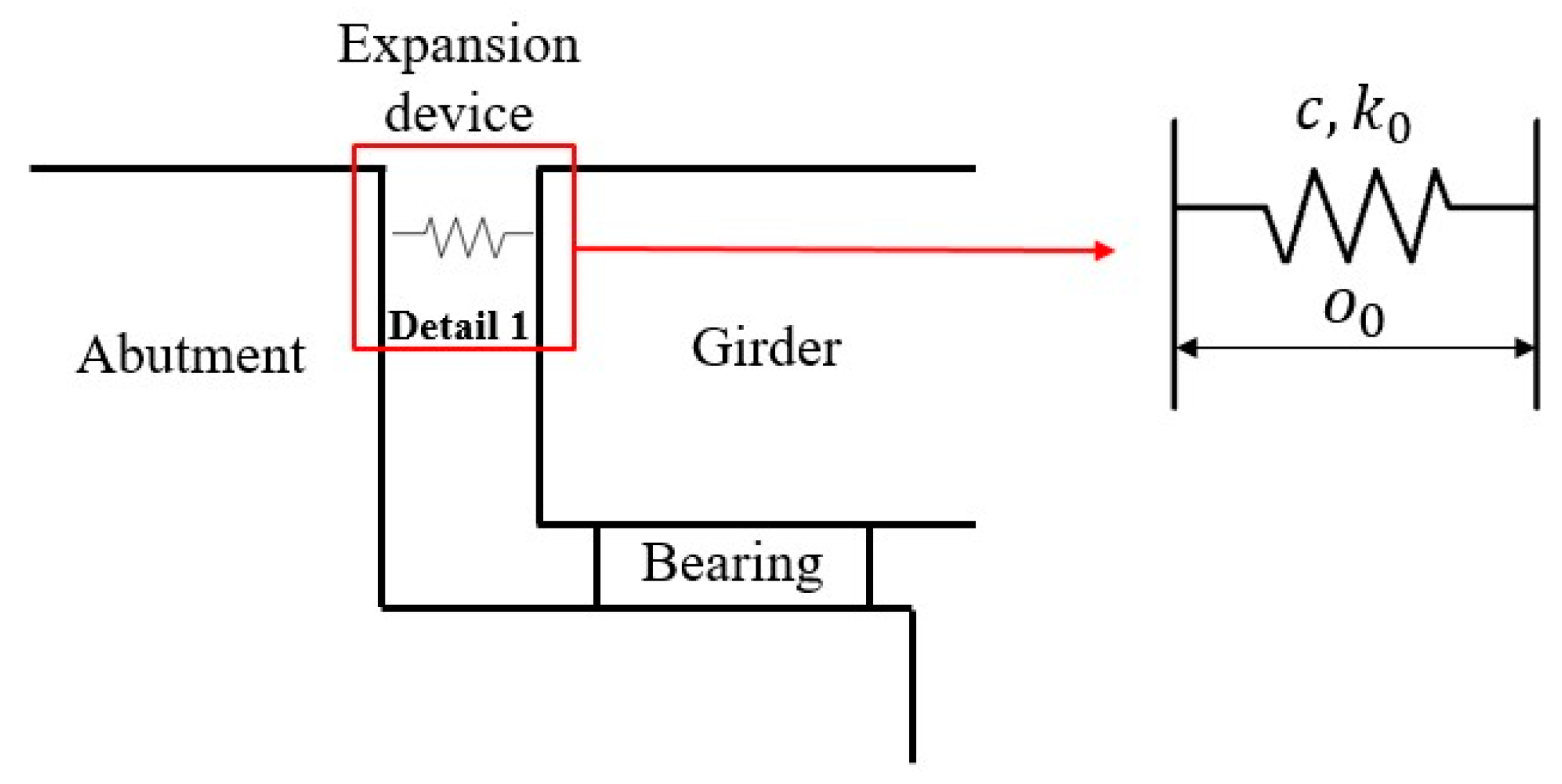
The initial gap of expansion device is 160 mm, as shown in Figure 2. The steel members of the expansion device have a yield strength of 345 MPa and an ultimate strength range of 490–675 MPa. The lower limit of tensile strength of rubber shear springs is 20 MPa [32]. The expansion devices are modelled by the clearance element: the clearance quantity is the same as initial gap, 160 mm, the effective stiffness is 5320 kN/mm, and the damping c is 5.16 kN·s/m, with the ultimate impact as 15,000 kN [37].
High-strength steel bars or cables are desirable options for unseating prevention restrainers, which can generally be implemented in the longitudinal direction of bridges, unlike concrete shear keys. They can be installed at either end abutments, intermediate piers, or in-span hinges, and such applications have proved effective at reducing the likelihood of bridge unseating [27]. As steel cable/bar restrainers are the least expensive option, they are extensively used as bridge unseating prevention restrainers.
Therefore, this study selects high-strength steel bars as restrainers and steel cables as unseating prevention devices.

3.2. Simulation of the Bridge and Seismic Measures

3.2.1. Finite Element Model of the Bridge

A finite element model of the bridge was established, in which the girder, bent cap, and piers are simulated by finite elements using beam elements, and the bearings were simulated by an elastic connection [38]. The gap element was selected for the simulation of the expansion device.

3.2.2. Finite Element Model of Restrainer

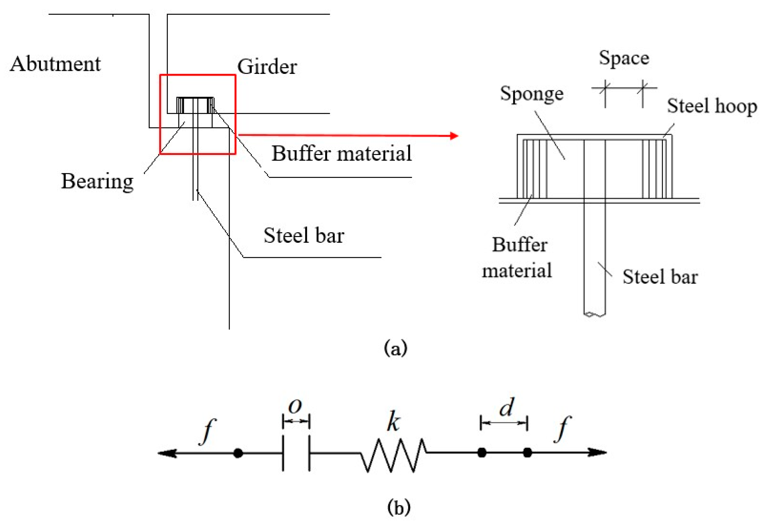
Many measures restrict the large displacement of bridges, such as restrainer and unseating prevention devices [14]. Restrainers can be used to restrict the displacement of the bearing within an allowable deformation; thus, such a device is selected to control large displacements between the superstructure and substructure of a bridge. The steel bar was selected as the restrainer in this study, and its structural diagram is shown in Figure 3a. The material of the steel restrainer bar has a yield strength of 335 MPa and the elastic modulus of 200 GPa. The restrainer details are described in Liu et al. [12].
The steel cable restrainers are modelled by using the tension-only bilinear elements. Considering that the initial design space of the restrainer needs to provide enough common deformation space for bearings, the initial design space o was selected to be the same as the displacement of bearings under a small earthquake, which is 38 mm, and the stiffness k was selected to be 104 kN/m. The restrainers were set on #1 and #5 piers [12,35].
The gap element in the finite element program was used to simulate the restrainer; hence, simultaneously considering the design parameters such as initial design space and stiffness, the finite element model of the device is as shown in Figure 3b. When the relative displacement between the superstructure and the substructures d on one side of the bridge exceeds the initial design space of the restrainer o , the restrainer on this site will be activated:
  • o is the initial design space of the restrainer,
  • d is the relative displacement of the superstructure and substructures of the bridge,
  • k is the stiffness of the restrainer,
  • f is the force of the restrainer, the value of which can calculated according to Equation (9):
    f = { k ( d + o ) 0 ( d + o 0 d + o > 0 ) .

3.2.3. Selection and Simulation of Unseating Prevention Devices

When the seismic load exceeds the designed strength, and the restrainer is insufficient to control the excessive displacement of the bridge, the unseating prevention device is an effective control measure to prevent the pounding between girders caused by bearing failure and the damage caused by falling.
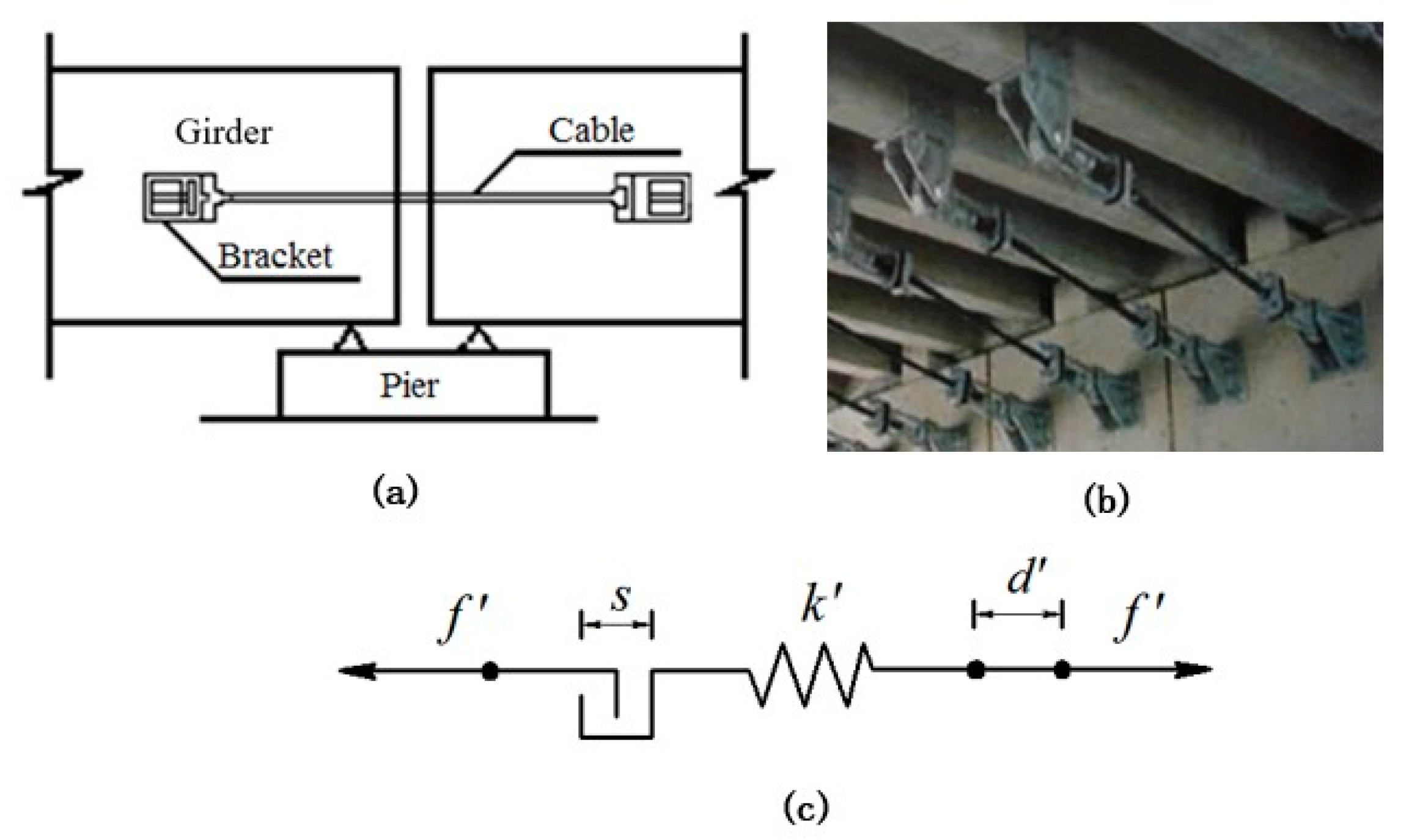
There are various unseating prevention measures in bridges, such as steel plates, connecting bars, cables, and pre-stress wires. Compared to the other devices, cables have better applicability, and their initial space is controllable. Thus, a cable unseating prevention device was selected for this study [39], as shown in Figure 4.
The hoop element in the finite element program was used to simulate the unseating prevention devices; the finite element model is shown in Figure 4c. The standard tensile strength of the cable unseating prevention devices is 1200–1580 MPa, the elastic modulus is 206 GPa, the relaxation rate is 2.5%, the nominal diameter is 5 mm, and the number of wires is 61 [14].
When the relative displacement between the superstructure and substructures d exceeds the initial space of the unseating prevention device s , the unseating prevention device will start to work. The design parameters, such as the initial space and stiffness, can be considered in the model:
  • s is the initial space of the unseating prevention device,
  • d is the relative displacement of superstructure and substructures of the bridge,
  • k is the stiffness of the unseating prevention device,
  • f is the force of the unseating prevention device, whose value is calculated according to Equation (10):
    f = { k ( d s ) 0 ( d s 0 d s < 0 ) .
The simulation of the unseating prevention device is similar to that of the restrainer. The initial clearance of the unseating prevention device should be able to prevent the bearing from failure; in addition, the prevention device should be triggered when the restrainer is no longer able to limit the excessive displacement of the bridge.
It has found that unseating prevention devices with a smaller initial clearance and a more substantial cable length (with a lower cable stiffness) were more efficacious [23,26]. Therefore, according to the actual conditions of the bridge, an unseating prevention device with an initial clearance of 8 cm (slightly less than the allowable deformation of the bearing, which is 8.12 cm), and a length of 2 m was selected as the ultimate seismic control measure to coordinate with the limit device. The stiffness of unseating prevention devices k was calculated to be 227,620 kN/m, and it has a fracture force of 3340 kN.

3.3. Case Settings

Different seismic measures have different functions; to analyze the disaster distribution effect of seismic measures and the correlation between them, the seismic measures that may be adopted are combined to analyze the earthquake response in different cases. The aseismic measures for each case are shown in Table 2.

3.4. Earthquakes

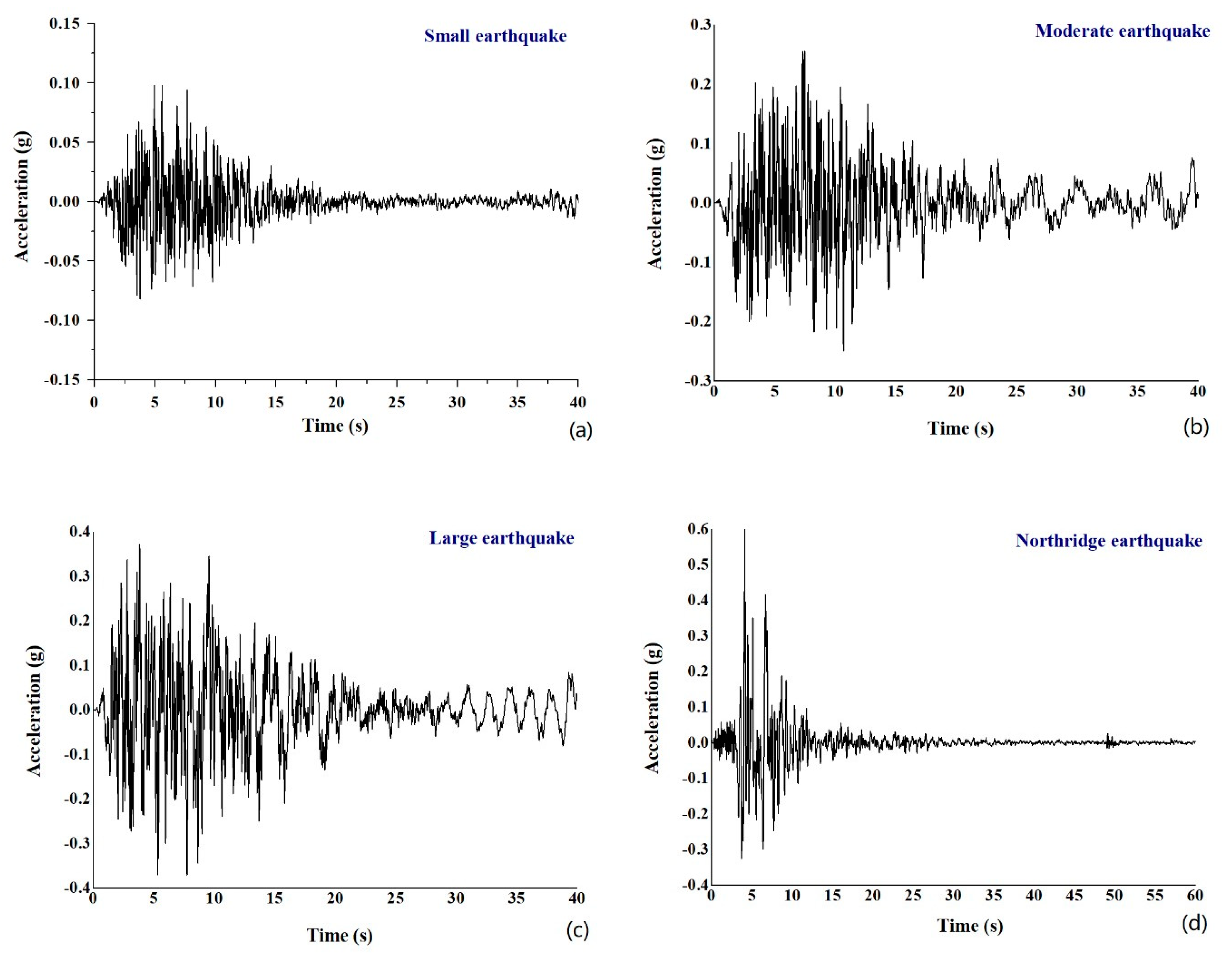
To investigate the relationship between the seismic responses of the bridge and the seismic intensity, as well as the seismic method of pounding damage, the intensity of earthquakes used in this paper increases stepwise; earthquakes with an exceeding probability of 63.2%, 10%, and 2% in 100 years (small, moderate, and large earthquakes) and the Northridge earthquake in the United States are considered [26].
Figure 5 show the time histories of the small, moderate, large, and the Northridge earthquakes. The peak acceleration of the earthquakes shows an increasing trend of 0.07 g, 0.26 g, 0.37 g, and 0.60 g.

4. Model Validation

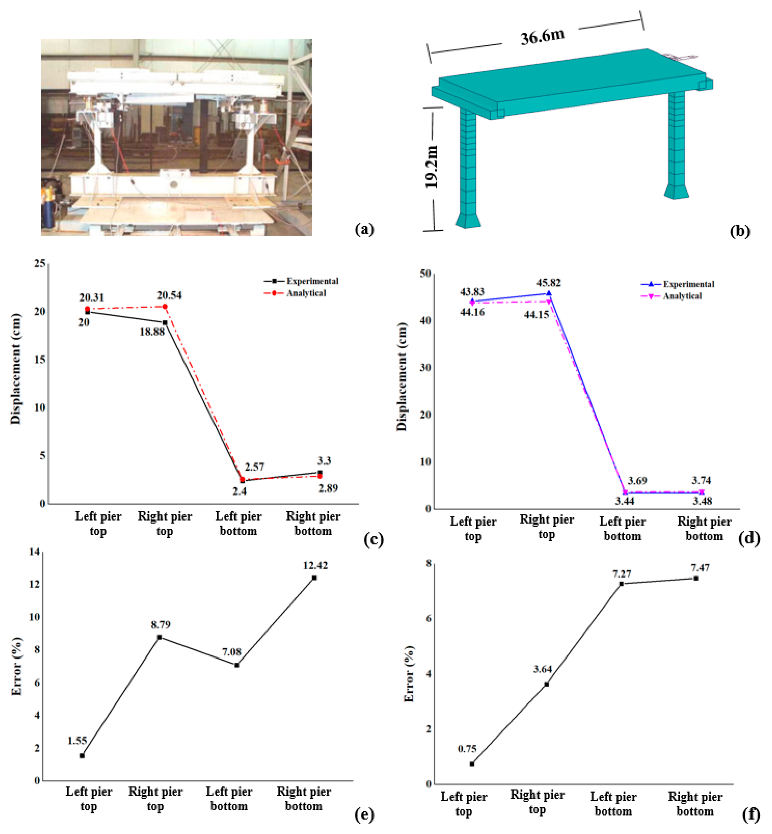
The model and algorithm for numerical simulation affect the final simulation results [38,40]. Different researchers verify the accuracy of the mathematical model and algorithm used in the numerical simulation by the existing shaking table test [41,42]. In this paper, we proved the correctness of the algorithm and mathematical model by a numerical simulation of Sahasrabudhe’s experiment [43,44]. In the shaking table test in the reference, a single-span bridge model at a 1:20 scale was designed, and was built as shown in Figure 6a; the weight of the deck was 12.36 kN and that of each pier was 0.53 kN. The bridge had a clear span of 1.83 m, a width of 0.89 m, and a height of 0.96 m. The deck of the bridge model was restrained from sliding by means of an angle welded between the deck and pier caps, and the bridge model was instrumented with stress transducer and accelerometers at both the piers and the deck to measure the displacement and acceleration response. The bridge was designed to have a natural period of 0.45 s in the longitudinal direction. The size of the numerical simulation model is consistent with the calculation model in the literature, as shown in Figure 6b. It has a clear span of 36.6 m, a width 17.8 m, and a height 19.2 m; the weight of the deck is 4992 kN and the piers weigh 424 kN each, and the bridge has a natural period of 0.45 s. The El Centro S00E earthquake with a peak acceleration of 0.87 g and the Northridge earthquake with a peak acceleration 1.75 g have been used to analyze the seismic response of the bridge. The analysis results show that, whether under the action of the El Centro wave or Northridge wave, the trend of the pier displacement analysis is consistent with the experimental results, as can be seen in Figure 6c,d.
It can be seen from Figure 6c,d that the two piers had a similar displacement response under the action of El Centro and Northridge earthquakes, but the numerical simulation analysis results deviate from the test results to some extent. Figure 6e,f show the error analysis of the test results and numerical analysis results. The calculation formula for error analysis is as follows:
δ = / L × 100 % ,
where δ is the actual relative error, %; is the absolute error, and L is the actual value.
The errors between the numerical analysis results and model test results are almost within 10%. The displacement value of the top of the left pier in Northridge earthquake is the closest to the test result, with a minimum error of 0.75%, while the displacement of the bottom of the right pier is quite different from the test result, with a maximum error of 12.42%. The main reason for this is that (1) there are errors between the measured values and actual values [45,46]; and, (2) like most researchers, we assumed the consolidation form of the structure foundation in this paper, leading to a difference in the analysis result between the actual test model and numerical model and thereby a difference between the calculation result and the experimental result. However, this error is small enough to meet the requirements for precision in this study [47,48,49].

5. Calculation Analysis and Discussion

5.1. Displacement of Girders, Bearings, and Pier Top

The seismic performances of more than 10,000 continuous girder bridges have been evaluated using a modal response spectrum analysis of a detailed finite-element model. The results indicate a considerable influence of the longitudinal ground motion component on the overall response [50]. Therefore, this paper mainly analyzes the longitudinal seismic response of bridge structures.
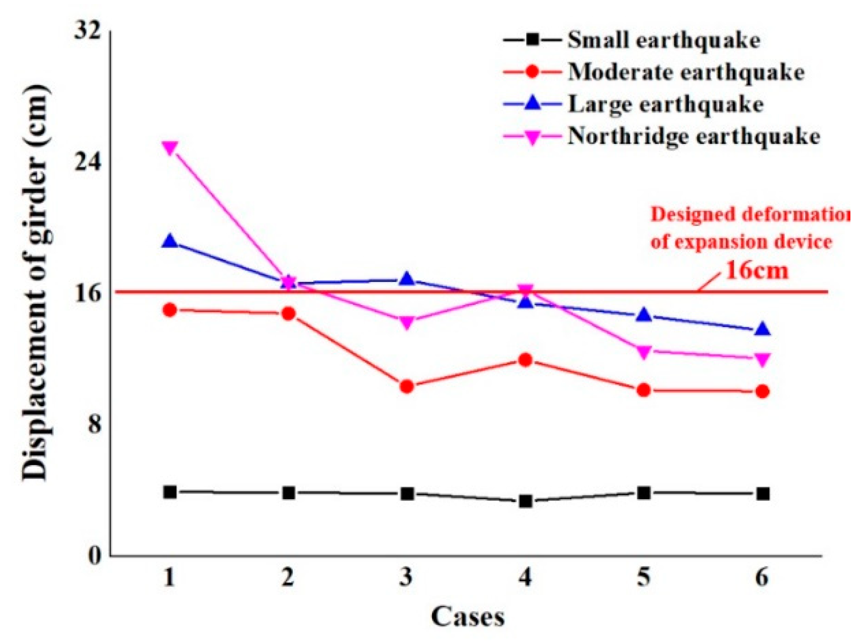
The longitudinal displacement of the girder of the bridge structure is the critical parameter to evaluate the seismic safety of the bridge. The excessive longitudinal displacement of the girder will cause seismic hazards, such as bridge pounding, unseating, etc. Different levels of seismic loads were applied to the bridge structures with six different cases for seismic measures (Figure 5). Figure 7 shows the displacement of the girder after different cases for seismic measures were used in earthquakes of different magnitudes. It can be seen in Figure 7 that, in different cases, with an increasing magnitude of the earthquake, the displacement of the girder increases, with significant changes in the Northridge earthquake. However, the displacement of the girder basically does not change under the action of a small earthquake in different cases. In Cases 1 and 2, the displacement of the girder end of the bridge structure exceeds the initial gap—16 cm—of the bridge expansion device under the action of large and Northridge earthquakes, leading to impact and damage at the expansion device. It was also found that the displacement of the girder is close to or more than 16 cm under the action of the large earthquake in Case 3 and the Northridge earthquake in Case 4. It should be noted that the displacement of the bridge girder under the action of the Northridge earthquake is less than or close to that under the action of the large earthquake in Cases 2 and 3, which is also observed in Cases 5 and 6. That may be due to the fact that the displacement of the bearing is not controlled by the unseating prevention devices until its displacement reaches its shear deformation in Case 4 without a restrainer, so the structure is subjected to a large earthquake impact force. The unseating prevention devices have a higher impact on the structural response under the action of a large earthquake than the Northridge earthquake. It is worth mentioning that the displacement of the bridge girder is less than 16 cm at earthquakes of different magnitudes in Cases 5 and 6. This means that the cooperation of the restrainer and unseating prevention devices can effectively avoid pounding and unseating damage. However, in Case 1, the largest displacements of the bridge girder without seismic measures are 14.99 cm, 19.12 cm, and 24.92 cm, respectively, under the action of moderate, large, and Northridge earthquakes, suggesting that the bridge girder can be protected to different extents only when seismic measures are taken.
The excessive deformation of the bearing in the bridge structure directly causes bearing failure and unseating damage. The displacement is an important index to evaluate the failure of the bearing. In this study, sliding rubber bearings were used for #1 and #5 piers of the bridge, while laminated rubber bearings were used for #2, #3, and #4 piers. Thus, the maximum displacement of the sliding rubber bearings and plate rubber bearings under the action of the earthquake was summarized as the control object.
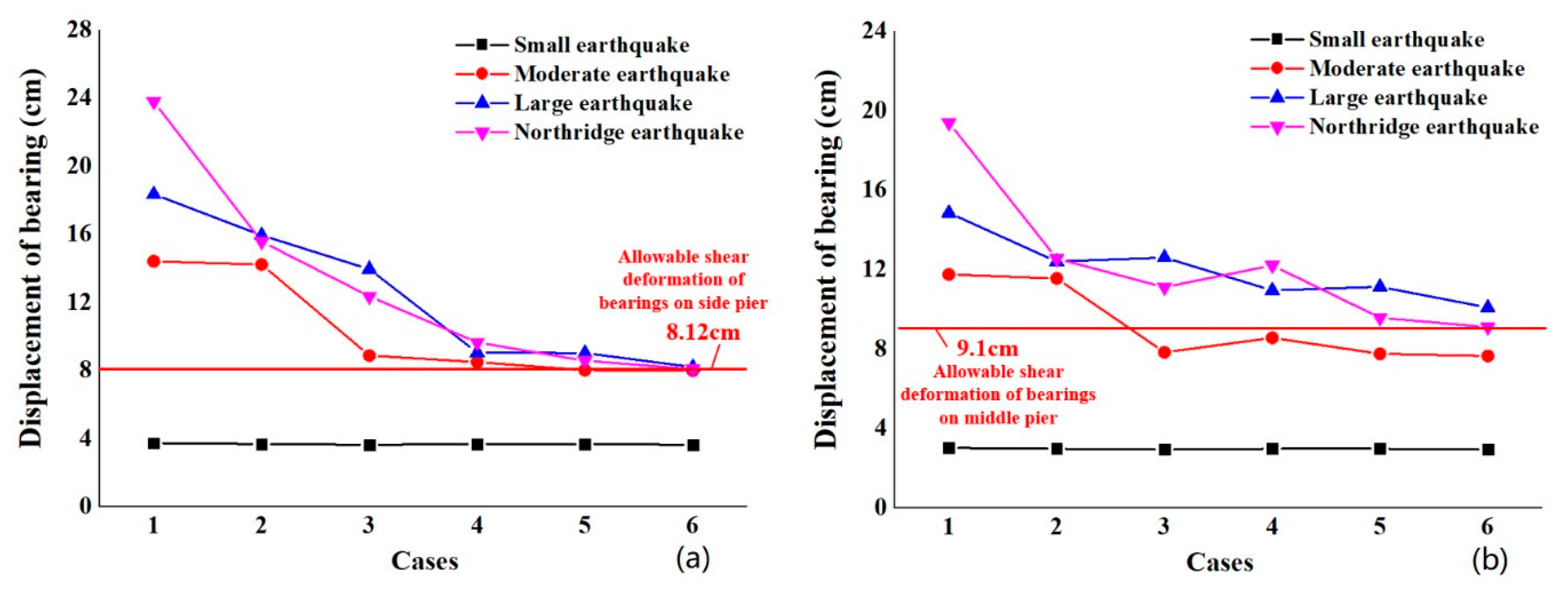
Figure 8 shows the change of the bearing displacement of the bridge structure with different seismic measures. In different cases, the displacement is much higher under the action of the Northridge and large earthquakes than moderate and small earthquakes, regardless of sliding rubber bearings (Figure 8a) or laminated rubber bearings (Figure 8b). Laminated rubber bearings have a similar displacement, of about 4 cm, than sliding rubber bearings, but a smaller displacement change than sliding rubber bearings under the action of the small earthquake. For the sliding rubber bearings and laminated rubber bearings, their displacement exceeds their allowable shear deformation (8.12 cm and 9.1 cm, respectively) when the magnitude of the earthquake increases to a moderate earthquake. This indicates that the bearing is largely destroyed, and the girder may fall from the piers.
Figure 8a shows that, in different combinations of seismic measures, the displacement of sliding rubber bearings is greater than 8.12 cm, especially in Cases 1, 2 and 3, but there are slight changes in Cases 4, 5, and 6 under the action of moderate, large, and Northridge earthquakes. That is mainly due to the fact that, when the magnitude of the earthquake increases, the restrainer is unable to restrict the excessive displacement of the structure sufficiently, and the unseating prevention devices effectively control the relative displacement of the substructure and superstructure of the bridge under the action of the earthquake due to its relatively large rigidity. In Cases 3 and 5, the displacement of the bridge bearings is slightly larger under the action of the large earthquake than the Northridge earthquake, mainly due to the fact that the restrainer is damaged so much under the action of the large earthquake that it is impossible to control the displacement of the bearings.
Figure 8b shows that the maximum displacement of the laminated rubber bearings is 19.38 cm, which is smaller than that of the sliding rubber bearings (23.78 cm), under the action of the Northridge earthquake. That means that the displacement of the sliding rubber bearings is larger than that of laminated rubber bearings under the action of the same earthquake, and #1 and #5 piers with sliding rubber bearings bear fewer seismic loads and are safer than #2, #3, and #4 piers in the earthquake. In addition, in Cases 3, 5 and 6, the displacement of the laminated rubber bearings under the action of the large earthquake is greater than the Northridge earthquake for the same reason as that of the sliding rubber bearings.
Both Figure 8a,b show that, in the combinations of seismic measures in Case 5 or 6, both the sliding rubber bearings and laminated rubber bearings have small displacement, but this is only slightly larger than the allowable shear deformation under earthquakes of different magnitudes. This means that these two combinations of seismic measures can reduce the probability of the unseating from the bearing more significantly than other combinations of seismic measures.
The displacement reduction of sliding rubber bearing is larger than that of laminated rubber bearings. The displacement of the bearings decreases most under the action of the Northridge earthquake. When there is no seismic measure in Case 1, the displacement of the sliding rubber bearings is 23.78 cm. In Case 6, the displacement of the sliding rubber bearings is 8.57 cm—about 36% of the displacement of the sliding rubber bearings in Case 1. The displacement of the laminated rubber bearings decreases from 19.38 cm in Case 1 to 9.59 cm in Case 6 by about a half.
The simulation results indicate that the effectiveness of seismic measures significantly prevents potential pounding and unseating damage to bridges due to the interaction between adjacent bridge segments caused by impacts. The result confirms Raheem’s research result and shows the importance of setting up seismic measures to prevent bridge collision [14]. The restrainer can totally avoid pounding damage and substantially mitigates the relative displacement to avoid unseating damage; this conclusion is the same as that of Liu’s research on railway bridges [12]. Unseating prevention devices are effective in maintaining the integrity of a total bridge system, and they prevent an excessive relative displacement between decks and can even prevent a deck that is dislodged from its support from falling, which proved once again that the bridge structure should include measures to prevent falling [38,51]. It was found that combination of seismic measures has received considerable attention in terms of reducing damages as well as improving the serviceability of the bridge; although our study is different from the selection type of seismic measures in Shrestha and DesRoches’s study, the result is consistent [33,52].
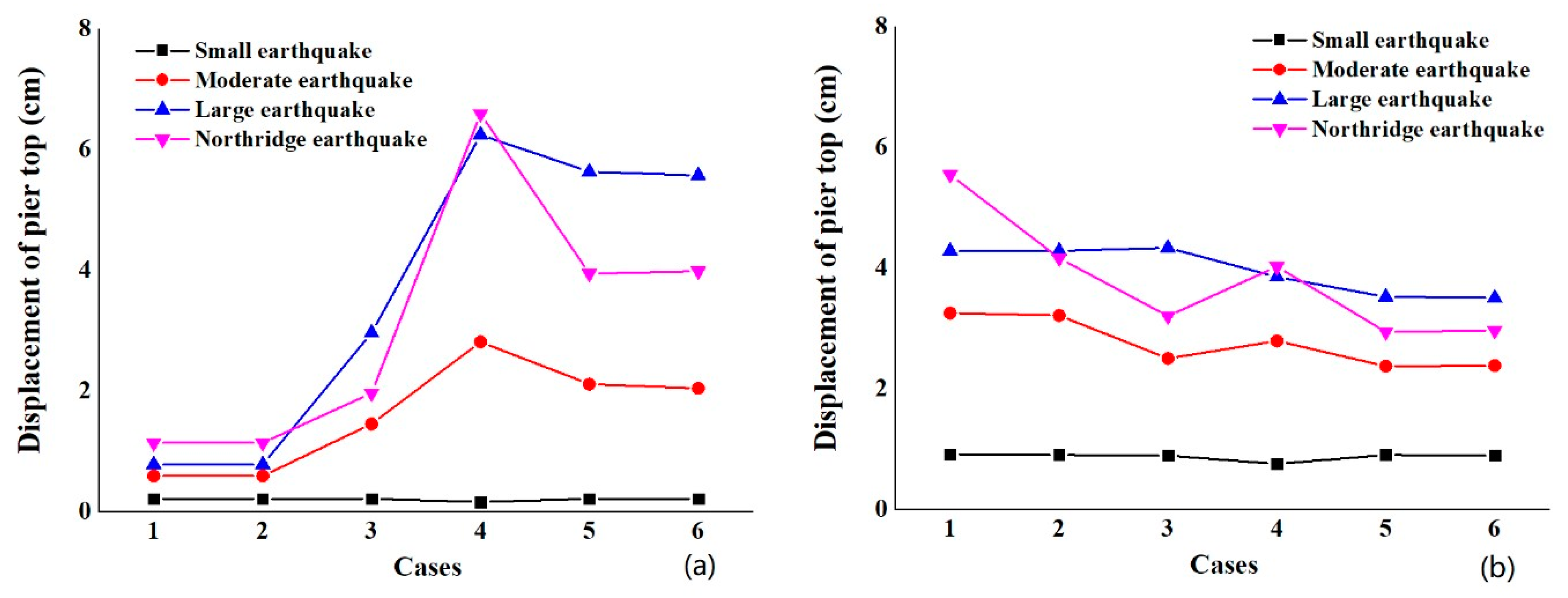
Figure 9 shows the change of the pier top displacement when different seismic measures are taken for the bridge under earthquakes of different magnitudes. In this part, #1 and #5 piers with sliding rubber bearings are compared with #2, #3, and #4 piers with laminated rubber bearings, and the maximum displacement of their respective tops is analyzed. Under the action of the small earthquake, the displacement of the pier top in different cases is relatively consistent, and #2, #3, and #4 piers have a greater maximum displacement of the pier top than #1 and #5 piers. The displacement of the pier top is much higher under the action of the Northridge and large earthquakes than small and moderate earthquakes.
Figure 9a shows that #1 and #2 piers have a smaller pier top displacement and close displacement under the action of different levels of earthquakes in Cases 1 and 2. The displacement difference is small under the action of moderate, large, and Northridge earthquakes, and the maximum displacement is 2.96 cm under the action of large earthquake in Case 3. Piers #1 and #5 have a larger pier top displacement in Case 4 than other cases under the action of moderate, large, and Northridge earthquakes—i.e., 2.81 cm, 6.24 cm and 6.59 cm—which increase to 4.76, 8 and 5.78 times the original design value, respectively. That is because, in the preliminary design, sliding rubber bearings are designed for #1 and #5 piers, while laminated rubber bearings are designed for #2, #3, and #4 piers. The sliding rubber bearings will slide under earthquake action so that a smaller seismic load is transmitted to #1 and #5 piers. When the restrainer and unseating prevention devices are installed, they increase the connection stiffness between the substructure and superstructure of #1 and #5 piers, distributing a bigger seismic load to the piers and thus increasing the pier top displacement of #1 and #5 piers. It is worth mentioning that the change of displacement is basically identical under earthquakes of different magnitudes in Cases 5 and 6 and much larger than Cases 1 and 2, meaning that the expansion device does not significantly control the bearing displacement. The expansion device and unseating prevention devices are used in Case 4, but the relative displacement between the girder and pier exceeded the allowable shear deformation of the bearing when the unseating prevention devices control the displacement, resulting in a larger impact force on the unseating prevention devices. Therefore, #1 and #5 piers have much higher pier top displacement in Case 4 than other Cases, and #2, #3, and #4 piers also have larger pier top displacement in Case 4 than Cases 3, 5, and 6.
Figure 9b shows that the pier top displacement of #2, #3, and #4 piers changes stably under earthquakes of different magnitudes in different cases. The pier top displacement of #2, #3, and #4 piers decreases when the restrainer and unseating prevention devices are added to the combination of seismic measures. In Cases 1, 2, and 3, the pier top displacement of #2, #3, and #4 piers is much higher than that of #1 and #5 piers under earthquakes of different magnitudes, which is mainly due to the fact that the low stiffness of the expansion device and restrainer leads to a small connection stiffness between the bridge girder and pier and thereby the transmission of less seismic load to the #1 and #5 piers than #2, #3, and #4 piers. In Cases 4, 5, and 6, #2, #3, and #4 piers have a smaller pier top displacement than #1 and #5 piers because of transmission of a bigger seismic load to #1 and #5 piers than #2, #3, and #4 piers due to the fact that the unseating prevention devices create a very stiff connection between the girder and pier. Piers #2, #3 and #4 have consistent pier top displacement and smaller pier top displacement in Cases 5 and 6 than other cases under earthquakes of different magnitudes, due to the fact that the restrainer and unseating prevention devices are used together.

5.2. Bending Moment

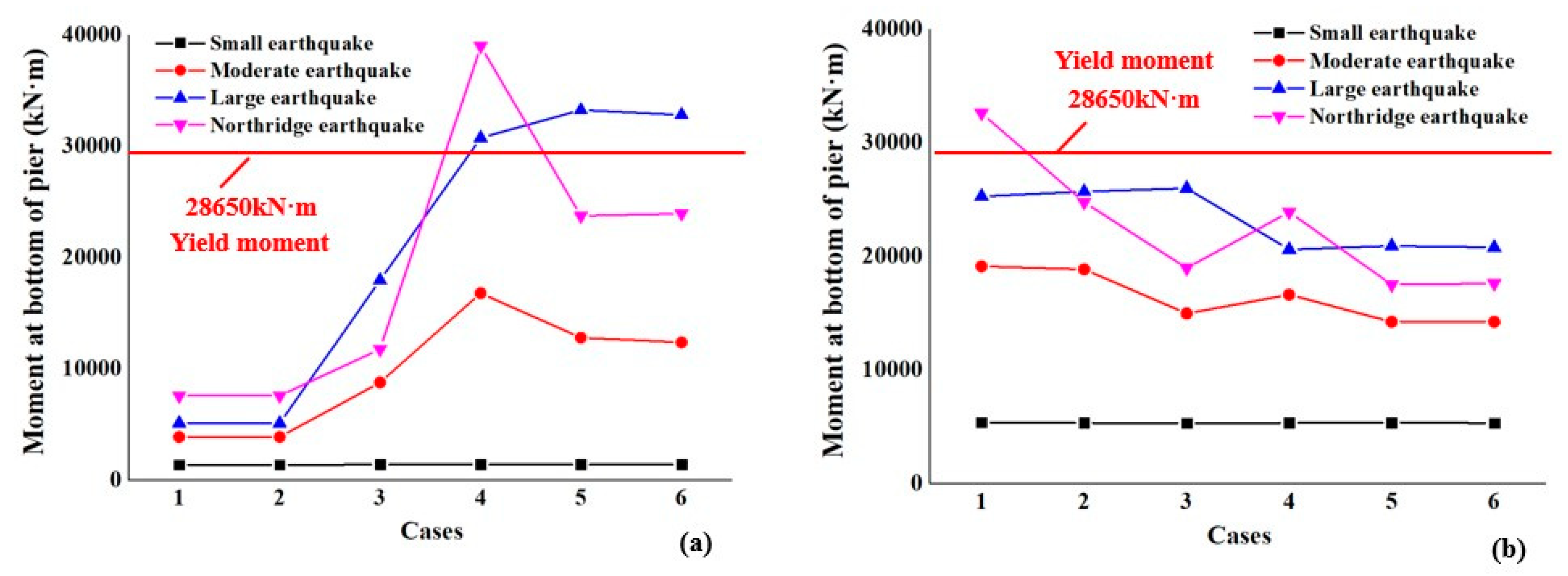
In an earthquake, the pier bears a large horizontal seismic force, leading to a large bending moment at the bottom of the pier. Once the bending moment exceeds the yield moment at the bottom of the pier, plastic failure of the pier will occur. Figure 10 shows the change of bending moment at the bottom of the pier after different combinations of seismic measures are used for the bridge structure under the action of earthquakes. The piers have the same height, so the bending moment at the bottom of each pier has a linear relationship with the pier top displacement; i.e., the bending moment at the bottom of each pier changes in the same manner as the pier top displacement. Under the action of the Northridge earthquake, the bending moment at the bottoms of the piers is the biggest in Case 1; in particular, that of #1 and #5 piers is 7564 kN·m, and that of #2, #3, and #4 piers is 32,594 kN·m.
The bending moment at the bottom of #1 and #5 piers does not change under the action of a small earthquake. Under the action of moderate, large, and Northridge earthquakes, the bending moment at the bottom of #1 and #5 piers increases compared with Cases 1 and 2, while the bending moment at the bottom of #2, #3, and #4 piers decreases. However, in Case 4, the displacement of the bearing has reached its allowable shear deformation when the unseating prevention devices control the bearing. Thus, the girder bears a relatively large impact force, and the unseating prevention devices have a bigger restraining force on the substructure and superstructure than the restrainer. That is why the bending moment at the bottom of #1 and #5 piers is greater in Case 4 than other cases.
In Figure 10a, Case 1 and Case 2 have small and basically identical bending moments under earthquakes of different magnitudes, indicating that the expansion device insignificantly influences the bending moments of #1 and #5 piers. Under earthquakes of different magnitudes, Case 3 has a slight bigger bending moment than Cases 1 and 2, but a much smaller bending moment than Cases 5 and 6. Case 4 has almost the biggest bending moment at the bottom of #1 and #5 piers in all the cases. Under the action of moderate, large, and Northridge earthquakes, the bending moment at the bottom of #1 and #5 piers is 16,775 kN·m, 30,729 kN·m, and 38,966 kN·m, respectively, which increase to 4.35, 6.02 and 5.15 times the original design value (7564 kN·m). In Cases 4, 5, and 6, the piers have a bigger bending moment at their bottom than their yield bending moment (28,650 kN·m) under the action of large and Northridge earthquakes, since the unseating prevention devices transfer less seismic load to #1 and #5 piers.
In Figure 10b, the #2, #3, and #4 piers have a bigger bending moment at their bottom in Case 1 than other cases; under the Northridge earthquake, the piers have a bending moment of 32,594 kN·m at their bottom, and this is bigger than the yield bending moment (28,650 kN·m). The bending moment at the bottom of #2, #3, and #4 piers decreases after seismic measures are taken. Under the action of moderate, large, and Northridge earthquakes, the #2, #3, and #4 piers have a bending moment at their bottom of 14,232 kN·m, 20,783 kN·m and 17,592 kN·m, respectively, which decreases to about 74%, 82%, and 54% of the initial design value (32,594 kN·m), all of which do not exceed their ultimate bending moment in Case 6.
The above analysis shows that the seismic measures increase the connection between the substructure and superstructure of the bridge, and primarily affect #1 and #5 piers with seismic measures. Thus, #1 and #5 piers with sliding rubber bearings bear a bigger seismic load, and the entire bridge gradually has an identical bending moment at the bottom of the piers.
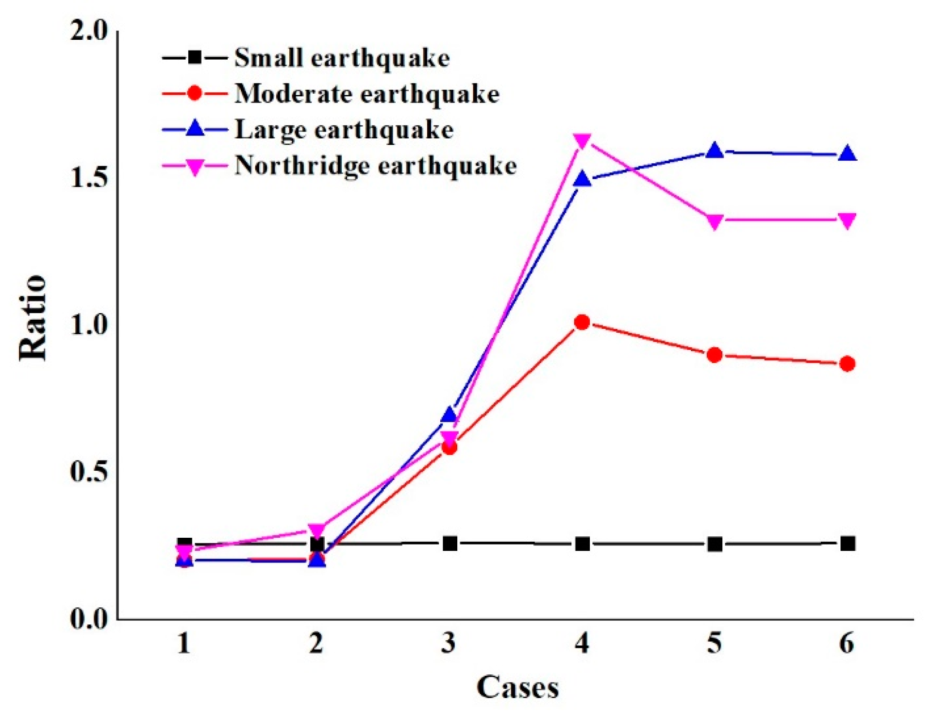
Figure 11 shows the ratio of bending moment at the bottom of #1 and #5 piers with sliding laminated rubber bearings to #2, #3, and #4 piers with laminated rubber bearings under the action of earthquakes. The seismic measure does not influence the bending moment at the bottom of the piers under the action of the small earthquake. However, the bending moment at the bottom of #1 and #5 piers is close to—but more than that of—#2, #3, and #4 piers, under the action of other earthquakes after seismic measures are taken. In Cases 1 and 2, the bending moment at the bottom of #1 and #5 piers is less than one-quarter of that of #2, #3, and #4 piers; in Cases 4, 5, and 6, the bending moment at the bottom of #1 and #5 piers is slightly more than that of #2, #3, and #4 piers under the action of large and Northridge earthquakes. That means that the unseating prevention devices dramatically strengthen the connection between the substructure and superstructure at #1 and #5 piers, so #1 and #5 share a bigger seismic load.
The above studies show that, although the seismic measures can increase the seismic performance of the bridge, they will also increase the ductility requirements of the piers for setting seismic measures. This is different from the results of other research, and the reason is that the structure in this paper is a continuous beam bridge, and the seismic response of its pier under an earthquake is quite different from that of the frame structure studied by Andrawes et al. [38], which is more susceptible to seismic measures.

5.3. Internal Force

5.3.1. Impact Force at Expansion Joints

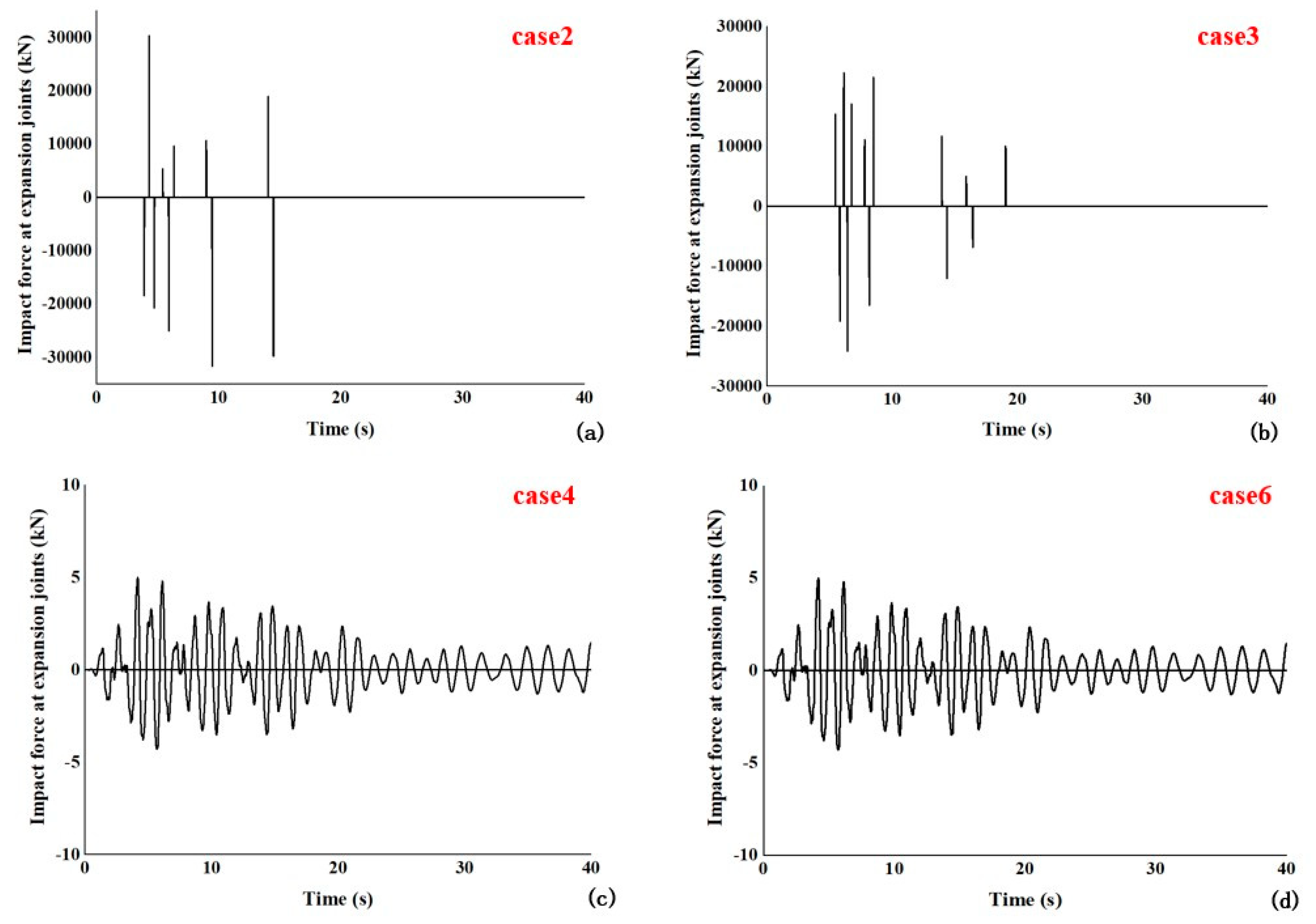
The pounding at bridge expansion joints under the action of the earthquake is an important control object in seismic design. Seismic measures greatly influence the impact force of expansion joints. Figure 12 shows the impact force acting on the expansion joint under the action of a large earthquake in different cases. Figure 12a shows the time history of the impact force at the expansion joint without seismic measures in Case 2. In the whole process of seismic excitation, the expansion device collides many times, with a maximum impact force of 30,301 kN.
Figure 12b shows that Case 3, in which the restrainer is installed, has a maximum impact force of 28,973 kN, which is smaller than Case 1. However, the expansion joint still collides due to the fact that the restrainer has a relatively limited restraining capacity. In Case 4, in which the unseating prevention devices are installed (see Figure 12c), and Case 6, in which the restrainer and unseating prevention devices are installed (as shown in Figure 12d), the impact forces at the expansion joints almost disappear, meaning that the seismic measures can effectively control the pounding between girders under the action of earthquakes.
The results showed that, under proper configurations, the seismic measures work effectively in reducing the actions of pounding in the longitudinal direction. The restrainers were effective through the entire recording and reduced the maximum hinge opening compared to Case 2. The result of this study is identical to that of Zhu and Andrawes [32,38].

5.3.2. Internal Force of Seismic Measures

In this paper, each seismic measure plays a vital role in restraining the excessive displacement of the structure and bears the seismic load in an earthquake. Table 3 shows the internal force peak value of seismic measures in each case under earthquakes of different magnitudes.
In Case 2, the expansion device has no large load, but only the rubber embedded in the expansion joint produces a small damping force under the action of small and moderate earthquakes. Under the action of large and Northridge earthquakes, the expansion device has a bigger internal force than its ultimate impact force of 15,000 kN.
In Case 3, the restrainer starts to bear the force under the action of the small earthquake; with increasing force, its internal force increases under the action of moderate and large earthquakes. The sliding rubber bearing has a smaller displacement, and the restrainer has a smaller internal force under the action of the Northridge earthquake than the large earthquake; the expansion device has the maximum internal force of 28,973 kN under the action of the large earthquake.
In Case 4, the expansion device hardly bears a force when the unseating prevention devices are installed [53]. The unseating prevention devices do not start under the action of the small earthquake. The internal force of the unseating prevention devices increases gradually under the action of moderate, large, and Northridge earthquakes. However, the maximum internal force (3691 kN) of the unseating prevention devices exceed its design breaking force, 3340 kN, under the action of the Northridge earthquake.
In Case 5, the function of the expansion device is not taken into account; the restrainer and the unseating prevention devices are applied together. The unseating prevention devices do not start under the action of the small earthquake, and the internal forces of the restrainer and unseating prevention devices increase under the action of moderate and large earthquakes. The internal forces of the restrainer and the unseating prevention devices are slightly smaller under the action of the Northridge earthquake than the large earthquake. The internal forces of the restrainer and the unseating prevention devices are smaller in Case 5 than Cases 3 and 4. For the restrainer under the action of the large earthquake, its internal force, 594 kN, can reduce to about half of its internal force, 1209 kN, without a coupling device. For the unseating prevention devices, their internal force is also much smaller than that when they are used alone and does not exceed its design breaking force. This means that the cooperation between the restrainer and unseating prevention devices is very beneficial to the forces on the two measures, reducing the internal force and playing a specific protective role under the action of an earthquake.
In Case 6, the expansion device, restrainer, and unseating prevention devices are applied together so that the expansion device does not collide, and the forces on other seismic measures are similar to those in Case 5. This shows that the expansion device only has a slight effect on the forces on the restrainer and unseating prevention devices [7].
In summary, both the restrainer and unseating prevention devices not only control the excessive displacement of the bridge structure under the action of the earthquake, but also cooperate in sharing the impact force caused by the earthquake load and make the forces on the structure and seismic measures more reasonable.

5.4. Energy Dissipation

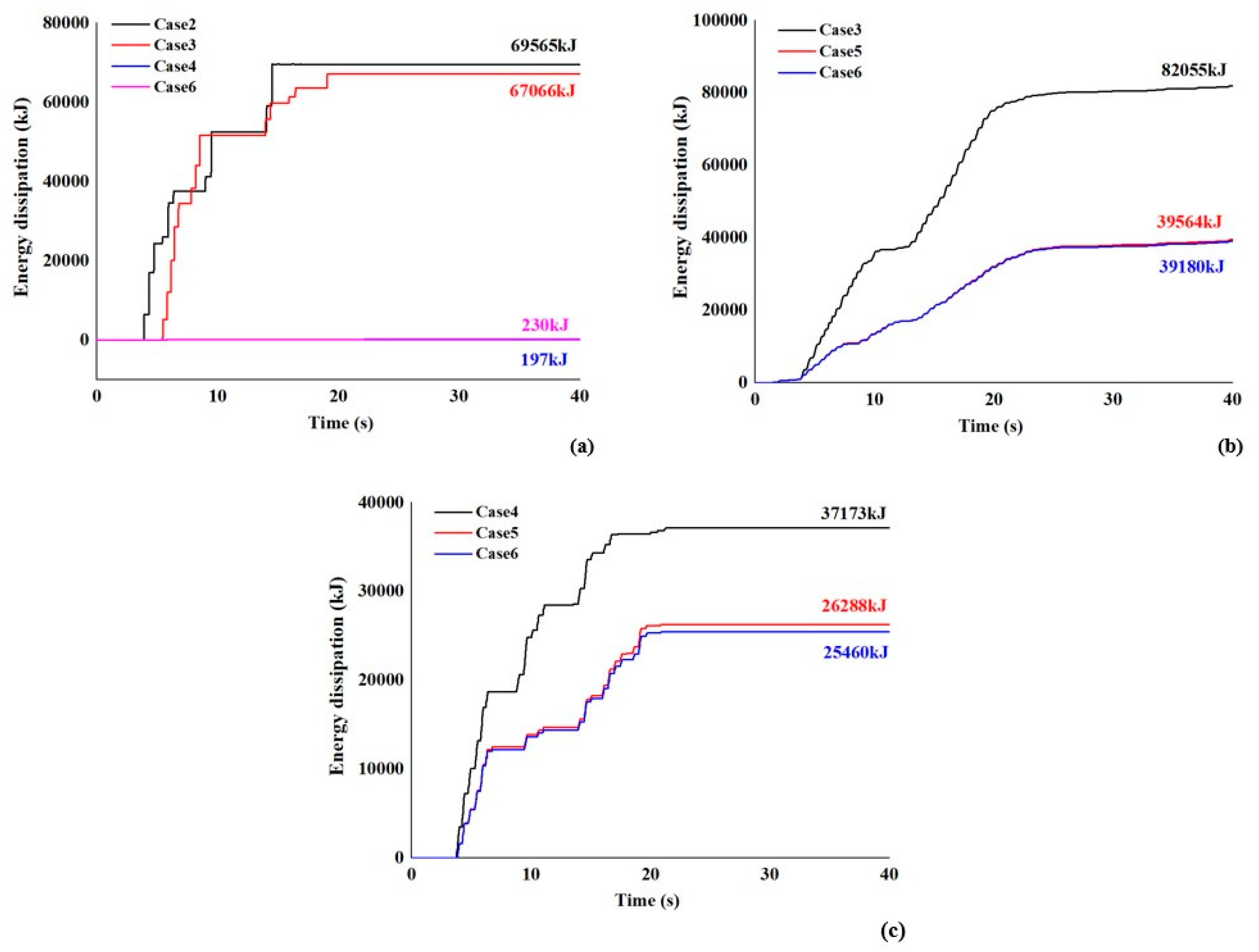
The expansion device, restrainer, and unseating prevention devices consume seismic energy during their deformation under the action of an earthquake. Figure 13 shows the cumulative dissipated energy of seismic measures in each case under the action of the large earthquake.
Figure 13a shows the cumulative dissipated energy of the expansion device in each case. In Cases 1, 3, 4, and 6, the expansion device has cumulative dissipated energies of 69,565 kJ, 67,066 kJ, 197 kJ, and 230 kJ, respectively. This indicates that the restrainer can reduce the impact force at the expansion joint to a certain extent, and the unseating prevention devices can completely control the displacement of the expansion device within 16 cm without pounding. Thus, the dissipated energy is smaller and is almost provided by the rubber material in the expansion device. The energy jump which occurs in the energy dissipation time history is the dissipated energy increment caused by the pounding at the expansion joint. When the pounding no longer occurs, and the dissipated energy of the expansion device no longer accumulates, the total consumed energy reaches a plateau.
Figure 13b shows the dissipated energy of the restrainer in each case. In Cases 3, 5, and 6, the restrainer deforms and dissipates energy progressively, with ultimate cumulative dissipated energies of 82,055 kJ, 39,564 kJ, and 39,180 kJ, respectively. This shows that the installed restrainer can better restrain the displacement and dissipate energy under the action of an earthquake. The restrainer dissipates a smaller energy in Cases 5 and 6, in which the restrainer and unseating prevention devices work together than Case 3, in which unseating prevention devices are not used.
Figure 13c shows the dissipated energy of the unseating prevention devices in each case. With reciprocating motion in an earthquake, the unseating prevention devices bear a large impact force several times while they considerably deform. In Cases 4, 5, and 6, the unseating prevention devices continuously deform and dissipate energy, with ultimate cumulative dissipated energies of 37,173 kJ, 26,828 kJ, and 25,460 kJ, respectively. The dissipated energy and the force on the unseating prevention devices are reduced to a certain extent in Case 5, in which the restrainer is used, and the expansion device is used in Case 6, meaning that multiple seismic measures share the seismic load and thereby reduce the seismic load on each device.
In summary, the joint application of the expansion device, restrainer, and unseating prevention devices effectively controls the excessive displacement of the bridge structure under the action of the earthquakes. Meanwhile, they cooperate with one another to share the impact force caused by the earthquake load and make the forces on the structure and seismic measures more reasonable. The multiple seismic measures show a much better seismic effect than a single seismic measure.
Therefore, Case 6 is the best in all cases. Table 4 shows the seismic response of the structure at all magnitudes of earthquakes and the ratios of the seismic response to the initial design value in Case 6.
Regarding the analysis of the seismic response of the structure at all magnitudes of earthquakes and the ratio of seismic response in Case 6 to Case 1 in Table 4, it can be seen that the displacements of the bridge girder and bearing generally decrease after the seismic measures are taken in each case. The displacement of the girder in Case 6 can be reduced to at most 48% of that in Case 1. The maximum displacement of the girder is 13.75 cm, which is smaller than the allowable deformation—16 cm—of the expansion joint at the girder end. The displacement of the bearing can be reduced to at most 34% of that in Case 1. For the laminated rubber bearing, its maximum displacement—10.07 cm—is slightly higher than its allowable shear deformation—9.1 cm—under the action of the large earthquake. Piers #1 and #5 have increasing displacement at their tops and an increasing bending moment at their bottoms, while #2, #3, and #4 piers have decreasing displacement at their tops and a decreasing bending moment at their bottoms. However, all the piers have a similar seismic response after seismic measures are taken. Under the action of the large earthquake, the maximum displacement of the pier tops is 5.57 cm, which is 7.14 times larger than that in Case 1, but the displacement of the pier tops does not exceed the allowable displacement of the piers. The maximum bending moment at the bottom of the piers is 32,803 kN·m, which is 6.43 times larger than that in Case 1, and slightly more than the ultimate bending moment of the piers. This means that the seismic measures can effectively restrain the relative displacement of the substructure and superstructure of the bridge and reduce the probability of the pounding, unseating and failure damages of the bridge structure under the action of an earthquake. Meanwhile, the seismic measures can dissipate the seismic energy, increase the overall stiffness of the bridge structure, and uniformly distribute the seismic load on the piers.

6. Conclusions

In this paper, the dynamic time history analysis of a four-span continuous girder bridge is carried out for earthquakes of different magnitudes. The large displacement of bridge bearings and expansion joints under the action of a large earthquake leads to seismic hazards, such as unseating, pounding, and collapse, so seismic measures were proposed to improve the seismic performance of the bridge in this paper. The restrainer and unseating prevention devices have different displacement control ranges, and the seismic effect of the expansion device should not be ignored. Thus, six different combinations of seismic measures were taken for the bridge in order to discuss the mechanical behaviors of the bridge structure, including the seismic performance structural displacement, the bending moment of piers, etc., and we comparatively analyzed the seismic effect of several combinations of seismic measures in this study. The following are the main conclusions of this study:
(1)
Under larger earthquakes, the initial design of the bridge (Case 1) was found to be damaged by bearing failure, pounding, expansion device failure, and collapse damages without the prevention of seismic measures. For the expansion joint, its maximum displacement—24.92—was much more than its design displacement—16 cm—under the action of the Northridge earthquake. The sliding rubber bearings and laminated rubber bearings have a maximum displacement of 23.78 cm and 19.38 cm, respectively, which are more than their shear deformation of 8.12 cm and 9.1 cm, respectively. The maximum bending moment, 32,594 kN·m, at their bottoms of #2, #3, and #4 piers with laminated rubber bearings is four times the maximum bending moment, 7564 kN·m, at the bottoms of #1 and #5 piers with sliding rubber bearings. The seismic load is unevenly distributed between the piers, leading to a great difference in displacement at the top of each pier.
(2)
Damping expansion devices can weaken the seismic response of the bridge slightly; restrainers can effectively reduce the displacement of the bridge and improve the overall stiffness of the bridge under small and moderate earthquakes. However, if the seismic magnitude exceeds a moderate earthquake, the restrainer cannot be effectively limited to the excessive displacements of the bridge. The combination of the restrainer and unseating prevention was found to be more effective at controlling the excessive displacement of the bridge. The expansion joint and bearing have a maximum displacement reduction of 48% and 34%, respectively. As the displacements of bearings and expansion joints were reduced within their allowable deformation, the bridge was prevented from pounding and collapse during earthquakes. In addition, the moment at the bottom and the displacement at the top of #1 and #5 piers greatly increased, and even slightly exceeded those of #2, #3, and #4 piers; however, all the piers have a similar seismic response, and the seismic load is uniformly distributed between the piers.
(3)
Under the action of the earthquake, a large displacement occurs to the sliding rubber bearings (#1 and #5 piers), so a smaller seismic load is transferred to #1 and #5 piers. Thus, #2, #3, and #4 piers have a bigger maximum displacement and bending moment than #1 and #5 piers. The restrainer and installed unseating prevention devices increase the connection stiffness between the substructure and superstructure of the bridge with #1 and #5 piers, distribute a bigger seismic load to the substructure, and increase the displacement at the top and bending moment at the bottom of #1 and #5 piers by a factor of more than four compared with the preliminary design. This revealed that seismic measures could increase the overall stiffness of the bridge and more evenly distribute the impact force and seismic energy among piers caused by earthquakes.
(4)
Under the action of the large and Northridge earthquakes, there is a big impact force at the expansion joint of the bridge. As no seismic measure is taken, the maximum impact force at the expansion joint is 30,301 kN, which is much more than the designed internal force, 15,000 kN, so the expansion joint is seriously damaged. After the restrainer is installed, the impact force at the expansion joint decreases to some extent, but the impact still exists at the expansion joint. When the restrainer and the unseating prevention devices are used together, the impact force at the expansion joint almost disappears. Seismic measures also bear a large internal force in an earthquake. When the restrainer or unseating prevention devices are used with expansion devices, the internal force is large, and the bridge may be damaged even under the action of the large earthquake. When the expansion device, the restrainer, and the unseating prevention devices are used together, the internal force of the restrainer and the unseating prevention devices are reduced to some extent. Several seismic measures can share the impact force caused by the earthquake load, dissipate the earthquake energy, improve the seismic performance of the structure and seismic measures, and make the force on the structure more reasonable.

Author Contributions

Y.Z. proposed the main framework of the paper. Y.Z. and D.L. mainly wrote the paper. Y.Z. and Y.S. revised the paper. All authors have read and agreed to the published version of the manuscript.

Funding

This research was funded by the National Natural Science Foundation of China (Grant No. 51808446,51908461) and the Natural Science Basic Research Plan in Shaanxi Province of China (Grant No. 2018JQ5184, 2018JQ5073, 2019SF-266, 2019JLM-54).

Conflicts of Interest

The authors declare no conflict of interest.

References

  1. Ruangrassamee, A.; Kawashima, K. Control of nonlinear bridge response with pounding effect by variable dampers. Eng. Struct. 2003, 25, 593–606. [Google Scholar] [CrossRef]
  2. Schanack, F.; Valdebenito, G.; Alvial, J. Seismic damage to bridges during the 27 February 2010 magnitude 8.8 Chile earthquake. Earthq. Spectra 2012, 28, 301–315. [Google Scholar] [CrossRef]
  3. Di, S.L.; Da, P.F.; Guerrini, G.; CalviG, P.M.; Prota, C. Seismic performance of bridges during the 2016 Central Italy earthquakes. Bull. Earthq. Eng. 2019, 17, 5729–5761. [Google Scholar]
  4. Kawashima, K.; Takahashi, Y.; Hanbin, G.; Wu, Z.; Zhang, J. Reconnaissance report on damages of bridges in 2008 Wenchuan, China, earthquake. J. Earthq. Eng. 2009, 13, 965–996. [Google Scholar] [CrossRef]
  5. Jankowski, R.; Wilde, K.; Fujino, Y. Reduction of pounding effects in elevated bridges during earthquakes. Earthq. Eng. Struct. Dyn. 2015, 29, 195–212. [Google Scholar] [CrossRef]
  6. Selna, L.G.; Malvar, L.J.; Zelinski, R.J. Bridge retrofit testing, Hinge cable restrainers. J. Struct. Eng. 1989, 115, 920–934. [Google Scholar] [CrossRef]
  7. DesRoches, R.; Pfeifer, T.; Leon, R.T.; Lam, T. Full-scale tests of seismic cable restrainer retrofits for simply supported bridges. J. Bridge Eng. 2003, 8, 191–198. [Google Scholar] [CrossRef]
  8. Di Sarno, L.; Del Vecchio, C.; Maddaloni, G.; Prota, A. Shake table studies of an as-built RC bridge with smooth bars. Eng. Struct. 2017, 136, 355–368. [Google Scholar] [CrossRef]
  9. Kawashima, K.; Unjoh, S. The damage of highway bridges in the 1995 Hyogo-ken nanbu earthquake and its impact on Japanese seismic design. J. Earthq. Eng. 1997, 1, 505–541. [Google Scholar] [CrossRef]
  10. Goel, R.K.; Chopra, A.K. Role of shear keys in seismic behavior of bridges crossing fault-rupture zones. J. Bridge Eng. 2008, 13, 398–408. [Google Scholar] [CrossRef] [Green Version]
  11. Están, J.D.J.W.; Santa María, H.; Riddell, R.; Arrate, C. Influence of the use of external shear keys on the seismic behavior of Chilean highway bridges. Eng. Struct. 2017, 147, 613–624. [Google Scholar] [CrossRef]
  12. Liu, C.; Gao, R. Design method for steel restrainer bars on railway bridges subjected to spatially varying earthquakes. Eng. Struct. 2018, 159, 198–212. [Google Scholar] [CrossRef]
  13. Choi, E.; Park, J.; Yoon, S.-J.; Choi, D.-H.; Park, C. Comparison of seismic performance of three restrainers for multiple-span bridges using fragility analysis. Nonlinear Dyn. 2010, 61, 83–99. [Google Scholar] [CrossRef]
  14. Raheem, S.E.A. Pounding mitigation and unseating prevention at expansion joints of isolated multi-span bridges. Eng. Struct. 2009, 31, 2345–2356. [Google Scholar] [CrossRef]
  15. Alam, M.S.; Bhuiyan, M.A.R.; Billah, A.H.M.M. Seismic fragility assessment of SMA-bar restrained multi-span continuous highway bridge isolated by different laminated rubber bearings in medium to strong seismic risk zones. Bull. Earthq. Eng. 2012, 10, 1885–1909. [Google Scholar] [CrossRef]
  16. Zhu, S.; Qiu, C.X. Incremental dynamic analysis of highway bridges with novel shape memory alloy isolators. Adv. Struct. Eng. 2014, 17, 429–438. [Google Scholar] [CrossRef]
  17. Saiidi, M.; Randall, M.; Maragakis, E.; Isakovic, T. Seismic restrainer design methods for simply supported bridges. J. Bridge Eng. 2001, 6, 307–315. [Google Scholar] [CrossRef]
  18. DesRoches, R.; Fenves, G.L. Design of Seismic Cable Hinge Restrainers for Bridges. J. Struct. Eng. 2000, 126, 500–509. [Google Scholar] [CrossRef]
  19. DesRoches, R.; Fenves, G.L. Simplified restrainer design procedure for multiple-frame bridges. Earthq. Spectra 2001, 17, 551–567. [Google Scholar] [CrossRef]
  20. Vlassis, A.G.; Maragakis, E.; Saiidi, M. Experimental evaluation of longitudinal seismic performance of bridge restrainers at in-span hinges. J. Test. Eval. 2004, 32, 96–105. [Google Scholar] [CrossRef]
  21. Li, S.; Hedayati, D.F.; Wang, J.Q.; Alam, M.S. Displacement-Based Seismic Design of Steel, FRP, and SMA Cable Restrainers for Isolated Simply Supported Bridges. J. Bridge Eng. 2018, 23, 04018032. [Google Scholar] [CrossRef]
  22. Kawashima, K.; Watanabe, G. Effectiveness of cable-restrainer for mitigating rotation of a skewed bridge subjected to strong ground shaking. Doboku Gakkai Ronb. 2001, 675, 141–159. [Google Scholar] [CrossRef] [Green Version]
  23. Julian, F.D.R.; Hayashikawa, T.; Obata, T. Seismic performance of isolated curved steel viaducts equipped with deck unseating prevention cable restrainers. J. Constr. Steel Res. 2007, 63, 237–253. [Google Scholar] [CrossRef]
  24. Won, J.H.; Mha, H.S.; Cho, K.I.; Kim, S.-H. Effects of the restrainer upon bridge motions under seismic excitations. Eng. Struct. 2008, 30, 3532–3544. [Google Scholar] [CrossRef]
  25. Shrestha, B.; Hao, H.; Bi, K. Effectiveness of using rubber bumper and restrainer on mitigating pounding and unseating damage of bridge structures subjected to spatially varying ground motions. Eng. Struct. 2014, 79, 195–210. [Google Scholar] [CrossRef]
  26. Guo, J.J.; Zhong, J.; Dang, X.Z.; Yuan, W.C. Influence of Multidirectional Cable Restrainer on Seismic Fragility of a Curved Bridge. J. Bridge Eng. 2019, 24, 04019001. [Google Scholar] [CrossRef]
  27. Andrawes, B.; DesRoches, R. Comparison between shape memory alloy seismic restrainers and other bridge retrofit devices. J. Bridge Eng. 2007, 12, 700–709. [Google Scholar] [CrossRef]
  28. Ghosh, G.; Singh, Y.; Thakkar, S.K. Seismic response of a continuous bridge with bearing protection devices. Eng. Struct. 2011, 33, 1149–1156. [Google Scholar] [CrossRef]
  29. Kawashima, K.; Gaku, S. Effect of restrainers to mitigate pounding between adjacent decks subjected to a strong ground motion. In Proceedings of the 12th World Conference on Earthquake Engineering, Auckland, New Zealand, 30 January–4 February 2000. [Google Scholar]
  30. Polycarpou, P.C.; Komodromos, P. Numerical investigation of potential mitigation measures for poundings of seismically isolated buildings. Earthq. Struct. 2011, 2, 1–24. [Google Scholar] [CrossRef]
  31. Zhang, Y.M.; Qin, X.X. Research on Bridge Damage-Reduction Seismic Performance with Variable Parameter Cable-Unseating Prevention Devices. Appl. Mech. Mater. 2014, 638, 977–982. [Google Scholar] [CrossRef]
  32. Zhu, P.; Abe, M.; Fujino, Y. Evaluation of pounding countermeasures and serviceability of elevated bridges during seismic excitation using 3D modelling. Earthq. Eng. Struct. Dyn. 2004, 33, 591–609. [Google Scholar] [CrossRef]
  33. Shrestha, B.; Hao, H.; Bi, K. Devices for protecting bridge superstructure from pounding and unseating damages: An overview. Struct. Infrastruct. Eng. 2017, 13, 313–330. [Google Scholar] [CrossRef] [Green Version]
  34. Xiang, N.; Li, J. Seismic performance of highway bridges with different transverse unseating-prevention devices. J. Bridge Eng. 2016, 21, 04016045. [Google Scholar] [CrossRef]
  35. Zhang, Y.M.; Cui, Y.; Liu, J. Collapse-Prevention Design and Damage-Reduction Seismic Performance Analysis of Bridges. Appl. Mech. Mater. 2014, 640, 1997–2000. [Google Scholar] [CrossRef]
  36. Guan, Z.G.; Li, J.Z.; Xu, Y. Performance test of energy dissipation bearing and its application in seismic control of a long-span bridge. J. Bridge Eng. 2009, 15, 622–630. [Google Scholar] [CrossRef]
  37. Padgett, J.E.; Nielson, B.G.; DesRoches, R. Selection of optimal intensity measures in probabilistic seismic demand models of highway bridge portfolios. Earthq. Eng. Struct. Dyn. 2008, 37, 711–725. [Google Scholar] [CrossRef]
  38. Guo, A.; Li, Z.; Li, H.; Ou, J. Experimental and analytical study on pounding reduction of base-isolated highway bridges using MR dampers. Earthq. Eng. Struct. Dyn. 2009, 38, 1307–1333. [Google Scholar] [CrossRef]
  39. Andrawes, B.; Reginald, D. Unseating prevention for multiple frame bridges using superelastic devices. Smart Mater. Struct. 2005, 14, S60. [Google Scholar] [CrossRef]
  40. Wang, L.; Su, J.W.; Gu, Z.L.; Tang, L.Y. Numerical Study on Flow Field and Pollutant Dispersion in an Ideal Street Canyon within a Real Tree Model at Different Wind Velocities. Comput. Math. Appl. 2020. [Google Scholar] [CrossRef]
  41. Cheng, C.T. Shaking table tests of a self-centering designed bridge substructure. Eng. Struct. 2008, 30, 3426–3433. [Google Scholar] [CrossRef]
  42. Johnson, R.; Padgett, J.E.; Maragakis, M.E.; Desroches, R. Large scale testing of nitinol shape memory alloy devices for retrofitting of bridges. Smart Mater. Struct. 2008, 17, 035018. [Google Scholar] [CrossRef]
  43. Sahasrabudhe, S.; Nagarajaiah, S. Experimental study of sliding base-isolated buildings with magnetorheological dampers in near-fault earthquakes. J. Struct. Eng. 2005, 131, 1025–1034. [Google Scholar] [CrossRef] [Green Version]
  44. Sahasrabudhe, S.; Nagarajaiah, S. Semi-active control of sliding isolated bridges using MR dampers: An experimental and numerical study. Earthq. Eng. Struct. Dyn. 2010, 34, 965–983. [Google Scholar] [CrossRef]
  45. Xiang, N.; Alam, M.S.; Li, J. Shake table studies of a highway bridge model by allowing the sliding of laminated-rubber bearings with and without restraining devices. Eng. Struct. 2018, 171, 583–601. [Google Scholar] [CrossRef]
  46. Yi, J.; Yang, H.; Li, J. Experimental and numerical study on isolated simply-supported bridges subjected to a fault rupture. Soil Dyn. Earthq. Eng. 2019, 127, 105819. [Google Scholar] [CrossRef]
  47. Kim, Y.; Park, G. Nonlinear dynamic response structural optimization using equivalent static loads. Comput. Method Appl. Mech. Eng. 2010, 199, 660–676. [Google Scholar] [CrossRef]
  48. Wang, X.Y.; Zhu, B.; Cui, S. Research on collapse process of cable-stayed bridges under strong seismic excitations. Shock Vib. 2017, 2017, 7185281. [Google Scholar] [CrossRef] [Green Version]
  49. Jiang, X.; Kolstein, M.H.; Bijlaard, F.S.K. Experimental and numerical study on mechanical behavior of an adhesively-bonded joint of FRP–steel composite bridge under shear loading. Compos. Struct. 2014, 108, 387–399. [Google Scholar] [CrossRef]
  50. Lee, T.Y.; Hung, W.H.; Chung, K.J. Seismic-induced collapse simulation of bridges using simple implicit dynamic analysis. Eng. Struct. 2018, 177, 1–11. [Google Scholar] [CrossRef]
  51. Xiang, N.; Goto, Y.; Obata, M.; ShahriaAlam, M. Passive seismic unseating prevention strategies implemented in highway bridges: A state-of-the-art review. Eng. Struct. 2019, 197, 77–93. [Google Scholar] [CrossRef]
  52. DesRoches, R.; Muthukumar, S. Effect of pounding and restrainers on seismic response of multiple-frame bridges. J. Struct. Eng. 2002, 128, 860–869. [Google Scholar] [CrossRef]
  53. Chouw, N.; Hao, H. Seismic design of bridge structures with allowance for large relative girder movements to avoid pounding. Bull. N. Z. Soc. Earthq. Eng. 2009, 42, 75–85. [Google Scholar] [CrossRef]
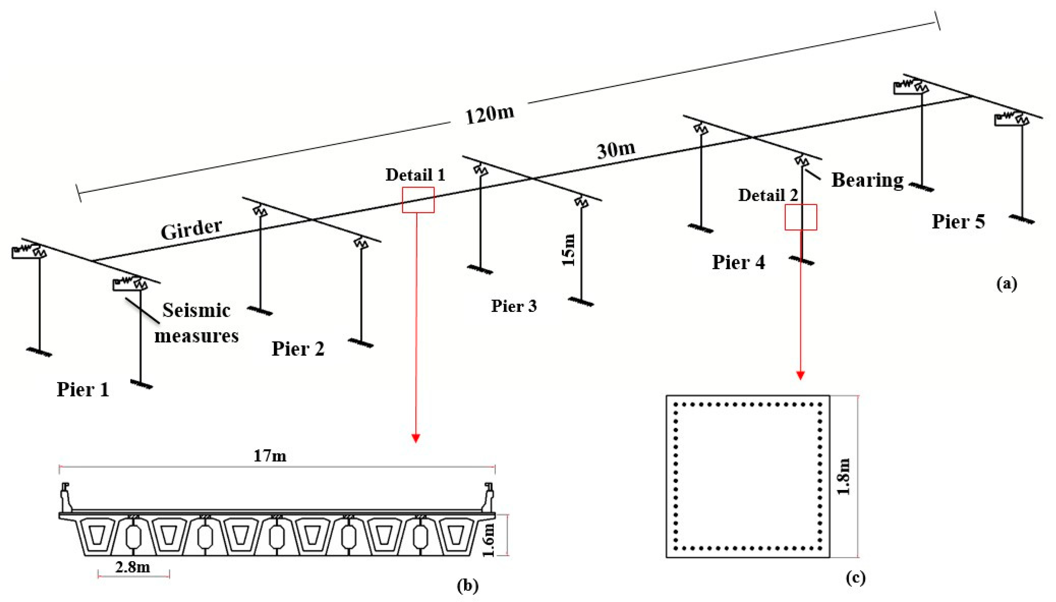
Figure 1. Finite-element model of bridge: (a) detail of bridge; (b) section of girder; (c) section of pier.
Applsci 10 00624 g001
Figure 2. Finite element model of expansion devices.
Applsci 10 00624 g002
Figure 3. Structural diagram and finite element model of restrainer: (a) structural diagram; (b) finite element model.
Applsci 10 00624 g003
Figure 4. Different forms of cable unseating prevention devices and finite element model: (a) girder-to-girder form, (b) pier-to-girder form, (c) finite element model of cable unseating prevention devices.
Applsci 10 00624 g004
Figure 5. Time history of earthquakes: (a) small earthquake, (b) moderate earthquake, (c) large earthquake, and (d) Northridge earthquake.
Applsci 10 00624 g005
Figure 6. Models and results: (a) experimental model, (b) analytical model, (c) seismic response under El Centro earthquake, (d) seismic response under Northridge earthquake, (e) error analysis of the test and numerical simulation (El Centro earthquake), and (f) error analysis of the test and numerical simulation (Northridge earthquake).
Applsci 10 00624 g006
Figure 7. Displacement of girders in different cases under different earthquakes.
Applsci 10 00624 g007
Figure 8. Displacement of bearings in different cases under different earthquakes: (a) piers #1 and #5 and (b) piers #2, #3, and #4.
Applsci 10 00624 g008
Figure 9. Displacement of the pier top in different cases under different earthquakes: (a) side piers and (b) middle piers.
Applsci 10 00624 g009
Figure 10. Moment of the pier bottom in different cases under different earthquakes: (a) side piers and (b) middle piers.
Applsci 10 00624 g010
Figure 11. Moment ratio at pier bottom.
Applsci 10 00624 g011
Figure 12. Impact force at expansion joints under a large earthquake: (a) Case 2, (b) Case 3, (c) Case 4, and (d) Case 6.
Applsci 10 00624 g012
Figure 13. Cumulative energy dissipation of seismic measure: (a) energy dissipation of expansion devices, (b) energy dissipation of the restrainer, (c) energy dissipation of the unseating prevention device.
Applsci 10 00624 g013
Table 1. Design parameters of bearings.
Parameters of BearingsSlide Rubber BearingsLaminated Rubber Bearings
Plane size of bearings (mm)400 × 450400 × 450
Maximum bearing pressure/(kN)17163481
Height of bearings (mm)116130
Total thickness of rubber layer (mm)8295
Longitudinal displacement of bearing without braking force (mm)/45
Maximum longitudinal displacement of bearing considering braking force (mm)9063
Allowable shear deformation (mm)81.291
Table 2. Case settings.
Primary Design BridgeExpansion DeviceRestrainerUnseating Prevention Device
Case 1YesNoNoNo
Case 2YesYesNoNo
Case 3YesYesYesNo
Case 4YesYesNoYes
Case 5YesNoYesYes
Case 6YesYesYesYes
Table 3. Maximum internal force of seismic measures under different earthquakes.
Seismic MeasuresSmall EarthquakeModerate EarthquakeLarge EarthquakeNorthridge Earthquake
Case 2Expansion devices1330,30129,973
Case 3Expansion devices1328,9734
Restrainer495821209941
Case 4Expansion devices1355
Unseating prevention device0181432133691
Case 5Restrainer52511594544
Unseating prevention device070325871461
Case 6Expansion devices1353
Restrainer49509593 548
Unseating prevention device06672589 1556
Table 4. Seismic responses of bridge under different earthquakes.
EarthquakesPositionsDisplacement of Girder (cm)Case6/Case1 (%)Displacement of Pier Top (cm)Case6/Case1 (%)Bearing DisplacEment (cm)Case 6/Case 1 (%)Bending Moment of Pier Bottom (kN·m)Case 6/Case 1 (%)
Small EarthquakeSide pier3.830.98 0.211.00 3.620.98 13771.00
middle pier3.830.98 0.890.98 2.930.97 52980.99
Moderate EarthquakeSide pier10.030.67 2.043.46 7.970.55 12,3633.20
middle pier10.030.67 2.380.73 7.640.65 14,2320.74
Large EarthquakeSide pier13.750.72 5.577.14 8.180.45 32,8036.43
middle pier13.570.71 3.50.82 10.070.68 20,7830.82
Northridge EarthquakeSide pier12.050.48 3.983.49 8.070.34 23,9243.16
middle pier12.050.48 2.960.53 9.090.47 17,5920.54