Article

Multimode Guided Wave Detection for Various Composite Damage Types

Department of Mechanical Engineering, University of South Carolina, 300 Main Street, Columbia, SC 29208, USA
*
Author to whom correspondence should be addressed.
Appl. Sci. 2020, 10(2), 484; https://doi.org/10.3390/app10020484
Submission received: 13 December 2019 / Revised: 2 January 2020 / Accepted: 7 January 2020 / Published: 9 January 2020
(This article belongs to the Special Issue Guided Wave-Based Damage Identification for Composite Structures)

Abstract

:
This paper presents a new methodology for detecting various types of composite damage, such as delamination and impact damage, through the application of multimode guided waves. The basic idea is that various wave modes have different interactions with various types of composite damage. Using this method, selective excitations of pure-mode guided waves were achieved using adjustable angle beam transducers (ABTs). The tuning angles of various wave modes were calculated using Snell’s law applied to the theoretical dispersion curves of composite plates. Pitch–catch experiments were conducted on a 2-mm quasi-isotropic carbon fiber-reinforced polymer (CFRP) composite plate to validate the excitations of pure fundamental symmetric mode (S0) and shear horizontal mode (SH0). The generated pure S0 mode and SH0 mode were used to detect and separate the simulated delamination and actual impact damage. It was observed that S0 mode was only sensitive to the impact damage, while SH0 mode was sensitive to both simulated delamination and impact damage. The use of pure S0 and SH0 modes allowed for damage separation. In addition, the proposed method was applied to a 3-mm-thick quasi-isotropic CFRP composite plate using multimode guided wave detection to distinguish between delamination and impact damage. The experimental results demonstrated that the proposed method has a good capability to detect and separate various damage types in composite structures.

1. Introduction

Composite materials have been widely used in aerospace structures due to their advantages of having high specific strength and stiffness, having design flexibility, and being lightweight [1]. However, composite structures are prone to various types of damage, including debonding, delamination, and impact damage. The detection and characterization of various types of composite damage are quite difficult. Delamination is a common and dangerous failure mode for composite structures, because it occurs and grows in the absence of any visible surface damage, making it difficult to detect through visual inspection [2]. In addition, barely visible impact damage (BVID) due to low-velocity impact, in the form of fiber breakage, matrix cracking, and interlaminar delamination, is also invisible to the naked eye and is easily induced from various sources such as bird strikes, tools dropped on parts, or runway debris [3,4]. BVID can result in a noticeable decrease in the load-carrying capability of the composite structures, and such damage can develop progressively, leading to a catastrophic failure. Due to general anisotropic behavior [5] and complex damage scenarios, the successful implementation of damage detection in composite structures is always challenging.
Various nondestructive testing (NDT) techniques have been developed for damage detection in composite structures, including thermography [6], eddy currents [7], and ultrasonic C-scans [8]. However, these conventional NDT methods are often expensive, time-consuming, and labor-intensive, and they depend heavily on the skill and experience of the operator. Structural health monitoring (SHM) technologies offer a promising alternative for damage detection in composite structures. In recent decades, many SHM techniques have been developed for damage detection, such as acoustic emissions (AEs) [9], electromechanical impedance (EMI) [10], and guided wave-based methods [11,12,13,14,15,16,17,18]. Among them, guided wave-based SHM technologies have been used to detect various damage types in composite structures, including delamination [12,13], debonding [14], and impact damage [15,16,17,18].
Guided waves have the advantage of long-distance propagation in complex structures and low energy loss, and they have been widely used in the structural health monitoring of composite structures. However, the problem for a typical guided wave is complicated by the existence of at least two wave modes at any given frequency and by the inherent dispersive nature of the guided wave modes that exist in thin-wall structures, which make the results difficult to interpret. To solve the problem, researchers have been using the tuning effect to find the gist of a suitable frequency that can excite a single-mode guided wave [19]. A technique involving double piezoelectric transducers with symmetric bonding has also been tried for the selective excitation of a single-mode wave [20]. In recent years, an angle beam transducer (ABT) with a wedge has also been utilized to achieve pure-mode guided wave excitation based on Snell’s law [21,22,23]. Quaegebeur et al. [21] used an ABT pair, one transmitter and one receiver, to detect the disbond in composite bonded joints using fundamental symmetric mode (S0) at 300 kHz. The ABT pair has also been utilized to detect the delamination simulated by a Teflon insert in a crossply composite plate, with the pure S0 mode being used [22]. Toyama and Takatsubo [23] used an ABT and an acoustic emission (AE) transducer to detect impact damage in a crossply composite plate using S0 mode. These studies have facilitated our understanding of guided wave-based SHM applications using ABTs.
Compared to the widely used S0 mode, the fundamental shear horizontal (SH0) wave is relatively simple, but has been investigated less often, probably due to the traditional notion that SH waves are usually excited by electromagnetic acoustic transducers (EMATs) [24]. However, EMAT methods are not appropriate for composites. It is well known that SH0 mode is more sensitive to delamination in composites [25]. The significance of SH waves has increased in recent years due to the development of new techniques to overcome difficulties associated with SH wave generation. SH wave piezoelectric transducers based on d24, d36, d35, and d15 piezoelectric wafers or strips have been developed for the generation of SH waves [26,27]. However, these SH wave transducers have to be permanently bonded onto a structure to be effective. The pure-mode SH0 wave excitation and its NDT applications for composites are very limited.
In this paper, a new methodology is presented to detect and separate various composite damage types based on multiple pure-mode guided waves generated by an adjustable ABT pair. The idea is that various wave modes interact differently with various types of composite damage. First, the tuning angles of various wave modes were obtained based on Snell’s law applied to the guided-wave dispersion curves of composite plates. Then, pitch–catch experiments using an adjustable ABT pair were conducted to validate the excitations of pure S0 mode and SH0 mode in a 2-mm quasi-isotropic carbon fiber-reinforced polymer (CFRP) composite plate. Although an ABT excitation consists of pressure waves, the generation of SH0 was possible due to the anisotropy of the quasi-isotropic composite layup [28]. Next, experiments were conducted on the 2-mm quasi-isotropic composite plate to detect and separate the delamination simulated by a Teflon insert and the actual impact damage due to low-velocity impact. Finally, the proposed technique was applied to a 3-mm quasi-isotropic CFRP composite plate using multimode guided wave detection to distinguish between delamination and impact damage. The experimental results demonstrate that the proposed method has a good capability to detect and separate various damage types in composite structures.

2. The Theory of Angle Beam Transducers for Single-Mode Excitation

Angle beam transducers (ABTs) and wedges are generally used to excite and receive single-mode guided waves. Let cw be the velocity of the pressure waves in the wedge, c be the phase velocity of the desired wave mode at a selected frequency in a composite laminate, and θ be the incident angle of the pressure waves impinging on the structure (also called the tuning angle), as shown in Figure 1. According to Snell’s law, a wave mode with a phase velocity of c will be enhanced through phase matching [29], much more so than waves of any other phase velocity, if the following condition is satisfied:
s i n θ = c w c
In order to adjust the tuning angle θ to excite different wave modes, an adjustable wedge (ABWX-2001) manufactured by Olympus was used. The adjustable wedge allows the user to change the tuning angle from 0° to 70° to generate various pure-mode guided waves. In this study, an experimental setup of ABT–ABT was used, in which one ABT was used as a transmitter and the other ABT was used as a receiver. Both ABTs were set at the same tuning angle to excite and receive pure-mode guided waves in composites.

3. Detection of Various Damage Types Using ABT–ABT on a 2-mm Quasi-Isotropic Composite Plate

In this section, pure S0 mode and SH0 mode guided waves were generated by ABT–ABT in a 2-mm quasi-isotropic carbon fiber-reinforced polymer (CFRP) composite plate. They were used to detect and separate the delamination simulated by the Teflon insert and the actual impact damage due to low-velocity impact.

3.1. Composite Specimen

A 2-mm-thick in-house quasi-isotropic CFRP composite plate with a stacking sequence of [−45/90/45/0]2s was investigated. The specimen dimension was 500 mm × 500 mm × 2 mm.

3.1.1. Simulated Delamination

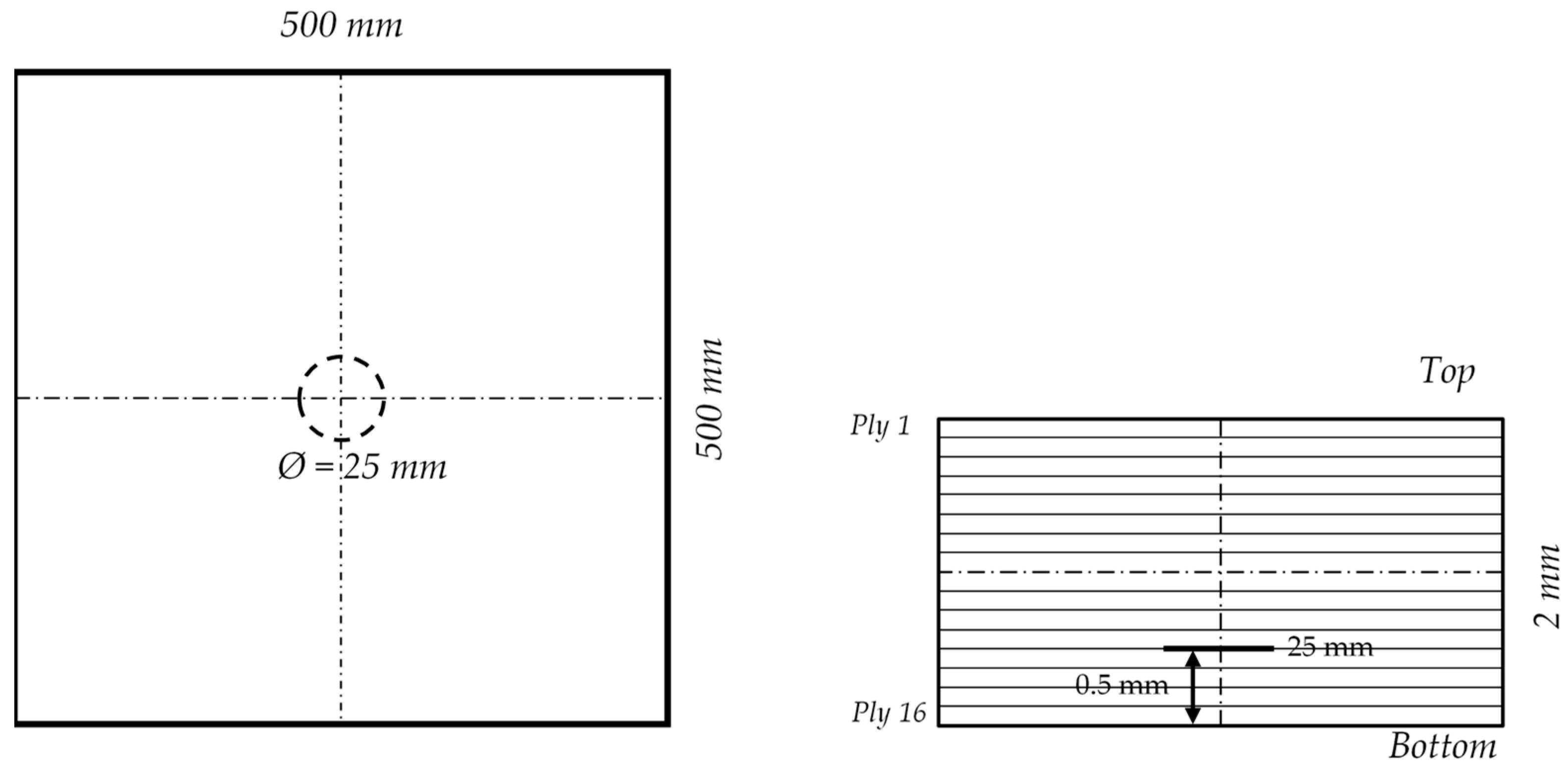
A CYCOM 5320-1/IM7 12K prepreg was used to manufacture the composite specimen. The simulated delamination was introduced by inserting a Teflon film into the composite plate before curing it in a hot press machine. A circular Teflon film (25 mm in diameter) between plies 12 and 13 was inserted to create the delamination. The thickness of the Teflon film was 50 μm. The depth of the Teflon insert was based on the experimental results in Reference [8]. The delamination size was determined from the practical application, where the critical delamination size for growth monitoring was around 25 mm in diameter. Figure 2 shows a schematic of a 2-mm quasi-isotropic composite plate with purpose-built delamination. The experimental setup and curing cycle of the specimen manufacturing are given in Figure 3.
Ultrasonic nondestructive testing (NDT) was conducted on the composite plate to verify and image the simulated delamination. An ultrasonic immersion tank was used to inspect the specimen. In the experiment, a 10-MHz, 25.4-mm focused transducer was used. First, a full-specimen NDT inspection was conducted, and there were no other manufacturing defects other than the simulated delamination. Then, a small-area scan was performed to detect and image the simulated delamination. The scan area was 50 mm × 50 mm. After an initial scan with the focus on the top surface of the sample, the transducer was refocused at the depth of the Teflon film for a clearer C-scan image. Figure 4 shows the B-scan and C-scan images of the NDT results. The C-scan image shows the presence of the simulated delamination in the composite plate. The depth of the delamination can be observed in the B-scan image (0.5 mm away from the bottom surface). In the C-scan image, the size and shape of the delamination can be clearly observed. Therefore, the simulated delamination could be detected and quantified from the NDT detection, which was consistent with the design.

3.1.2. Impact Damage Due to Low-Velocity Impact

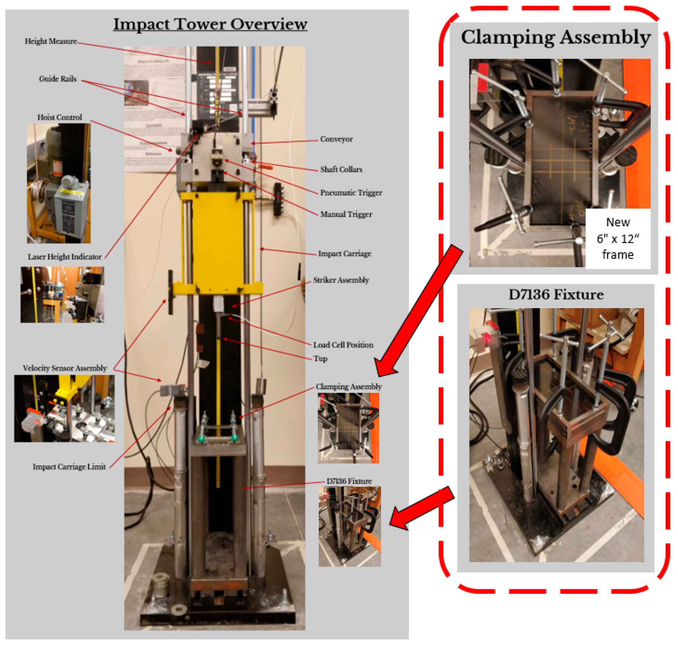
A small coupon was cut from the 2-mm quasi-isotropic composite plate and was used to conduct the impact testing. A drop-weight impact tower was utilized to induce an impact on a fixed composite coupon. In this study, the coupon dimensions were changed from 152 mm × 102 mm (ASTM D7136 standard dimensions) to 304 mm × 204 mm. Note that the in-plane dimensions of the coupon were twice the size of the ASTM D7136 standard in order to make the panel size more realistic for guided wave propagation. In order to accommodate the larger plate, two rectangular frames were designed and manufactured. They were clamped to the ASTM D7136 fixture to conduct impact tests on the same drop-weight impact tower. The modified experimental setup is shown in Figure 5. The controlled impact event was recorded by a piezoelectric load cell, which could accurately record the data of the applied impact force (energy absorbed by the specimen during the impact event).
The details of the impact test are given in Table 1, which indicates that the coupon was impacted using a 3.06-kg impactor with a potential energy of 16.69 J. This energy was chosen using engineering judgment to try to obtain a 25-mm-impact damage size in the 2-mm-thick quasi-isotropic composite coupon.
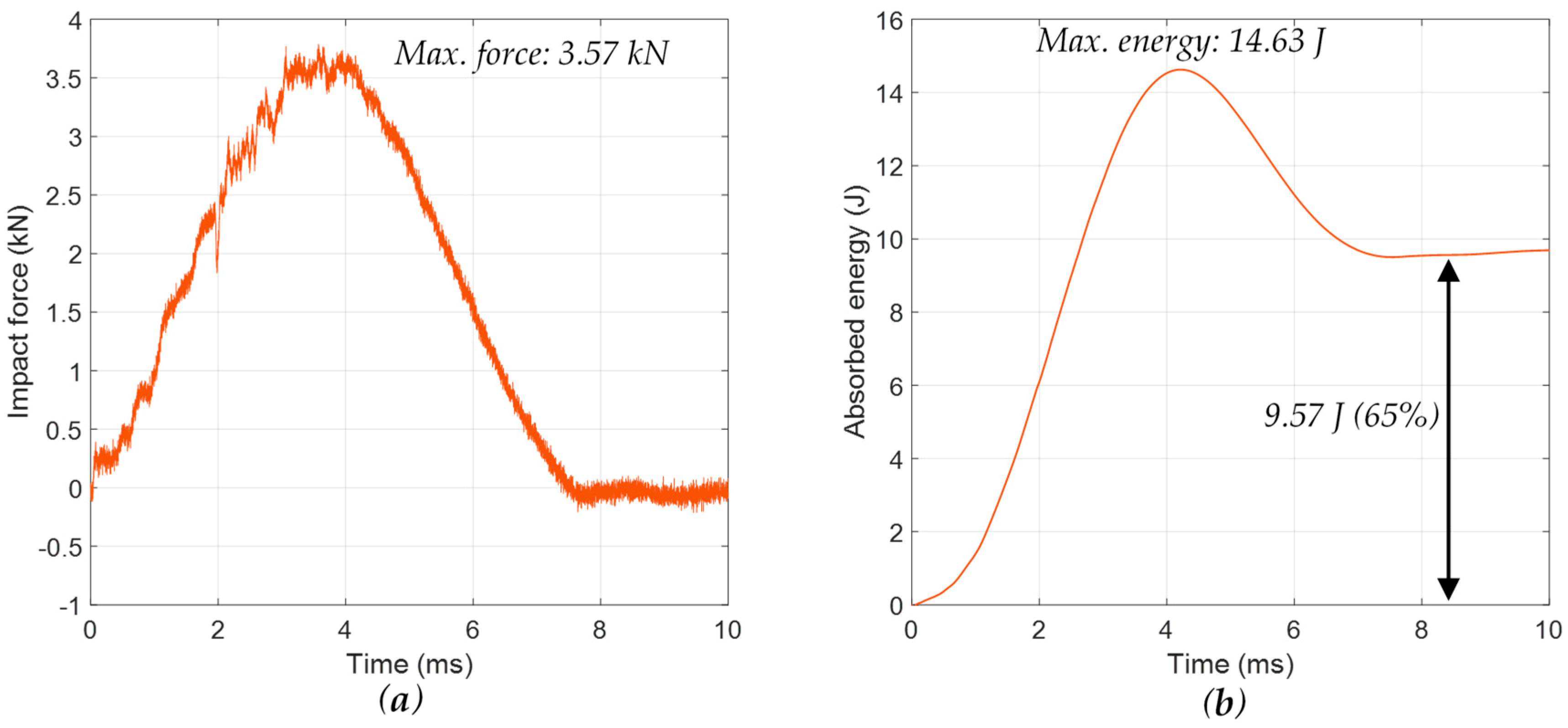
The force–time history and absorbed energy of the impact event are given in Figure 6. The load curve shows peaks at a certain maximum load and is parabolic in shape. When there are irregularities in the parabolic shape of the load curve, this indicates that the specimen has undergone extensive internal damage [30]. The maximum-recorded contact force of this impact event was 3.57 kN. The energy–time plot given in Figure 6 was taken from the force–time curve through integration of the data. The energy–time plot described the peak energy experienced and energy absorbed by the specimen. Here, the energy absorbed was the difference between the value at the end of the plot and the initial value. The difference between the peak energy observed and the energy absorbed could be used to determine the efficiency of energy absorption of the material. Furthermore, the energy–time history was able to demonstrate the percentage of impact energy that was absorbed by the specimen to create the irreversible process of damage. It was found that over 65% of the impact energy was absorbed by the specimen where the 25-mm-impact damage was formed.
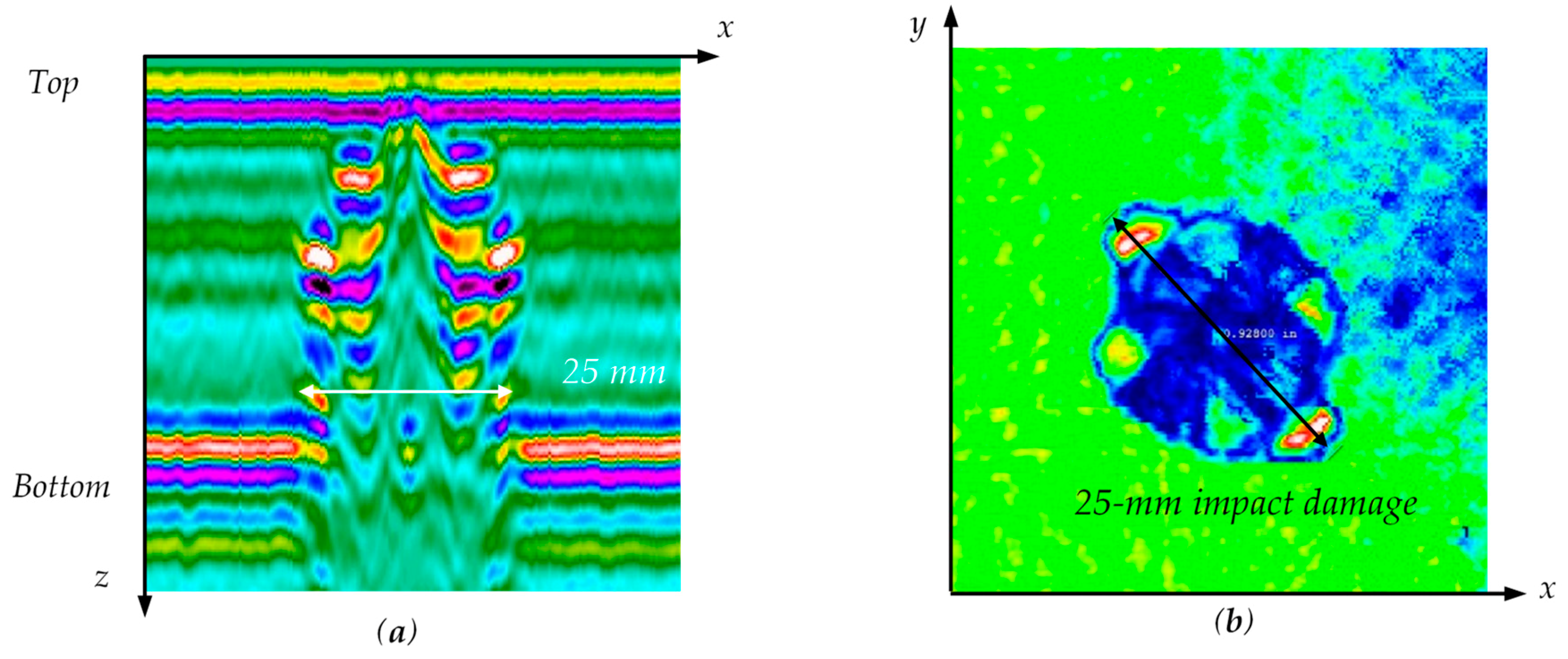
After the impact testing, an ultrasonic NDT inspection was conducted using a 10-MHz, 25.4-mm focused transducer. After an initial scan with the focus on the top surface of the specimen, the transducer was refocused at the depth where the impact damage size was the maximum for a clearer C-scan image. The NDT inspection results are shown in Figure 7. Multiple impact-induced delaminations across the thickness were observed in the B-scan results. It was found that the size of the impact damage obtained was around 25 mm (C-scan results).

3.2. Pure Mode Generation Using ABT–ABT

The tuning angle of the 2-mm quasi-isotropic CFRP composite plate was calculated for the pure-mode guided wave generation. The material properties were measured experimentally using the ultrasonic immersion technique described in Reference [31] (given in Table 2).
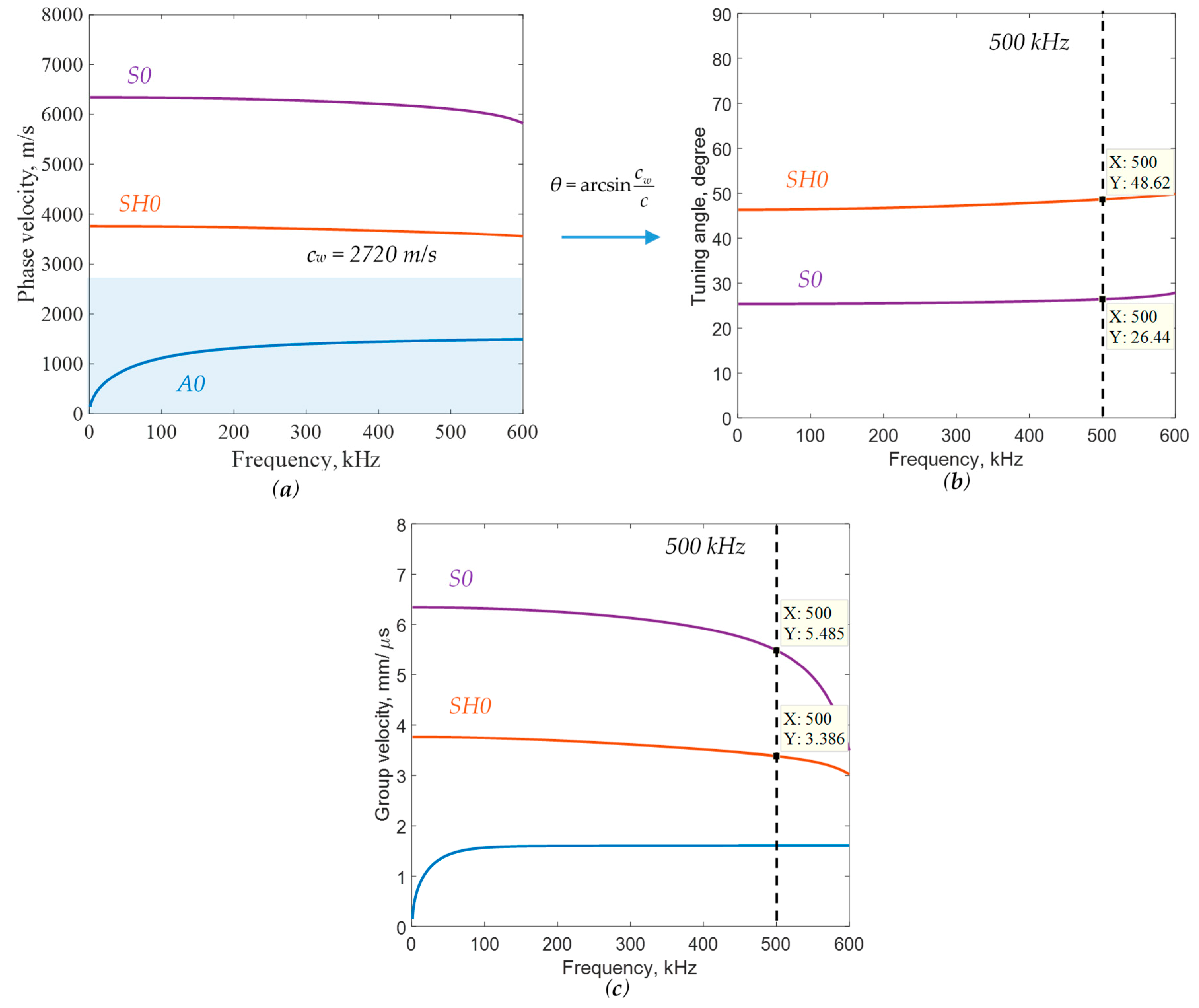
Dispersion curves of the 2-mm quasi-isotropic CFRP composite plate were obtained using the semi-analytical finite element (SAFE) method [5]. For the SAFE approach, 32 one-dimensional (1D) quadratic elements across the thickness direction were used to ensure the convergence of the solution. Phase–velocity dispersion curves of the 2-mm quasi-isotropic CFRP composite plate in the 0° direction are shown in Figure 8a. In this study, the wedge velocity of the adjustable wedge was 2720 m/s, and the ABT central frequency was 500 kHz. The theoretical tuning angle was calculated based on Equation (1), as shown in Figure 8b. It was found that the wave modes could not be excited when the phase velocities were below cw. At 500 kHz, S0 mode and SH0 mode could be excited, and the ABT tuning angles were around 26° and 49°, respectively. Therefore, the incident angles should be set to 26° and 49° to excite pure S0 mode and SH0 mode in the 2-mm quasi-isotropic CFRP composite plate. In addition, the group–velocity dispersion curves are given in Figure 8c, and the group velocities of S0 mode and SH0 mode at 500 kHz were 5.49 mm/μs and 3.39 mm/μs, respectively. These group velocities were used to validate the generated guided waves in the composite plate.

3.2.1. Pure S0 Mode Generation

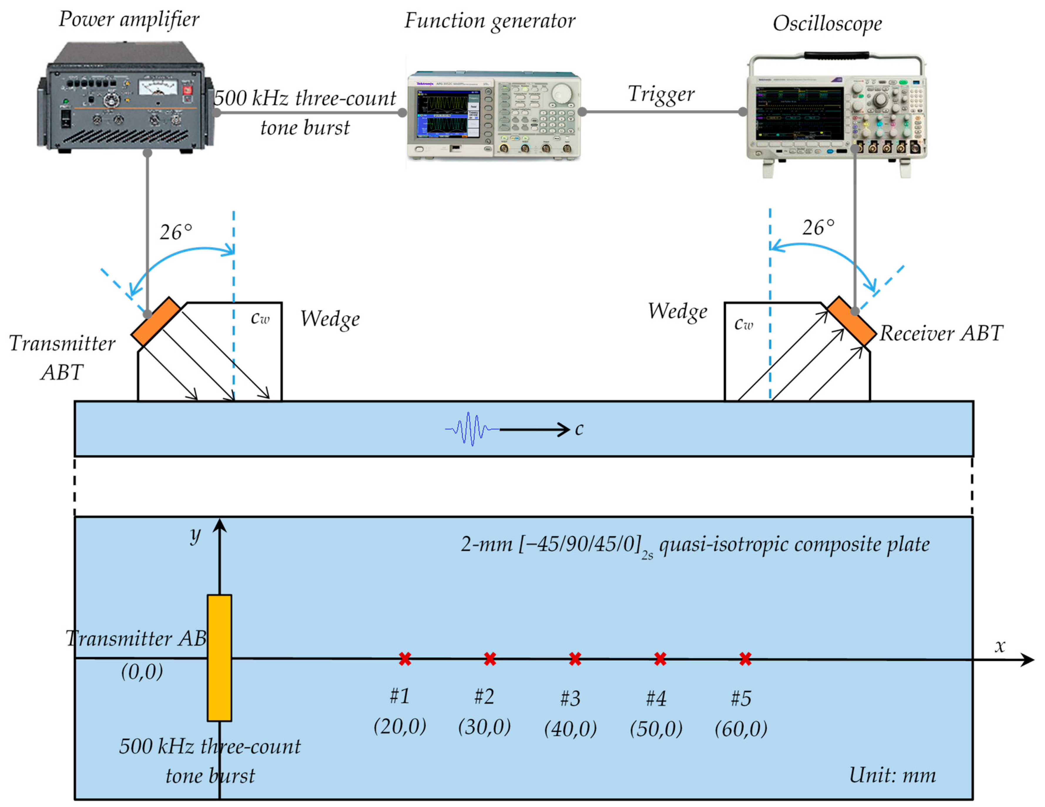
First, the adjustable ABT pair was used to generate pure S0 mode in the 2-mm quasi-isotropic CFRP composite plate. To generate and receive the pure S0 mode in the 2-mm quasi-isotropic composite plate, 500 kHz broadband angle beam transducers (A413S-SB, Olympus, USA) mounted on adjustable wedges (ABWX-2001, Olympus, USA) were used as the transmitter and the receiver. Figure 9 illustrates the pitch–catch experimental setup for guided wave generation and detection using ABT–ABT. The coupling between wedges and the specimen was attained with coupling gel (Olympus Sound Safe). For the excitation of pure S0 mode at 500 kHz, the incident angle of the wedge was set to 26° based on Snell’s law. The excitation signal applied to the transmitter ABT was a narrow-band three-count tone burst at a central frequency of 500 kHz generated by a function generator (AFG3052C, Tektronix, USA) and amplified by a high-speed bipolar amplifier (HSA4014, NF, Japan). The response signals from the receiver ABT were collected by a digital oscilloscope (MDO3024, Tektronix, USA), which used 100 averages to improve the signal-to-noise ratio. The function generator also sent a trigger signal to the oscilloscope for synchronization.
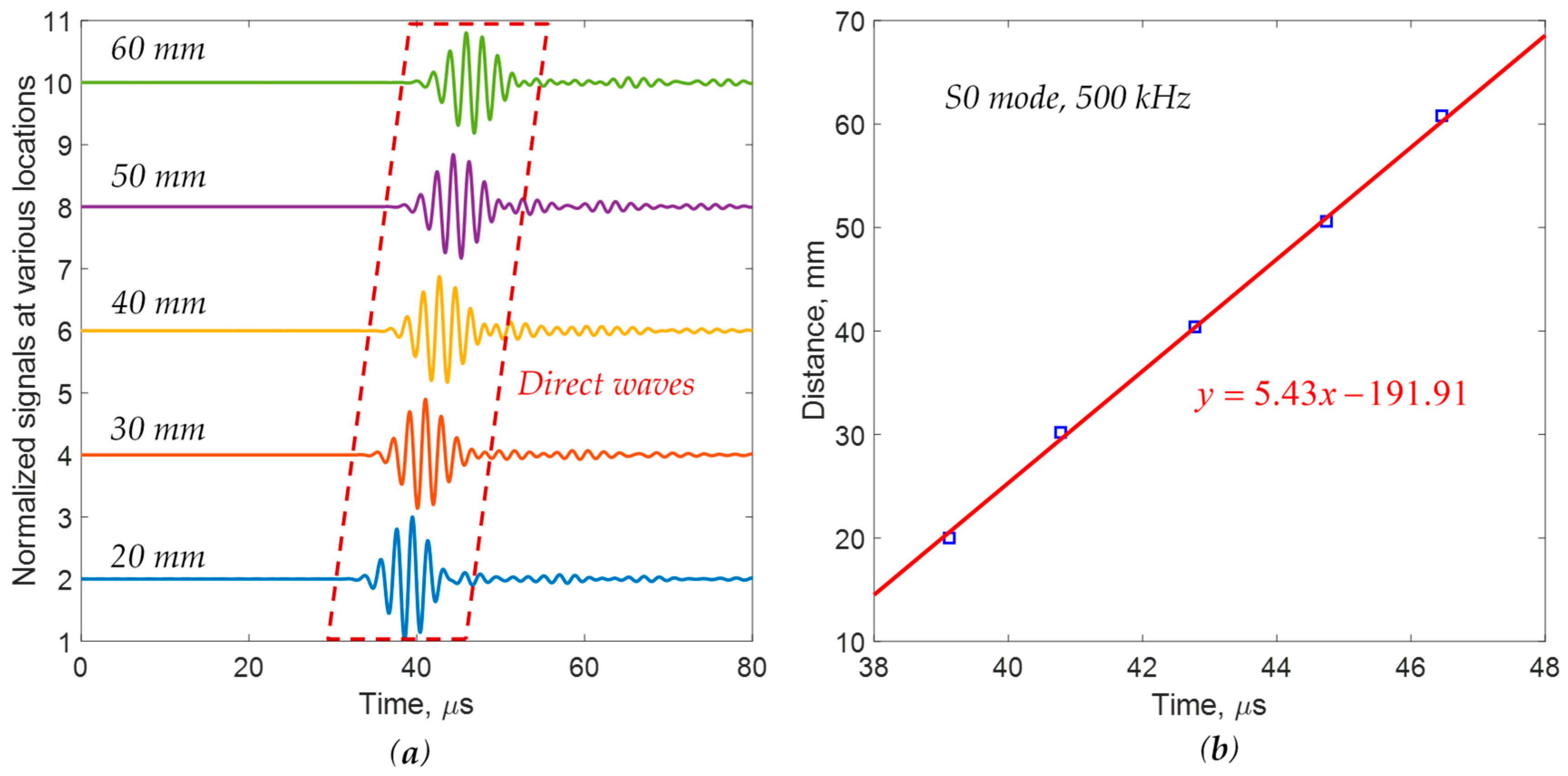
To validate the excited guided wave, the response signals at five different locations were measured by moving the receiver ABT at a constant interval of 10 mm, as presented in Figure 9. Experimental group velocity measurements of the S0 mode excitation are shown in Figure 10.
The waveforms at various locations are shown in Figure 10a. It was found that strong and nondispersive wave packets were obtained. The time of flight (TOF) of the direct wave packet was determined for each location and plotted as a function of distance from the excitation, as shown in Figure 10b. First, the received signals were processed using a continuous wavelet transform (CWT) to extract the signal envelopes. Then, the TOF was determined at the time position corresponding to the maximum amplitude of the signal envelope. Linear regression was used to estimate group velocity, yielding a value of 5.43 mm/μs, which agreed with the theoretical S0-mode group velocity of 5.49 mm/μs at 500 kHz, as shown in Figure 8c. Therefore, the excited guided wave in the 2-mm quasi-isotropic CFRP composite plate was in pure S0 mode, as expected.

3.2.2. Pure SH0 Mode Generation

Second, the ABT–ABT was used to excite a pure shear horizontal (SH0) wave in the 2-mm quasi-isotropic CFRP composite plate. The same pitch–catch experiment (shown in Figure 9) was conducted. Only the incident angles of the wedges were adjusted to the theoretical tuning angle of SH0 mode. For the excitation of pure SH0 mode at 500 kHz, an incident angle of 49° was used, based on Snell’s law. The excitation signal applied to the transmitter ABT was a narrow-band three-count tone burst at a central frequency of 500 kHz.
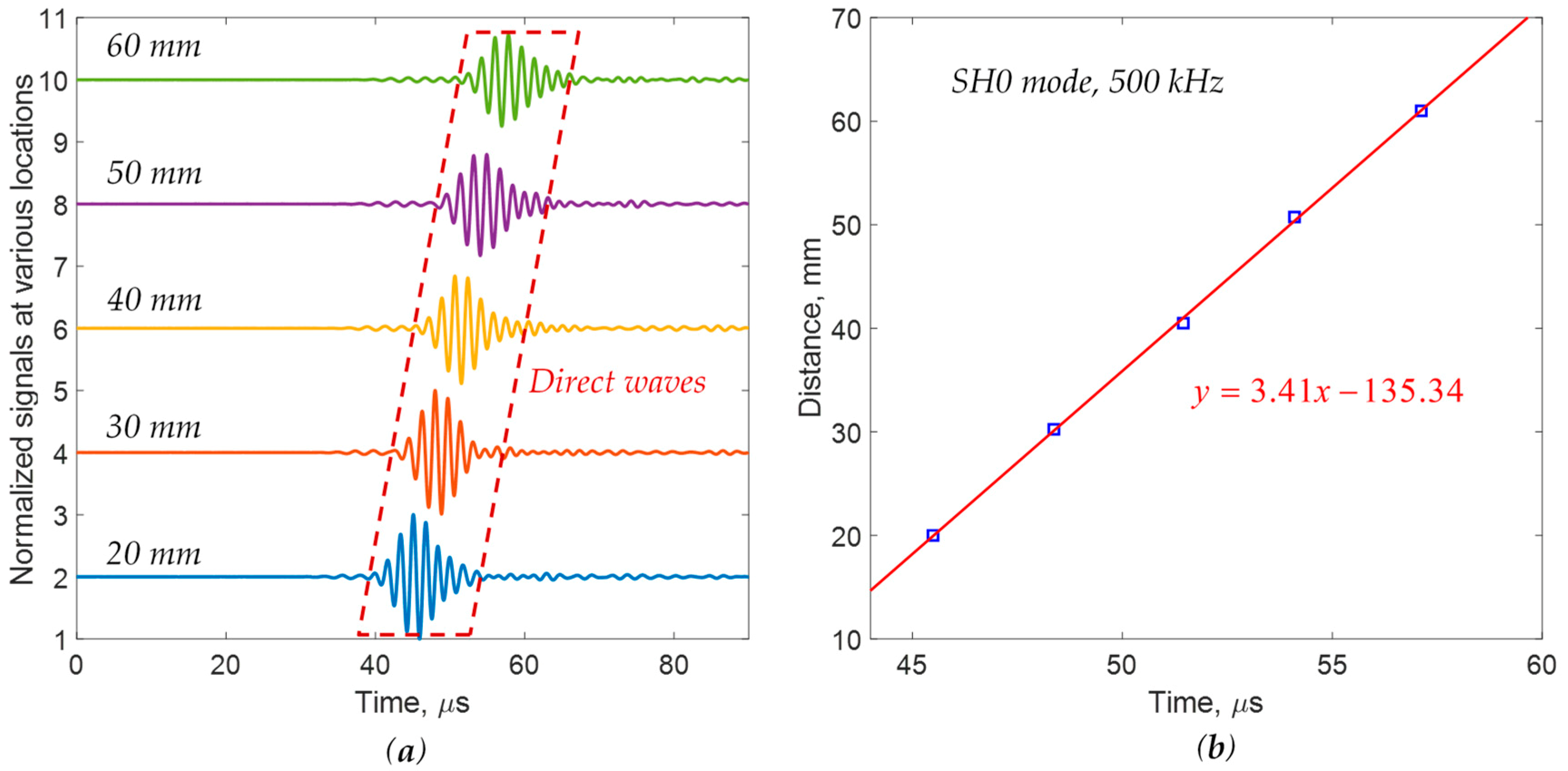
To validate the generated pure-mode guided wave, the response signals at five different locations were measured, as shown in Figure 11a. It was found that strong single-wave packets were received at all of the locations. The TOF of the direct wave packet was determined for each location and plotted as a function of distance, as shown in Figure 11b. Similarly, linear regression was used to estimate the group velocity, yielding a value of 3.41 mm/μs, which compared favorably to the theoretical SH0-mode group velocity of 3.39 mm/μs at 500 kHz. Therefore, the excited guided wave in the 2-mm quasi-isotropic CFRP composite plate was in pure SH0 mode, as expected. The experimental results demonstrate that although the ABT excitation consisted of pressure waves, SH0 was successfully generated due to the anisotropy of the quasi-isotropic composite layup.

3.3. Damage Detection Using Multiple Pure-Mode Guided Waves

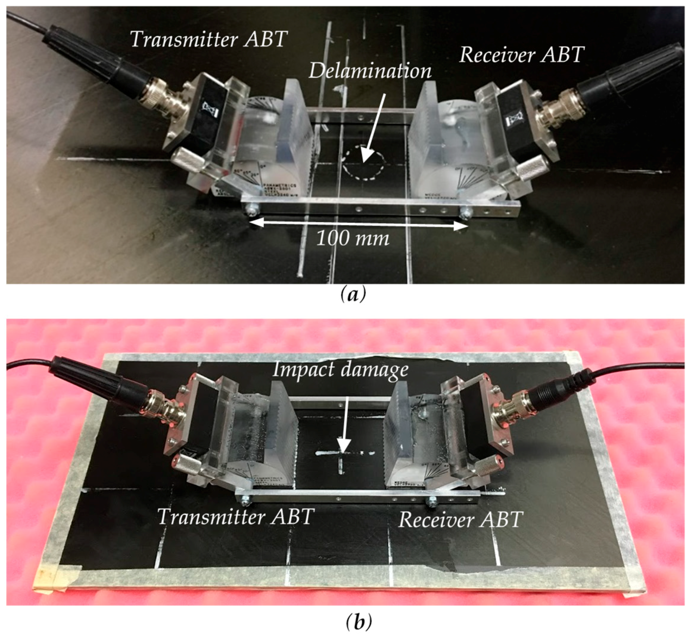
In this section, pure S0 and SH0 modes generated by the ABT–ABT were utilized to detect the simulated delamination and actual impact damage in the 2-mm quasi-isotropic composite plate. The experimental setup for damage detection in the 2-mm quasi-isotropic composite plate is shown in Figure 12. A 100-mm distance was ensured between the transmitter ABT and the receiver ABT using a rigid frame. For the inspection of pure S0 mode at 500 kHz, the incident angle of the wedge was set to 26°, while an incident angle of 49° was used for the excitation of pure SH0 mode. A narrow-band three-count tone-burst excitation at a central frequency of 500 kHz was used as the input signal for the transmitter ABT. In the experiment, the measurements were conducted by placing the ABT–ABT on the pristine area, delamination, and impact damage.

3.3.1. Damage Detection Using Pure S0 Mode

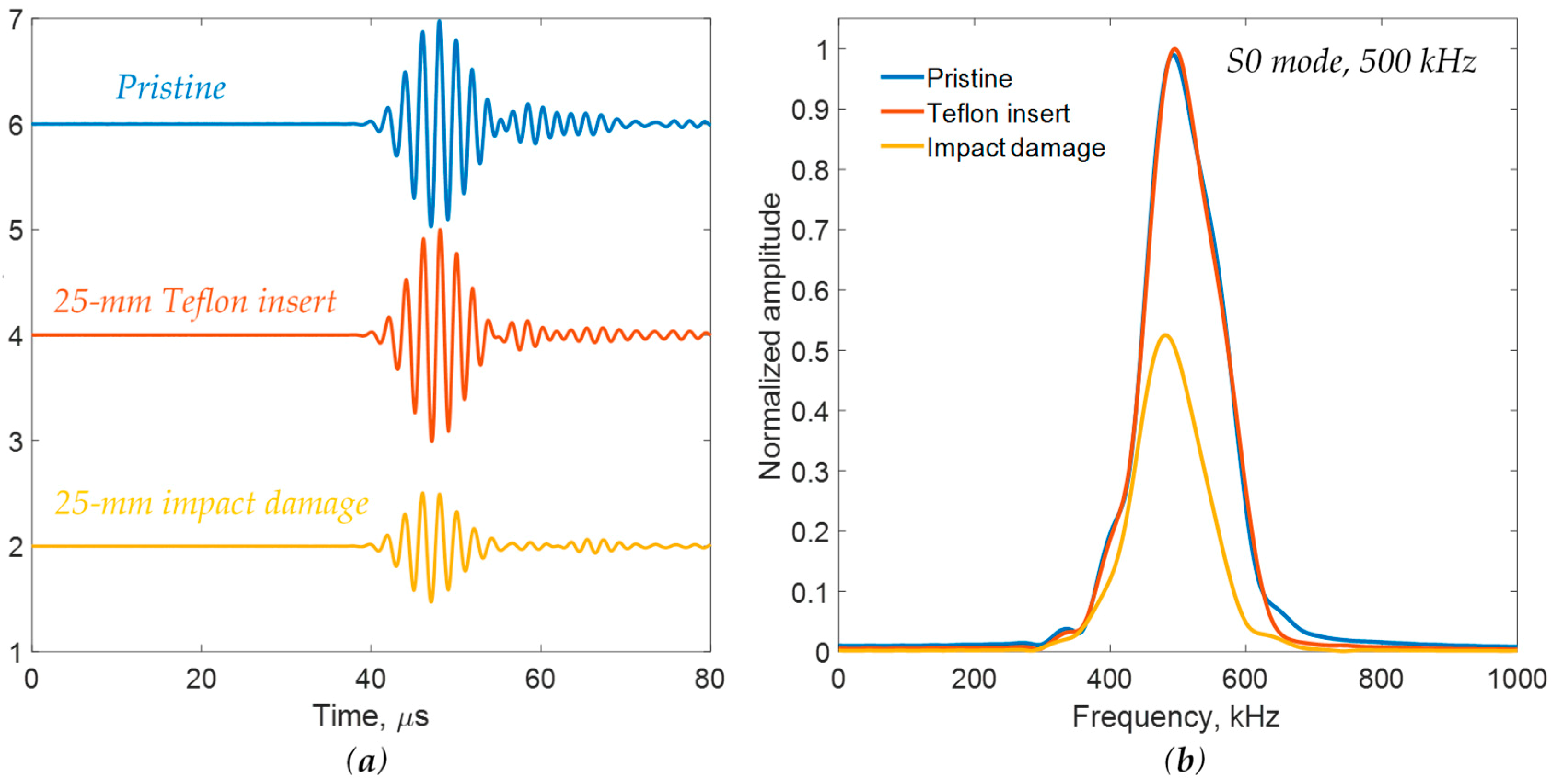
Pure S0 mode was used to detect the delamination simulated by the Teflon insert and the actual impact damage. A signal comparison between the pristine area, the delamination simulated by the Teflon insert, and the actual impact damage is shown in Figure 13.
Strong and nondispersive wave packets of S0 mode were observed in all cases, as depicted in Figure 13a. A high signal-to-noise ratio was obtained even in the presence of damage. It was found that no obvious amplitude change was observed in the case of the Teflon insert, whereas a significant amplitude drop was clearly noted due to the presence of impact damage. The frequency spectrums were calculated by using time windowing on the acquired signals to obtain the main wave packet and remove the trailing waves. Similarly, the same phenomena were noted in the frequency spectrum, as shown in Figure 13b. Therefore, pure S0 mode was sensitive to the actual impact damage but not sensitive to the delamination simulated by the Teflon insert. This was because the impact damage, in the form of matrix cracking, fiber breakage, and interlaminar delamination, significantly reduced local stiffness. Therefore, impact damage caused a strong amplitude decrease for the S0-mode guided wave.

3.3.2. Damage Detection Using Pure SH0 Mode

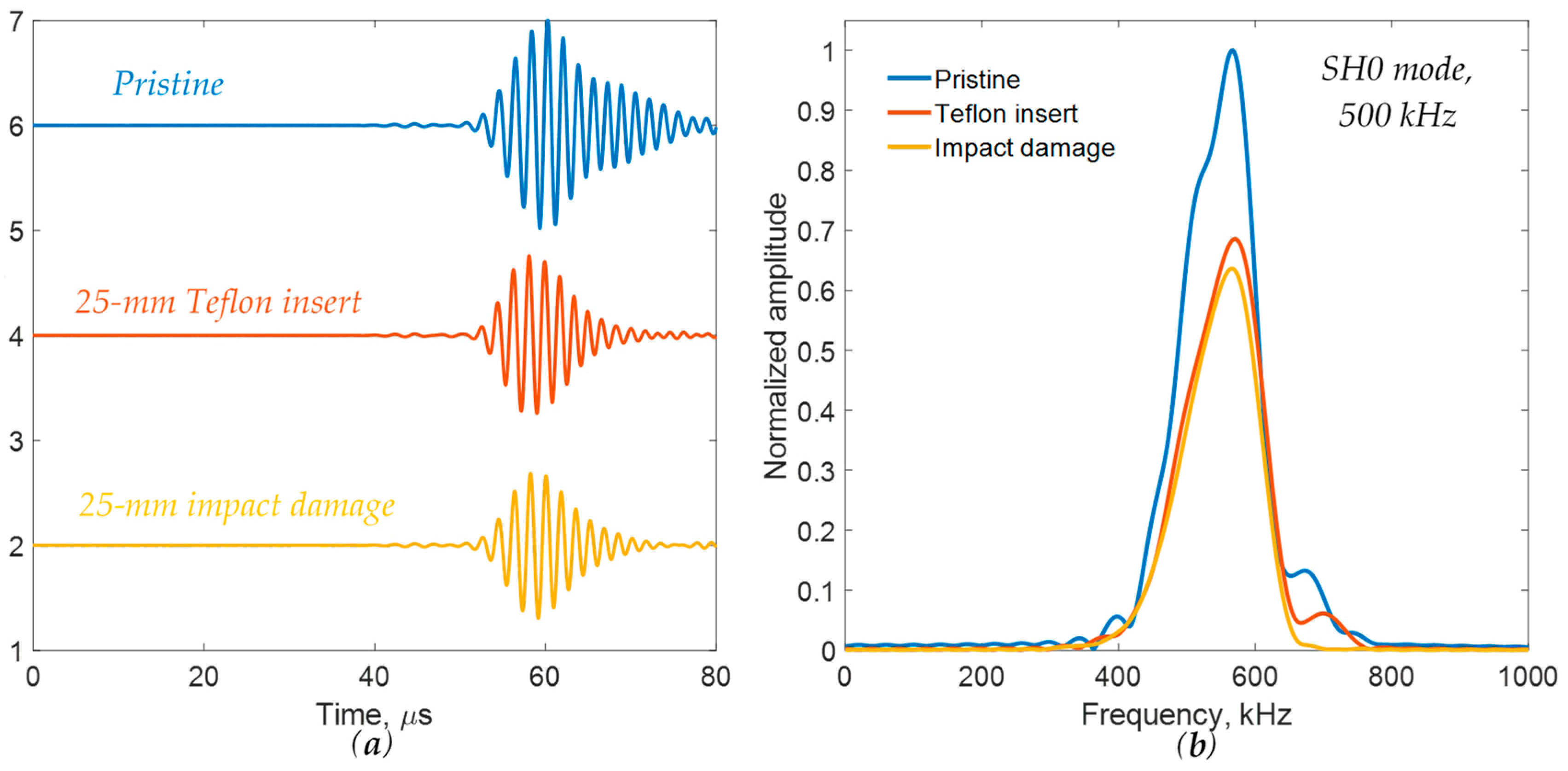
Similarly, the pure SH0 mode generated by the adjustable ABT pair was used to detect the delamination simulated by the Teflon insert and the actual impact damage. Figure 14 shows a signal comparison between the pristine area, the delamination simulated by the Teflon insert, and the impact damage using pure SH0 mode. Strong wave packets of pure SH0 mode were observed for all three cases. It was found that large amplitude drops were clearly observed for both the Teflon insert and the impact damage. The frequency spectrums were calculated using time windowing on the acquired signals to obtain the main wave packet and remove the trailing waves. Similarly, amplitude drops were noted in the frequency spectrums. Therefore, SH0 mode was sensitive to both the delamination simulated by the Teflon insert and the actual impact damage. However, SH0 mode could not separate the delamination and impact damage since the same amplitude drop was observed for both cases.
To distinguish between damage types, the pure S0 mode and SH0 mode had to be used together. This is because the pure S0 and SH0 modes were both sensitive to actual impact damage, whereas only the pure SH0 mode was sensitive to the delamination simulated by the Teflon insert. This was related to the motion characteristics of the respective mode shapes and the corresponding wavelengths. Thus, the use of the pure S0 and SH0 modes allowed for damage separation that would not have been possible otherwise.

4. Detection of Various Damage Types Using ABT–ABT on a 3-mm Quasi-Isotropic Composite Plate

In this section, a 3-mm quasi-isotropic CFRP composite plate was used to validate the proposed method. Multimode guided wave detection was utilized to distinguish between delamination and impact damage.

4.1. Composite Specimen

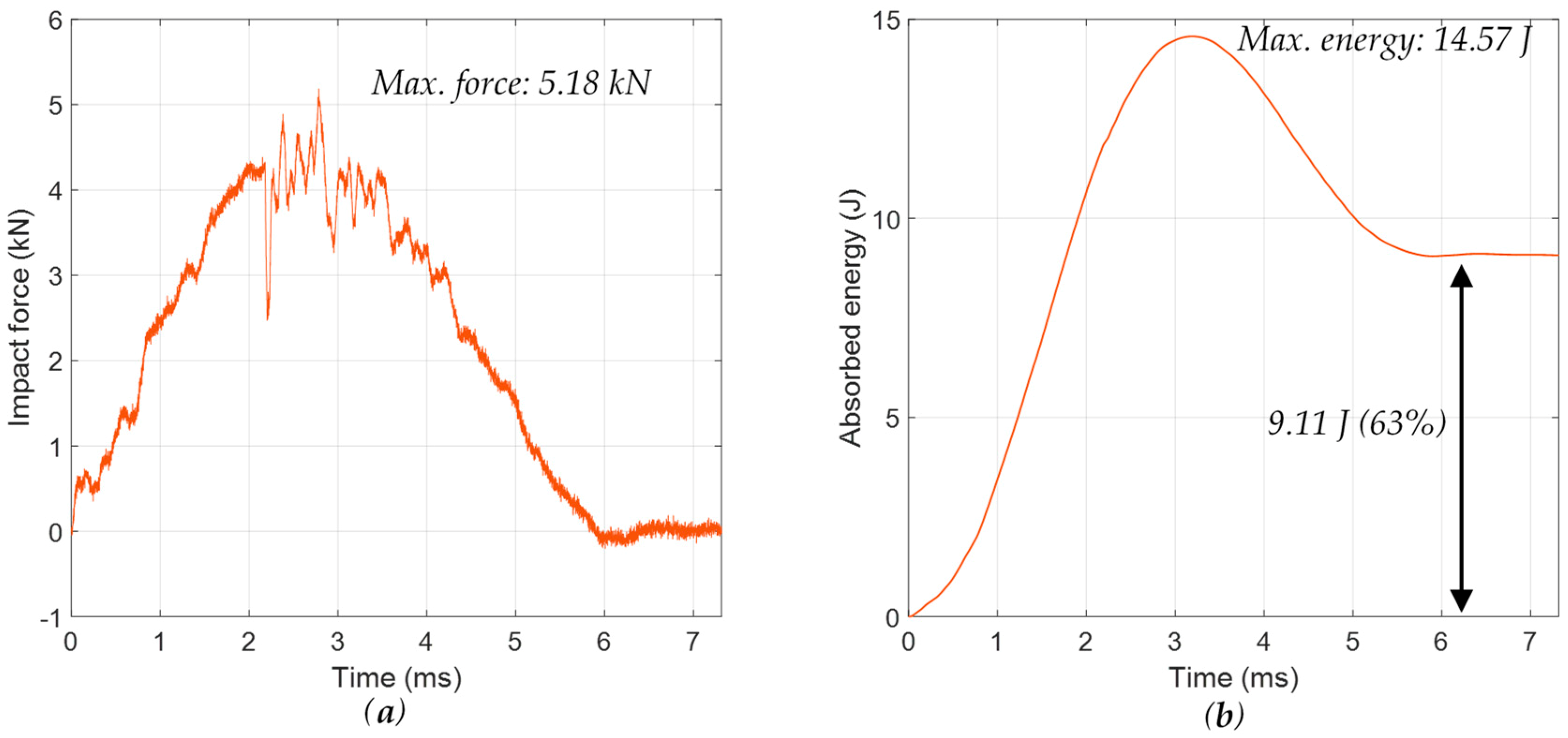
A 3-mm-thick in-house quasi-isotropic CFRP composite plate with a stacking sequence of [−45/90/45/0]3s was investigated. The dimension of the specimen was 500 mm × 500 mm × 3 mm. There were two different types of damage in the 3-mm quasi-isotropic composite plate, including delamination simulated by the Teflon insert and impact damage. A hot press machine was used to manufacture the composite specimens, as shown in Figure 3. The simulated delamination was created by inserting a circular Teflon film (25 mm in diameter) between plies 20 and 21, which was 0.5 mm away from the bottom surface of the specimen. For the impact damage, a 304 mm × 204 mm coupon was cut from the 3-mm quasi-isotropic composite plate and was used to conduct the impact testing using a drop-weight impact tower. The details of the impact test are given in Table 3. This table indicates that the coupon was impacted using a 3.06-kg impactor with a potential energy of 17.56 J. This energy was chosen using engineering judgment to try to obtain a 25-mm-impact damage size in the 3-mm-thick quasi-isotropic composite coupon. The force–time history and the absorbed energy of the [−45/90/+45/0]3S coupon are given in Figure 15.
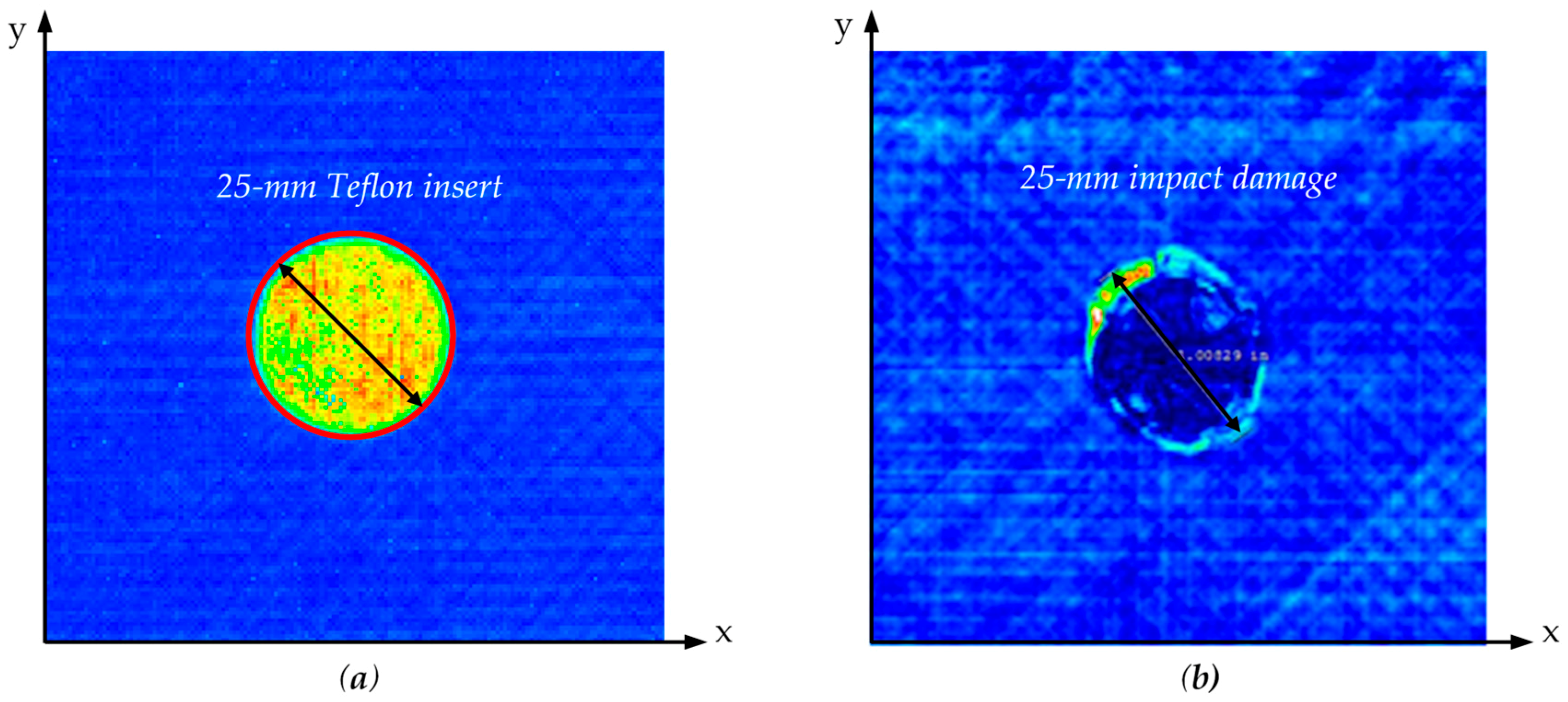
An ultrasonic C-scan was performed on the 3-mm-thick quasi-isotropic composite plate to verify and image the simulated delamination and the impact damage. An ultrasonic immersion tank was used to inspect the specimen. In the experiment, a 10-MHz, 25.4-mm focused transducer was used. First, a full-specimen NDT inspection was conducted, and there were no other manufacturing defects. Then, a small-area scan was performed to detect and image the delaminations simulated by the Teflon inserts and the impact damage. The scan area was 75 mm × 75 mm. After an initial scan with the focus on the top surface, the transducer was refocused at the depth of the Teflon film and the maximum impact damage for a clearer C-scan image. Figure 16 shows the C-scan images of the NDT results. The C-scan images show the presence of the 25-mm delamination and the 25-mm impact damage. Therefore, the simulated delamination and impact damage were successfully detected and quantified in the NDT detection.

4.2. Pure Mode Generation

The tuning angle of the 3-mm quasi-isotropic CFRP composite plate was calculated using the SAFE method for pure-mode guided wave excitation.
Phase–velocity dispersion curves of the 3-mm quasi-isotropic CFRP composite plate in the 0° direction are shown in Figure 17a. The ABT tuning angle was calculated with Equation (1), as shown in Figure 17b. At 500 kHz, SH0 mode could be excited, and the tuning angle was around 48°. However, the S0 mode could not be generated at 500 kHz, since its phase velocity was smaller than the wedge velocity of 2720 m/s, as shown in Figure 17a. Therefore, the excitation frequency had to be reduced in order to generate pure S0 mode in the 3-mm quasi-isotropic composite plate. In this study, the excitation frequency of the pure S0 mode was set to 300 kHz, and it was found that S0 mode was nondispersive at this frequency. In addition, a broadband angle beam transducer with a central frequency of 500 kHz was used in the experiment, and the 300-kHz excitation frequency of the S0 mode was close to the central frequency. At 300 kHz, the tuning angle of the S0 mode was about 26°. Therefore, the incident angles of the ABT–ABT were set to 26° and 48°, respectively, to excite pure S0 mode at 300 kHz and SH0 mode at 500 kHz in the 3-mm quasi-isotropic CFRP composite plate.

4.2.1. Pure S0 Mode Generation

The ABT–ABT was used to generate a pure S0 mode at 300 kHz in the 3-mm quasi-isotropic CFRP composite plate. A pitch–catch experiment was conducted to measure the group velocity. For the excitation of pure S0 mode at 300 kHz, the incident angles were set to 26° (based on Snell’s law). The excitation signal applied to the transmitter ABT was a narrow-band three-count tone burst at a central frequency of 300 kHz.
To validate the generated guided wave, the response signals at five different locations were measured, as shown in Figure 18a. Strong response signals with high signal-to-noise ratios were obtained. It was noted that the wave packet was nondispersive. The TOF of the direct wave packet was determined and plotted as a function of distance, as shown in Figure 18b. Linear regression was used to estimate the experimental group velocity, yielding a value of 5.84 mm/μs, which agreed with the theoretical S0-mode group velocity of 5.87 mm/μs at 300 kHz obtained from the SAFE approach [5]. Therefore, pure S0 mode at 300 kHz was successfully generated in the 3-mm quasi-isotropic composite plate.

4.2.2. Pure SH0 Mode Generation

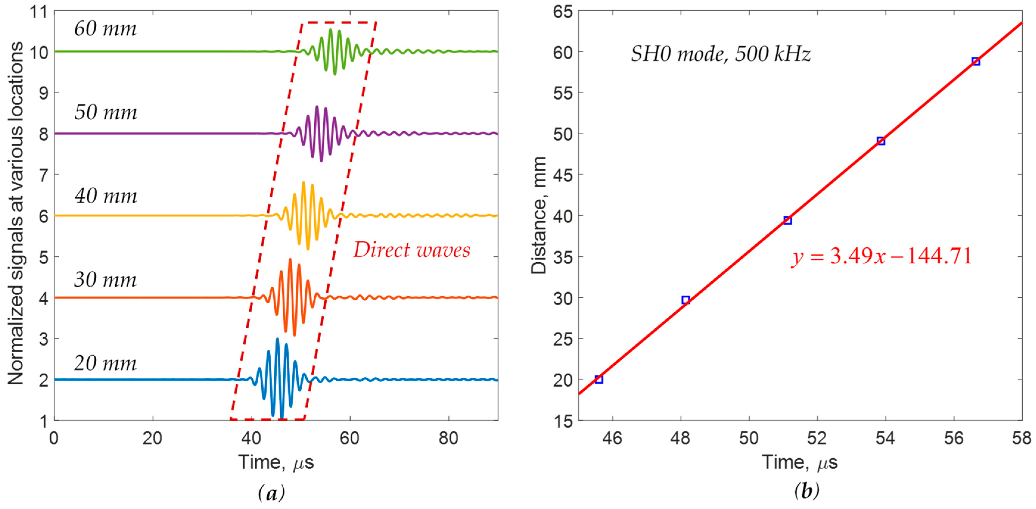
The ABT–ABT was used to excite a pure SH0 mode in the 3-mm quasi-isotropic CFRP composite plate. For the excitation of pure SH0 mode at 500 kHz, the incident angle was set to 48°. The same pitch–catch experiment was repeated to collect the response signals at various locations at a constant interval of 10 mm.
The response signals at five different locations were measured, as shown in Figure 19a. The TOF of the direct wave packet was calculated and plotted as a function of distance, as shown in Figure 19b. Similarly, linear regression was used to estimate the group velocity, yielding a value of 3.49 mm/μs, which agreed with the theoretical SH0-mode group velocity of 3.39 mm/μs at 500 kHz in the 3-mm quasi-isotropic composite plate. Therefore, the excited guided wave in the quasi-isotropic CFRP composite plate was in pure SH0 mode, as expected. The experimental results demonstrated that the ABT–ABT could successfully generate pure S0 mode and SH0 mode guided waves in the 3-mm quasi-isotropic composite plate.
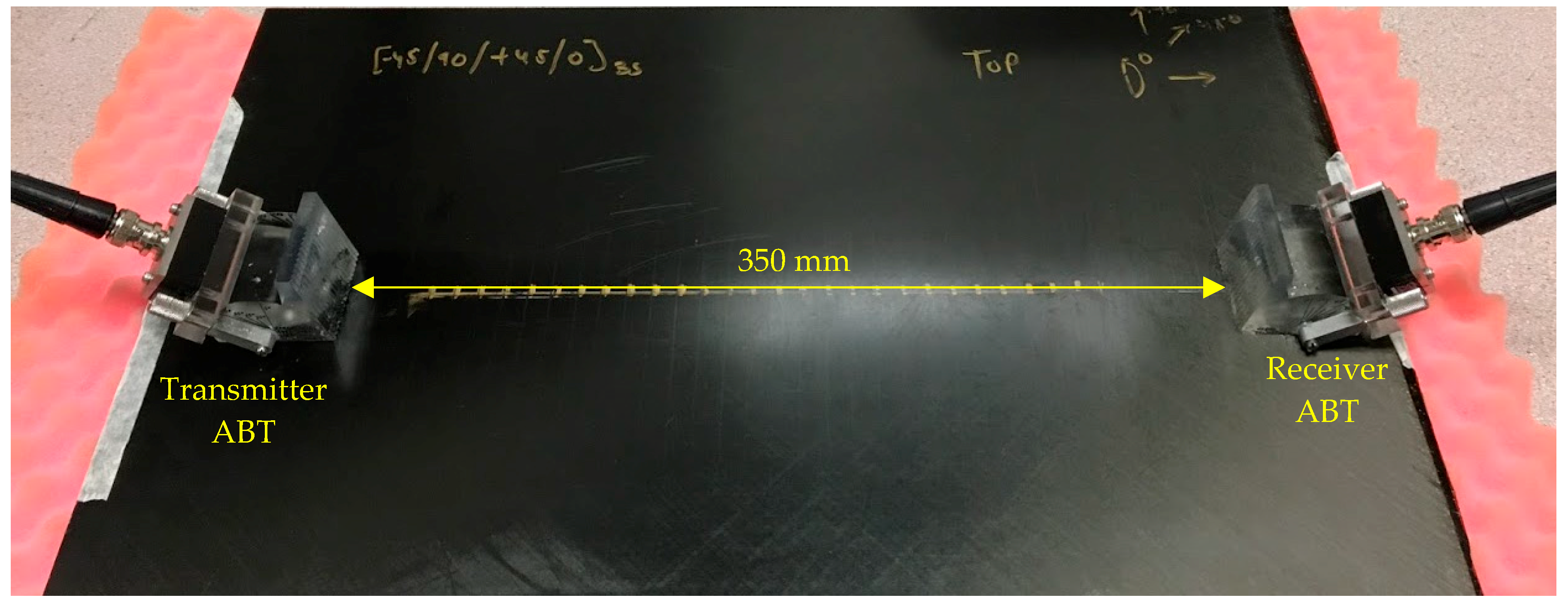
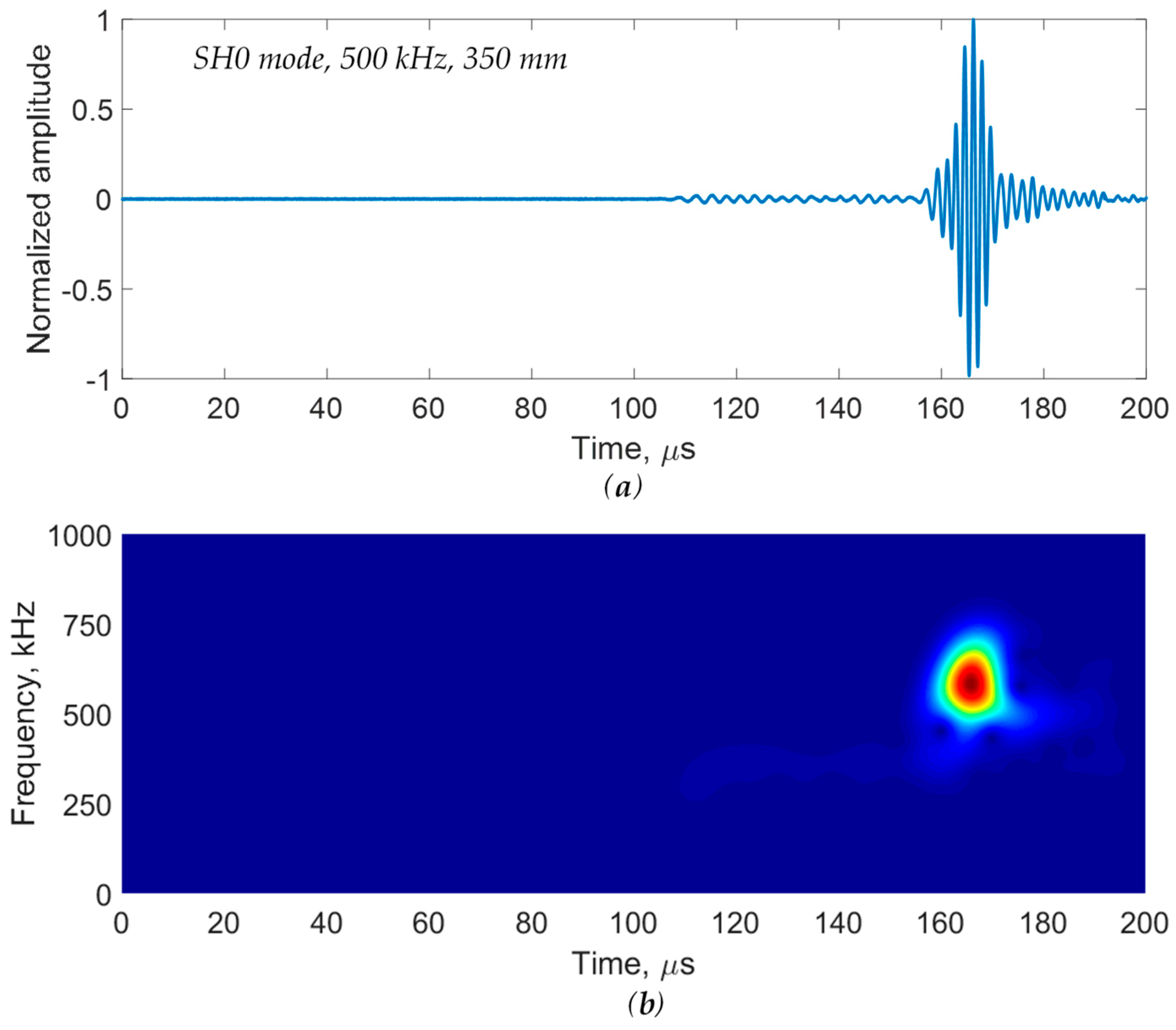
In order to demonstrate the feasibility of this technique for damage detection over a long distance, a pitch–catch experiment was conducted on the 3-mm quasi-isotropic CFRP composite plate using the ABT–ABT. The long-distance experimental setup is shown in Figure 20. The distance between the transmitter ABT and the receiver ABT was 350 mm. The measured signal at a 350-mm distance is displayed in Figure 21. Figure 21a shows the time-domain signal, and the short-time Fourier transform (STFT) spectrogram is given in Figure 21b. From the time-domain signal, it was observed that a strong SH0-mode signal was measured even at a far distance of 350 mm using the ABT–ABT. A strong SH0-mode wave packet was also observed in the STFT spectrogram, as shown in Figure 21b.

4.3. Multimode Guided Wave Detection

The pure S0 mode at 300 kHz and the pure SH0 mode at 500 kHz were used to detect the delamination simulated by the Teflon insert and the impact damage in the 3-mm quasi-isotropic composite plate. The experimental setup is presented in Figure 22. For the inspection of pure S0 mode at 300 kHz, an incident angle of 26° was used, while an incident angle of 48° was used for the inspection of pure SH0 mode at 500 kHz. Similarly, three measurements were conducted by placing the ABT–ABT on the pristine area, delamination, and impact damage.

4.3.1. Damage Detection Using Pure S0 Mode

A signal comparison between the pristine area, the delamination by the Teflon insert, and the impact damage in the 3-mm quasi-isotropic composite plate is shown in Figure 23.
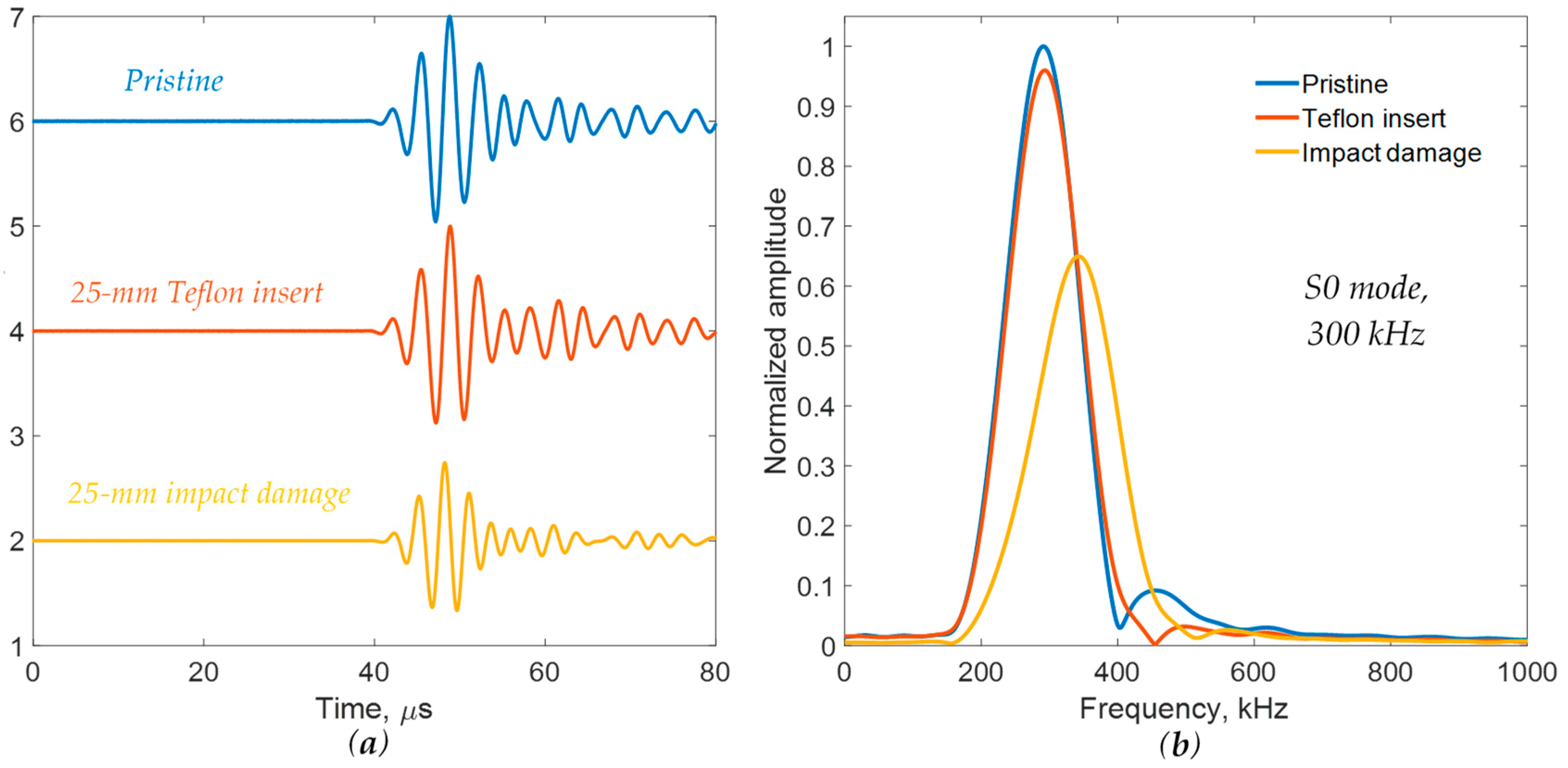
Figure 23a shows the strong single wave packets for S0 mode in all cases. A high signal-to-noise ratio was obtained. It was found that no obvious amplitude change was observed for the case of the Teflon insert, whereas a large amplitude drop could be clearly observed due to the presence of impact damage. The frequency spectrums were calculated using time windowing on the acquired signals to obtain the main wave packet and remove the trailing waves. In addition to the amplitude drop, a frequency shift was clearly observed for the case of impact damage in the frequency spectrum, as shown in Figure 23b. Impact damage, in the form of matrix cracking, fiber breakage, and interlaminar delamination, significantly reduced local stiffness. Therefore, there was a local defect resonance due to the impact damage. The interaction between the incident wave and the standing wave due to the local defect resonance may have caused a frequency shift, as observed in Figure 23b. Therefore, impact damage was successfully detected using pure S0 mode through ABT–ABT. However, S0 mode was not sensitive to the delamination simulated by the Teflon insert. This was due to the motion characteristics of the S0 mode’s shape.

4.3.2. Damage Detection Using Pure SH0 Mode

SH0 mode was used to detect delamination and impact damage. The incident angle was set to 48° to generate the pure SH0 mode. A signal comparison between the pristine area, the delamination simulated by the Teflon insert, and the impact damage using SH0 mode is shown in Figure 24. Strong wave packets of SH0 mode were observed in all cases. It was found that significant amplitude drops were clearly observed for both the Teflon insert and the impact damage. The frequency spectrums were calculated by using time windowing on the acquired signals to obtain the main wave packet and remove the trailing waves. Similarly, the amplitude drops were noted in the frequency spectrums. This was related to the through-thickness mode shape of SH0 mode. However, the SH0 mode could not separate the two different damage types, which agreed with the results of the 2-mm quasi-isotropic composite plate in Section 3.3.2. Therefore, pure S0 mode and SH0 mode had to be used together to separate the damage types. The experimental results demonstrated that various composite damage types, such as delamination and impact damage, were successfully detected and separated by using the proposed multimode guided wave detection.

5. Summary, Conclusions, and Future Work

5.1. Summary

In this paper, a new inspection technique using multiple pure-mode guided waves was proposed for the detection and separation of various composite damage types. First, the proposed method was applied to a 2-mm quasi-isotropic composite plate with delamination simulated by a Teflon insert and actual impact damage. A pure S0 mode and SH0 mode were successfully generated using an adjustable ABT pair. Then, pure S0 mode and SH0 mode guided waves were conducted to detect and separate the delamination and impact damage. Finally, the same technique was applied to a 3-mm quasi-isotropic composite plate to validate the proposed method. In addition, a long-distance experiment was conducted to validate the feasibility of this technique for damage detection over a long distance. Pure S0 mode and SH0 mode were used to detect the simulated delamination and actual impact damage. The experimental results showed that the method could successfully detect and separate the delamination and impact damage in composite plates.
The developed technique is intended for the rapid detection of different types of manufacturing flaws and operational damage in composite structures over large areas without doing point-by-point through-thickness scanning. For a more detailed evaluation, the method can be followed up using local-area conventional methods (e.g., through-thickness ultrasounds, X-rays, and eddy currents), which are more precise but are slower and labor-intensive. The advantage of the developed method is that it permits a rapid decision for local structural areas of interest that would require a labor-intensive evaluation through conventional inspection methods. In the application, the incident angle must be set to the theoretical tuning angle of the particular material and frequency in order to generate the desired pure-mode guided wave.

5.2. Conclusions

This method can be used to detect various types of composite damage, including simulated delamination and actual impact damage. Although the ABT excitation consisted of pressure waves, the SH0 mode was successfully generated due to the anisotropy of the quasi-isotropic composite layup. The use of pure S0 and SH0 modes allowed for damage separation that would not have been possible otherwise. It was found that the S0 mode was only sensitive to the impact damage, while the SH0 mode was sensitive to both delamination and impact damage. The present method of simply measuring the change in the amplitude and frequency spectrum can detect various composite damage types, which is simple, reliable, and suitable for a quick inspection of a large area. All of the received signals, even in the presence of delamination and impact damage, maintained a high signal-to-noise ratio despite considerable attenuation of the composite plates. A higher amplitude was maintained after damage and long-distance propagation in the composite plates, which is important for practical applications. The developed method is based on guided wave detection over large areas, which can be highly effective and reliable in the detection of manufacturing flaws and operational damage in composites, such as fiber waviness, delamination, and impact damage. The proposed method is most effective for a full inspection of composite structures before assembly in order to detect manufacturing flaws. It can also be used for the in-service inspection of composite structures after an unusual event (e.g., hail and runway debris) or for the detection of hot-spot damage appearing during normal operation. It could be a very useful technique during periodic maintenance of composite structures based on flight cycles or flight hours.

5.3. Future Work

In future work, a scanning laser Doppler vibrometer (SLDV) could be used to measure the scattered waves from the interactions between pure-mode guided waves with various types of composite damage. An imaging method should be developed to visualize the damage in composites. In addition, the proposed method will be extended to detect other types of defects, such as porosity and fiber waviness in composites. It has been shown by other investigators [32,33] that guided waves are sensitive to various types of defects, such as porosity and fiber waviness.

Author Contributions

In this article, the experiments, calculations, and analysis were done by H.M., R.J., and M.F.H. with advice and inspiration from V.G. The detailed methodology was provided by H.M., R.J., M.F.H., and V.G. The original draft was prepared by H.M. The review and editing were done by H.M., R.J., M.F.H., and V.G. All authors have read and agreed to the published version of the manuscript.

Funding

This work was supported by the Air Force Office of Scientific Research (AFOSR), grant number FA9550-16-1-0401.

Acknowledgments

The authors would like to thank the Ronald E. McNair Center for Aerospace Innovation and Research for providing the manufacturing facilities to manufacture the composite specimens. The authors would also like to thank Xinyu Huang for providing the drop-weight impact tower for conducting the impact tests.

Conflicts of Interest

The authors declare no conflict of interest.

References

  1. Giurgiutiu, V. Structural Health Monitoring of Aerospace Composites; Elsevier Academic Press: Cambridge, MA, USA, 2016. [Google Scholar]
  2. Mei, H.; Migot, A.; Haider, M.F.; Joseph, R.; Bhuiyan, M.Y.; Giurgiutiu, V. Vibration-Based In-Situ Detection and Quantification of Delamination in Composite Plates. Sensors 2019, 19, 1734. [Google Scholar] [CrossRef] [PubMed] [Green Version]
  3. Flores, M.; Mollenhauer, D.; Runatunga, V.; Beberniss, T.; Rapking, D.; Pankow, M. High-speed 3D digital image correlation of low-velocity impacts on composite plates. Compos. Part B Eng. 2017, 131, 153–164. [Google Scholar] [CrossRef]
  4. Yuan, S.; Ren, Y.; Qiu, L.; Mei, H. A multi-response-based wireless impact monitoring network for aircraft composite structures. IEEE Trans. Ind. Electron. 2016, 63, 7712–7722. [Google Scholar] [CrossRef]
  5. Mei, H.; Giurgiutiu, V. Guided wave excitation and propagation in damped composite plates. Struct. Health Monit. 2019, 18, 690–714. [Google Scholar] [CrossRef]
  6. Wu, J.; Xu, C.; Qi, B.; Hernandez, F. Detection of impact damage on PVA-ECC beam using infrared thermography. Appl. Sci. 2018, 8, 839. [Google Scholar] [CrossRef] [Green Version]
  7. James, R.; Faisal Haider, M.; Giurgiutiu, V.; Lilienthal, D. A Simulative and Experimental Approach Toward Eddy Current Nondestructive Evaluation of Manufacturing Flaws and Operational Damage in CFRP Composites. J. Nondestruct. Eval. Diagn. Progn. Eng. Syst. 2020, 3. [Google Scholar] [CrossRef]
  8. Wallentine, S.M.; Uchic, M.D. A study on ground truth data for impact damaged polymer matrix composites. AIP Conf. Proc. 2018, 1949, 120002. [Google Scholar] [CrossRef]
  9. Nikbakht, M.; Yousefi, J.; Hosseini-Toudeshky, H.; Minak, G. Delamination evaluation of composite laminates with different interface fiber orientations using acoustic emission features and micro visualization. Compos. Part B Eng. 2017, 113, 185–196. [Google Scholar] [CrossRef]
  10. Fiborek, P.; Malinowski, P.H.; Kudela, P.; Wandowski, T.; Ostachowicz, W.M. Time-domain spectral element method for modelling of the electromechanical impedance of disbonded composites. J. Intell. Mater. Syst. Struct. 2018, 29, 3214–3221. [Google Scholar] [CrossRef]
  11. Mei, H.; Haider, M.F.; Joseph, R.; Migot, A.; Giurgiutiu, V. Recent advances in piezoelectric wafer active sensors for structural health monitoring applications. Sensors 2019, 19, 383. [Google Scholar] [CrossRef] [Green Version]
  12. Tian, Z.; Yu, L.; Leckey, C. Delamination detection and quantification on laminated composite structures with Lamb waves and wavenumber analysis. J. Intell. Mater. Syst. Struct. 2015, 26, 1723–1738. [Google Scholar] [CrossRef]
  13. Park, B.; An, Y.K.; Sohn, H. Visualization of hidden delamination and debonding in composites through noncontact laser ultrasonic scanning. Compos. Sci. Technol. 2014, 100, 10–18. [Google Scholar] [CrossRef]
  14. Sikdar, S.; Fiborek, P.; Kudela, P.; Banerjee, S.; Ostachowicz, W. Effects of debonding on Lamb wave propagation in a bonded composite structure under variable temperature conditions. Smart Mater. Struct. 2018, 28, 015021. [Google Scholar] [CrossRef]
  15. Girolamo, D.; Chang, H.Y.; Yuan, F.G. Impact damage visualization in a honeycomb composite panel through laser inspection using zero-lag cross-correlation imaging condition. Ultrasonics 2018, 87, 152–165. [Google Scholar] [CrossRef] [PubMed]
  16. Rogge, M.D.; Leckey, C.A. Characterization of impact damage in composite laminates using guided wavefield imaging and local wavenumber domain analysis. Ultrasonics 2013, 53, 1217–1226. [Google Scholar] [CrossRef]
  17. Kudela, P.; Radzienski, M.; Ostachowicz, W. Impact induced damage assessment by means of Lamb wave image processing. Mech. Syst. Signal Process. 2018, 102, 23–36. [Google Scholar] [CrossRef]
  18. Sikdar, S.; Kudela, P.; Radzieński, M.; Kundu, A.; Ostachowicz, W. Online detection of barely visible low-speed impact damage in 3D-core sandwich composite structure. Compos. Struct. 2018, 185, 646–655. [Google Scholar] [CrossRef] [Green Version]
  19. Xu, B.; Giurgiutiu, V. Single mode tuning effects on Lamb wave time reversal with piezoelectric wafer active sensors for structural health monitoring. J. Nondestruct. Eval. 2007, 26, 123–134. [Google Scholar] [CrossRef] [Green Version]
  20. Wang, L.; Yuan, F.G. Group velocity and characteristic wave curves of Lamb waves in composites: Modeling and experiments. Compos. Sci. Technol. 2007, 67, 1370–1384. [Google Scholar] [CrossRef]
  21. Quaegebeur, N.; Micheau, P.; Masson, P.; Belanger, H. Structural health monitoring of bonded composite joints using piezoceramics. In Proceedings of the Smart Materials, Structures & NDT in Aerospace Conference, Montreal, QC, Canada, 2–4 November 2011. [Google Scholar]
  22. Rafik, H.; Boudjema, B.; Ali, B.B.; Choaib, A. Damage evaluation in composite laminate by the use of ultrasonic lamb wave. In Proceedings of the la 3 Conférence Internationale sur le Soudage, le CND et l’Industrie des Matériaux et Alliages (IC-WNDT-MI’12), CSC, Oran, Algeria, 26–28 November 2012. [Google Scholar]
  23. Toyama, N.; Takatsubo, J. Lamb wave method for quick inspection of impact-induced delamination in composite laminates. Compos. Sci. Technol. 2004, 64, 1293–1300. [Google Scholar] [CrossRef]
  24. Ribichini, R.; Cegla, F.; Nagy, P.B.; Cawley, P. Study and comparison of different EMAT configurations for SH wave inspection. IEEE Trans. Ultrason. Ferroelectr. Freq. Control 2011, 58, 2571–2581. [Google Scholar] [CrossRef] [PubMed]
  25. Su, Z.; Yang, C.; Pan, N.; Ye, L.; Zhou, L.M. Assessment of delamination in composite beams using shear horizontal (SH) wave mode. Compos. Sci. Technol. 2007, 67, 244–251. [Google Scholar] [CrossRef]
  26. Chen, M.; Huan, Q.; Su, Z.; Li, F. A tunable bidirectional SH wave transducer based on antiparallel thickness-shear (d15) piezoelectric strips. Ultrasonics 2019, 98, 35–50. [Google Scholar] [CrossRef] [PubMed]
  27. Kamal, A.; Giurgiutiu, V. Shear horizontal wave excitation and reception with shear horizontal piezoelectric wafer active sensor (SH-PWAS). Smart Mater. Struct. 2014, 23, 085019. [Google Scholar] [CrossRef] [Green Version]
  28. Castaings, M.; Hosten, B. Lamb and SH waves generated and detected by air-coupled ultrasonic transducers in composite material plates. NDT E Int. 2001, 34, 249–258. [Google Scholar] [CrossRef]
  29. Sun, Z.; Rocha, B.; Wu, K.T.; Mrad, N. A methodological review of piezoelectric based acoustic wave generation and detection techniques for structural health monitoring. Int. J. Aerosp. Eng. 2013, 2013, 928627. [Google Scholar] [CrossRef]
  30. Sun, X.C.; Hallett, S.R. Barely visible impact damage in scaled composite laminates: Experiments and numerical simulations. Int. J. Impact Eng. 2017, 109, 178–195. [Google Scholar] [CrossRef] [Green Version]
  31. Barazanchy, D.; Roth, W.; Giurgiutiu, V. A non-destructive material characterization framework for retrieving a stiffness matrix using bulk waves. Compos. Struct. 2018, 185, 27–37. [Google Scholar] [CrossRef]
  32. Hudson, T.B.; Hou, T.H.; Grimsley, B.W.; Yuan, F.G. Imaging of local porosity/voids using a fully non-contact air-coupled transducer and laser Doppler vibrometer system. Struct. Health Monit. 2017, 16, 164–173. [Google Scholar] [CrossRef]
  33. Chakrapani, S.K.; Barnard, D.; Dayal, V. Detection of in-plane fiber waviness in composite laminates using guided Lamb modes. AIP Conf. Proc. 2014, 1581, 1134–1140. [Google Scholar]
Figure 1. Single-mode wave tuning using an angle beam transducer (ABT) and wedge in a composite laminate.
Applsci 10 00484 g001
Figure 2. Schematic of the 2-mm quasi-isotropic [−45/90/45/0]2s carbon fiber-reinforced polymer (CFRP) composite plate with delamination simulated by the Teflon insert.
Applsci 10 00484 g002
Figure 3. Experimental setup and curing cycle for the specimen manufacturing: (a) hot press machine; (b) curing cycle.
Applsci 10 00484 g003
Figure 4. Ultrasonic nondestructive testing (NDT) inspection results showing the delamination simulated by the Teflon insert: (a) B-scan image; (b) C-scan image.
Applsci 10 00484 g004
Figure 5. Dynatup 8200 drop-weight impact testing machine with modified fixtures.
Applsci 10 00484 g005
Figure 6. Force–time history and absorbed energy of the 2-mm [−45/90/45/0]2S quasi-isotropic composite coupon: (a) force history; (b) absorbed energy.
Applsci 10 00484 g006
Figure 7. Ultrasonic NDT inspection results of the impact damage in the 2-mm quasi-isotropic composite coupon: (a) B-scan image; (b) C-scan image.
Applsci 10 00484 g007
Figure 8. Dispersion curves of the 2-mm [−45/90/45/0]2s quasi-isotropic composite plate: (a) phase velocity; (b) ABT tuning angle; (c) group velocity.
Applsci 10 00484 g008
Figure 9. Experimental setup for the excitation and detection of pure S0 mode on a 2-mm [−45/90/45/0]2s quasi-isotropic composite plate using ABT–ABT.
Applsci 10 00484 g009
Figure 10. Experimental group–velocity measurements of the S0 mode excitation: (a) waveforms at various locations; (b) correlation between distance and time of flight for the group velocity calculation.
Applsci 10 00484 g010
Figure 11. Experimental group velocity measurement for the SH0 mode excitation: (a) waveforms at various locations; (b) correlation between distance and time of flight for the group velocity calculation.
Applsci 10 00484 g011
Figure 12. Experimental setup for damage detection using the ABT–ABT on a 2-mm quasi-isotropic CFRP composite plate: (a) delamination simulated by the Teflon insert; (b) impact damage.
Applsci 10 00484 g012
Figure 13. Signal comparison between the pristine area, the Teflon insert, and the impact damage using pure S0 mode at 500 kHz in 2-mm quasi-isotropic composite plate: (a) time-domain signals; (b) frequency spectrums.
Applsci 10 00484 g013
Figure 14. Signal comparison between the pristine area, the Teflon insert, and the impact damage using pure SH0 mode at 500 kHz on a 2-mm quasi-isotropic composite plate: (a) time-domain signals; (b) frequency spectrums.
Applsci 10 00484 g014
Figure 15. Force–time history and absorbed energy of the [−45/90/+45/0]3S coupon: (a) force history; (b) absorbed energy history.
Applsci 10 00484 g015
Figure 16. Ultrasonic C-scan results: (a) the delamination simulated by the Teflon insert; (b) impact damage.
Applsci 10 00484 g016
Figure 17. Dispersion curves of a 3-mm [−45/90/45/0]3s quasi-isotropic composite plate: (a) phase velocity; (b) tuning angle.
Applsci 10 00484 g017
Figure 18. Experimental group velocity measurements for the S0 mode excitation at 300 kHz on a 3-mm quasi-isotropic composite plate: (a) waveforms; (b) correlation between distance and time of flight (TOF).
Applsci 10 00484 g018
Figure 19. Experimental group velocity measurements for the SH0 mode excitation at 500 kHz on a 3-mm quasi-isotropic composite plate: (a) waveforms; (b) correlation between distance and TOF.
Applsci 10 00484 g019
Figure 20. SH0 mode excitation over a long distance on the 3-mm quasi-isotropic composite plate.
Applsci 10 00484 g020
Figure 21. Response signal at a 350-mm distance for the SH0 mode excitation at 500 kHz in the 3-mm quasi-isotropic composite plate: (a) time-domain signal; (b) the short-time Fourier transform (STFT) spectrogram.
Applsci 10 00484 g021
Figure 22. Experimental setup for damage detection in the 3-mm quasi-isotropic CFRP composite plate: (a) delamination simulated by the Teflon insert; (b) impact damage.
Applsci 10 00484 g022
Figure 23. Signal comparison between the pristine area, the Teflon insert, and the impact damage using pure S0 mode at 300 kHz on a 3-mm quasi-isotropic composite plate: (a) time-domain signals; (b) frequency spectrums.
Applsci 10 00484 g023
Figure 24. Signal comparison between the pristine area, the Teflon insert, and the impact damage using pure SH0 mode at 500 kHz on a 3-mm quasi-isotropic composite plate: (a) time-domain signals; (b) frequency spectrums.
Applsci 10 00484 g024
Table 1. Impact testing conducted on a 2-mm quasi-isotropic composite coupon.
Mass (kg) Drop Height (cm) Velocity (m/s) Energy (J) % of Absorbed Energy
3.0655.613.316.6965
Table 2. Engineering constants of the unidirectional prepreg.
E11E22E33ν12ν13ν23G12G13G23ρ
153 GPa8.7 GPa8.7 GPa0.370.370.56.9 GPa6.9 GPa2.9 GPa1625 kg/m3
Table 3. Impact testing conducted on the 3-mm-thick quasi-isotropic composite coupon.
Mass (kg) Drop Height (cm) Velocity (m/s) Energy (J) % of Absorbed Energy
3.0658.543.0717.5663