Article

An Elastic Transmission Error Compensation Method for Rotary Vector Speed Reducers Based on Error Sensitivity Analysis

1
Division of Dynamics and Control, School of Astronautics, Harbin Institute of Technology, Harbin 150001, China
2
Department of Mechanical Engineering, University of Maryland, Baltimore County, Baltimore, MD 21250, USA
3
Shanghai-Hamburg College, University of Shanghai for Science and Technology, Shanghai 200093, China
*
Author to whom correspondence should be addressed.
Appl. Sci. 2020, 10(2), 481; https://doi.org/10.3390/app10020481
Submission received: 9 November 2019 / Revised: 17 December 2019 / Accepted: 25 December 2019 / Published: 9 January 2020
(This article belongs to the Section Mechanical Engineering)

Abstract

:
An elastic transmission error (TE) compensation method for a rotary vector (RV) speed reducer is proposed to improve its transmission accuracy based on error sensitivity analysis. Elastic and geometric TEs of the RV speed reducer can be compensated by tooth surface modification of cycloidal gears. Error coefficients of the TE of the RV speed reducer are derived to determine error factors with positive effects on TEs based on error sensitivity analysis. A total TE, including the elastic TE, is obtained by using Adams. The elastic TE compensation method is developed to calculate modification values of error factors with positive effects on the TE to decrease the elastic TE of the RV speed reducer. TE simulation results show that the elastic TE accounts for 25.28% of the total TE, and calculation results show that the maximum contact force and normal deformation of the modified prototype are obviously improved. The feasibility and accuracy of the proposed elastic TE compensation method for RV speed reducers were verified by TE experiments. TE experiment results showed that the TE of the modified RV speed reducer is 47.22% less than that of the initial RV speed reducer.

1. Introduction

Since rotary vector (RV) speed reducers can achieve high transmission accuracy and large torque conversion, they are widely used in elbow joints of robots that are key components in the high-precision manufacturing industry. Due to manufacturing errors of parts, assembly errors, load deformation, and thermal deformation of a gear transmission, a transmission error (TE) of the gear transmission is unavoidable [1,2]. The TE is one of the main factors that cause vibration of an RV speed reducer, and is the primary indicator for its transmission accuracy. The TE is a deviation between an actual output rotation angle of a gear transmission and its theoretical output rotation angle. Hence, the TE of a gear transmission can describe the fluctuation situation of its speed ratio [3].
TEs of the gear transmission are mainly caused by manufacturing errors of its components and contact deformation of loaded tooth surfaces [4,5]. TEs of the gear transmission can increase vibration and noise in its driving condition, and reduce the life of the gear transmission [6]. Therefore, the reduction of the TE of the gear transmission can effectively improve its contact performance. A nonlinear dynamic model of the gear transmission with side and radial clearances was proposed in Refs. [7,8]. Byrtus and Zeman [9] analyzed influences of clearances, time-varying meshing stiffness, and other nonlinear factors on the dynamic performance of the gear transmission. Chen [10] simulated free and forced vibrations of the gear transmission during acceleration and gear shifting processes. Li et al. [11] proposed an active modification method for cylindrical gears based on a fourth-order TE model and an error sensitivity analysis model, and used this method for the form-grinding process to improve the dynamic performance of the gear transmission. Wang et al. [12,13] developed a high-order TE model to reduce vibration and noise of cylindrical helical and herringbone gears.
Many preliminary works of RV speed reducers focus on their transmission accuracy. Blanche and Yang [14,15] studied the transmission accuracy of a single-stage cycloidal gear transmission by using a geometric model and discussed the relationship between backlash and speed ratio fluctuations and the relationship between backlash and torsional vibrations. The geometric model that they analyzed considered transmission accuracy of the cycloidal gear transmission that has single-stage and single-cycloid reels, while transmission accuracy of a two-stage RV speed reducer with cycloids and cranks cannot be analyzed. Only the relationship between the influence of the radius error of a pinwheel and torsional vibrations was analyzed in previous studies, influences of manufacturing and assembly errors on transmission accuracy of the two-stage RV speed reducer with cycloidal gears, cranks, and other components were not studied. Hidaka et al. [16,17,18] proposed a TE analysis method by using a mass-spring equivalent model to analyze the transmission accuracy of the two-stage RV speed reducer with two cycloidal gears and three cranks.
Recently, static and dynamic transmission accuracy considering the influences of more error factors of the RV speed reducer was gradually studied in some works. For calculation of tooth profile modifications of pinwheels, Yu and Yi [19] developed a non-Hertz flexibility matrix to analyze contact failure of cycloidal gear transmissions with heavy loads. The load distribution of a tooth profile of the cycloidal gear can be quickly and accurately analyzed, and axial modifications of pinwheels can also be calculated to improve contact conditions. Li et al. [20] proposed a loaded tooth contact analysis model to predict contact conditions on various components of cycloidal gear transmissions with clearances and eccentricity errors. Effects of radial clearances of pin-holes and eccentricity errors on dynamic performance of cycloidal gear transmissions, such as contact stresses, TEs, speed ratios, and loads on bearings, were investigated. Loaded tooth contact analysis results showed that the maximum contact stiffness of cycloidal gear transmissions occurred with positive equidistance and negative shifting tooth profile modifications. Ambarisha et al. [21] and Yi et al. [22] studied nonlinear vibration, tooth contact performance, and dynamic TEs of planetary gears.
TEs of a gear transmission can be divided into three categories based on reasons for their occurrence. The first category is the geometric TE that is caused by geometric errors, i.e., manufacturing errors and misalignments, of gear transmission components. The second category is the TE that is caused by thermal deformation. Since the thermal deformation of the RV speed reducer is small with the maximum operating temperature, i.e., 85 °C, the TE caused by thermal deformation is not considered here. The third category is the elastic TE that is caused by normal deformation of gear transmission components under loads. Currently, most of the previous works on TEs of RV speed reducers focused on reducing manufacturing errors of components that cause geometric TEs. However, the elastic TE is also an important influencing factor of transmission accuracy [23,24,25,26].
Based on previous works, some manufacturing errors of components of an RV speed reducer can reduce its TE, which can be determined by an error sensitivity analysis [27]. The reduction of TEs is defined as positive effects on TEs in this study. Compensation values of these manufacturing errors with positive effects on the TE are calculated by the total TE with geometric and elastic TEs. The output angle of the RV speed reducer can be increased by tooth surface modification of the cycloidal gear that is obtained by the elastic TE compensation method. Therefore, tooth surface modification of cycloidal gears can simultaneously compensate geometric and elastic TEs of the RV speed reducer. The proposed elastic TE compensation method not only develops a reasonable geometric TE compensation model in actual manufacturing and assembly processes, but also proposes a tooth surface modification method for improvement of elastic TEs of RV speed reducers.

2. TE Model of the RV Speed Reducer

The RV speed reducer is a two-stage gear transmission. The first- and second-stage transmissions of the RV speed reducer are an involute gear transmission and a cycloidal gear transmission, respectively. Therefore, the total TE of the RV speed reducer is composed of TEs of the first- and second-stage transmissions. Since the TE of the first-stage involute gear transmission is much smaller than that of the second-stage cycloidal gear transmission, the TE of the second-stage cycloidal gear transmission is the main component of the total TE of the RV speed reducer. Therefore, this study focuses on the TE of the second-stage cycloidal gear transmission. A structure diagram of an E-series RV speed reducer is shown in Figure 1.

2.1. Modified Tooth Surfaces of the Cycloidal Gear

Theoretically, when the standard cycloidal gear meshes with standard pinwheels without any clearance, the number of simultaneous meshing teeth of the cycloidal gear is half of the number of pinwheels. Due to manufacturing errors, assembly errors, and requirements of lubrication of the cycloidal gear transmission, there must be clearances that are initial clearances between the cycloidal gear and pinwheels. Tooth profiles of the cycloidal gear should be modified to improve its contact performance. According to the theory of gearing, the combined use of isometric and shifting tooth profile modification is a general modification method of cycloidal gears. Coordinate systems of the cycloidal gear and pinwheel are shown in Figure 2. A coordinate system Oc-xcyc is fixed to the center of the base circle of the cycloidal gear. A coordinate system Od-xdyc is fixed to the center of the rolling circle of the cycloidal gear. A coordinate system Od-x1y1 is fixed to the center of the rolling circle of the cycloidal gear, and the y1-axis passes through the center of the pinwheel. Coordinates of the tooth profile of the cycloidal gear can be represented as
x C = cos ( 1 i H ) φ [ r p + Δ r p ( r r P + Δ r r P ) Φ ( 1 ) ( Κ 1 , φ ) ] a r p + r r P cos ( i H φ ) [ r p + Δ r p z p ( r r P + Δ r r P ) Φ ( 1 ) ( Κ 1 , φ ) ] ,
y C = sin ( 1 i H ) φ [ r p + Δ r p ( r r P + Δ r r P ) Φ ( 1 ) ( Κ 1 , φ ) ] + a r p + r r P sin ( i H φ ) [ r p + Δ r p z p ( r r P + Δ r r P ) Φ ( 1 ) ( Κ 1 , φ ) ] ,
where i H is the transmission ratio of the cycloidal gear and pinwheels, r r p is the isometric tooth profile modification, r p is the shifting tooth profile modification, r p is the radius of pinwheels, a is the eccentricity, φ is the meshing phase angle of the cycloidal gear, z p is the number of pinwheels, Κ 1 is the short-range coefficient after shifting tooth profile modification that can be represented as
Κ 1 = a z p r p + Δ r P ,
and
Φ ( 1 ) ( Κ 1 , φ ) = ( 1 + Κ 1 2 2 Κ 1 cos φ ) ( 1 2 ) .

2.2. Geometric TE Analysis Model of the Cycloidal Gear Transmission

The initial clearance is an internal factor of the geometric TE. Main factors of component errors that affect the geometric TE of the cycloidal gear transmission are as follows:
a. Isometric and shifting tooth profile modifications of the cycloidal gear;
b. TE caused by a radius error of the center circle of pinwheels;
c. TE caused by an eccentricity error;
d. TE caused by a radial runout error of the cycloidal gear;
e. TE caused by a radius error of a pinwheel and the clearance between a pinwheel and its groove;
f. Clearance caused by a cumulative error of the circumference of the cycloidal gear and circumferential position errors of pinwheel housing;
g. Clearance caused by a modification error of the cycloidal gear; and
h. Rotor bearing clearance.
Since a parallelism error between axes of the eccentric shaft and rotating shaft only causes a small clearance, it is neglected in this study. TEs caused by the above main factors of component errors that affect the geometric TE of a cycloidal gear transmission are illustrated as follows:
A. The geometric TE caused by isometric tooth profile modification Δ r r p of the cycloidal gear can be represented as
Δ θ a = 2 Δ r r p a z c .
B. The geometric TE caused by shifting tooth profile modification Δ r p of the cycloidal gear can be represented as
Δ θ b = 2 Δ r p a z c 1 Κ 1 2 .
C. The geometric TE caused by the radius error δ r p of the center circle of pinwheels can be represented as
Δ θ c = 2 δ r p a z c 1 Κ 1 2 .
D. The geometric TE caused by the pinwheel radius error δ r r p can be represented as
Δ θ d = 2 a z c δ r r p .
E. The geometric TE caused by the matching clearance δ j between the pinwheel and pinwheel groove can be represented as
Δ θ e = δ j a z c .
F. The geometric TE caused by the radial runout error F r 1 of the cycloidal gear ring can be represented as
Δ θ f = F r 1 2 a z c .
G. The geometric TE caused by the circumferential position error δ t Σ of a pinwheel housing can be represented as
Δ θ g = 2 K 1 δ t Σ a z c .
H. The geometric TE caused by the cumulative error Δ F p of the circumference of the cycloidal gear can be represented as
Δ θ h = Κ 1 Δ F p a z c .
I. The geometric TE caused by tooth profile modification errors, i.e., δ Δ r r p and δ Δ r p , and the eccentricity error δ α can be represented as
Δ θ i = 2 δ Δ r r p a z c 2 δ Δ r p a z c 1 Κ 1 2 2 k n δ α ,
where
k n = Δ r r p a 2 z c ( z c Δ r p a r p 2 1 Κ 1 2 + Δ r p a 2 z c 1 Κ 1 2 ) .
In summary, the geometric TE of the cycloidal gear transmission caused by the above factors can be represented as
Δ θ = Δ θ ¯ ± T Δ θ 2 ,
where Δ θ ¯ is the mean value of the geometric TE of the cycloidal gear transmission that can be represented as
Δ θ ¯ = 180 × 60 π j = 1 8 Δ θ j ,
and T Δ θ is the tolerance of the geometric TE of the cycloidal gear that can be represented as
Τ Δ θ = 180 × 60 π j = 1 8 ( T Δ θ j ) 2 ,
in which T Δ θ j is the tolerance of each error factor.

3. Error Sensitivity Analysis of the TE Caused by Components of the Cycloidal Gear Transmission

In order to determine the main factors of component errors that can compensate the TE of the cycloidal gear transmission, it is necessary to evaluate error sensitivities of TEs caused by error factors A–I in Section 2.2.

3.1. Principle of Error Sensitivity Analysis Based on Tayler Expansion

The TE of the cycloidal gear transmission can be represented as
Δ θ = Δ θ j ( δ 1 , δ 2 , , δ j ) ,
where δ 1 , δ 2 , , δ j are errors, clearances, and modifications in Equations (5)–(13). The corresponding relationship between θ j and δ j is shown in Table 1.
When a main factor δ j has a small deviation Δ δ j , Equation (18) can be expanded based on Tayler expansion and its high-order items can be omitted [28]. Equation (18) can be written as
Δ θ = Δ θ j ( δ 1 + Δ δ 1 , δ 2 + Δ δ 2 , , δ j + Δ δ j ) = Δ θ j ( δ 1 , δ 2 , , δ j ) + ( Δ θ 1 θ 1 Δ δ 1 + Δ θ 2 θ 2 Δ δ 2 + + Δ θ j x j Δ δ j ) .
The deviation of the TE Δ θ = Δ θ j ( δ 1 , δ 2 , , δ j ) can be represented as
δ Δ θ = Δ θ 1 δ 1 Δ δ 1 + Δ θ 2 δ 2 Δ δ 2 + + Δ θ j δ j Δ δ j .
A sensitivity index is defined as
S j = Δ θ j / δ j Δ θ 0 / δ 0 ,
where Δ θ 0 / δ 0 is a reference input error parameter.
Influences of TEs due to different error factors Δ δ j on the TE Δ θ are analyzed by using a sensitivity index matrix, and the error factor that causes the maximum TE can be determined [29]. When the value of δ j is determined, the partial derivative Δ θ j / δ j is a constant. The sensitivity index can be written as
S j = g j g 0 ,
where g j = Δ θ j / δ j and g 0 = Δ θ 0 / δ 0 . By substituting Equations (21) and (22) into Equation (20), Equation (20) can be written as
δ Δ θ = g 1 Δ δ 1 + g 2 Δ δ 2 + + g j Δ δ j .
Error coefficients of error factors are obtained by substituting Equations (5)–(13) into Equations (18)–(22), as shown in Table 2. By substituting the parameters of the initial RV speed reducer prototype into error coefficients, numerical solutions of sensitivity indices can be obtained, as shown in Table 3. The initial RV speed reducer prototype contains a tooth profile modification due to the lubrication requirement. Assume the numerical solution of the pinwheel center circle radius error δ a as the basic number that is equal to 1; other items are changed to a multiple of δ a . Hence, the sensitivity index of the TE caused by components of the cycloidal gear transmission can be deduced, as shown in Table 2.
The sensitivity index of the eccentricity error is the smallest one that is only 0.024% of the sensitivity index of the reference value, as shown in Table 2. The influence on the TE caused by the eccentricity error is neglected in this study. If the sensitivity index of an error factor is negative, it indicates that the error factor can decrease the TE of the RV speed reducer. The most important innovation of this study is to decrease the TE of the RV speed reducer by modifying error factors with negative sensitivities.

3.2. Error Compensation Model of the Cycloidal Gear Transmission

According to the error sensitivity analysis method of the influence of error factors that affect the TE of the cycloidal gear transmission, error coefficients in Table 2 are represented as
A = ( 2 1 Κ 1 2 0 0 0 0 0 0 0 0 0 2 0 0 0 0 0 0 0 0 0 1 0 0 0 0 0 0 0 0 0 0.5 0 0 0 0 0 0 0 0 0 2 Κ 1 0 0 0 0 0 0 0 0 0 2 0 0 0 0 0 0 0 0 0 2 1 Κ 1 2 0 0 0 0 0 0 0 0 0 Κ 1 0 0 0 0 0 0 0 0 0 2 k n ) .
An error distribution model can be represented as
δ ¯ = ( δ a ¯   δ b ¯   δ c ¯   δ d ¯   δ e ¯   δ f ¯   δ g ¯   δ h ¯   δ i ¯ ) T .
A mean TE vector can be represented as
Δ θ ¯ = ( Δ θ a ¯ Δ θ b ¯ Δ θ c ¯ Δ θ d ¯ Δ θ e ¯ Δ θ f ¯ Δ θ g ¯ Δ θ h ¯ Δ θ i ¯ ) T .
By substituting Equations (19)–(23) into Equations (11) and (12), the error compensation model can be represented as
δ ¯ = π a z c 180 × 60 A 1 Δ θ ¯ .
It can be known from Table 2 that error coefficients of the pinwheel radius error, the shifting tooth profile modification error, and the cumulative error of the circumference of the cycloidal gear are negative. These three error factors can decrease the TE of the RV speed reducer. Error coefficients of the other six error factors that have positive effects can increase the TE of the RV speed reducer. The total TE of the initial RV speed reducer is assigned to three error factors with negative TE error coefficients by using Equation (27), and the value of the corresponding component error of these three error factors of the TE can be calculated. By modifying three-dimensional (3D) models of components of the cycloidal gear transmission, a modified RV speed reducer prototype can be obtained by the TE compensation method.
Since some errors in the actual RV speed reducer cannot be modeled by 3D modeling software, modifications of these errors are set as an equivalent process [30]. Since the sensitivity index of the circular pitch circumference error is negative, as shown in Table 2, the TE of the RV speed reducer can be decreased by modifying tooth profiles of cycloidal gears to compensate the cumulative error of the circumference of the cycloidal gear. Therefore, the cumulative error of the circumference of the cycloidal gear can be replaced by its tooth profile offset. For the circumferential position error of the pinwheel groove, the TE is increased with increments of the outward positional deviation in the radial direction of the pinwheel groove, and vice versa. Hence, the circumferential position error of the pinwheel groove can be replaced by a radially inward offset.

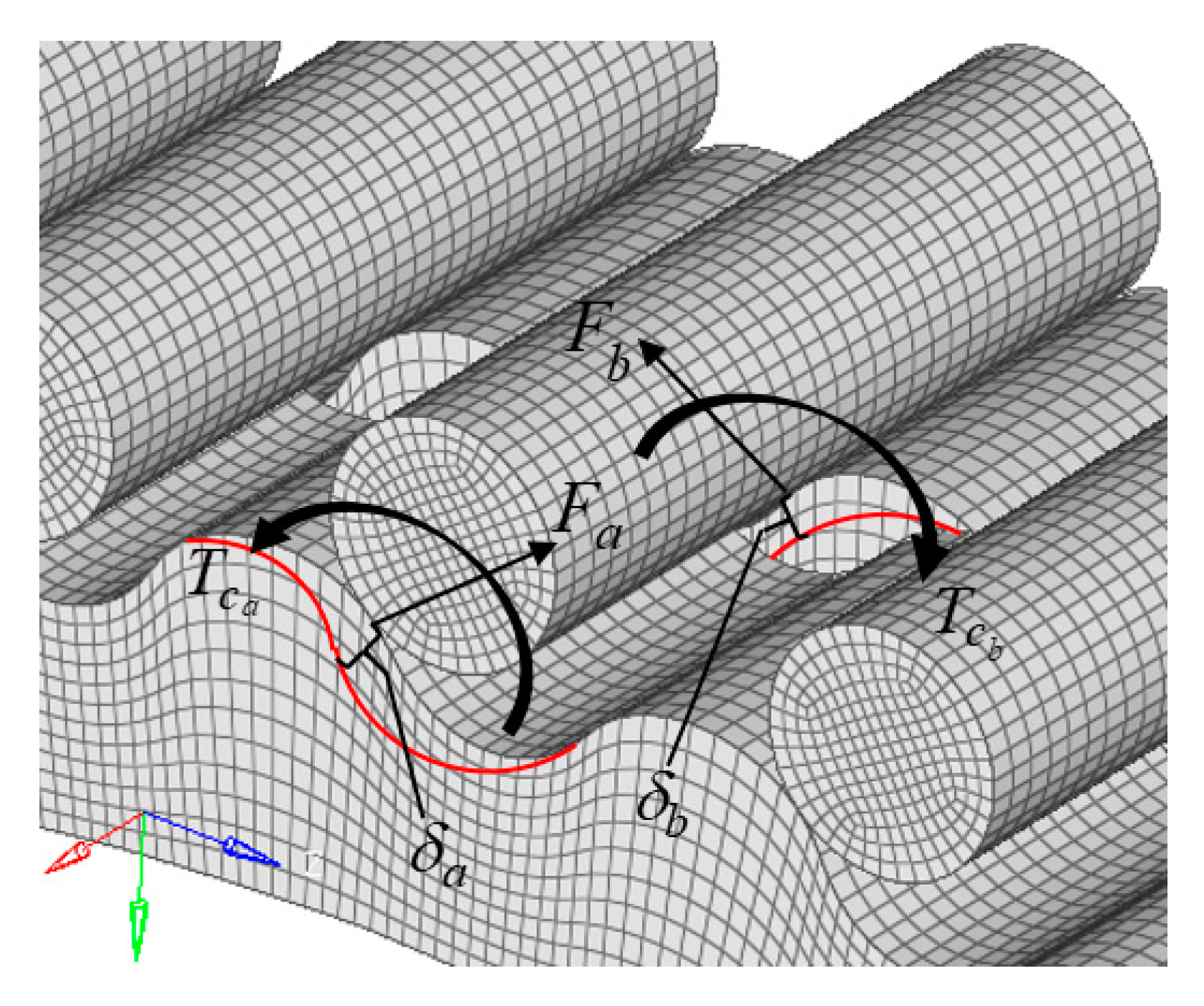
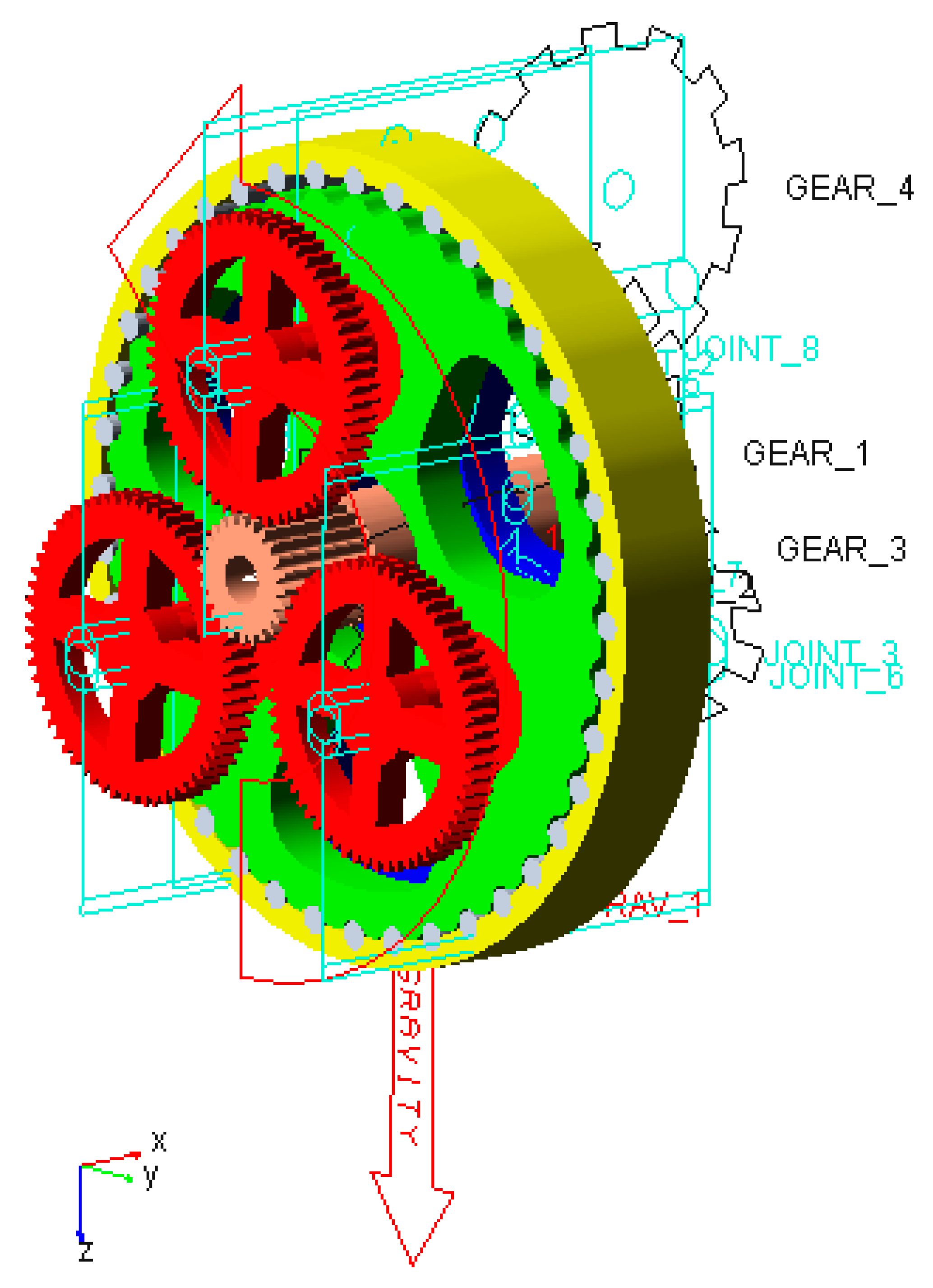
4. Calculation of Contact Forces and Normal Deformation of the Cycloidal Gear and Pinwheels

Normal deformation of the cycloidal gear transmission is the normal displacement of a contact point of the cycloidal gear. Modifications are used to compensate the elastic TE. Modified tooth profiles of the cycloidal gear are not theoretical tooth profiles. The number of pinwheels that simultaneously mesh with the cycloidal gear is less than half the number of teeth of the cycloidal gear. In addition, the initial clearance between different pinwheels and the cycloidal gear is also different. The meshing diagram of the cycloidal gear and pinwheels is shown in Figure 3.

4.1. Calculation of the Meshing Tooth Number and Normal Deformation of the Cycloidal Gear

The position of the maximum contact force of the pinwheel is at the point with the maximum arm of force l max = r c . By excluding small nonlinear deviation caused by the equivalent curvature, the contact force acting on the i -th pinwheel is
F i = l i r c F max .
Assume that pinwheels are fixed in the coordinate system in Figure 3; the torque T c is exerted on the cycloidal gear. Due to normal deformation between the cycloidal gear and pinwheels, the cycloidal gear rotates an angle β . The torque T c is
T c = i = m n F i l i = F max r c i = m n l i 2 = F max r c z p ( i = m n l i 2 r c 2 z p ) = 1 4 F max r c z p .
Based on Equation (29), the maximum contact force between the cycloidal gear and pinwheels is
F max = 4 T c z p r c = 4 T c K 1 z c r p .
Due to the manufacturing error, the torque T transmitted by the RV speed reducer is not equally divided on two cycloidal gears. Equation (29) can be simplified as T c = 0.55 T . Equation (30) can also be written as
F max = 2.2 T K 1 z c r p .
There is no simultaneous meshing of multiple pairs of cycloidal gears and pinwheels after tooth profile modification if normal deformation is not considered. Tooth profile modification leads to an initial normal clearance Δ ( φ ) i in the normal direction between a cycloidal gear and a pinwheel, which can be represented as
Δ ( φ ) i = Δ r r p ( 1 sin φ i 1 + K 1 2 2 K 1 cos φ i ) Δ r r p ( 1 K 1 cos φ i 1 K 1 2 sin φ i ) 1 + K 1 2 2 K 1 cos φ i ,
where φ i is the angle between the i -th pinwheel and arm of force. Let Δ ( φ ) i = 0 ; one has
cos φ i = K 1 ,
φ i = φ 0 = arccos K 1 .
The implication of this result is that the initial normal clearance is zero at this angle. The cycloidal gear and pinwheels begin to mesh at this angle.
When the cycloidal gear transfers the torque T c , contact deformation of the cycloidal gear w and that of the pinwheel f occur. The maximum contact stress of cycloidal gears and pinwheels is obtained by using Abaqus [24,31], as shown in Figure 4. This is a quasi-static simulation. The hexahedral mesh is adopted to divide the model. Pinwheels are fixed and only two cycloidal gears can rotate around the central axis. The torque of the cycloidal gear transmission acts at the geometric center of cycloidal gears. Finite element meshes of the cycloidal gear transmission are shown in Figure 5. The simulation result shows that the maximum magnitude of the contact stress of the cycloidal gear is 1.102 × 10⁴ Pa, while that of the pinwheel is 4.89 × 10⁻²⁶ Pa. The contact deformation of the pinwheel f is produced by its contact stress. Since the maximum magnitude of contact stress of the cycloidal gear is 1030 times that of pinwheels, contact deformation of the pinwheel f is neglected here.
Normal deformation of the contact point with the torque T c can be represented as
δ i = l i β ,
where i = 1 , 2 , , z p / 2 , β is the angle of the cycloidal gear caused by contact deformation, and l i is the distance in the normal direction from the i -th contact point to the center of the cycloidal gear O c that can be represented as
l i = r c cos α i = r c sin φ i 1 + K 1 2 2 K 1 cos φ i ,
in which r c is the radius of the cycloidal gear and α i is the meshing angle of the i -th contact point.
At the contact point with the maximum contact force between the cycloidal gear and pinwheels, Equation (36) can be simplified as l max = r c sin φ 0 1 + K 1 2 2 K 1 cos φ 0 r c . The rotation angle of the contact point with the maximum contact force is φ 0 = arccos K 1 . Substituting l max = r c into Equations (32)–(36) yields
δ i = l i β = l i δ max l max = l i r c δ max = sin φ i 1 + K 1 2 2 K 1 cos φ i δ max ,
where δ max is the maximum normal deformation that can be represented as
δ max = 2 F max ( 1 μ 2 ) π E b ( 2 3 + I n 16 r r p | ρ | c 2 ) ,
in which
c = 4.99 × 10 3 4 ( 1 μ 2 ) F max | ρ | r r p E b ( | ρ | + r r p ) ,
with μ and E being Poisson ratio and the elastic modulus of the cycloidal gear and pinwheels, respectively, and ρ being the curvature radius of tooth profiles of the cycloidal gear at the position φ 0 = arccos K 1 , which can be represented as
ρ = r p ( 1 + K 1 2 2 K 1 cos φ 0 ) 3 2 K 1 ( z p + 1 ) cos φ 0 ( 1 + z p K 1 2 ) + r r p .
If δ i is greater than Δ ( φ ) i , this pair of the cycloidal gear and pinwheel is in the meshing state.

4.2. Calculation of the Number of Meshing Gears and the Contact Force

Since initial clearances Δ ( φ ) i are different after modification of the cycloidal gear, the relationship between F i and δ i = l i β is nonlinear. However, since changes in F i and δ i Δ ( φ ) i are small, the relationship between F i and δ i Δ ( φ ) i is assumed to be linear. Based on the above analysis, pinwheels in the simultaneous meshing state are classified as pinwheels from the m -th to the n -th pinwheel. The contact force of the i -th pinwheel is
F i = δ i Δ ( φ ) i δ max F max ,
where F max is the maximum contact force at the position where the pinwheel is at or close to the position φ i = φ 0 = arccos K 1 . Based on the moment equilibrium equation, T c can be represented as
T c = i = m n F i l i ,
where δ i = l i β and δ max = r c β . Submitting Equation (41) into Equation (42) yields
T c = F max i = m n ( l i r c Δ ( φ ) i δ max ) l i .
Therefore, the maximum contact force F max on the pinwheel with tooth profile modification can be derived as
F max = T c i = m n ( l i r c Δ ( φ ) i δ max ) l i = 0.55 T i = m n ( l i r c Δ ( φ ) i δ max ) l i .
One can calculate F max by giving an initial value of F max that is F max 0 , which can be represented as
F max 0 = 1 2 ( F 1 F 2 ) .
According to Equation (31), F 1 can be represented as
F 1 = 2.2 T z c r p .
By assuming that there is only one pair of cycloidal gear and pinwheel meshing at the position φ i = φ 0 = arccos K 1 with tooth profile modification, F 2 can be represented as
F 2 = 0.55 T r p .
By substituting F max 0 into Equations (37)–(44), the initial value of δ max can be obtained as δ max 0 . Substituting F max 0 and δ max 0 into Equations (37)–(44), one can calculate the number of meshed pinwheels that are from the m -th to the n -th pinwheel. The maximum contact force calculated in each iteration is denoted as F max k . The value of F max 1 at the first iteration is obtained by substituting δ max 0 into Equation (44). By comparing F max 0 with F max 1 , if the absolute value of the difference between F max 0 and F max 1 is greater than 0.1% of F max 1 , it is necessary to calculate δ max 1 by substituting F max 1 into Equations (37)–(44). The second iteration result of F max 2 can be obtained by substituting δ max 1 into Equation (44). The iteration is implemented many times until the result of the k-th iteration F max k satisfies the above condition. Finally, the exact F max can be obtained by
F max = 1 2 ( F max k + F max k 1 ) .
A flowchart of the tooth contact analysis method for cycloidal gear transmissions is shown in Figure 6.

5. Application of the Elastic TE Compensation Method for the RV Speed Reducer

The elastic TE compensation method, which means compensating the elastic TE by modification, is illustrated in this section. The key point of this method is the calculation of the total TE that includes elastic and geometric TEs by using Adams.

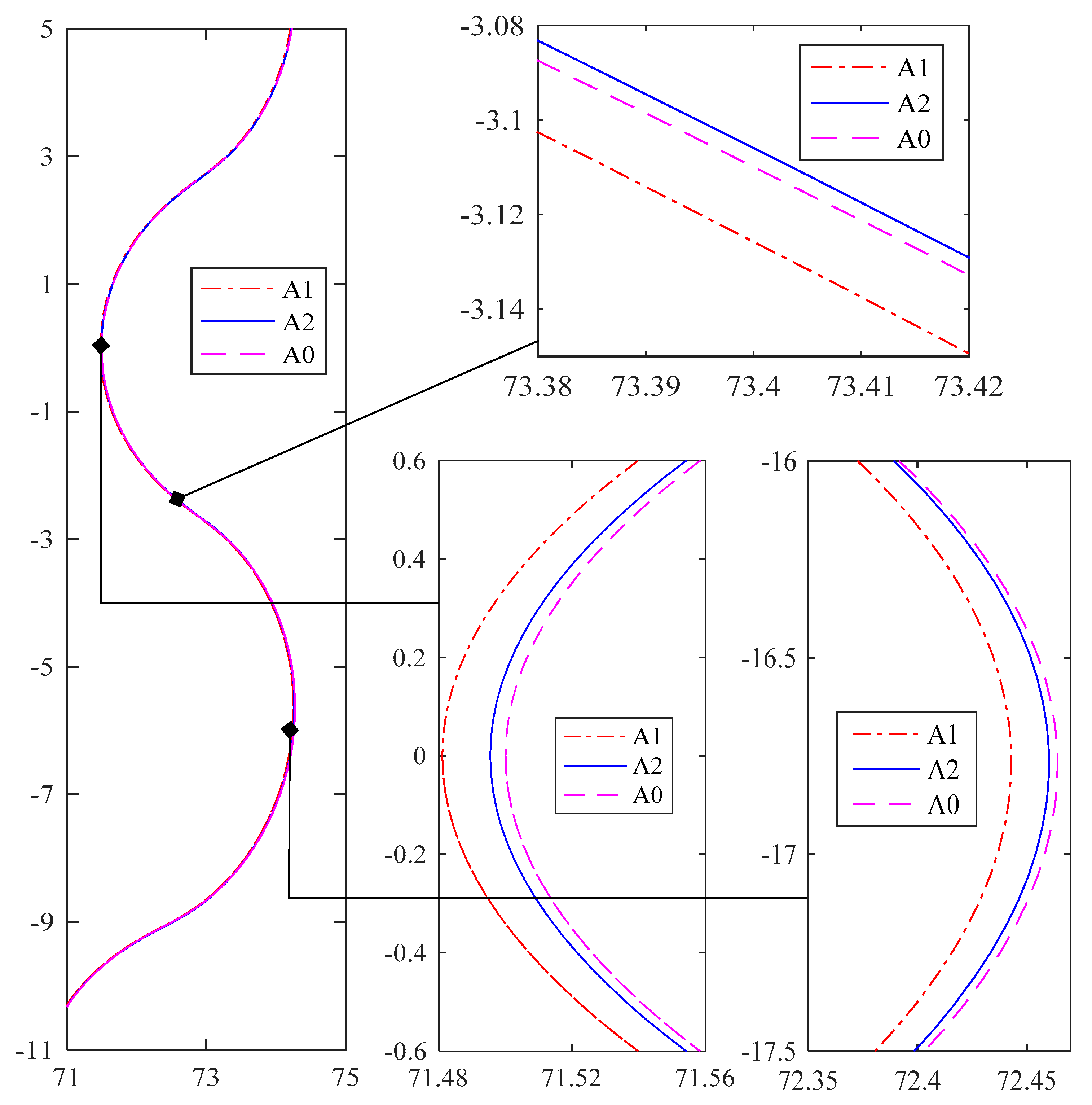
5.1. Modified RV Speed Reducer Prototype Obtained by TE Compensation

An RV speed reducer prototype model is used for numerical analysis of the error sensitivity index. According to the flowchart in Figure 6 and parameters of the initial RV speed reducer prototype in Table 3, initial clearances Δ ( φ ) i and normal deformation δ i of the RV speed reducer prototype before modification are shown in Figure 7. The m -th pinwheel is the first pinwheel in the meshing state and the n -th pinwheel is the last pinwheel in the meshing state. There are nine pinwheels from the m -th to the n -th pinwheel, which are in meshing states with the cycloidal gear before modification of the cycloidal gear. The maximum contact force F max and normal deformation δ i of the initial RV speed reducer prototype before modification can be obtained after 22 iterations, as shown in Table 4 and Table 5. To transfer the torque T c , the maximum contact force F max between a cycloidal gear and a pinwheel of the RV speed reducer prototype before modification is 1910.3 N. The maximum normal deformation δ max of a cycloidal gear before modification is 0.0116 mm.
In order to verify the feasibility and accuracy of the proposed elastic TE compensation method, the TE of the RV speed reducer is simulated by using Adams, as shown in Figure 8. The input angular velocity of the RV speed reducer is set as a sine function V = A sin ( B t ) + C , where A is 4615, B is 30, and C is 2005. The function completes one cycle at a time, the input shaft completes one rotation with a change of the rotation direction, and the TE completes one accumulation. The mean of the TE is smoother, and the change of the rotation direction of the cycloidal gear is smoother. In Adams, cycloidal gears with normal deformation are set as flexible bodies, and the contact penetration value between a cycloidal gear and pinwheels is set as 10−3.
The simulated input shaft rotation angle after running 0.4 s is 826.2965° and the simulated output shaft rotation angle after running 0.4 s is 8.1977°. The total TE of the initial prototype model has accumulated twice after running 0.4 s and its value for a period is 1.4559′. The total TE is divided into TEs that are caused by the pinwheel radius error, the shifting tooth profile modification error, and the cumulative error of the circumference of the cycloidal gear in inverse proportion. By substituting the TEs into Equation (26), the error compensation amount of each TE factor is obtained by Equation (27). The 3D model of the modified RV speed reducer prototype is modified based on modifications for TE compensation of prototype components. The parameters of the modified RV speed reducer prototype are shown in Table 6.

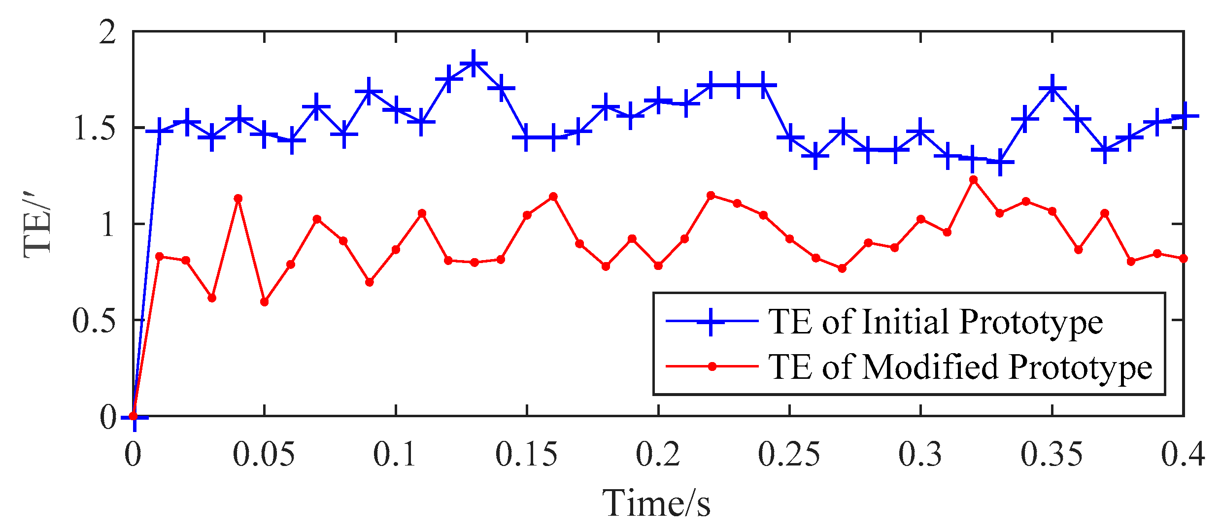
5.2. Validation of the TE Compensation Method and Comparison between the Initial and Modified Prototypes

After TE compensation, the TE of the modified RV speed reducer is simulated by using Adams. The simulated input shaft rotation angle of the modified RV speed reducer prototype model after running 0.4 s is 826.2996°. The simulated output shaft rotation angle of the modified RV speed reducer prototype model after running 0.4 s is 8.2429°. The TE of the modified RV speed reducer prototype model has accumulated twice and its value for a period is 0.8538’. TE simulation results of output shaft rotation angles of the initial and modified RV speed reducer prototype models are shown in Figure 9. By comparing the TE of the modified RV speed reducer prototype model with that of the initial RV speed reducer prototype model, the TE of the modified RV speed reducer prototype model is reduced by 41.35%.
The contact force and deformation of the modified RV speed reducer prototype and those of the initial RV speed reducer prototype are calculated based on the tooth contact analysis method for cycloidal gear transmissions. The maximum contact force F max and normal deformation δ i of the modified RV speed reducer prototype can be obtained after 17 iterations, as shown in Table 7 and Table 8, respectively. To transfer the same torque T c , the maximum contact force F max between a cycloidal gear and a pinwheel of the modified RV speed reducer prototype is 1435.9 N. After TE compensation, the maximum contact force F max of the RV speed reducer prototype is reduced by 24.83%. The maximum normal deformation δ max of the cycloidal gear after modification is 0.0088 mm. After TE compensation, the maximum normal deformation δ max of cycloidal gear of the RV speed reducer is reduced by 24%. The initial clearance Δ ( φ ) i and contact deformation δ i of the modified RV speed reducer prototype are shown in Figure 10. After TE compensation, the number of meshing teeth of the cycloidal gear increases from 9 to 17.
In order to analyze the proportion of the elastic TE in the total TE, a rigid RV speed reducer prototype model is simulated by using Adams. The simulated input shaft rotation angle after running 0.4 s is 826.2977° and the simulated output shaft rotation angle after running 0.4 s is 8.2056°. The TE of the modified RV speed reducer prototype model has accumulated twice after running 0.4 s and its value for a period is 1.22195′. Output shaft rotation angles of the modified RV speed reducer prototype model are shown in Figure 11. By comparing TEs of the initial and modified RV speed reducer prototype models, the elastic TE accounts for 25.28% of the total TE. Hence, simulation results of TEs of the initial and modified RV speed reducer prototype models verify the feasibility of the proposed elastic TE compensation method.
Adams simulation results of the contact force between cycloidal gears and pinwheels of the modified RV speed reducer prototype model are shown in Figure 12. Changes of the contact force can be observed. The simulation result of the maximum contact force F max is 1428 N, which is similar to that of F max of the modified RV speed reducer prototype model. The maximum contact force result of the cycloidal gear that is obtained by the tooth contact analysis method shows acceptable agreement with the Abaqus simulation result.
The TE of the modified RV speed reducer prototype model is obviously reduced. This is due to the decrease of normal deformation δ i and the contact force caused by the increase of meshing gears. Therefore, it can be indicated that the proposed TE compensation method effectively improves the transmission accuracy of RV speed reducers.

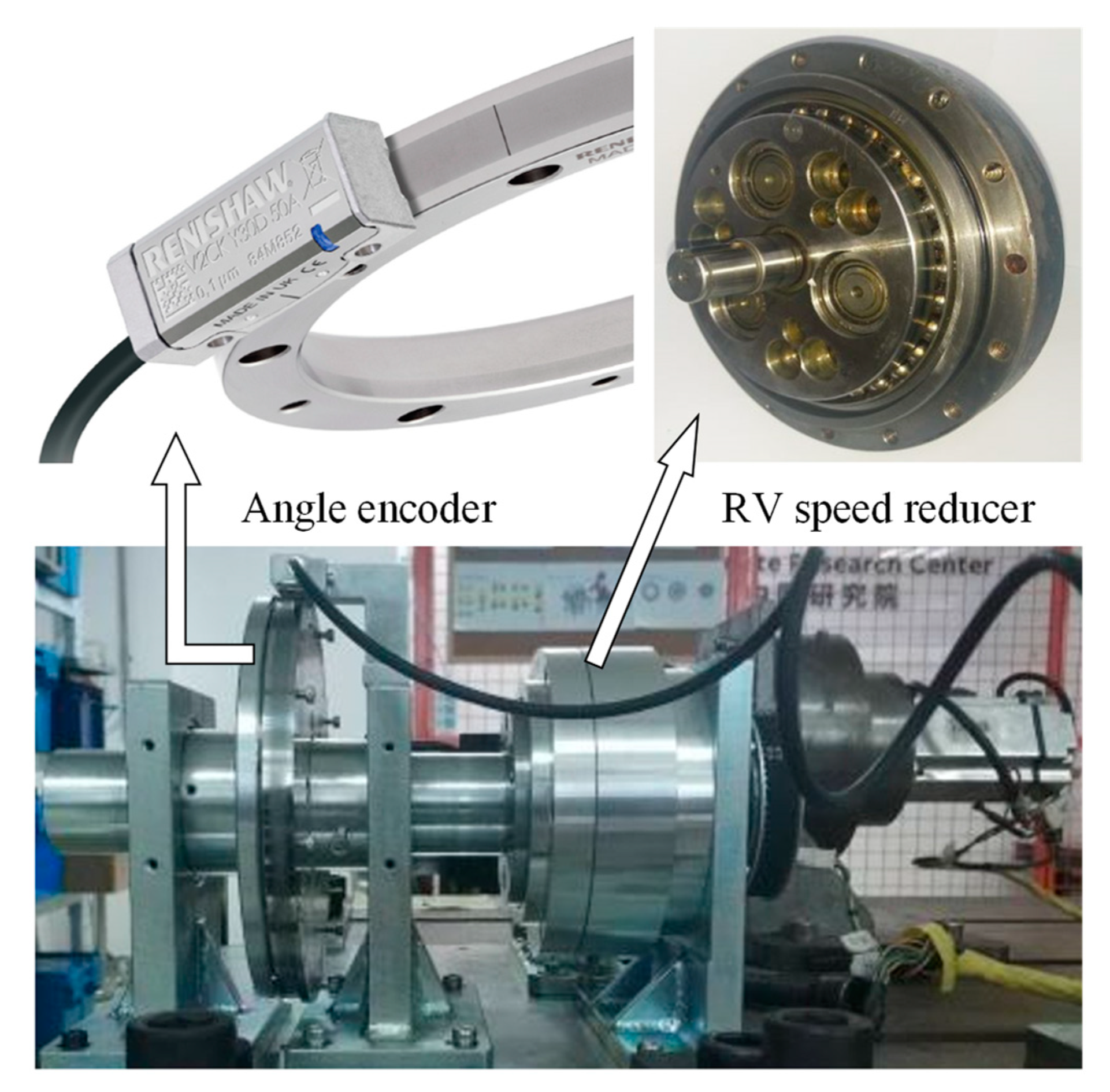
5.3. Meshing Analysis and Experimental Validation

Cycloidal gear specimens a1 and a2 were manufactured by a gear grinding machine based on parameters of the initial and modified RV speed reducer models. Manufacturing errors of cycloidal gears are inevitable. Tooth profiles of cycloidal gear specimens a1 and a2 were measured by using a tooth profile meter. Measurement results with an amplification factor of cycloidal gear specimens a1 and a2 are shown in Figure 13. Curves A0, A1, and A2 are tooth profiles of the theoretical cycloidal gear a0 without any modification, the measurement result of the initial model profile of the cycloidal gear a1 with manufacturing errors, and the measurement result of the modified model profile the cycloidal gear a2 with manufacturing errors and modifications, respectively.
TE tests for RV speed reducers were conducted on a TE test bench, as shown in Figure 14. Equipment types of components in the TE test bench are listed in Table 9. The TE test result of the RV speed reducer with the cycloidal gear specimen a1 was 1.552’ and that of the RV speed reducer with the cycloidal gear specimen a2 was 0.819’, as shown in Figure 15. By comparing the TE test result of the RV speed reducer with the cycloidal gear specimen a2 and that with a1, the TE test result of the modified RV speed reducer prototype was reduced by 47.22%. TE test results showed the effectiveness of the proposed elastic TE compensation method.

6. Conclusions

A geometric TE analysis model is developed to determine error factors with positive effects on the total TE of an RV speed reducer and calculate its sensitivity indices. A TE compensation method for cycloidal gears is proposed based on modification. The maximum contact force and normal deformation of contact points are calculated by the tooth contact analysis method. Total TEs of RV speed reducers with elastic TEs can be compensated by tooth surface modification of cycloidal gears. This process is called the elastic TE compensation method, the feasibility of which is validated by simulation and experimental results. This method can quickly calculate the compensation value of the error of each component for the total TE to improve transmission accuracy, shorten the development cycle, and reduce the manufacturing costs of RV speed reducers. Based on the obtained results, some conclusions can be drawn as follows:
  • The TE of an RV speed reducer can be compensated by error factors of components with positive effects that are determined by the error compensation model.
  • Tooth surface modifications of a cycloidal gear transmission for its TE compensation can be calculated by error sensitivity analysis of the RV speed reducer.
  • Meshing conditions of cycloidal gears and pinwheels of an RV speed reducer can be improved by TE compensation. The maximum contact force, normal deformation, and the meshing tooth number of the cycloidal gear transmission can also be improved.

Author Contributions

Conceptualization, Y.H. and G.L.; methodology, Y.H. and G.L.; software, Y.H.; validation, Y.H. and G.L.; formal analysis, Y.H. and G.L.; investigation, Y.H. and G.L.; data curation, Y.H.; writing—original draft preparation, Y.H.; writing—review and editing, G.L. and W.Z.; visualization, Y.H.; supervision, G.L. and W.Z.; project administration, W.Z. and J.C.; funding acquisition, W.Z. All authors have read and agreed to the published version of the manuscript.

Funding

The authors are grateful for the financial support from the National Science Foundation under Grant No. 1335397, and the National Science Foundation of China under Grant No. 11772100.

Conflicts of Interest

The authors declare no conflict of interest.

References

  1. Zhang, Q.; Kang, J.H.; Dong, W.; Lyu, S.K. A study on tooth modification and radiation noise of a manual transaxle. Int. J. Precis. Eng. Manuf. 2012, 13, 1013–1020. [Google Scholar] [CrossRef]
  2. Li, G.; Wang, Z.H.; Kubo, A. The modeling approach of digital real tooth surfaces of hypoid gears based on non-geometric-feature segmentation and interpolation algorithm. Int. J. Precis. Eng. Manuf. 2016, 17, 281–292. [Google Scholar] [CrossRef]
  3. Fan, Q.R.; Zhou, Q.; Wu, C.Q.; Guo, M. Gear tooth surface damage diagnosis based on analyzing the vibration signal of an individual gear tooth. Adv. Mech. Eng. 2017, 9. [Google Scholar] [CrossRef] [Green Version]
  4. Liu, F.H.; Jiang, H.J.; Zhang, L.; Chen, L. Analysis of vibration characteristic for helical gear under hydrodynamic conditions. Adv. Mech. Eng. 2017, 9. [Google Scholar] [CrossRef] [Green Version]
  5. Li, G.; Wang, Z.H.; Kubo, A. Error-sensitivity analysis for hypoid gears using a real tooth surface contact model. J. Mech. Eng. Sci. 2017, 231, 507–521. [Google Scholar] [CrossRef]
  6. Li, G.; Wang, Z.H.; Zhu, W.D. Prediction of surface wear of involute gears based on a modified fractal method. ASME J. Tribol. 2019, 141, 031603. [Google Scholar] [CrossRef]
  7. Kahraman, A.; Singh, R. Non-linear dynamics of a geared rotor-bearing system with multiple clearances. J. Sound Vib. 1991, 144, 469–506. [Google Scholar] [CrossRef]
  8. Blankenship, G.W.; Kahraman, A. Steady state forced response of a mechanical oscillator with combined parametric excitation and clearance type non-linearity. J. Sound Vib. 1995, 185, 743–765. [Google Scholar] [CrossRef] [Green Version]
  9. Byrtus, M.; Zeman, V. On modeling and vibration of gear drives influenced by nonlinear couplings. Mech. Mach. Theory 2011, 46, 375–397. [Google Scholar] [CrossRef]
  10. Chen, J.S. Vibration reduction in electric bus during acceleration and gear shifting. Adv. Mech. Eng. 2015, 7. [Google Scholar] [CrossRef] [Green Version]
  11. Li, G.; Wang, Z.H.; Zhu, W.D.; Kubo, A. A function-oriented active form-grinding method for cylindrical gears based on error sensitivity. Int. J. Adv. Manuf. Technol. 2017, 92, 3019–3031. [Google Scholar] [CrossRef]
  12. Wang, F.; Xu, X.; Fang, Z.D.; Chen, L. Study of the influence mechanism of pitch deviation on cylindrical helical gear meshing stiffness and vibration noise. Adv. Mech. Eng. 2017, 9. [Google Scholar] [CrossRef]
  13. Wang, F.; Xu, X.; Fang, Z.D.; Chen, L. Design and analysis of herringbone gear with sixth-order transmission error based on meshing vibration optimization. Adv. Mech. Eng. 2017, 9. [Google Scholar] [CrossRef]
  14. Yang, D.C.H.; Blanche, J.G. Design and application guidelines for cycloid drives with machining tolerances. Mech. Mach. Theory 1990, 25, 487–501. [Google Scholar] [CrossRef]
  15. Blanche, J.G.; Yang, D.C.H. Cycloid drives with machining tolerances. J. Mech. Trans. Autom. Des. 1989, 111, 337–344. [Google Scholar] [CrossRef]
  16. Hidaka, T.; Wang, H.; Ishida, T.; Matsumoto, K.; Hashimoto, M. Rotational transmission error of K-H-V planetary gears with cycloid gear: 1st report, analytical method of the rotational transmission error. Trans. JSME Ser. C 1994, 60, 645–653. [Google Scholar] [CrossRef] [Green Version]
  17. Ishida, T.; Wang, H.; Hidaka, T.; Hasataka, H. Rotational transmission error of K-H-V-Type planetary gears with cycloid gears: 2nd report, effects of manufacturing and assembly errors on rotational transmission error. Trans. JSME Ser. C 1994, 60, 3510–3517. [Google Scholar] [CrossRef] [Green Version]
  18. Wang, H.; Ishida, T.; Hidaka, T. Rotational transmission error of K-H-V-Type planetary gears with cycloid gear: 3rd report, mutual effects of errors of the elements on the rotational transmission error. Trans. JSME Ser. C 1994, 60, 3518–3525. [Google Scholar] [CrossRef] [Green Version]
  19. Yu, H.L.; Yi, J.H.; Xin, H.; Shi, P. Study on teeth profile modification of cycloid reducer based on non-hertz elastic contact analysis. Mech. Res. Commun. 2013, 48, 87–92. [Google Scholar] [CrossRef]
  20. Li, X.; Li, C.Y.; Wang, Y.W.; Chen, B.K.; Lim, T.C. Analysis of a cycloid speed reducer considering tooth profile modification and clearance-fit output mechanism. J. Mech. Des. 2017, 139, 033303. [Google Scholar] [CrossRef]
  21. Ambarisha, V.K.; Parker, R.G. Nonlinear dynamics of planetary gears using analytical and finite element models. J. Sound Vib. 2007, 302, 577–595. [Google Scholar] [CrossRef]
  22. Yi, P.X.; Zhang, C.; Guo, L.J.; Shi, T.L. Dynamic modeling and analysis of load sharing characteristics of wind turbine gearbox. Adv. Mech. Eng. 2015, 7. [Google Scholar] [CrossRef]
  23. Lai, T.S. Design and machining of the epicycloid planet gear of cycloid drives. Int. J. Adv. Manuf. Technol. 2006, 28, 665–670. [Google Scholar] [CrossRef]
  24. Blagojevic, M.; Marjanovic, N.; Djordjevic, Z.; Stojanovic, B.; Disic, A. A new design of a two-stage cycloidal speed reducer. ASME J. Mech. Des. 2011, 133, 085001. [Google Scholar] [CrossRef]
  25. Park, J.H.; Jeon, B.J.; Park, J.M.; Kim, M.Y.; Youn, B.D. Failure prediction of a motor-driven gearbox in a pulverizer under external noise and disturbance. Smart Struct. Syst. 2018, 22, 185–192. [Google Scholar] [CrossRef]
  26. Hwang, Y.W.; Hsieh, C.F. Geometric design using hypotrochoid and nonundercutting conditions for an internal cycloidal gear. ASME J. Mech. Des. 2007, 129, 413–420. [Google Scholar] [CrossRef]
  27. Mertens, A.J.; Senthilvelan, S. Durability of polymer gear-paired with steel gear manufactured by wire cut electric discharge machining and hobbing. Int. J. Precis. Eng. Manuf. 2016, 17, 181–188. [Google Scholar] [CrossRef]
  28. Hsieh, C.F. Dynamics analysis of cycloidal speed reducers with pinwheel and nonpinwheel designs. ASME J. Mech. Des. 2014, 136, 091008. [Google Scholar] [CrossRef]
  29. Qin, D.; Wang, J.; Lim, T.C. Flexible multibody dynamic modeling of a horizontal wind turbine drivetrain system. ASME J. Mech. Des. 2009, 131, 114501. [Google Scholar] [CrossRef]
  30. Li, G.; Zhu, W.D. An active ease-off topography modification approach for hypoid pinions based on a modified error sensitivity analysis method. ASME J. Mech. Des. 2019, 141, 093302. [Google Scholar] [CrossRef]
  31. Qu, W.T.; Peng, X.Q.; Zhao, N.; Hui, G. Finite element generalized tooth contact analysis of double circular arc helical gears. Struct. Eng. Mech. 2012, 43, 439–448. [Google Scholar] [CrossRef]
Figure 1. Structure of an E-series rotary vector (RV) speed reducer.
Applsci 10 00481 g001
Figure 2. Coordinate systems of the cycloidal gear and pinwheel.
Applsci 10 00481 g002
Figure 3. Meshing diagram of the cycloidal gear and pinwheels.
Applsci 10 00481 g003
Figure 4. Stress diagram of cycloidal gears.
Applsci 10 00481 g004
Figure 5. Finite element meshes of the cycloidal gear transmission.
Applsci 10 00481 g005
Figure 6. Flowchart of the tooth contact analysis method for cycloidal gear transmissions.
Applsci 10 00481 g006
Figure 7. Initial clearances and normal deformation of the initial RV speed reducer prototype.
Applsci 10 00481 g007
Figure 8. RV speed reducer prototype model with constraint settings in Adams.
Applsci 10 00481 g008
Figure 9. Output shaft rotation angle of the initial and modified RV speed reducer prototype models.
Applsci 10 00481 g009
Figure 10. Initial clearances and normal deformation of the modified RV speed reducer prototype.
Applsci 10 00481 g010
Figure 11. Output shaft rotation angles of the initial and modified RV speed reducer prototype models.
Applsci 10 00481 g011
Figure 12. Contact force between cycloidal gears and pinwheels.
Applsci 10 00481 g012
Figure 13. Tooth profiles (A0, A1, and A2) of the theoretical cycloidal gear a0 and cycloidal gear specimens a1 and a2.
Applsci 10 00481 g013
Figure 14. TE test bench for RV speed reducers.
Applsci 10 00481 g014
Figure 15. Experimental results of TEs for the initial and modified RV speed reducer prototypes.
Applsci 10 00481 g015
Table 1. Main factors of the geometric transmission error (TE).
Geometric TE θ j θ a θ b θ c θ d θ e θ f θ g θ h θ i
Main factors δ j Δ r r p Δ r p δ r p δ r r p δ j F r 1 δ t Σ Δ F p δ Δ r r p and δ Δ r p
Table 2. Error coefficients and sensitivity indices of error factors.
Error FactorError CoefficientSensitivity Index
Pinwheel center circle radius error δ a 1 Κ 1 2 1
Pinwheel housing radius error δ b −1−1.6308
Pinwheel groove matching clearance δ c 0.50.8154
Cycloidal gear ring radial runout δ d 0.250.4077
Pinwheel housing circumferential position error δ e Κ 1 1.2882
Isometric tooth profile modification error δ f 11.6308
Shifting tooth profile modification error δ g 1 Κ 1 2 −1
Cumulative error of circumference δ h Κ 1 / 2 −0.6441
Eccentricity error δ i k n −0.00024
Table 3. Parameters of the initial rotary vector (RV) speed reducer prototype.
ParameterValue
Pinwheel center circle radius rp/mm76
Pinwheel radius rrp/mm3
Cycloid tooth number zc39
Number of pinwheel teeth zp40
Number of center teeth z122
Number of planetary gear teeth z260
Eccentricity a/mm1.5
Isometric tooth profile modification Δrrp/mm−0.022
Shifting tooth profile modification Δrp/mm−0.0437
Short-formed coefficient Κ 1 0.78993
Table 4. Maximum contact force F max of the initial RV speed reducer prototype.
k δ max k   ( mm ) F max k / N | F max k F max ( k 1 ) | / N 0.1 %   F max k / N
10.03031320.3−1224.802.5451
20.01521657.3336.981.3203
30.00812464.7807.361.6573
40.01012121.5−343.112.4647
190.01151914.25.251.9089
200.01161911.7−2.421.9142
210.01161909.0−2.711.9117
220.01161910.31.251.9090
Table 5. Normal deformation δ i of meshing gears before modification.
i 34567891011
δ i / mm 0.01030.01130.01160.01150.01120.01080.01030.00970.0091
Table 6. Parameters of the modified RV speed reducer prototype.
ParameterValue
Pinwheel center circle radius rp/mm76
Pinwheel radius rrp/mm2.9721
Number of teeth of cycloidal gear zc39
Number of pinwheels zp40
Number of center teeth z122
Number of teeth of planetary gear z260
Eccentricity a/mm1.5
Isometric tooth profile modification Δrrp/mm−0.022
Shifting tooth profile modification Δrp/mm−0.0266
Short-formed coefficient Κ 1 0.7898
Modifications of cumulative error of circumference Δδ8−0.011
Table 7. Maximum contact force F max of the modified RV speed reducer prototype.
k δ max k / mm F max k / N | F max k F max ( k 1 ) | / N 0.1 %   F max k / N
10.03031068.4−177.701.2461
20.00771512.0443.551.0684
30.00661612.3100.351.5120
40.00921403.5−208.831.6123
140.00881437.48.971.4284
150.00871439.92.501.4374
160.00881436.8−3.111.4399
170.00881435.9−0.861.4368
Table 8. Normal deformation δ i of the modified RV speed reducer prototype.
i 2345678910
δ i / mm 0.00780.00860.00880.00880.00860.00830.00790.00740.0069
i 111213\3334353637
δ i / mm 0.00640.00580.0051\−0.0086−0.0088−0.0088−0.0086−0.0078
Table 9. Equipment types of components in the TE test bench.
EquipmentCompanyModelAccuracySampling FrequencyRated SpeedRated Load
Angle encoderRenishawRESM±0.38250 Hz\\
MotorZhongchuangZC80SA\100 HZ3000 rpm9.5 KW
RV speed reducerNabtescoRV-80E-101\\\3.26 KW

