Article

A Multi-Degree of Freedom Tuned Mass Damper Design for Vibration Mitigation of a Suspension Bridge

1
China Electric Power Research Institute, Beijing 100055, China
2
Robotics Institute, Beihang University, Beijing 100191, China
3
Active Structures Laboratory, Université Libre de Bruxelles, 1050 Brussels, Belgium
*
Authors to whom correspondence should be addressed.
Appl. Sci. 2020, 10(2), 457; https://doi.org/10.3390/app10020457
Submission received: 12 November 2019 / Revised: 15 December 2019 / Accepted: 31 December 2019 / Published: 8 January 2020

Abstract

:
This paper proposes a synthetic approach to design and implement a two-degree of freedom tuned mass damper (2DOFs TMD), aimed at damping bending and torsional modes of bridge decks (it can also be applied to other types of bridges like cable-stayed bridges to realize the energy dissipation). For verifying the effectiveness of the concept model, we cast the parameter optimization of the 2DOFs TMDs conceptual model as a control problem with decentralized static output feedback for minimizing the response of the bridge deck. For designing the expected modes of the 2DOFs TMDs, the graphical approach was introduced to arrange flexible beams properly according to the exact constraints. Based on the optimized frequency ratios, the dimensions of 2DOF TMDs are determined by the compliance matrix method. Finally, the mitigation effect was illustrated and verified by an experimental test on the suspension bridge mock-up. The results showed that the 2DOFs TMD is an effective structural response mitigation device used to mitigate the response of suspension bridges. It was also observed that based on the proposed synthetic approach, 2DOFs TMD parameters can be effectively designed to realize the target modes control.

1. Introduction

With the tendency to use longer spans, the damping of modern suspension bridges is seriously reduced. Complex vibration problems follow, such as wind-induced vibration, human-induced vibration, cable-structure interactions and flutter instabilities [1,2,3,4]. It is admitted that the oversensitivity to dynamic excitation of suspension bridges is associated with the very low structural damping in the global bridge modes [5,6]. Therefore, the dissipation of the vibration energy generated by the dynamic loadings is a central issue in their design. At present, the use of damping systems such as tuned mass damper (TMD) [7], viscous dampers [8,9], or active tendon control [10] is a classical way to alleviate the vibrations in structures. This study aims at the design of multi-degree of freedom TMD for vibration damping of a suspension bridge deck.
Considering their simplicity and effectiveness, tuned mass dampers have been widely used in bridges such as the London Millenium bridge, for damping both lateral and vertical vibrations of the deck. Since Frahm et al. proposed the fundamental theory, TMDs have seen numerous applications in civil engineering [11,12,13]. Thus, Ben Mekki and Bourquin [14,15] proposed a new semi-active electromagnetic TMD of pendulum type to damp the torsional mode of an evolving bridge mock-up. Their studies showed that the tuned pendulum damper (TPD) is very effective in vibration damping, qualitatively and quantitatively confirming the theoretical predictions. However, the TMDs can only control single mode and easy detune, which limits their further development. For the robustness of vibration control and targeting several vibration modes, the multiple tuned mass dampers (MTMDs) has been proposed, and its performance is more effective as compared to the single TMD. The superior effectiveness of the MTMDs is able to control almost any type of vibration in civil structures [16]. The MTMDs is used to damp suspension bridges for several purposes. In some studies, the MTMDs are used to the suppression of buffeting, flutter or increasing the critical flutter wind speed [17,18]. Other studies consider MTMDs for alleviating pedestrian- and jogger-induced vibration [19,20,21,22] or traffic-induced vibration [23,24,25,26].
Generally, the weight of a TMD is limited to 1–3% of the structure weight. Hence, as the number of targeted modes increases, a large number of TMDs will increase the burden on the primary system and limit the damping performance (called weight penalty). To avoid such a penalty, in our previous study [27], we proposed to design a two-degree of freedom TMD, where the original mass of TMD is redistributed in such a way that the TMD has a bending mode and a torsional mode. In this design the resonance frequencies and the modal damping of the two modes can be tuned independently. In addition, Zuo and Nayfeh have proposed a multiple degrees of freedom TMD (MDOFs TMD), and experimentally demonstrated that the MDOFs TMD can damp six modes of the primary structure. They also showed that a MDOFs TMD can be used to attain better vibration suppression for single mode vibration of a primary structure [28]. Jang et al. described a novel method for selecting the parameters of a 2DOFs TMD with translational and rotational degrees of freedom [29]. Ma and Yang et al. presented a design of a multi-DOFs TMD to alleviate the dominant mode of the work piece/fixture assembly in milling [30,31,32].
As the DOF increases, by only selecting the appropriate DOFs and tuned frequencies, the TMDs can reach the best vibration control of the primary structure. Therefore, designing a TMD with expected DOFs and natural frequencies becomes an urgent problem. Unfortunately, due to its complicated structure and easily detuning, the further study on the implementation of MDOFs TMD is rare.
In this paper, we propose a synthetic approach based on both the graphical approach and parameterized compliance for the concrete design of the TMDs with the expected DOFs and we verify their feasibility and performance by numerically and experimentally way on a laboratory suspension bridge mock-up. The paper is organized as follows: Section 2 describes the vibration characteristics of the bridge mock-up and builds a concept model of bridge with two 2DOFs TMDs. Based on the equations of motion, the decentralized control technique is directly used to optimize the stiffness and damping coefficients of the springs and dampers to obtain the optimum frequency ratios in Section 3. Section 4 presents the detailed design process of the 2DOFs TMDs based on the graphical approach and compliance analysis. Section 5 mainly focuses on evaluating the damping performance and verifying the proposed design method. Finally, findings and conclusions of the study are summarized at the end.

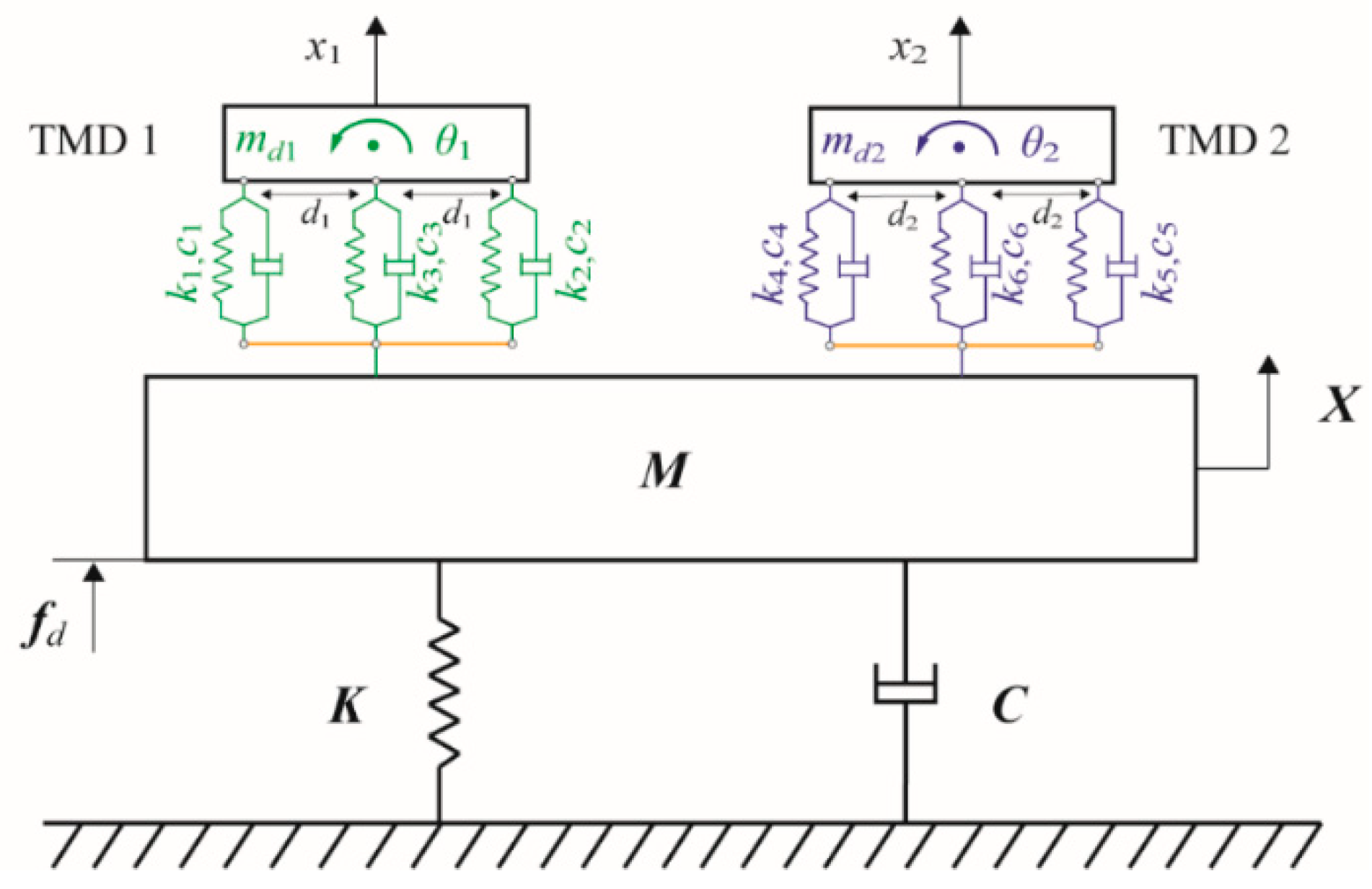
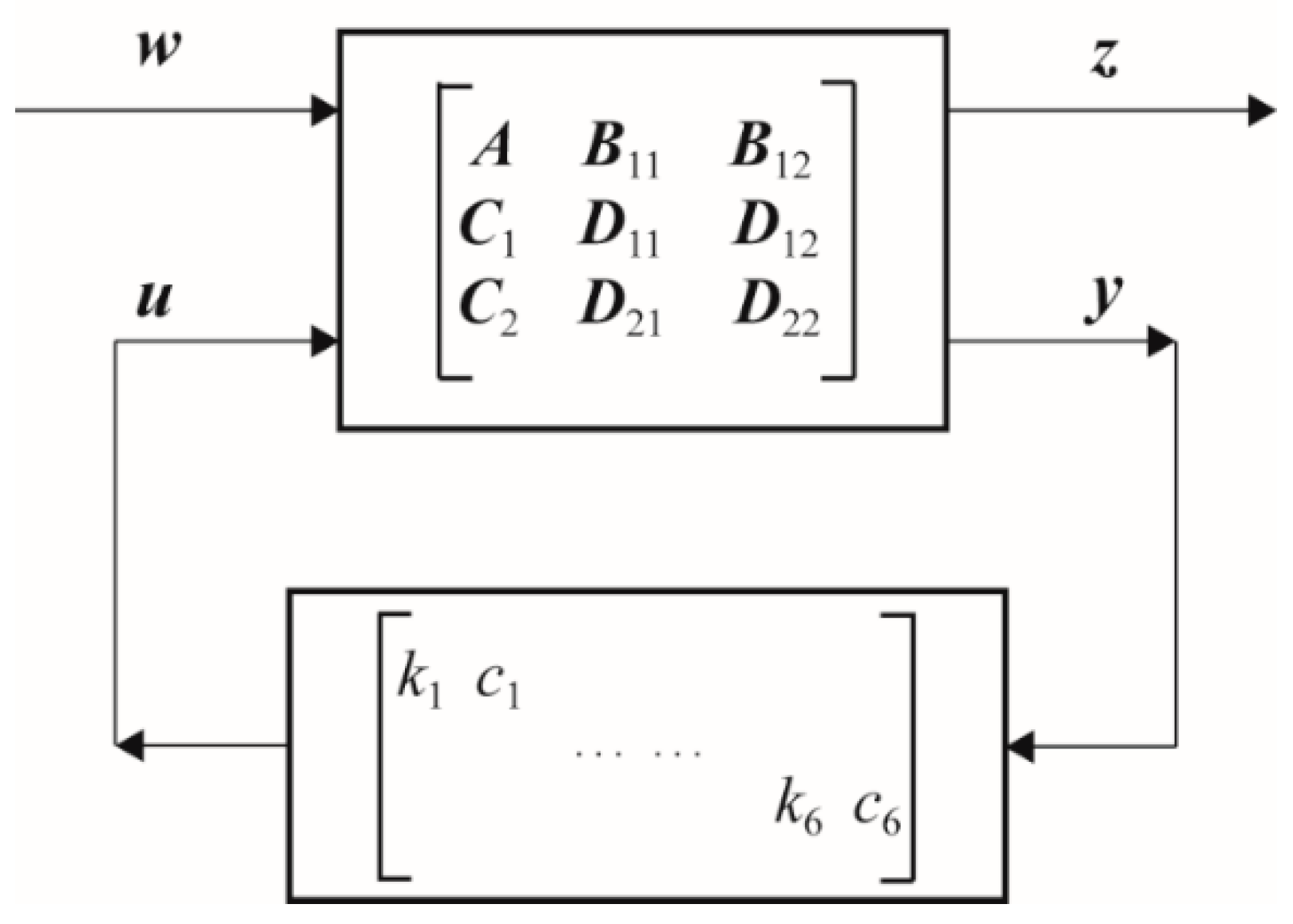
2. Formulation of the Bridge–TMD System

Our goal is to use two 2DOFs TMDs to control the first four vibration modes of the suspension bridge simultaneously. The 2DOFs TMD is decoupled in the physical coordinates, their mode shapes follow the physical coordinate of the mock-up, and the corresponding resonance frequencies can be tuned independently to match the desired design. The suspension bridge mock-up and its finite element modelling are detailed described in our previous studies [27,33,34]. Here, this paper only lists the vibration characteristics of the bridge mock-up, as shown in Table 1.
Since the tuning TMDs becomes increasingly complex, we cast the parameter optimization of the 2DOFs TMDs as a control problem with decentralized static output feedback for minimizing the response of the bridge system. This method has been used successfully for a single mode vibration control of a MDOFs TMD by Zuo and Nayfeh [28]. The concept model of the 2DOFs TMDs is to take the springs as local feedback elements of relative displacements and the dampers as local feedback elements of relative velocities, as shown in Figure 1.
In this way, the role of the springs and dampers can be replaced by a control force vector, where the control gain is composed of the spring stiffness and damping coefficients (ki and ci for i = 1, 2, …, 6). The mass matrix Mn×n, stiffness matrix Kn×n and viscous damping matrix Cn×n is extracted from the numerical model of the suspension bridge mock up, respectively. The 2DOFs TMD has two planar degrees of freedom, translation x1 (x2) and rotation θ1 (θ2). Its mass is md1 (md2) and the rotational inertia about its center of mass is Id = mdρ2, where ρ is the radius of gyration.
The 2DOFs TMD is connected to the primary system at distances d1 (d2) from its center of mass via dashpots and springs. Therefore, the control force vector [u1, u2, …, u6] in this case are given by:
u 1 = k 1 ( x 1 B 2 T X θ 1 d 1 ) + c 1 ( x ˙ 1 B 2 T X ˙ θ ˙ 1 d 1 ) ,
u 2 = k 2 ( x 1 B 2 T X + θ 1 d 1 ) + c 2 ( x ˙ 1 B 2 T X ˙ + θ ˙ 1 d 1 ) ,
u 3 = k 3 ( x 1 B 2 T X ) + c 3 ( x ˙ 1 B 2 T X ˙ ) ,
u 4 = k 4 ( x 2 B 3 T X θ 2 d 2 ) + c 4 ( x ˙ 2 B 3 T X ˙ θ ˙ 2 d 2 ) ,
u 5 = k 5 ( x 2 B 3 T X + θ 2 d 2 ) + c 5 ( x ˙ 2 B 3 T X ˙ + θ ˙ 2 d 2 ) ,
u 2 = k 2 ( x 1 B 2 T X + θ 1 d 1 ) + c 2 ( x ˙ 1 B 2 T X ˙ + θ ˙ 1 d 1 ) ,
where X is the vector of global coordinates of the finite element model, B2 and B3 are the input vector of this two TMDs, respectively.
The equations can govern the vibration of the coupled system can be decomposed into:
m d 1 x ¨ 1 = u 1 u 2 u 3 ,
m d 2 x ¨ 2 = u 4 u 5 u 6 ,
I d 1 θ ¨ 1 = u 1 d 1 u 2 d 1 ,
I d 2 θ ¨ 2 = u 4 d 2 u 5 d 2 ,
The governing equations can then be written as
M X ¨ + C X ˙ + KX = B 1 f d + B 2 ( u 1 + u 2 + u 3 ) + B 3 ( u 4 + u 5 + u 6 ) ,
where fd is the external disturbances, B1 is the input vector of the external disturbances. We can express Equations (7)–(11) in matrix form as:
[ M 0 0 0 0 0 m d 1 0 0 0 0 0 m d 2 0 0 0 0 0 I d 1 0 0 0 0 0 I d 2 ] ( X ¨ x ¨ 1 x ¨ 2 θ ¨ 1 θ ¨ 2 ) + [ C 0 0 0 0 0 0 0 0 0 0 0 0 0 0 0 0 0 0 0 0 0 0 0 0 ] ( X ˙ x ˙ 1 x ˙ 2 θ ˙ 1 θ ˙ 2 ) + [ K 0 0 0 0 0 0 0 0 0 0 0 0 0 0 0 0 0 0 0 0 0 0 0 0 ] ( X x 1 x 2 θ 1 θ 2 ) = ( B 1 0 0 0 0 ) f d + [ B 2 B 2 B 2 B 3 B 3 B 3 1 1 1 0 0 0 0 0 0 1 1 1 d 1 d 1 0 0 0 0 0 0 0 d 2 d 2 0 ] ( u 1 u 2 u 3 u 4 u 5 u 6 ) ,
or
M p p ¨ + C p p ˙ + K p p = B f f d + B u u ,
where p = [X, x1, x2, θ1, θ2]T and u = [u1, u2, …, u6] and T denote the complex conjugate matrix transpose. The matrices Mp, Cp, Kp, Bf, and Bu can be obtained from Equation (12) directly.
Defining the state variables of the system as:
x = [ p p ˙ ] ,
The governing equations are written in first-order form as:
x ˙ = Ax + B 11 w + B 12 u ,
where w = fd and:
A = [ 0 I M p 1 K p ] , B 11 = [ 0 M p 1 B f ] , B 12 = [ 0 M p 1 B u ] ,
The cost output can be taken as the absolute or relative displacement, velocity, or acceleration of the primary system, which can be expressed in the form:
z = C 1 x + D 11 w + D 12 u ,
For the displacement response of the primary system, the cost output can be written as:
z = X = C 1 x ,
where:
C 1 = [ I n × n O n × 4 O n × n O n × 4 ] ,
To complete the state-space description, we rewrite the control force given by Equations (1)–(6) as a static feedback gain F multiplied by the “measurement output” y:
u = Fy = [ k 1 c 1 k 2 c 2 k 6 c 6 ] y ,
where y is given by:
y = [ x 1 B 2 T X θ 1 d 1 , x ˙ 1 B 2 T X ˙ θ ˙ 1 d 1 , x 1 B 2 T X + θ 1 d 1 , x ˙ 1 B 2 T X ˙ + θ ˙ 1 d 1 , x 1 B 2 T X , x ˙ 1 B 2 T X ˙ , x 2 B 3 T X θ 2 d 2 , x ˙ 2 B 3 T X ˙ θ ˙ 2 d 2 , x 2 B 3 T X + θ 2 d 2 , x ˙ 2 B 3 T X ˙ + θ ˙ 2 d 2 , x 2 B 3 T X , x ˙ 2 B 3 T X ˙ ] T = C 2 x + D 21 w + D 22 u ,
where C2 can be obtained from the definition of the state given by Equation (14) and the matrices D21 = 0 and D22 = 0. Equations (15), (17), and (21) cast the design of the two 2DOFs TMDs system as a decentralized control problem in the block diagram of Figure 2.

3. Numerical Optimization and Simulation

According to above equations, the decentralized control techniques can be directly used to optimize the damping and stiffness coefficients of the dampers and springs to achieve performance (measured by z) under the disturbance w. The minimax numerical method [28] is utilized to minimize the response magnitude of the primary system.

3.1. Optimization Criteria

Traditionally, based on the Den Hartog method, the optimized frequency ratio and TMD damping ratio are aimed to minimize the structural response by the minimization of the structural dynamic magnification function. This classic procedure consists of two separate steps: tuning of the frequency of the damper, and selection of the optimal level of the TMD damping ratio. This classic procedure has been used in our previous research [27]. The goal of this study is to design the parameters (ki and ci for i = 1, 2, …, 6) in order to determine the optimum frequency ratio νj (j = 1, …, 4) and the optimum TMD damping ratio ξj for minimizing the response of the bridge system.
Due to the fact that the maximum amplitude of the bridge system should be controlled in a reasonable range, herein the damping performance of TMDs is evaluated by the H criterion. H is the selected FRF value of the bridge system under the excitation fd. The value range of Hj is constrained by the value range of ωj (ωj ϵ [0.7ωsj,1.3ωsj]). The goal of the optimization is to minimize the maximum value of each value range of Hj. χ = [k1, c2, …, k6, c6]T is selected as the design parameter vector of the TMDs. The optimization problem can be written as:
Find : χ = [ k 1 , c 1 , k 2 , c 2 , k 3 , c 3 , k 4 , c 4 , k 5 , c 5 , k 6 , c 6 ] T Minimize : j = 1 4 W j ( max | H j ( χ , ω j ) | ) Subject   to : I = { j | 0.7 ω s j ω j 1.3 ω s j , ω j = | e i g ( A + B 12 F C 2 ) | }
where j (j = 1, …, 4) is the mode number considered and ωsj is the j-th natural frequency of the primary system. ωj is the evaluation of the eigenvalues, which corresponding to the modal frequencies of the entire system inside the specified frequency band. Wj = 0.25, which is the weight coefficient. For each TMD, 2% of the total mass of the structure.

3.2. Numerical Optimization Results

Two TMD devices are used to damp the mode pairs (1B,2T) and (2B,1T); one TMD is placed at the quarter length of the deck (TMD1), the second is located at the center of the deck (TMD2). A detailed description is shown in Section 4.2. A disturbance force fd is applied at one fixed point of the deck edge and the displacement z is measured at another fixed point, as shown in a small graph of Figure 3. According to Equation (22), the frequency response functions of the primary system with two 2DOFs TMDs are optimized, and the optimum frequency ratios and TMD damping ratios are obtained, as listed in Table 2.
Figure 3 shows the frequency responses of the deck z/fd, when: (i) without any TMD; (ii) the four classical TMDs are targeting to damp the two mode pairs (2B,1T) and (1B,2T), which is achieved by Den Hartog criterion; and (iii) the two 2DOFs TMDs are targeting to damp the two mode pairs (2B,1T) and (1B,2T), which is optimized by that introduced in the present paper. The results indicate that the 2DOFs TMD concept model is effective to suppress both the bending modes and torsional modes of the bridge system at the same time. But, if using the classical configuration of the TMD, we need four TMDs, each of them is tuned on a single mode at the same time: two translation TMDs, with a lumped mass identical to that used in the 2DOFs TMD, and two other TMDs with moment of inertia identical to that of the 2DOFs TMD too. Hence, comparing with the classical configuration of TMD, the two 2DOFs TMDs can reduce the weight penalty.
Figure 4 shows the FRF for different sensor locations, with the same TMD design as in Figure 3. This figure demonstrates the robustness with respect to the FRF used in the TMD design. Figure 5 plots the frequency response curve of the bridge equipped with TMD1, for different values of the TMD1 damping ratio ξ. Here, the TMD1 damping ratio ξ is selected as 10% ξopt, 25% ξopt, 50% ξopt and ξopt, respectively, and the ξopt is the optimum damping ratio of TMD1, which is listed in Table 2. From this figure, we see that the dynamic responses of the bridge deck always tend to decrease on increasing the damping ratio of TMD1. Furthermore, the frequency ratio is insensitive to the TMD damping ratio, but if the action is not perfectly resonant, the performance of TMD may decay seriously even though the value of the TMD damping ratio is very high [35]. For TMD structure design, unlike the damping ratio ξj which is difficult to quantify, the frequency ratio νj is important parameter which can be used to guide the following TMD structural parameters design.

4. Structural Design of 2DOFs TMD

Due to the lack of an effective theoretical guidance, deterministic structure design of multi-DOFs TMDs is still a challenge in the field of TMD design. The main problems are: (1) kinematic constraints design of the multi-DOFs, it ensures that the TMDs have the expected DOFs; and (2) parametric modeling of the multi-DOFs, that contributes to design the TMD and ensure it has the expected natural frequencies. To solve the above problems, this study presents a synthetic approach based on both the graphical approach [36] and parameterized compliance for the concrete design of the TMD with the expected DOFs.

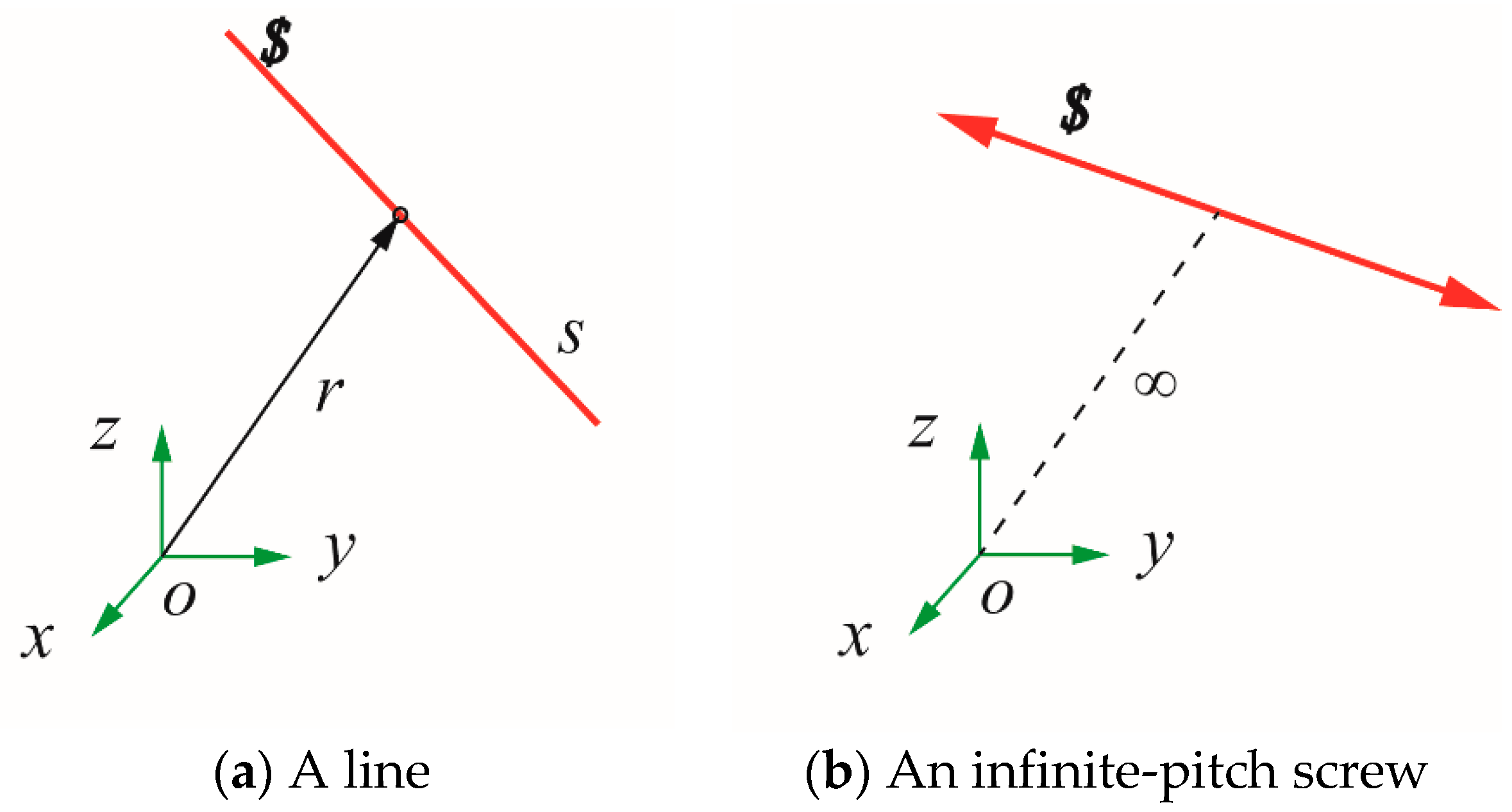
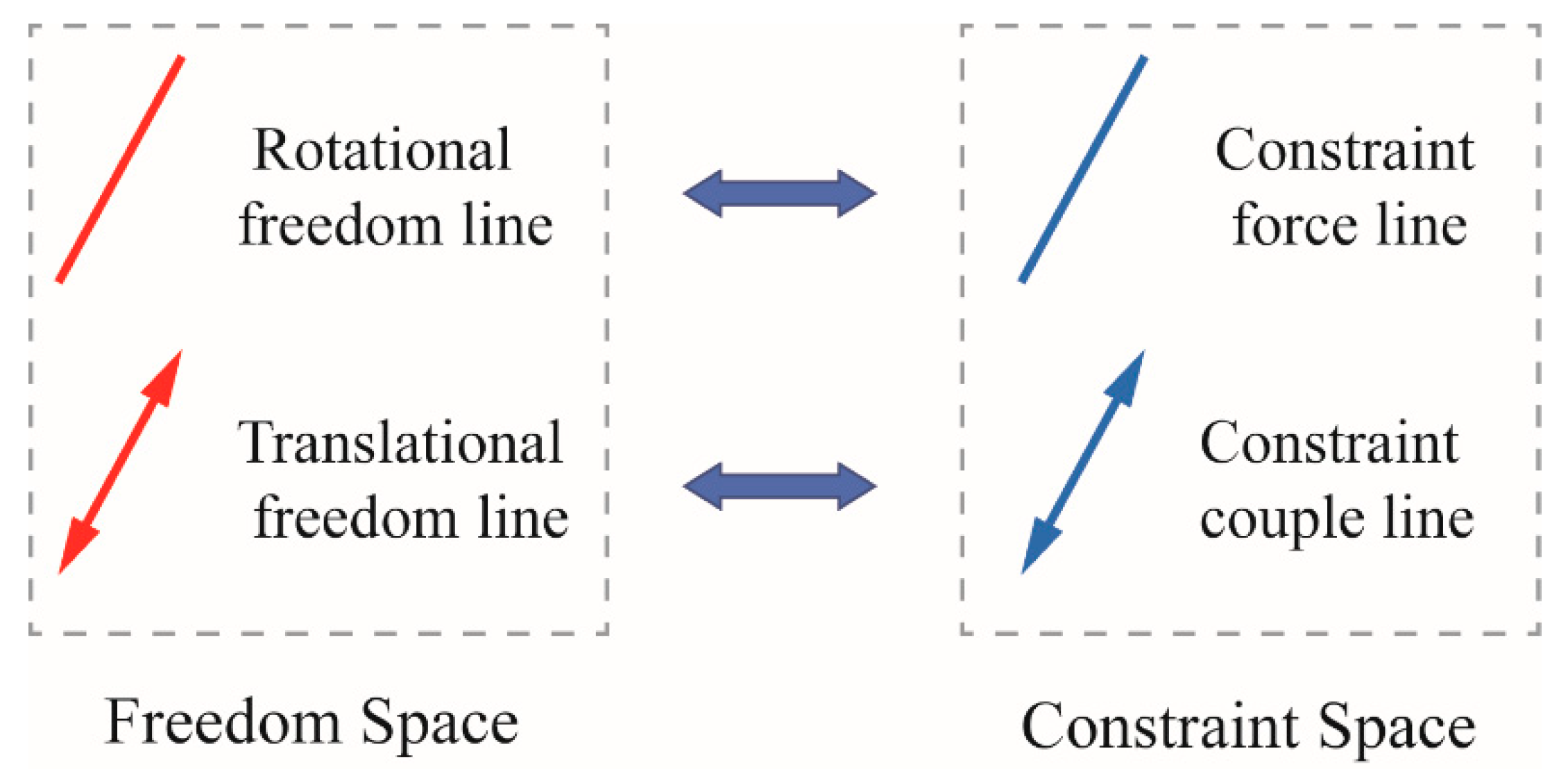
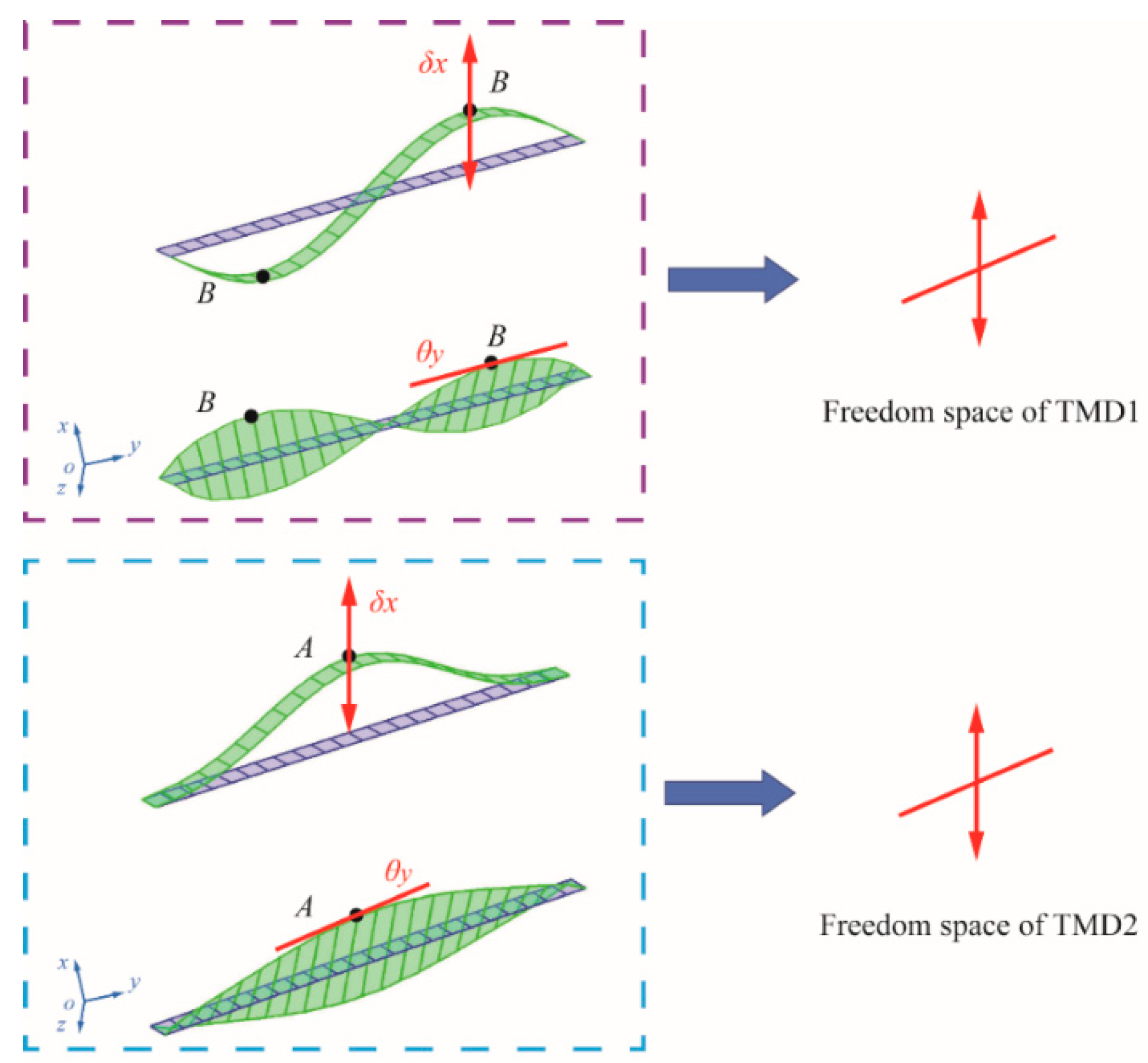
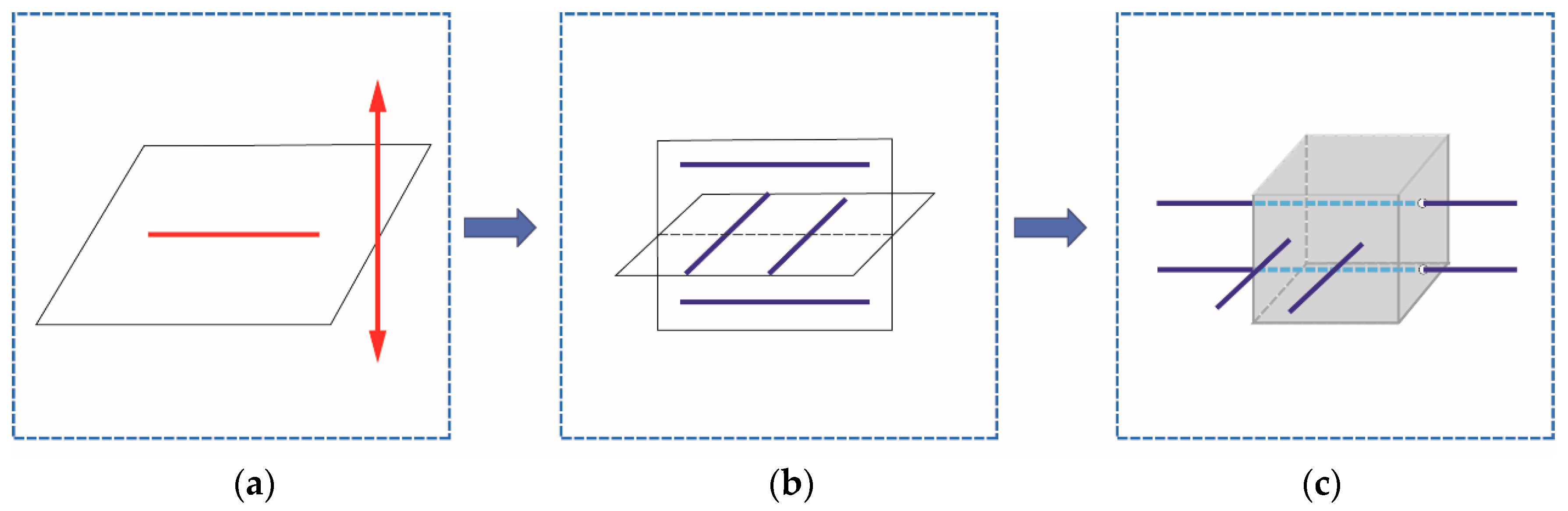
4.1. Graphical Approach

The screw theory as the theoretical foundation of graphical approach have been widely applied to design and analysis the compliant mechanisms [37,38]. For object behavior design, adding constraints is the most important step to reach the specific motion. Thus, finding the relationship between the constraints and movements is indispensable in TMD design. Currently, the screw theory is the most popular way to describe this relationship. In the screw theory, a unit screw $ is defined by a straight line with an associated pitch and is represented as a pair of three-dimensional vectors:
$ = [ s s 0 + h s ] = [ s r × s + h s ] ,
where s0 = r × s defines the moment of the screw axis about the origin of a coordinate system, s is a unit vector parallel the screw axis, r is the position vector of any point on the screw axis with respect to the origin of a coordinate system, and h is the pitch of the screw. If h is equal to zero, the screw reduces to a line quantity (Figure 6a):
$ t = [ s s 0 ] = [ s r × s ] ,
If h is infinite, the screw reduces to:
$ w = [ 0 s ] ,
In addition, an infinite-pitch screw can be considered as a line located at infinity, as shown in Figure 6b.
For a better understanding and applicability, the two special cases of unit screw ($t, $w) are visualized by geometric patterns in Figure 7. The unit screw of zero pitch ($t) stands for a pure rotation in freedom space (rotational freedom line) or a unit pure force in static along the line in constraint space (constraint force line). A unit screw of infinite pitch represents a pure translation in freedom space (translational freedom line) or a pure couple in constraint space (constraint couple line). It is worth noting that the rotational freedom line represents the axis of rotational movement, and the constraint couple line stands for the axis of couple imposed on a rigid body.
Based on Maxwell’s principles of constraints, the freedoms and constraints in a mechanical system can be defined as:
N = 6 n ,
where N is the number of DOFs, n is the number of non-redundant constraints. When a rigid body (e.g., TMD) is constrained by several mechanical connections providing n constraints, while N DOFs of the body will remains. In this regard, based on the reciprocal screw theory, n non-redundant constraints form a wrench $1 in constraint space, and the remained DOFs constitute a twist $2 in freedom space [39]. Based on the definition, the reciprocity of these two screw systems is expressed as:
$ 1 T Δ $ 2 = s 1 ( r 2 × s 2 + h 2 s 2 ) + s 2 ( r 1 × s 1 + h 1 s 1 ) = ( h 1 + h 2 ) ( s 1 s 2 ) + ( r 2 r 1 ) ( s 2 × s 1 ) = ( h 1 + h 2 ) cos α 12 a 12 sin α 12 = 0
where Δ = ( 0 I I 0 ) , a12 is the normal distance of the two screw axes and α12 is the twist angle between the two screws. h1 and h2 denote the pitch of $1 and $2, respectively.
Thus, according to Equation (27), the relationship between the freedom lines and the constraint lines can be written as a brief form in Table 3.
The 2DOFs TMD with the expected DOFs and mode shapes can be designed by the above geometric relationship.

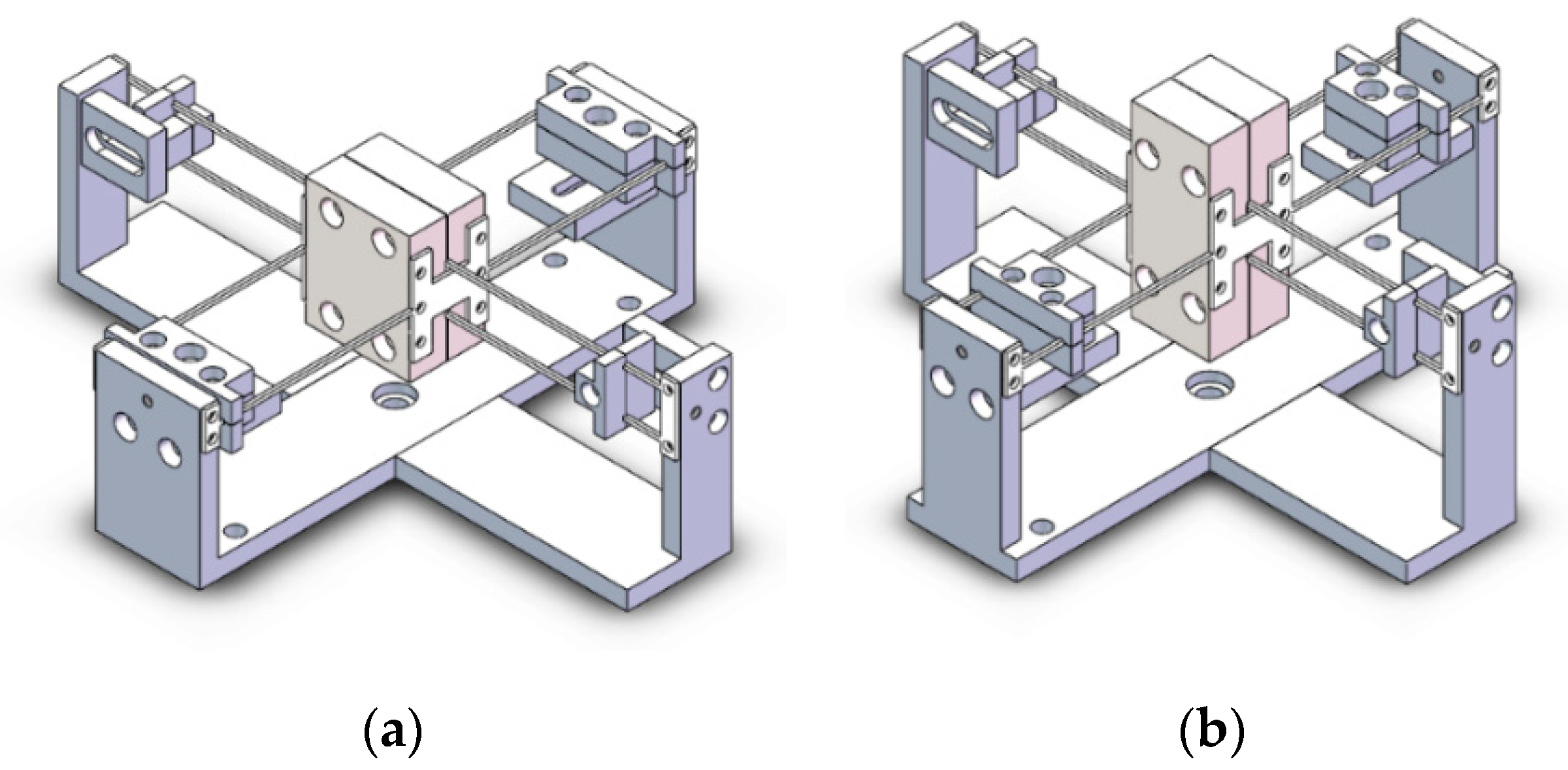
4.2. Conceptual Design of the TMDs

By studying the characteristics of human-induced vibration, it is found that the first four modes of suspension bridge are easy to be stimulated to produce resonance phenomenon, which is the primary target of vibration reduction. The targeted mode shapes are shown in Figure 8.
The optimal location of a TMD is at the maximum modal displacement. Hence, the center of the deck (point A) is the optimal location for the second bending and the first torsional modes of the deck (2B,1T), while for the first bending and the second torsional modes (1B,2T), it is at the quarter length of the deck (point B). The motion of the TMDs only along the vibration direction of the two pairs can reach the best vibration control. Two TMDs have the same geometric relationship as shown in Figure 9. Therefore, the dimension of the freedom space N is two, and the dimension of the constraint space is four, according to Equation (26).
The translational freedom line and rotational freedom lines are orthogonal in Figure 9a. For the constraint space, the four constraint force lines intersect with the rotational freedom line and are orthogonal with the translational freedom line. Here the constraint couple lines can be ignored due to the fact that four constraint force lines have already formed the expected constraints. Thus, the corresponding constraint space can be divided into two pairs, each pair contains two parallel constraint force lines, and these two pairs are orthogonal (Figure 9b). Then constraint force lines are implemented by flexure elements, each of them can provide single DOF constraint along its axial direction (Figure 9c). Therefore, the exact constraints are formed on the TMDs and the expected DOFs are defined.

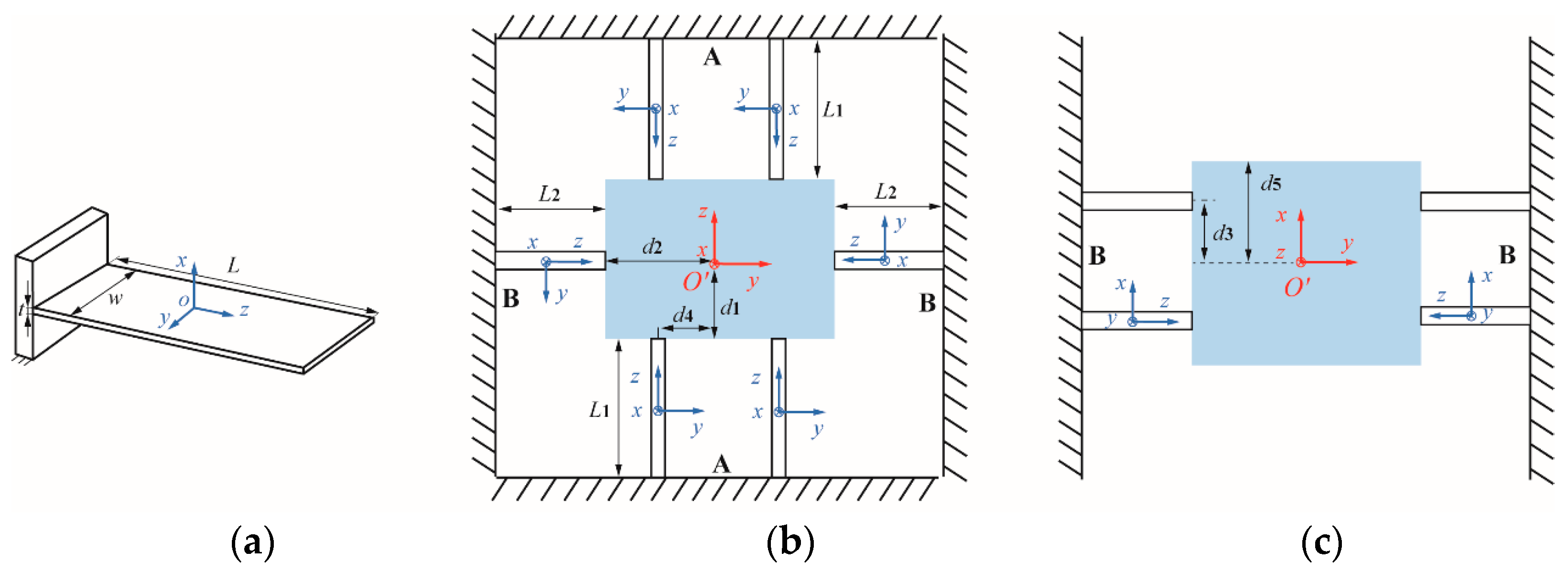
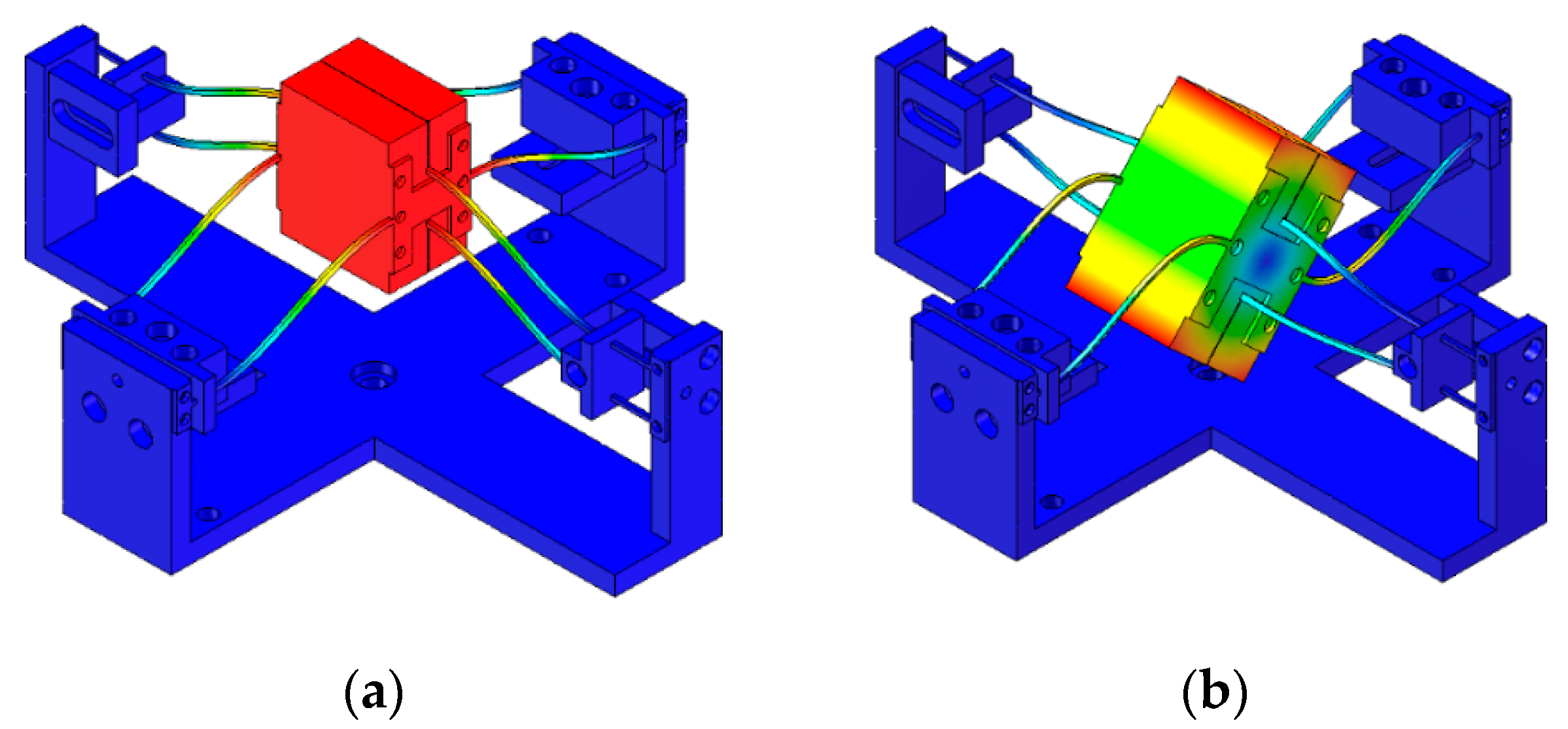
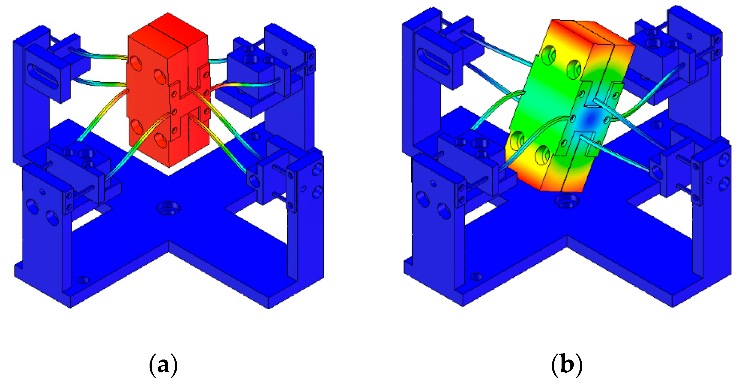
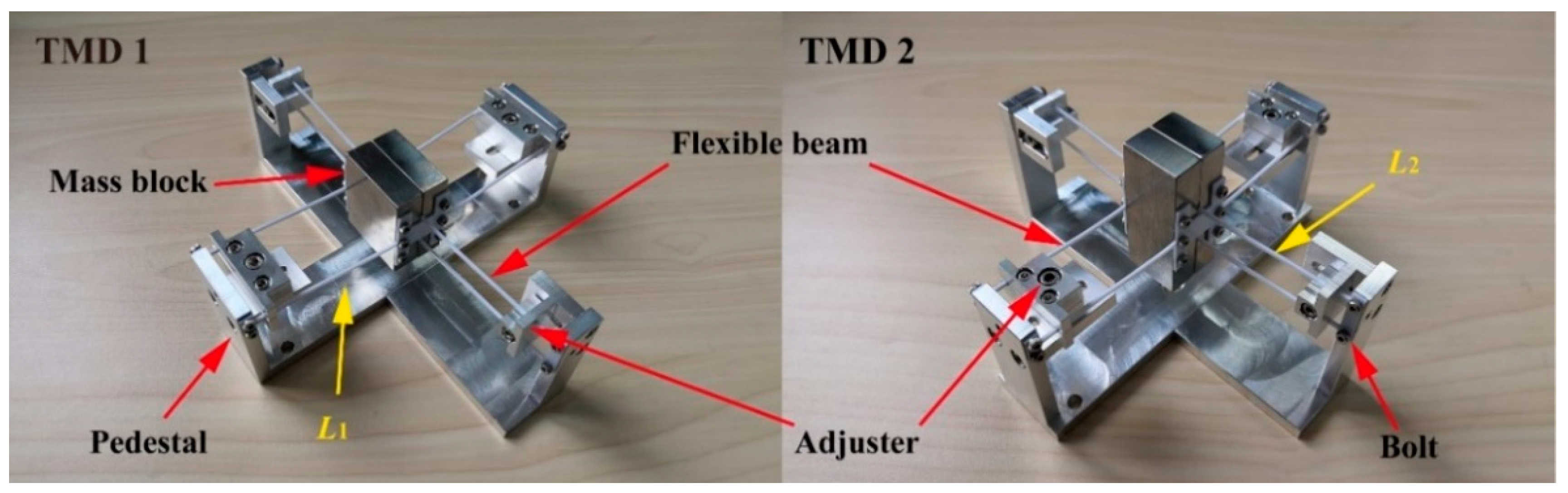
4.3. Parametric Design of 2DOFs TMDs

The conceptual model of TMDs only have two expected DOFs, but in actual design, due to the material and geometric properties, the TMD may have more DOFs than expected. The corresponding redundant modes of TMD may affect the performance of TMD, even lead to TMD failure. This is a key problem that has been perplexing TMD design. In general, the redundant modes which are far from the targeted modes can be ignored, and the empirical design has always been the major tool to achieve this goal. However, as the number of DOF increases, the empirical method gradually fails to realize the complex design of TMDs. Furthermore, the empirical design may cause the increase in time and cost. Therefore, the theoretical guidance has become particularly important in the multi-DOFs TMD design. In this section, we introduce a parameterized compliance approach for parametric design of the 2DOFs TMD.
Figure 10 shows the configuration of the TMD. It can be seen that the TMD is formed by eight slender beams in parallel distributed on mass block, which is transformed from physical models (Figure 9c). Each slender beam is considered as cantilever beam (Figure 10a) with length L, width w, and thickness t. Then, according to the Bernoulli-Euler model, the compliance matrix Ccp (p = 1, …, n) for each slender beam at location coordinate system Oxyz is given as follows:
C c p = L p E I y d i a g { α 1 1 χ γ L p 2 12 L p 2 12 α L p 2 12 β } ,
where:
α = ( t w ) 2 , β p = ( t L p ) 2 , χ = G E = 1 2 ( 1 + ν ) , γ = J I y ,
and
I x = w 3 t 12 , I y = w t 3 12 , J = I x + I y ,
where G, E is the shear and Young’s modulus, respectively. γ is the ratio of torsion constant over moment of inertia, ν is the Poisson’s ratio.
Further, to simplify the following non-dimensionalization, we choose t = w, and according to Equations (29) and (30), γ = 2. Due to the different length of slender beam (L1, L2 and s = L1/L2), the compliance matrix of two type slender beams can be written as:
C c A = L 2 E I y diag [ s s s 2 χ s 3 L 2 2 12 s 3 L 2 2 12 s L 2 2 12 β 2 ] ,
C c B = L 2 E I y diag [ 1 1 1 2 χ L 2 2 12 L 2 2 12 L 2 2 12 β 2 ] ,
In order to combine the local compliance matrix Ccp of the eight slender beams, they should be transformed from the local to global coordinate system. The origin O’ of the global coordinate system O’XYZ is defined in the centroid of the mass block (Figure 10b). For the parallel flexure mechanism, the global compliance matrix can be given as:
C s = ( p = 1 m ( A d p C c p A d p T ) 1 ) 1 ,
where m is the number of slender beams; Adp is the adjoint transformation matrix from the pth element to the global system:
A d p = [ R x , y , z ( θ ) 0 T R x , y , z ( θ ) R x , y , z ( θ ) ] ,
where T is the translation matrix. Rx,y,z(θ) = Rx(θ)Ry(θ)Rz(θ), which is the multiplication of rotation matrices. Rx(θ), Ry(θ), and Rz(θ) stand for the rotation matrices by an angle θ about the x, y, and z axis, respectively. They are given in Equation (35):
R x ( θ ) = [ 1 0 0 0 cos θ sin θ 0 sin θ cos θ ] , R y ( θ ) = [ cos θ 0 sin θ 0 1 0 sin θ 0 cos θ ] , R z ( θ ) = [ cos θ sin θ 0 sin θ cos θ 0 0 0 1 ] ,
For the vector (Δx, Δy, Δz)T between two position, the translation matrix can be expressed as
T = [ 0 Δ z Δ y Δ z 0 Δ x Δ y Δ x 0 ] ,
Based on Equations (33)–(36), the global compliance matrix of TMD is computed by:
C s = L 2 E I y [ c 11 c 22 c 33 c 44 c 55 c 66 ] ,
The principal diagonal elements of Cs are selected as follows:
c 11 = L 2 2 β 2 s 3 16 ( 1 β 2 L 2 2 s 3 + β 2 L 2 2 s 2 + 3 β 2 L 2 d 1 s + 3 β 2 L 2 d 1 s 3 + 3 β 2 d 1 2 + 3 β 2 d 2 2 s 3 + 3 d 4 2 s 2 ) c 22 = L 2 2 s 3 16 ( 1 0.5 χ L 2 2 s 3 + L 2 2 s 2 + 3 L 2 d 1 s + 3 d 1 2 + 3 d 3 2 s 3 ) c 33 = L 2 2 β 2 s 3 16 ( 1 β 2 L 2 2 s 3 + 0.5 χ β 2 L 2 2 s 2 + 3 β 2 L 2 d 2 s 3 + 3 β 2 d 2 2 s 3 + 3 d 3 2 s 3 + 3 β 2 d 4 2 ) c 44 = L 2 2 s 3 48 ( 1 s 3 + 1 ) c 55 = L 2 2 β 2 s 3 48 ( 1 s 3 + β 2 ) c 66 = L 2 2 β 2 s 16 ( 1 β 2 s + 1 ) ,
where c11, c22, and c33 are the rotational compliance/stiffness about the x, y and z axis while c44, c55, and c66 are the translational compliance/stiffness along the x, y and z axis, respectively. In the end, the natural frequencies of 2DOFs TMDs can be approximate calculated by Equations (39)–(41).
The bending mode:
ω 1 = 1 2 π k 44 m d = 1 2 π 1 m d ( L 2 c 44 E I y ) 1 ,
The torsional mode:
ω 2 = 1 2 π k 22 I Y = 1 2 π 1 I Y ( L 2 c 22 E I y ) 1 ,
and:
I Y = 1 3 m d ( d 1 2 + d 5 2 ) ,
where d5 is the height of mass block (Figure 10c).

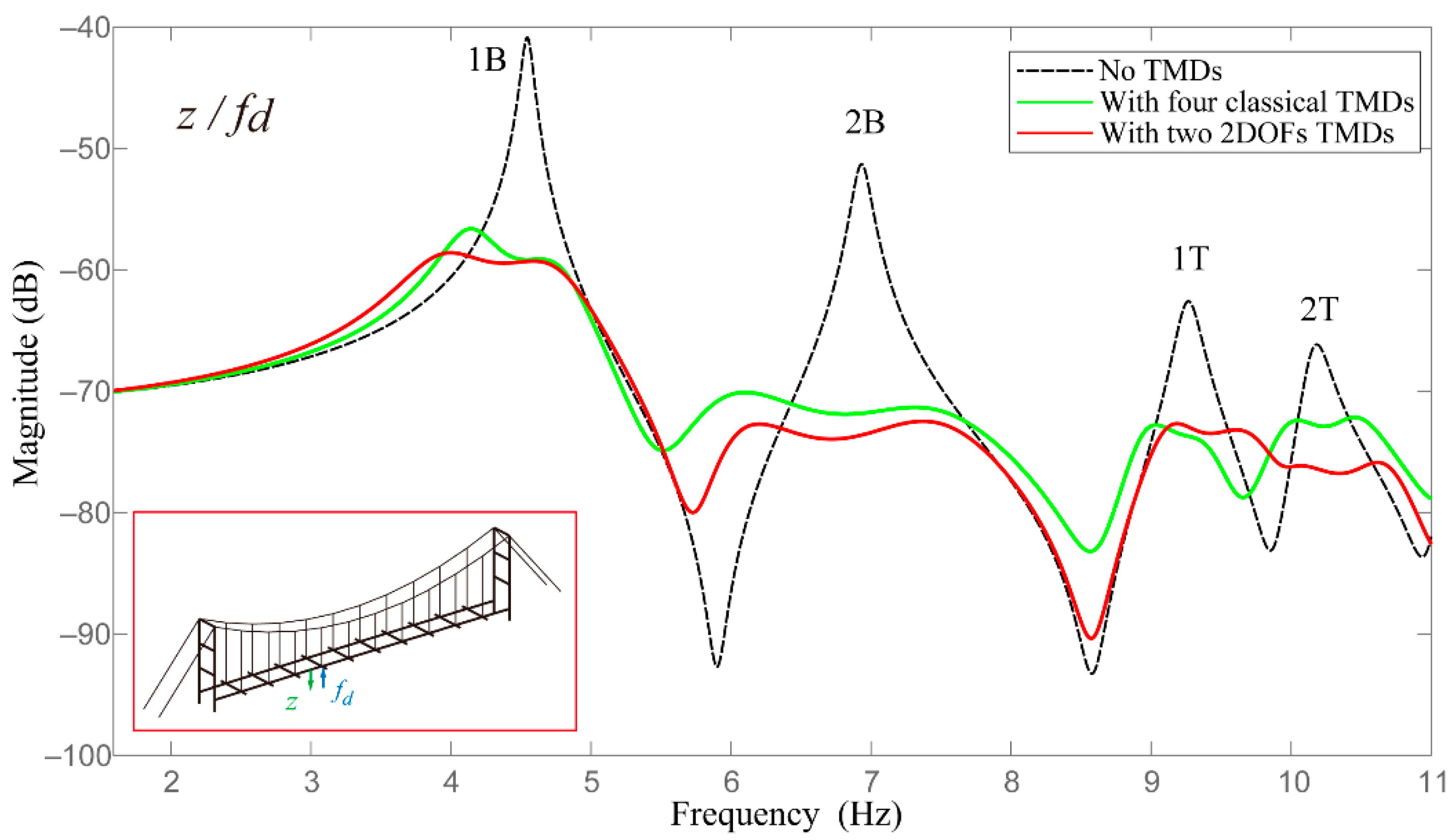
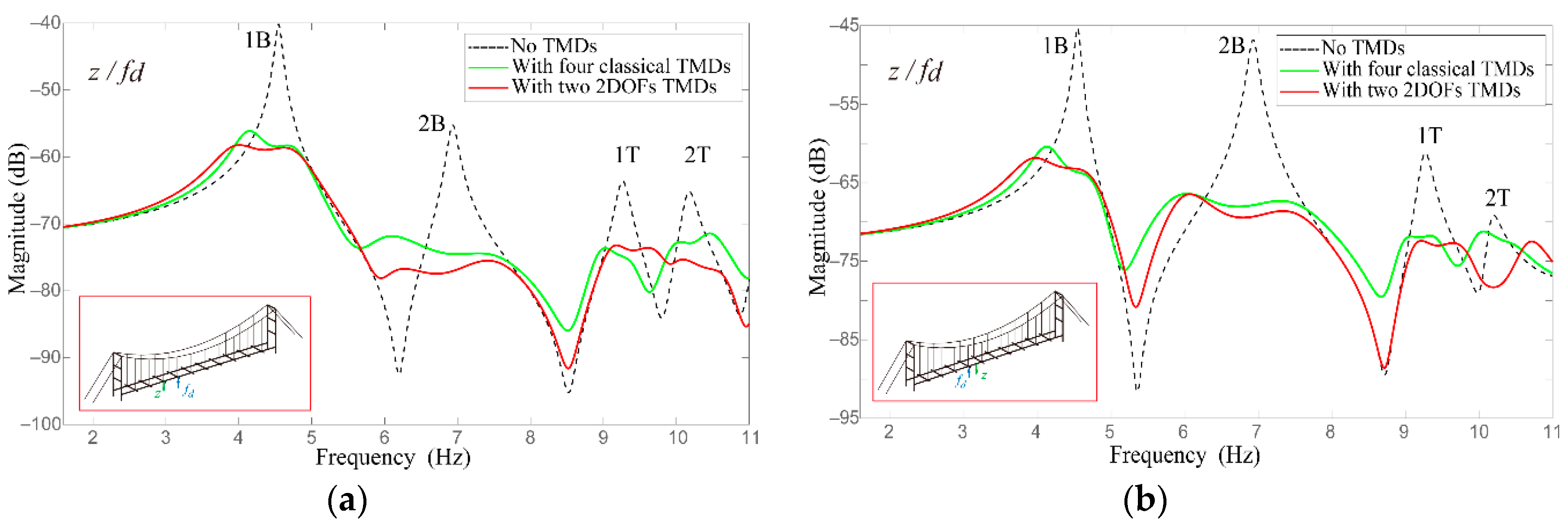
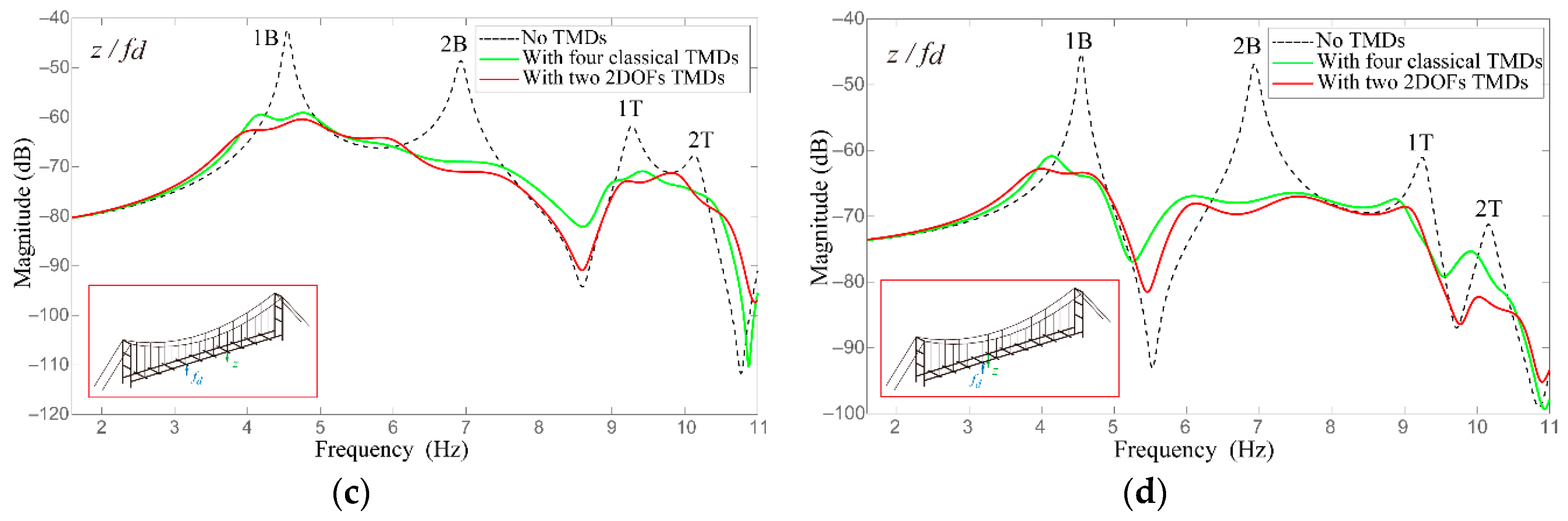
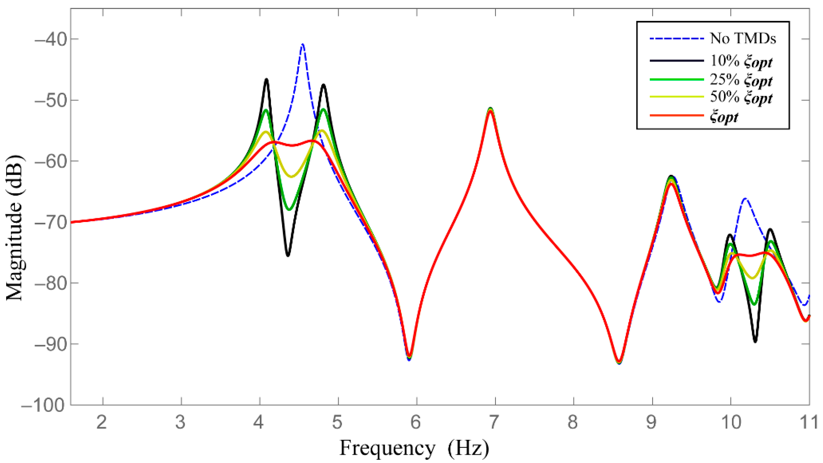
4.4. Results and Discussion

According to the optimum frequency ratios νi (Table 2) and the target modes of bridge, the expected modes of TMDs are obtained and listed in Table 4.
In general, the size of TMD should be smaller and not occupy the space of bridge as much as possible. Thus, considering the processing conditions and the size of deck, we choose t = w = 1mm. The mass block is iron and md = 0.18 kg. The material of slender beams is Acrylonitrile Butadiene Styrene (ABS), and the elastic modulus E = 2 GPa, χ = 0.37, the Poisson’s ratio ν is 0.394. In addition, in order to simplify calculation and TMD design, let d4 = d2.
The calculation results of 2DOFs TMDs are summarized in Table 5. It is noticed that the three-order natural frequency ω3 are about 7 times greater than ω2, and ω4 is much larger than ω1 and ω2. Therefore, the undesired DOFs can be neglected, and the expected 2DOFs TMDs are obtained. According to the dimension parameters, FE model of 2DOFs TMDs are built as shown in Figure 11. The mode shapes of two expected TMDs are shown in Figure 12 and Figure 13, respectively.

5. Experimental Verification

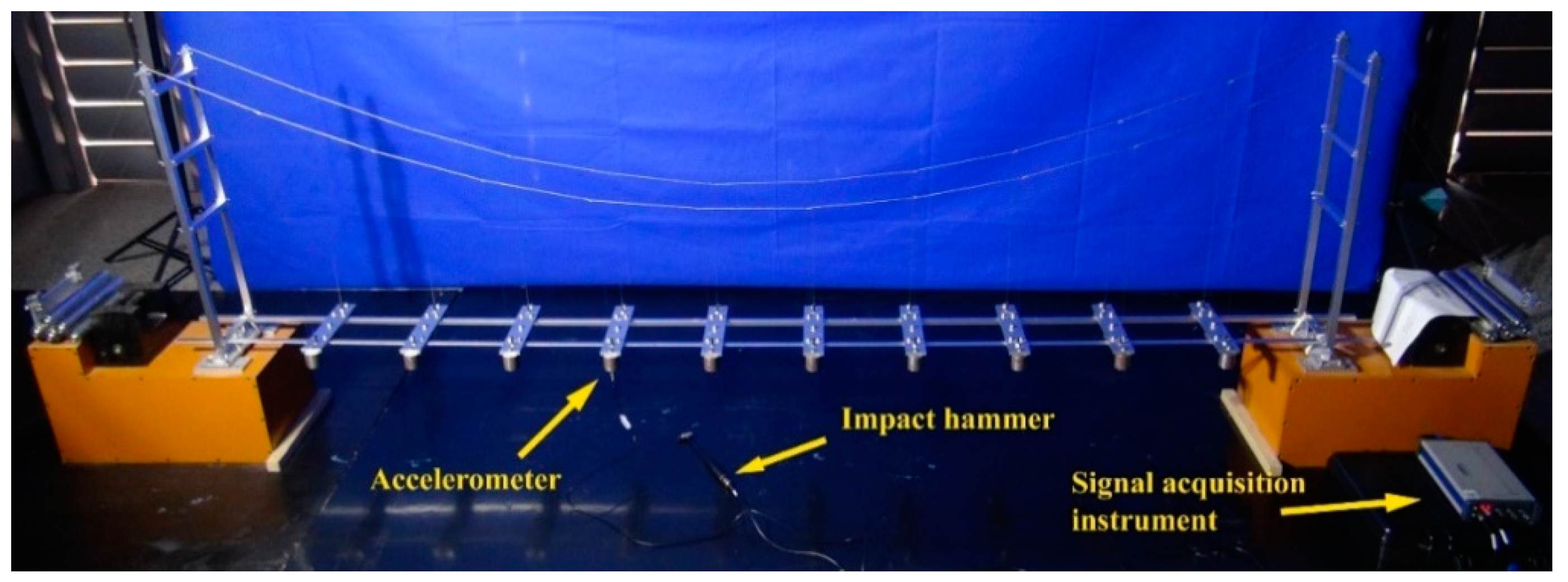
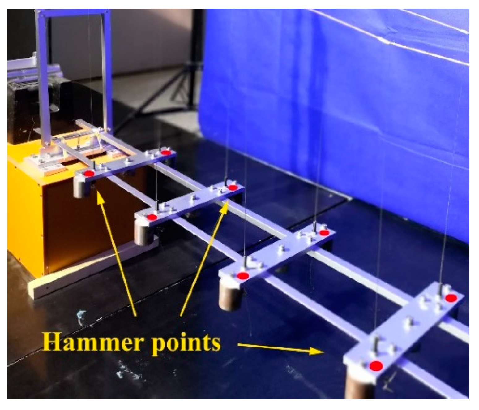
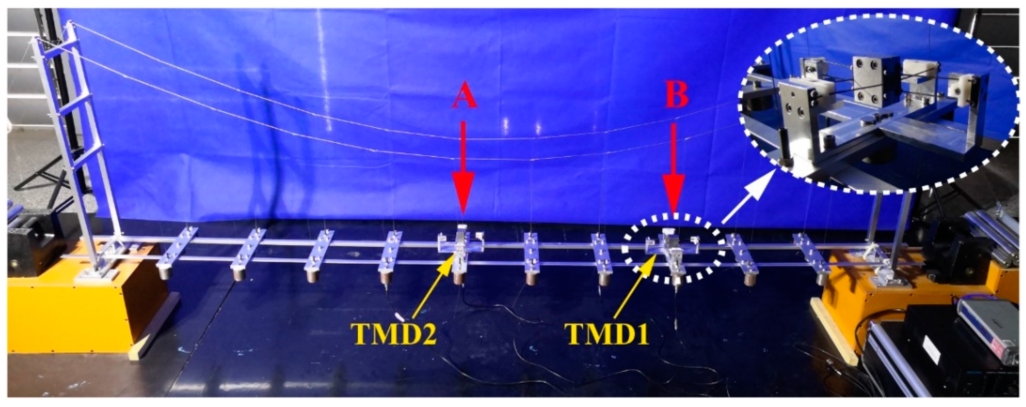
5.1. Experimental Setup

The laboratory mock-up of the suspension bridge (in Figure 14) is used to investigate the performance of the 2DOFs TMDs. An impact hammer is used to excite the structure. Prior to vibration measurements, the data acquisition system is established, which involves a single-axial accelerometer, positioned to measure vertical accelerations. The position of the accelerometer is illustrated in Figure 14. The output data are obtained by successive hammering all positions on the deck (Figure 15). The modal parameters of the bridge are estimated by hammering method. The natural frequencies and mode shapes of the mock-up are shown in Table 1.

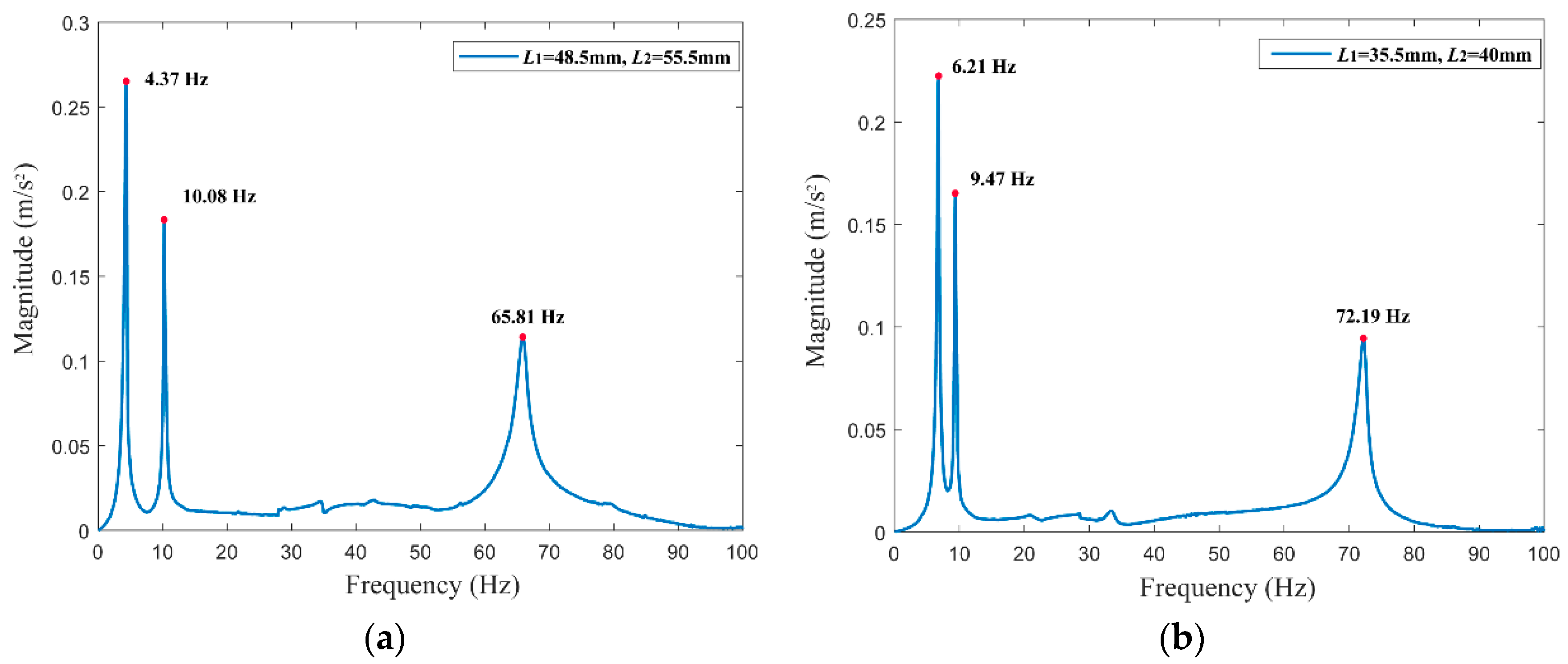
5.2. Hammer Tests of TMDs

The structure of 2DOFs TMDs with adjustable natural frequencies is presented in Figure 16. Each TMD consists a mass block, two pedestals, and eight flexible beams with adjusters. For each flexible beam, one side is fixed on the pedestal by bolts and the other side is connected to the mass block. Though changing the positions of the adjuster, the effective length of the flexible beam can be adjusted, then tunable stiffness of the TMD is realized. The adjuster not only improves the tuning ability of TMD, but also compensates for the errors. The errors include the machining error and the calculation error which is caused by ignoring the prestress of flexible beams (Equations (39) and (40)). Thus, the adjuster is an indispensable part of the TMDs.
Based on Equations (39) and (40), the natural frequencies of 2DOFs TMDs are determined by the dimensions of the flexible beams. In order to improve the tuning ability at runtime, the TMDs are designed with tunable L1 and L2 which is the effective length of the flexible beams (Figure 16).
In hammer tests, the TMDs are excited by an INV9311impact hammer, and the acceleration responses are recorded by a PSV-500-1D scanning laser vibrometer. The experimental results are shown in Figure 17. The figure shows the experimental acceleration responses of the designed 2DOFs TMDs: (a) when L1 = 48.5 mm, L2 = 55.5 mm, the first three order frequency of TMD1 is 4.37 Hz, 10.08 Hz, and 65.81 Hz; (b) when L1 = 37.5 mm, L2 = 40 mm, the first three order frequency of TMD2 is 6.21 Hz, 9.47 Hz, and 72.19 Hz. Comparing with the first two order frequency, the third order frequency of TMDs is a relatively large value, which is far beyond the bandwidth (0–15 Hz) we are considering. Therefore, the 2DOFs TMDs meet the design requirements and verify the validity of the theoretical model.

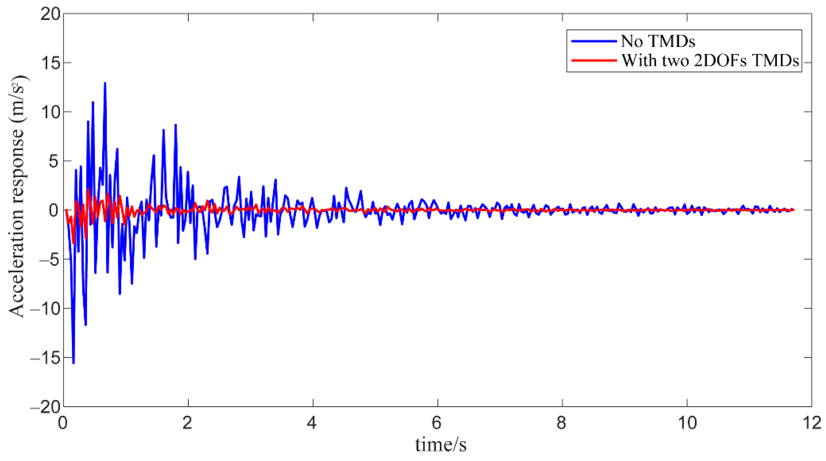
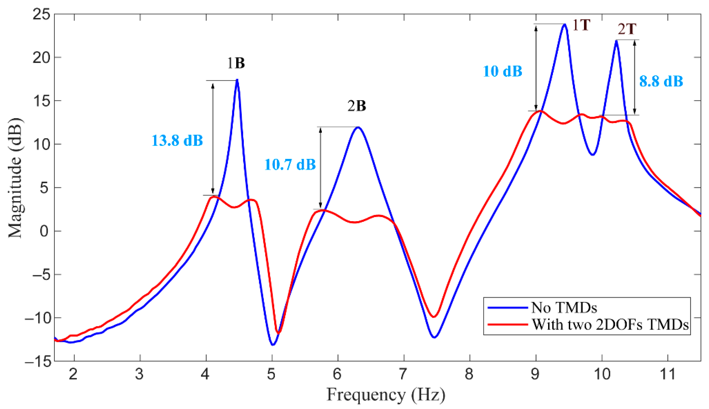
5.3. Vibration Suppression of Bridge with TMDs

The designed 2DOFs TMDs are mounted on point A and point B, which has discussed in Section 4.2. Figure 18 shows a close view of the TMD1 (shown in Figure 12); except the different dimension parameters, the two TMDs have the same configuration and can be tuned in the same way. For damping the target modes, the optimum FRF of these two TMDs exhibits two distinct modes at 4.37 Hz, 10.08 Hz, and 6.21 Hz, 9.47 Hz, respectively, as shown in Figure 17.
By referring the previous design [27], the damping is introduced by using eddy current damping, where two symmetric powerful magnets are attached on the pedestal below the mass block of the TMD in Figure 19. The damping value can be tuned by manually adjusting the size and number of the magnets. In Figure 19, the replaceable magnets are used to set the translational damping and the rotational damping at the same time. If necessary, another two symmetric magnets which are attached on the pedestal (the position at the red dashed circles in Figure 19) can provide additional damping for the bending mode.
The experimental results are shown in Figure 20 and Figure 21. The Figure 20 shows the acceleration responses of the deck: (i) without TMD, (ii) when the structure is equipped with two 2DOFs. The result shows that the 2DOFs TMD is very effective in vibration damping of the bridge. In order to quantitatively confirm the performance of TMDs, Figure 21 shows the FRFs of the deck: (i) without TMD, (ii) when the structure is equipped with two 2DOFs TMDs, targeting the mode pairs (2B,1T) and (1B,2T), respectively. One sees that TMD1 can attain 13.8 dB amplitude reduction of the first bending mode (1B) and 8.8 dB amplitude reduction of the second torsional mode (2T); Meanwhile, a 10.7 dB amplitude reduction of the second bending mode (2B) is observed after using TMD2, and 10 dB amplitude reduction of the first torsional mode (1T).
The experimental results indicate that the 2DOFs TMDs which designed under the kinematic constraint theory guidance can target the bending and the torsion modes at the same time. Comparing with the classical TMD, the 2DOFs TMD not only achieves vibration reduction, but also avoids increasing the load of the bridge. It is worth mentioning that the final frequency ratios are different from the optimized frequency ratios (Table 4). The optimized frequency ratios are the result of theoretical model calculation. However, the error between the theoretical model and the real structure, as well as the machining and calculation errors, may result in the change of the final frequency ratios. But the role of the optimized frequency ratios in the TMD structural parameter design cannot be neglected.

6. Conclusions

This study proposed a synthetic approach to design and implement 2DOFs TMDs for damping the bending and torsional modes of suspension bridges. For verifying the effectiveness of the concept model, we cast the parameter optimization of the 2DOFs TMDs conceptual model as a control problem with decentralized static output feedback for minimizing the response of the bridge deck. The optimized frequency ratios play a significant role in the TMD structural parameter design. For designing the expected modes of the 2DOFs TMDs, the graphical approach is introduced to arrange flexible beams properly according to the exact constraints. Based on the optimized frequency ratios, the dimensions of TMDs are determined by the compliance matrix method. The proposed design has been simulated and implemented successfully on a suspension bridge mock-up. Based on the presented results and interpretations, the main findings are summarized as follows:
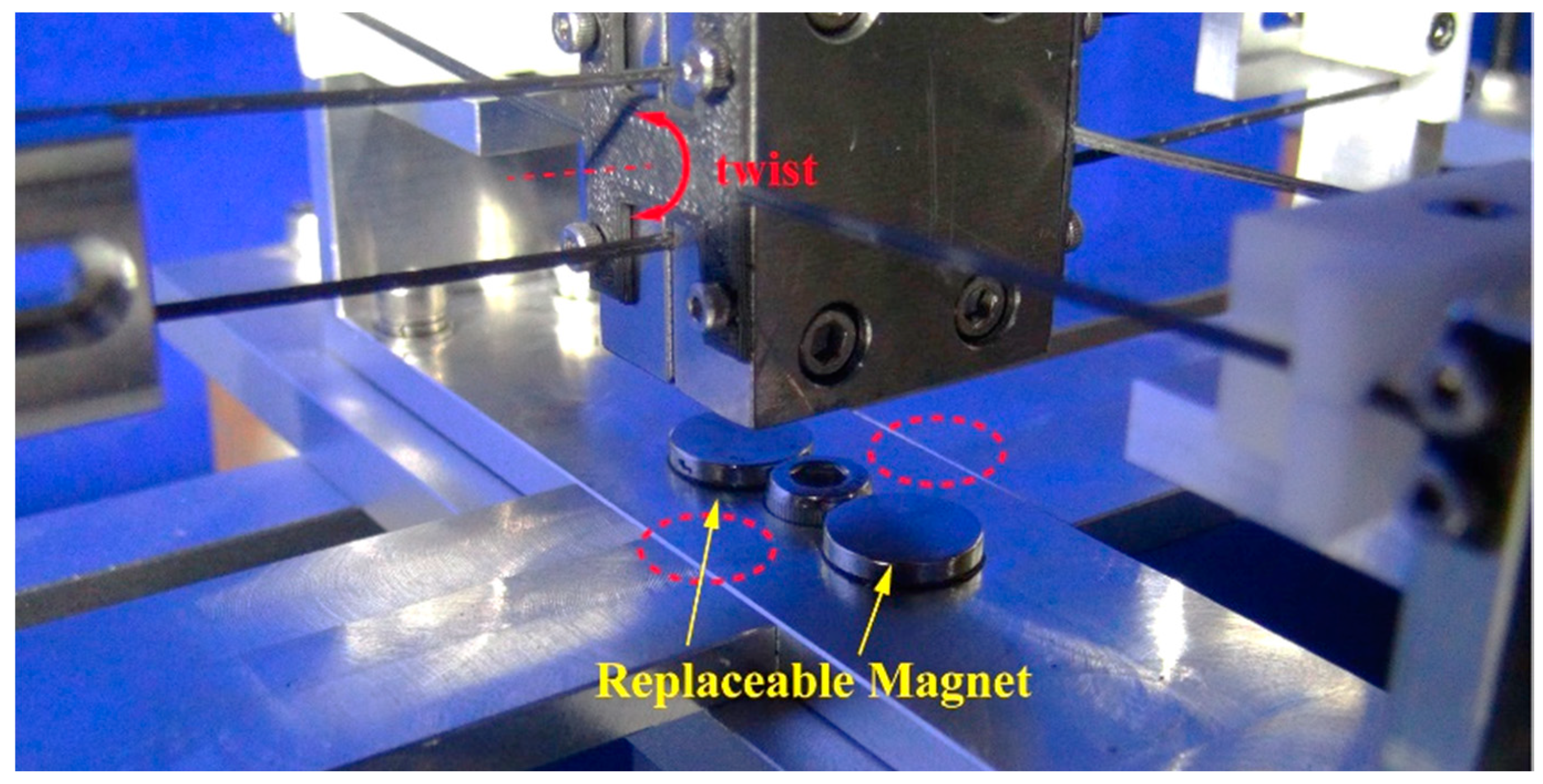
  • The synthetic approach based on both the graphical approach and parameterized compliance is an effective way to design the TMD with the expected DOFs (i.e., 1, 2, …, 6). It is also an effective complement to the empirical design for the multi-DOFs TMD. Comparing with the empirical design, this synthetic approach can design the expected multi-DOFs TMD without much design experience, which can save time and cost. The disadvantage of this method is that the influence of prestress is not taken into account in the theoretical model. Thus, the adjuster is an indispensable part of TMDs.
  • This study verifies the feasibility of the two 2DOFs TMDs in vibration reduction of suspension bridges by numerically and experimentally; comparing with the classical configuration of the TMD, the two 2DOFs TMDs can reduce the weight penalty. The experiment demonstrates the ability of the TMDs for suppressing several vibration modes under laboratory conditions. However, their implementation in a full-scale bridge still needs further research.

Author Contributions

All authors discussed and agreed upon the idea and made scientific contributions. The original idea of the article was provided by F.M. and he also designed the methodology, realized its MATLAB program, and wrote the manuscript; J.W., Y.X. and Y.M. provided with the support of the entire study and revised the manuscript; J.Y. gave suggestions in the theoretical analyses and tests. All authors have read and agreed to the published version of the manuscript.

Funding

This research was funded by the Science and Technology Research Project of State Grid (Research on Key Technologies for Improving Impact Resistance of Suspension Spanning Frame, Grant No. 5442GC180003).

Acknowledgments

The authors thank André Preumont of Active Structures Laboratory from Université Libre de Bruxelles, Brussels, Belgium for his kind guidance and suggestions in the whole research process; and thank the colleagues of FMRL lab from Beihang University, Beijing, China for the realization of the experimental set-up. The reviewers are very much acknowledged.

Conflicts of Interest

The authors declare no conflict of interest.

References

  1. Ubertini, F.; Comanducci, G.; Laflamme, S. A parametric study on reliability-based tuned-mass damper design against bridge flutter. J. Vib. Control. 2017, 23, 1518–1534. [Google Scholar] [CrossRef]
  2. Wang, Z.; Yue, F.; Gao, H. Free Vibration of a Taut Cable with Two Discrete Inertial Mass Dampers. Appl. Sci. 2019, 9, 3919. [Google Scholar] [CrossRef] [Green Version]
  3. Shi, W.; Wang, L.; Lu, Z.; Zhang, Q. Application of an Artificial Fish Swarm Algorithm in an Optimum Tuned Mass Damper Design for a Pedestrian Bridge. Appl. Sci. 2018, 8, 175. [Google Scholar] [CrossRef] [Green Version]
  4. Lievens, K.; Lombaert, G.; De Roeck, G.; Van den Broeck, P. Robust design of a TMD for the vibration serviceability of a footbridge. Eng. Struct. 2016, 123, 408–418. [Google Scholar] [CrossRef]
  5. Caetano, E.; Cunha, Á.; Moutinho, C.; Magalhães, F. Studies for controlling human-induced vibration of the Pedroe Inês footbridge, Portugal. Part 2: Implementation of tuned mass dampers. Eng. Struct. 2010, 32, 1082–1091. [Google Scholar] [CrossRef]
  6. Van Nimmen, K.; Verbeke, P.; Lombaert, G.; De Roeck, G.; Van den Broeck, P. Numerical and experimental evaluation of the dynamic performance of a footbridge with tuned mass dampers. J. Bridge Eng. 2016, 21, C4016001. [Google Scholar] [CrossRef]
  7. De Domenico, D.; Ricciardi, G. Improving the dynamic performance of base-isolated structures via tuned mass damper and inerter devices: A comparative study. Struct. Control Health Monit. 2018, 25, e2234. [Google Scholar] [CrossRef]
  8. De Domenico, D.; Ricciardi, G.; Takewaki, I. Design strategies of viscous dampers for seismic protection of building structures: A review. Soil Dyn. Earthq. Eng. 2019, 118, 144–165. [Google Scholar] [CrossRef]
  9. Hao, L.F.; Zhang, R.F. Structural safety redundancy-based design method for structure with viscous dampers. Struct. Eng. Mech. 2016, 59, 821–840. [Google Scholar] [CrossRef]
  10. Preumont, A.; Voltan, M.; Sangiovanni, A.; Mokrani, B.; Alaluf, D. Active tendon control of suspension bridges. Smart Struct. Syst. 2016, 18, 31–52. [Google Scholar] [CrossRef]
  11. De Domenico, D.; Deastra, P.; Ricciardi, G.; Sims, N.D.; Wagg, D.J. Novel fluid inerter based tuned mass dampers for optimised structural control of base-isolated buildings. J. Frankl. Inst. 2018, 14, 7626–7649. [Google Scholar] [CrossRef] [Green Version]
  12. Tian, L.; Rong, K.; Zhang, P.; Liu, Y. Vibration Control of a Power Transmission Tower with Pounding Tuned Mass Damper under Multi-Component Seismic Excitations. Appl. Sci. 2017, 7, 477. [Google Scholar] [CrossRef]
  13. Zhang, R.F.; Zhao, Z.P.; Dai, K.S. Seismic response mitigation of a wind turbine tower using a tuned parallel inerter mass system. Eng. Struct. 2019, 180, 29–39. [Google Scholar] [CrossRef]
  14. Mekki, O.B.; Bourquin, F.; Maceri, F.; Merliot, E. Unimodal optimal passive electromechanical damping of elastic structures. Smart Mater. Struct. 2013, 22, 085029. [Google Scholar] [CrossRef]
  15. Mekki, O.B.; Bourquin, F.; Maceri, F.; Van Phu, C.N. An adaptive pendulum for evolving structures. Struct. Control Health Monit. 2012, 19, 43–54. [Google Scholar] [CrossRef]
  16. Elias, S.; Matsagar, V. Research developments in vibration control of structures using passive tuned mass dampers. Annu. Rev. Control 2017, 44, 129–156. [Google Scholar] [CrossRef]
  17. Casalotti, A.; Arena, A.; Lacarbonara, W. Mitigation of post-flutter oscillations in suspension bridges by hysteretic tuned mass dampers. Eng. Struct. 2014, 69, 62–71. [Google Scholar] [CrossRef]
  18. Chen, S.R.; Wu, J. Performance enhancement of bridge infrastructure systems: Long-span bridge, moving trucks and wind with tuned mass dampers. Eng. Struct. 2008, 30, 3316–3324. [Google Scholar] [CrossRef]
  19. Li, Q.; Fan, J.; Nie, J.; Li, Q.; Chen, Y. Crowd-induced random vibration of footbridge and vibration control using multiple tuned mass dampers. J. Sound Vib. 2010, 329, 4068–4092. [Google Scholar] [CrossRef]
  20. Daniel, Y.; Lavan, O.; Levy, R. Multiple-tuned mass dampers for multimodal control of pedestrian bridges. J. Struct. Eng. 2011, 138, 1173–1178. [Google Scholar] [CrossRef]
  21. Tubino, F.; Carassale, L.; Piccardo, G. Human-induced vibrations on two lively footbridges in Milan. J. Bridge Eng. 2016, 21, C4015002. [Google Scholar] [CrossRef]
  22. Wen, Q.; Hua, X.G.; Chen, Z.Q.; Yang, Y.; Niu, H.W. Control of human-induced vibrations of a curved cable-stayed bridge: Design, implementation, and field validation. J. Bridge Eng. 2016, 21, 04016028. [Google Scholar] [CrossRef]
  23. Lin, C.C.; Wang, J.F.; Chen, B.L. Train-induced vibration control of high-speed railway bridges equipped with multiple tuned mass dampers. J. Bridge Eng. 2005, 10, 398–414. [Google Scholar] [CrossRef]
  24. Li, J.; Su, M.; Fan, L. Vibration control of railway bridges under high-speed trains using multiple tuned mass dampers. J. Bridge Eng. 2005, 10, 312–320. [Google Scholar] [CrossRef]
  25. Luu, M.; Zabel, V.; Könke, C. An optimization method of multi-resonant response of high-speed train bridges using TMDs. Finite Elem. Anal. Des. 2012, 53, 13–23. [Google Scholar] [CrossRef]
  26. Stăncioiu, D.; Ouyang, H. Structural modification formula and iterative design method using multiple tuned mass dampers for structures subjected to moving loads. Mech. Syst. Signal Process. 2012, 28, 542–560. [Google Scholar] [CrossRef]
  27. Mokrani, B.; Zhui, T.; Alaluf, D.; Meng, F.H.; Preumont, A. Passive damping of suspension bridges using multi-degree of freedom tuned mass dampers. Eng. Struct. 2017, 153, 749–756. [Google Scholar] [CrossRef]
  28. Zuo, L.; Nayfeh, S.A. The two-degree-of-freedom tuned-mass damper for suppression of single-mode vibration under random and harmonic excitation. J. Vib. Acoust. 2006, 128, 56–65. [Google Scholar] [CrossRef]
  29. Jang, S.J.; Brennan, M.J.; Rustighi, E.; Jung, H.J. A simple method for choosing the parameters of a two degree-of-freedom tuned vibration absorber. J. Sound Vib. 2012, 331, 4658–4667. [Google Scholar] [CrossRef] [Green Version]
  30. Yang, Y.; Dai, W.; Liu, Q. Design and implementation of two-degree-of-freedom tuned mass damper in milling vibration mitigation. J. Sound Vib. 2015, 335, 78–88. [Google Scholar] [CrossRef]
  31. Yang, Y.; Dai, W.; Liu, Q. Design and machining application of a two-DOF magnetic tuned mass damper. Int. J. Adv. Manuf. Technol. 2017, 89, 1635–1643. [Google Scholar] [CrossRef]
  32. Ma, W.S.; Yang, Y.Q.; Yu, J.J. General routine of suppressing single vibration mode by multi-DOF tuned mass damper: Application of three-DOF. Mech. Syst. Signal Process. 2019, 121, 77–96. [Google Scholar] [CrossRef]
  33. Meng, F.H.; Mokrani, B.; Alaluf, D.; Yu, J.J.; Preumont, A. Damage detection in active suspension bridges: An experimental investigation. Sensors 2018, 18, 3002. [Google Scholar] [CrossRef] [Green Version]
  34. Meng, F.H.; Yu, J.J.; Alaluf, D.; Mokrani, B.; Preumont, A. Modal flexibility-based damage detection for suspension bridge hangers: A numerical and experimental investigation. Smart Struct. Syst. 2019, 23, 15–29. [Google Scholar]
  35. Tubino, F.; Piccardo, G. Tuned mass damper optimization for the mitigation of human-induced vibrations of pedestrian bridges. Meccanica 2015, 50, 809–824. [Google Scholar] [CrossRef]
  36. Yu, J.J.; Li, S.; Pei, X.; Bi, S.; Zong, G. A unified approach to type synthesis of both rigid and flexure parallel mechanisms. Sci. China Technol. Sci. 2011, 54, 1206–1219. [Google Scholar] [CrossRef]
  37. Hopkins, J.B.; Culpepper, M.L. Synthesis of multi-degree of freedom, parallel flexure system concepts via Freedom and Constraint Topology (FACT)–Part I: Principles. Precis. Eng. 2010, 34, 259–270. [Google Scholar] [CrossRef]
  38. Yu, J.J.; Li, S.; Su, H.J.; Culpepper, M.L. Screw theory-based methodology for the deterministic type synthesis of flexure mechanisms. J. Mech. Robot. 2011, 3, 031008. [Google Scholar] [CrossRef]
  39. Jia, M.; Jia, R.P.; Yu, J.J. A Compliance-Based Parameterization Approach for Type Synthesis of Flexure Mechanisms. J. Mech. Robot. 2015, 7, 031014. [Google Scholar] [CrossRef]
Figure 1. Concept model of the 2DOF TMDs: the bridge system equipped with two TMDs.
Applsci 10 00457 g001
Figure 2. Block diagram of the bridge—2DOFs TMDs system with decentralized control.
Applsci 10 00457 g002
Figure 3. Numerical results: FRFs of the deck without and with the TMDs. The TMDs are targeted for the damping of the mode pair (2B,1T) and (1B,2T).
Applsci 10 00457 g003
Figure 4. Numerical results: FRFs of the deck respect to different measuring position (ad). The excitation point is fixed.
Applsci 10 00457 g004aApplsci 10 00457 g004b
Figure 5. Influence of the damping of TMD1 on the FRF of the system. ξ = 10% ξopt, 25% ξopt, 50% ξopt and ξopt, respectively.
Applsci 10 00457 g005
Figure 6. A unit screw.
Applsci 10 00457 g006
Figure 7. Geometric patterns representing screws.
Applsci 10 00457 g007
Figure 8. Shapes of the targeted modes and the corresponding optimal location of the TMD: the optimal location of the modes (2B,1T) at point A, while it is point B for modes (1B,2T); the freedom space of the TMDs.
Applsci 10 00457 g008
Figure 9. Conceptual design of 2DOFs TMDs: (a) freedom space of 2DOFs TMD; (b) constraint space of 2DOFs TMD; (c) physical model of 2DOFs TMD.
Applsci 10 00457 g009
Figure 10. Coordinate systems of the slender beams: (a) local coordinate; (b) upper view of global coordinate; (c) front view of global coordinate.
Applsci 10 00457 g010
Figure 11. CAD view of TMD. (a) TMD1; (b) TMD2.
Applsci 10 00457 g011
Figure 12. Mode shapes of TMD1. (a) The 1st mode; (b) the 2nd mode.
Applsci 10 00457 g012
Figure 13. Mode shapes of TMD2. (a) The 1st mode; (b) the 2nd mode.
Applsci 10 00457 g013
Figure 14. Laboratory mock-up of the suspension bridge.
Applsci 10 00457 g014
Figure 15. Hammer points on the deck.
Applsci 10 00457 g015
Figure 16. Prototype of the 2 DOFs TMDs.
Applsci 10 00457 g016
Figure 17. Experimental acceleration responses of the designed TMDs. (a) TMD1; (b) TMD2.
Applsci 10 00457 g017
Figure 18. Experimental implementation of the 2DOFs TMDs. The damping is tuned by changing the magnets.
Applsci 10 00457 g018
Figure 19. Layout of the symmetric magnets.
Applsci 10 00457 g019
Figure 20. Experimental results: acceleration responses of the deck: blue line stands for without the TMDs; red line stands for with two TMDs.
Applsci 10 00457 g020
Figure 21. Experimental results: frequency response functions of the deck: blue line stands for without the TMDs; red line stands for with two TMDs of 2 DOF each, targeted for the damping of the mode pairs (2B,1T) and (1B,2T).
Applsci 10 00457 g021
Table 1. The numerical and experimental natural frequencies and mode shapes of the bridge mock-up.
ModeNumerical
[Hz]
Experimental
[Hz]
Experimental
Damping
Numerical
Mode Shape
Experimental
Mode Shape
1st B4.54.40.14% Applsci 10 00457 i001 Applsci 10 00457 i002
2nd B6.96.42.28% Applsci 10 00457 i003 Applsci 10 00457 i004
1st T9.39.40.62% Applsci 10 00457 i005 Applsci 10 00457 i006
2nd T10.210.20.23% Applsci 10 00457 i007 Applsci 10 00457 i008
3rd B11.212.20.49% Applsci 10 00457 i009 Applsci 10 00457 i010
B stands for bending mode, T stands for torsional mode.
Table 2. Optimum parameters of 2DOFs TMDs.
TMDOptimum Frequency RatiosOptimum Damping Ratios
ν1ν2ξopt1 (%)ξopt2 (%)
TMD10.94221.02913.510.7
TMD20.95941.02017.69.8
Table 3. Geometric relationship between the freedom and constraint lines.
Geometric ConditionFreedom Space ($2)
Rotational Freedom Line
(h2 = 0)
Translational Freedom Line
(h2 = ∞)
Constraint space ($1)Constraint force line (h1 = 0)Coplanar (intersecting or parallel) a12 sinα12 = 0Perpendicular
α12 = 90°
Constraint couple line (h1 = ∞)Perpendicular
α12 = 90°
Arbitrary
Table 4. Expected modes of 2DOFs TMDs.
TMD1st Mode2nd Mode
BendingTorsion
TMD14.15 Hz10.5 Hz
TMD26.14 Hz9.59 Hz
Table 5. Calculation results of 2DOFs TMDs.
TMDDimension Parameter (m)Natural Frequency (Hz)
L1L2d1d2d3d4ω1ω2ω3ω4
TMD10.0450.0590.0150.01060.00750.01064.1610.5474.07119.7
TMD20.03620.0420.01050.01050.0080.01056.149.5577.7109.8

