1. Introduction
The intense research in the field of energy, especially towards the energy efficiency of the buildings and industrial sector, and the massive exploitation of renewable energy sources (RES) cannot leave aside the development of storage materials and components: RES or industrial waste heat sources are intrinsically fluctuating and their utilization for heating and cooling purposes requires the coupling with a thermal energy storage (TES) [
1]. In addition, it has been proved that the application of a TES to renewable-based energy systems improves their efficiency [
2]. Different technologies for storing thermal energy have been proposed, such as sensible heat, latent heat, and heat of reaction [
3]. The latter class usually takes the name of thermochemical heat and exploits reversible physical and chemical reactions. Particularly, in the low-to-medium temperature operating range (i.e., 70–150 °C), this technology is mainly based on hydration/dehydration reactions of salt hydrates [
4]. It is considered the most attractive solution for its high-energy storage density and the possibility to keep energy almost indefinitely stored as long as the sorbent component (e.g., salt) is kept separated from the sorbate component (e.g., water vapor).
The class of salt hydrates for thermochemical storage (TCS) has been intensively studied [
5], in order to realize a database of materials and their properties [
6,
7], to gain data on the storage density [
8], and to evaluate the application in lab-scale reactors [
9]. However, several limitations exist when using pure salt hydrates, such as swelling and agglomeration of the salt during hydration, that reduce mass transfer; low thermal conductivity, that reduces heat transfer; significant volume changes and degradation under cycling [
10]. A common approach proposed to solve such issues is the use of composites, where a matrix is used in order to work as a support structure and a heat and mass transfer enhancer for the salt. Several combinations of salt hydrates and matrices for thermal energy storage exist. One of the salts that have been extensively evaluated in the scientific literature is MgSO
4·7H
2O, whose theoretical energy storage density is 2.8 GJ/m
3 [
11] and can be used under both ambient pressure and sub-atmospheric pressure [
12], thus being suitable for the application in open cycles or closed cycles. The salt can be efficiently regenerated also at temperatures < 150 °C, compatible with the integration in low-grade heat recovery systems or solar systems in buildings [
13].
Several matrices have been proposed in combination with MgSO
4·7H
2O, such as clay, pumice [
14], zeolites and zeotypes [
14,
15,
16], silica gel, activated carbon, and vermiculite [
17]. Results demonstrated that the use of composites allows for an increase of the TES potentiality, in terms of energy storage and dynamic performance, thanks to the increase in the thermal conductivity of the material [
14,
17,
18]. Nonetheless, the investigated matrices present two main issues: they are rigid structures, that can therefore limit the mechanical stability of the material over cycling, especially in view of the expansion/contraction of the grains of the salt during hydration/dehydration; and the amount of salt that is possible to insert inside the structure is limited. In order to overcome such an issue, a different approach was proposed in the literature, i.e., the use of flexible foams as porous matrices for salts.
In such a context, an innovative concept was proposed by Brancato et al. [
19], employing a polymeric macro-porous foam to host MgSO
4∙7H
2O salt. Among the advantages offered by foams, they allow further increase of the heat transfer surface with respect to porous materials and, in case of polymeric foams, they are flexible enough to host sufficient quantities of salt inside the pores, thus obtaining a high volumetric storage density and high mechanical stability. The flexibility characteristics of this foam can improve the cycling and mechanical stability of the composite, allowing an expansion of the salt hydrate volume during the hydration process. Such an approach, firstly proposed in zeolite–silicone foam composites for heat pump and chiller applications [
20], was applied to hybrid salt–silicone foams in [
21]. In order to bring the silicone composite foam concept to practical application, further effort is needed in the characterization and rigorous assessment of the properties of the system and the correlation between the structure and the behavior of the material under TES boundary conditions. In the present paper, a research activity aiming at the assessment of the structural and morphological modification during hydration/dehydration cycles was carried out. In particular, the composite foamed structure constituted by a porous silicone matrix filled with MgSO
4∙7H
2O salt was investigated. A specific characterization protocol, coupling temperature scanned X-ray diffraction (XRD) and environmental scanning electron microscopy (ESEM) analysis was proposed. The results evidenced that this approach can be considered suitable to better relate the composite microstructure with the hydration/dehydration processes. The focus of the present research activity is to evaluate if the embedded matrix influences the interaction between the salt and the water vapor environment. Furthermore, an investigation of the mechanical stability of the foam after some hydration cycles was performed assessing the interfacial adhesion and the crack formation of the composite silicone foams.
In addition, the experimental evaluation of the features of the salt–foam composites was completed with the evaluation of the energy storage density, evaluated by means of a TG/DSC analysis under typical boundary conditions of a closed sorption TES.
2. Materials and Methods
The foam synthesis was conducted using a mixture of poly(methylhydrosiloxane) (PMHS—Gelest Inc., Morrisville, PA, USA) and a silanol terminated polydimethylsiloxane (PDMS—Gelest Inc., Morrisville, PA, USA). The foam represents the porous hosting matrix for magnesium sulfate heptahydrate (MgSO4·7H2O) salt (Aldrich Chemical Co., St. Louis, MO, USA), characterized by an excellent sorption capacity. The chosen polymers present a high permeability that does not affect the water vapor diffusion during the hydration operating conditions.
During the foam preparation, the polymers precursors were mixed with MgSO
4·7H
2O in a suitable percentage (range 50–70 wt.%). In [
22], the effective salt content was calculated by analyzing the water desorption process through a thermo-gravimetric (TG) analysis, demonstrating that it is lower than expected, as reported in
Table 1. The effective salt content is the result of an average calculated on 9 replicas. The foaming process was performed at 60 °C for 24 h [
22] using a catalyst (Sn
2+ compound—Aldrich Chemical Co., St. Louis, MO, USA) as a reaction promoter.
The crosslinking between the siloxane compounds leads to a rubber-like silicone network. The chemical blowing due to hydrogen evolution following the reaction among siloxane compounds and a physical blowing of the solvent evaporation cause the foaming expansion. The product is a well-structured cellular foam [
23].
The composite foams were identified with the code “FOAM” followed by a number indicating the theoretical MgSO4·7H2O salt percentage added to the silicone matrix; e.g., the code “FOAM60” refers to a foam with 60 wt.% of theoretical salt hydrate filler.
MgSO4·7H2O pure salt was analyzed by means of X-ray diffraction (XRD, Bruker D8 Advance, Bruker, Billerica, MA, USA) to determine crystal structure changes during the dehydration conditions, and the synthesized foam morphology was investigated by environmental scanning electron microscopy (ESEM, Quanta 450, FEI, Hillsboro, OR, USA). To study the stability of the salt crystalline structure during dehydration, the diffractograms were acquired on the hydrated MgSO4·7H2O in a 2θ range between 10 and 80, in vacuum (6 × 10⁻² mbar) from room temperature up to 140 °C. Each step was kept at the particular temperature for 60 min; then the material was suddenly reported at room temperature and a last diffractogram was immediately recorded. The comparison of the crystal stability in air was performed at two different heating rates (1 °C/min and 10 °C/min) to investigate the influence of the heating rate on the dehydration kinetics.
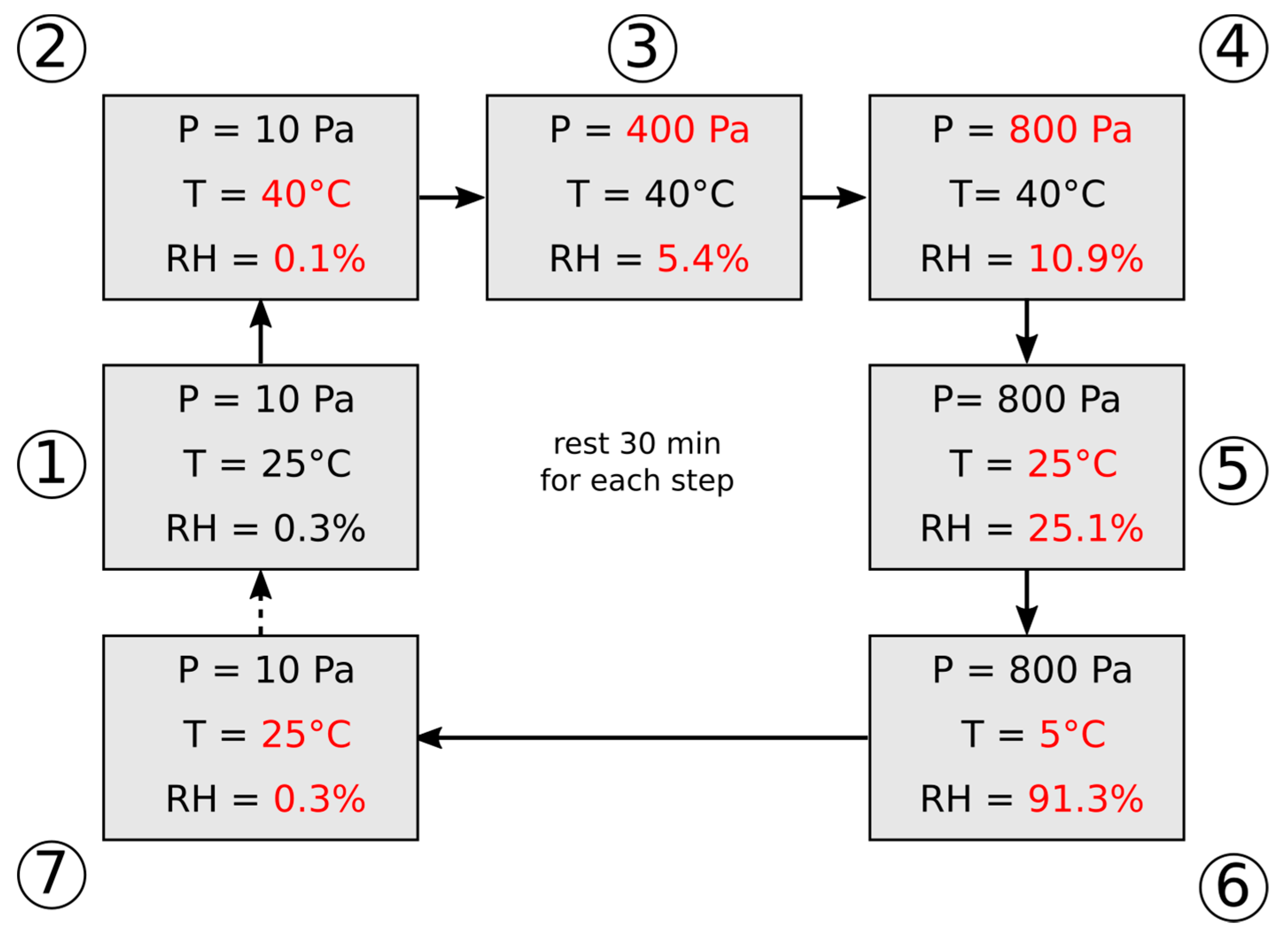
ESEM analysis was performed on produced foam, operating with an accelerating voltage of 8 kV, using isobaric conditions (10 Pa) from 25 to 40 °C, and at 40 °C, in controlled water vapor atmosphere, from 10 Pa to 800 Pa (0.1% to 10.9% of relative humidity), repeating the same conditions of dehydration (P = 10 Pa, T = 40 °C) and vice-versa for the sample hydration (P = 800 Pa, T = 5 °C). A scheme of the analysis set-up is reported in
Figure 1.
Experimental characterization of the achievable TES density was performed by means of a modified TG/DSC apparatus (Setaram Sensys Evo TG-DSC, SETARAM Instrumentation, Caluire, France), able to operate under pure water vapor conditions, i.e., like a closed sorption TES system. The main features of this apparatus are reported elsewhere [
24]. Different foam compositions were tested during a dehydration process from 30 °C up to 180 °C, with a heating rate of 5 K/min, under pure water vapor pressure of 2.33 kPa (corresponding to 20 °C in the evaporator). The obtained results were compared against pure bulk MgSO
4 7H
2O, to validate the improvement in the reaction kinetic as well as to calculate the achievable energy storage density by the synthesized foams.
3. Results and Discussion
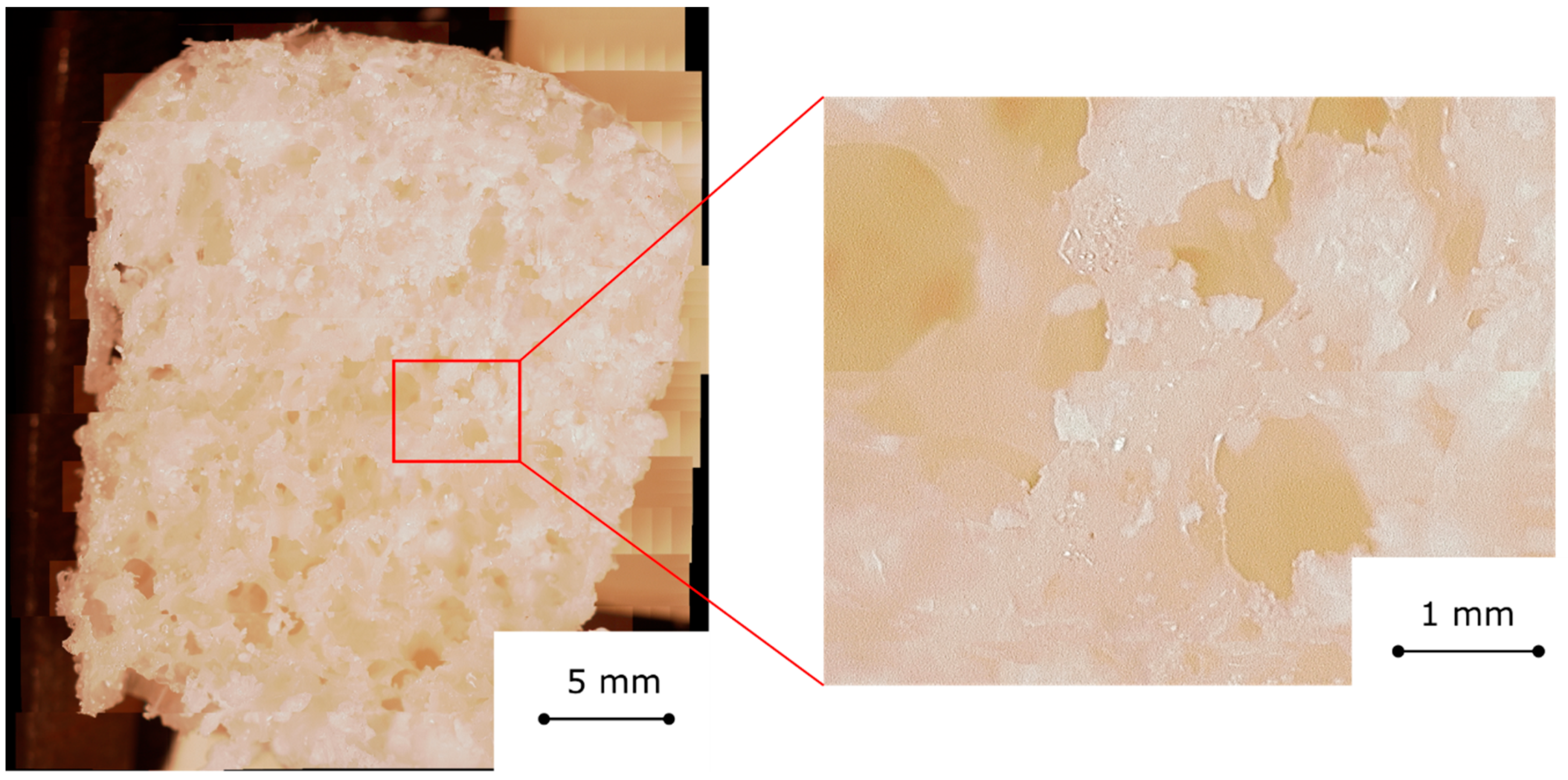
Figure 2 shows an optical image of the cross section of a FOAM60 sample. The cell structure is regular with interconnected bubbles [
22]. However, some local heterogeneities on the bubble size can be observed. At the foam borders some larger bubbles are clearly identifiable. The composite foam, although characterized by these local defects, can be considered almost homogeneous. Analyzing the details of
Figure 2 (left), it is possible to highlight the channel interconnection among bubbles. These channels act as preferential pathways for the water vapor diffusion toward the inner parts of the foams [
21], avoiding limiting mass diffusion phenomena usually observed on composite sorbent materials [
25]. Furthermore, the cell walls were thick enough to lead to a structurally stable morphology. Furthermore, the salt, 60 wt.%, is well embedded in the silicone matrix and no evident heterogeneities were observed.
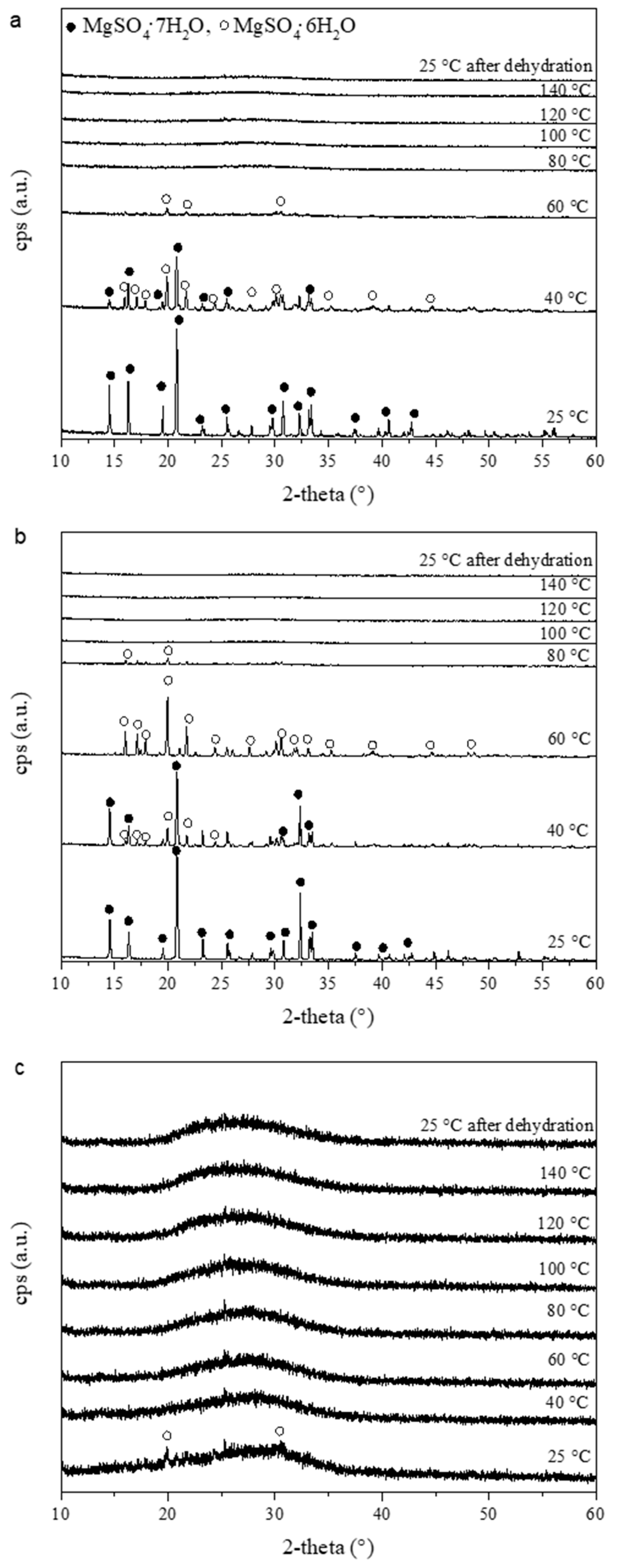
XRD patterns are shown in
Figure 3. XRD analysis was carried out on the salt, considering that the analysis on the composite foam is not possible without the necessary condition (flat surface) to carry out this type of structural analysis. To investigate the structural features of MgSO
4·7H
2O salt in various application conditions, XRD analysis was performed both in air, at different heating rates, and in vacuum which represents the condition applied during the following ESEM analysis. At 25 °C (
Figure 3a), the peaks of orthorhombic magnesium sulfate heptahydrate MgSO
4·7H
2O (2θ: 14.75°, 16.54°, 19.76°, 21.03°), in agreement with standard data (JCPDS: 04-009-8711), are present. The peaks appear sharp and narrow because of the high degree of crystallization of the MgSO
4·7H
2O. Increasing the temperature up to 40 °C, the peaks of hexahydrate monoclinic MgSO
4·6H
2O (2θ: 16.25°, 17.36°, 20.20°, 22.01°) in agreement with JCPDS 04-009-8713, appear. At 60 °C, only the latter phase is visible and an amorphous state forms, accordingly with van Essen et al. [
26]. Above 60 °C, no peaks can be observed, indicating that the amorphous phase remains stable also when the room temperature is reached again after the dehydration process.
It is worth noticing that by increasing the dehydration temperature rate from 1 °C/min to 10 °C/min, the structure of the salt loses its crystallinity later; in fact, in
Figure 3b at 80 °C, MgSO
4·6H
2O peaks are still visible, contrary to what is reported in
Figure 3a. The effect of the variable heating rate is the shift of the dehydration peaks to higher temperatures, suggesting that dehydration kinetics represent a critical issue to be assessed. High temperature increase rates result in a higher dehydration temperatures, owing to the poor salt thermal conductivity: at high temperature increase rates, there is insufficient time for the heat to be transmitted from the boundary surfaces to the bulk, leading to a delay in the dehydration step. The low heating rate leads to a sequence of equilibrium steps, favoring the dehydration phase achievement at lower temperatures [
27]. For these reasons, the first dehydration step (MgSO
4·7H
2O → MgSO
4−6H
2O + H
2O) is completed at 80 °C in
Figure 3a and it is not in
Figure 3b, where the amorphous phase, due to the second dehydration step (MgSO
4−6H
2O → MgSO
4−0.1H
2O + 5.9H
2O, according to [
28]), appears only at 100 °C. Indeed, as reported by Donkers et al. [
28], initially, the MgSO
4·7H
2O is a heptahydrate crystal without cracks. When the salt is heated up, the first occurring reaction is the dehydration towards the hexahydrate phase. This transformation is not completed as long as the temperature is below the triple point of the MgSO
4−H
2O phase diagram (48.5 °C). During the dehydration process, the crystal shrinks passing to the hexahydrate phase and a pseudomorphic structure in which a secondary porosity is formed, together with microcrystal voids. Increasing the temperature above 48.5 °C, the remaining heptahydrate is transformed to hexahydrate, and water vapor is produced. The vapor is not able to immediately and fully escape from the crystals because of the low diffusion or the lack of connection with the crystal surface. As a consequence, vapor pressure above the deliquescence point is generated, and a partial dissolution takes place, filling the crystal pores with MgSO
4 solution. When the water in the solution evaporates, hexahydrate crystals are formed, because of recrystallization from the saturated solution, blocking the surface. This blocking will occur when the evaporation is faster than the reorganization of the Mg
2+ and SO
42− ions. This behavior could be met when the heating rate is fast and the sample has insufficient time to reorganize its crystalline state.
As confirmation, when the dehydration is carried out under vacuum conditions (6 × 10
−2 mbar), the salt phase transition is strongly influenced, and the amorphous phase is present already at 25 °C (
Figure 3c), remaining stable until the maximum dehydration temperature is reached.
In TES materials, the hydration reaction is equally relevant in order to define the specific power and temperature that can be delivered to the load. Therefore, it is crucial to better assess the hydration/dehydration phenomena, in order to have useful information to design the TES composite material to reliably release the thermal heat stored during dehydration. As observed by XRD analysis, the hydration/dehydration processes in MgSO4·7H2O salt are influenced by kinetic phenomena, due to environmental boundary conditions (i.e., temperature, heating rate, atmosphere chamber status). In such a context, concerning the hydration/dehydration stages in the composite foam, the silicone matrix that embeds the filler could be a limiting factor. Therefore, a specific analysis, able to verify that the salt used as filler in the foam can effectively exchange water with the environment, is necessary to overcome this issue.
Furthermore, to investigate the foam behavior and understand if the siloxane presence has an effect on the salt performances in the hydration/dehydration phases, an environmental SEM analysis was conducted. By this approach, it is possible to visually evaluate the morphology modification during hydration and dehydration processes occurring in the salt hydrate embedded in the porous silicone matrix. Dehydration and hydration modifications were evaluated under varying temperature and water vapor pressure in the ranges of 5–40 °C and 10–800 Pa, respectively.
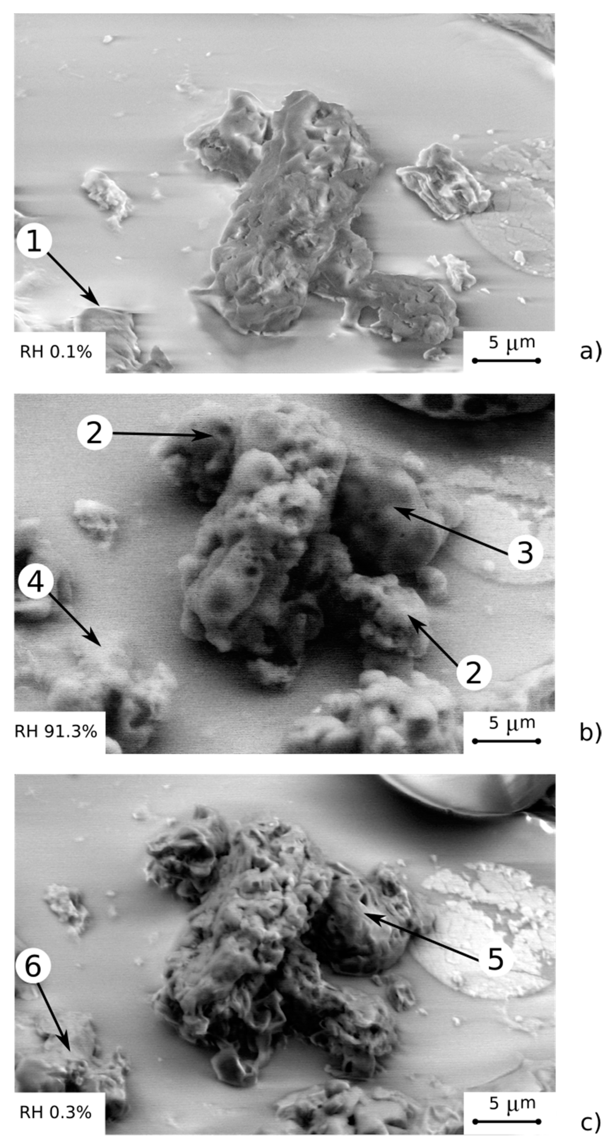
Figure 4 shows the results at reference pressure and temperature conditions in the climatic chamber of the microscope.
At first, a pressure of 10 Pa and a temperature of 40 °C (humidity 0.1%) were applied (
Figure 4a). The material was stored for 1 day in this condition in order to complete the dehydration process as confirmed by XRD analysis (
Figure 3c). The salt surface was rough with several asperities. This morphology is due to the dehydration process with subsequent volume reduction and favors the superficial formation of cavities and local asperities [
29]. Furthermore, in the bottom left corner of
Figure 4a (point 1), the presence of a further dehydrated salt agglomerate can be identified. This salt cluster is totally embedded in the silicone matrix, as identifiable by the smooth surface binder that acts as a covering layer.
Afterwards, by increasing the pressure up to 800 Pa, therefore increasing the relative humidity from 0.1% to 10.9%, no evidence of salt hydration was identified. Subsequently, by lowering the temperature to 5 °C and keeping the pressure constant at 800 Pa, the hydration process was stimulated, caused by the increase in humidity that reached 91%. In these conditions (
Figure 4b), the salt volume increase was evident due to the acquisition of the water molecules. This volume increase, however, does not involve the salt detachment from the matrix, avoiding salt loss during the hydration/dehydration process. At the same time, no cracks or local damaged areas on the silicones embedding matrix were evidenced. This result suggests that the hydration kinetics are quite slow, as reported in [
26]; in fact, the composite material does not undergo sudden transformations such as to cause superficial damages. The quite slow kinetics could be due to the transition from the amorphous phase (stable in dehydrated conditions, reported in XRD patterns in
Figure 3) to the crystalline phase (salt hydrate), which takes place during the hydration process. Nevertheless, the hydration/dehydration of magnesium sulfate hexahydrate depends on both temperature and water vapor pressure showing that the equilibrium between water vapor and the salt is bivariant [
11].
The volume increase in the salt hydrate is not regular and it is mainly located in edges and interstices of salt clusters (points 2 and 3 in
Figure 4b). This behavior can be explained, considering that these regions are directly located at the edges of the foamed particle, thus being near to the surface from where the vapor enters the foam particle. Therefore, the initial reaction will occur here, resulting in a pronounced volume increase; thus, the water agglomeration is favored. Further interesting information can be also acquired by analyzing the morphology modification induced on the crystal of salt embedded in the silicone matrix. In particular, at the bottom of the micrograph, the presence of a salt hydrate agglomerate can be highlighted (
Figure 4b, point 4). This provides a very important confirmation that salt crystals, although incorporated in the silicone matrix (as observed in
Figure 4a, point 1), are able to complete their hydration and dehydration process. The matrix, thanks to the high vapor permeability of the PDMS [
29], does not hinder the flow of water vapor and allows the interaction of the salt with the environment even if it is totally embedded in the silicone structure. Moreover, thanks to the flexibility of the silicone matrix, the volume expansion in the salt agglomerate induced by the hydration process does not imply the formation of defects or cracks on the cover layer of silicone. It deforms significantly without thereby implying a mechanical instability of the cover coating, offering an effective protective capability of the embedded salt hydrate. A detailed analysis of the hydration process will be deeply investigated in future work.
Finally, the characterization cycle was completed by bringing the environmental chamber down to 10 Pa and 25 °C at a humidity of 0.3% (as starting conditions). In these conditions, the material was suitably dehydrated (
Figure 4c), acquiring a structure morphology roughly compatible with the initial one (
Figure 4a). As a consequence, no damages due to trapped water occurred, as expected by the XRD analysis of pure salt, preserving the reusability of the foam. No defect or crack was identified, confirming the suitable applicability of this approach in order to obtain durable flexible porous composite sorbents.
However, at the end of the re-dehydration cycle, some local unevenness between the initial and the final phase of the cycle were identified. In particular, as evidenced by point 5 in
Figure 4c, an incomplete dehydration was observed, highlighting the presence of local areas where partial hydration in the salt is still noticeable. Similar considerations can be made by analyzing point 6 (with respect to point 1), where a slight increase in residual volume were observed due to an incomplete dehydration stage.
This ESEM analysis technique has certainly provided a valid approach with relevant potential in applied sciences and the research field. Nonetheless, it has defined new issues that must be deeply addressed. In such a context, further studies aimed at deepening the physical-morphological correlation of the process of dehydration and hydration of the salt inside the foam are necessary. Surely, an investigation aimed at assessing the process evolution during time can also indirectly provide useful information on the role of kinetic phenomena in hydration/dehydration processes. In fact, material stability at long ageing cycles is a relevant issue that will be addressed in order to better quantify the performance efficiency of these composite materials for thermochemical energy storage applications.
4. Energy Storage Density
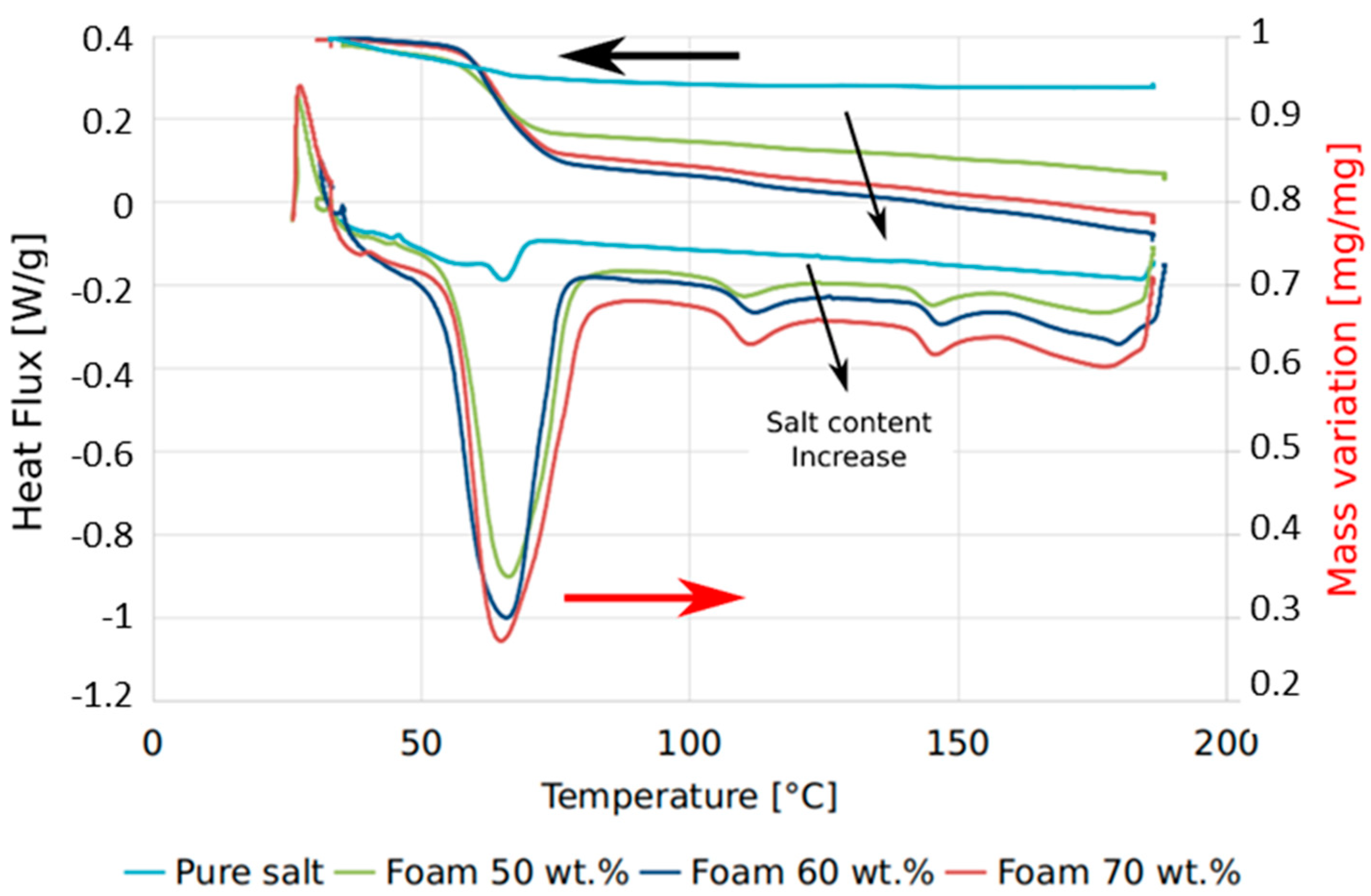
In order to evaluate the improvement of the reaction kinetics achievable by the foamed structure compared to the bulk MgSO4 7H2O, as well as to evaluate the TES storage density of the investigated materials, TG/DSC analyses under pure water vapor conditions during a dehydration process were performed for the pure salt, FOAM50, FOAM60, and FOAM70 samples.
Figure 5 compares the DSC thermograms and the TG evolution obtained under the mentioned working conditions. The first observation is that the three foamed samples clearly show desorption peaks, while the pure salt only shows a very small desorption peak. This behavior can be attributed to a kinetic hindering the desorption process due to the bulk state of the MgSO
4. This is already a positive feature confirming the usefulness of the proposed approach to overcome issues related to the pure salts. Analyzing the foamed samples, it is evident that in the investigated temperature range, there are three distinct reactions, whose peak temperatures can be identified at about 65 °C, 111 °C, and 146 °C, respectively. Nevertheless, about 90% of the overall energy is stored during the first reaction, thus confirming the applicability of this material in a low/medium temperature range. Finally, as expected, FOAM70 shows wider peaks compared to FOAM60 and FOAM50, since the heat flow is normalized over the composite mass. Accordingly, the role of the active material (i.e., the salt) is more evident for the samples with higher salt content. In order to analyze the actual energy associated with the process, the integration of each thermogram was performed.
Table 1 summarizes the results obtained by the data analysis. At first, the actual salt content in the three foamed samples was evaluated, by comparing the theoretical and the actual mass loss encountered during the test. As it can be highlighted, in both cases, the amount of salt inside the porous structure was lower than the theoretical one. There was a discrepancy of about 16–18% compared to the nominal content. This could be due to the sample handling process, during which the salt deposited close to the surface, so not very well embedded inside the foam, may be partially lost. Nevertheless, the achieved sorption enthalpy for the whole temperature range, 1012.8 J/g and 786.2 J/g, for FOAM70 and FOAM50, respectively, are quite attractive and in line with the data reported in the literature in [
30]. The FOAM60 batch showed intermediate values compared to the other composite foams. As already mentioned before, most of the energy associated with the process is released during the first stage, where, according to [
30], the equivalent of 5.9 water molecules are released.
Referring to the measured density of the samples, which is in the range of 330–470 kg/m3 (with highest density for FOAM70 and lowest one for FOAM50), it was also possible to evaluate the achievable energy density considering a low/medium charging temperature (e.g., around 100 °C), thus involving only the first reaction occurring. The calculated volumetric energy densities evidenced that the highest value is obtained for FOAM70 where a volumetric energy density equal to 0.48 GJ/m3 was observed. The foams with lower salt contents highlighted a less effective volumetric energy density. In particular, FOAM50 showed a value of 0.26 GJ/m3.
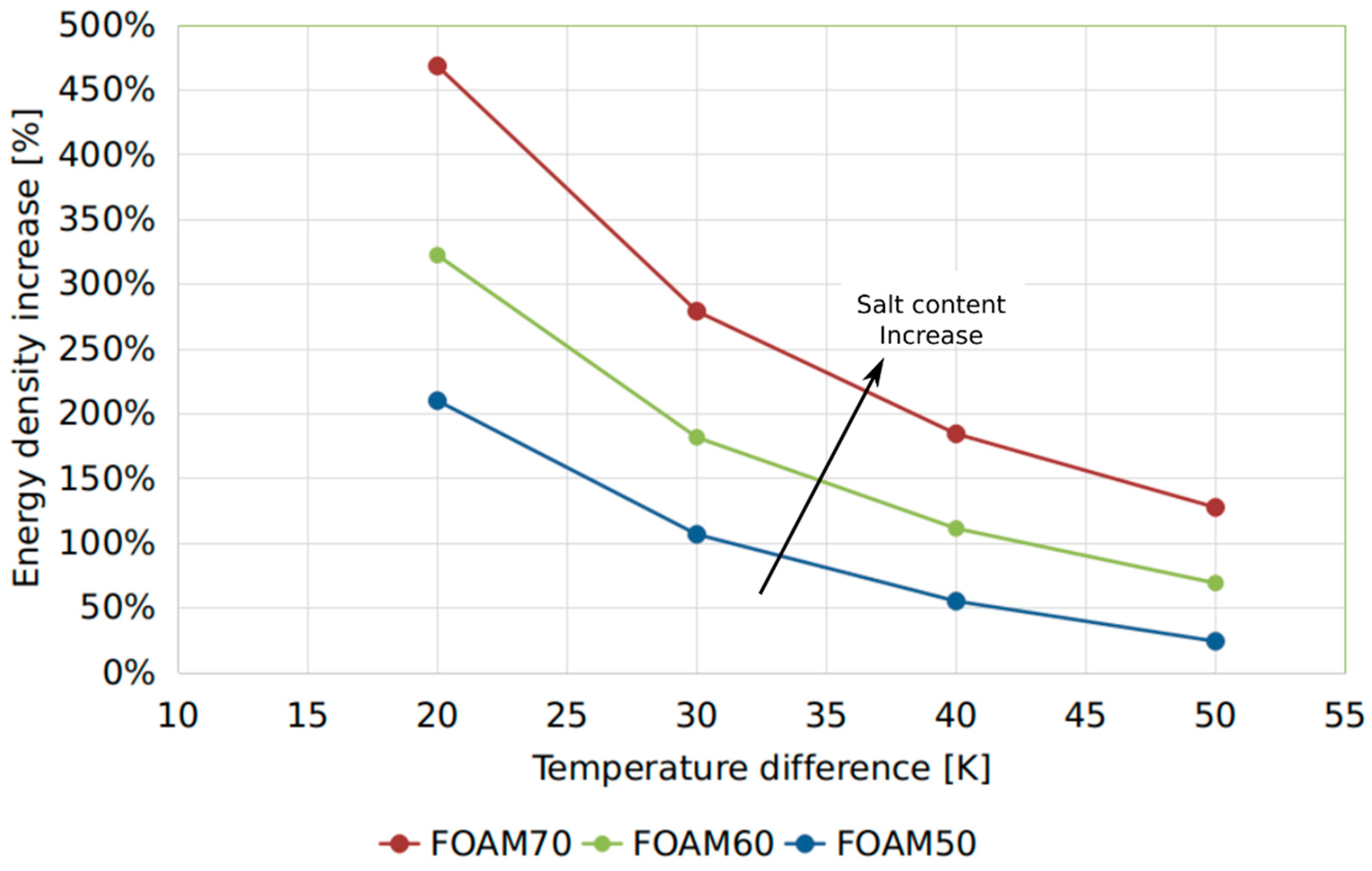
The achievable TES density of the developed foams was compared to the reference sensible water storage.
Figure 6 reports the energy density increase of the foamed samples against the sensible water as a function of the temperature difference under which the sensible TES can operate. For very small temperature ranges, i.e., 20 and 30 K, the increase reached up to 470%. These operating conditions can be assumed when a low temperature floor heating system is employed. For typical high temperature space heating distribution systems and domestic hot water production, an increase ranging between 50% and 150% can achieved, further confirming the interesting features of these materials.
However, further development scenarios can be identified by optimizing the different foam formulations in order to obtain a denser macro-porous structure, characterized by interconnected pores and a very small pore size. As highlighted in [
26], related to the morphological study of zeolite-filled silicone foams, the authors obtained composite foams with about 30% of void volume. Even in this morphological configuration, an effective vapor flow through the foam walls was verified. Based on these considerations, in hydrated salt-based composite foams, this condition would induce an increase of two or three times the energy density depending on the salt content in the composite foam.

 ,
, 


