Article

Active Load-Sensitive Electro-Hydrostatic Actuator for More Electric Aircraft

1
School of Automation Science and Electrical Engineering, Beihang University, Beijing 100191, China
2
Science and Technology on Aircraft Control Laboratory, Beihang University, Beijing 100191, China
3
Ningbo Institute of Technology, Beihang University, Ningbo 315800, China
*
Author to whom correspondence should be addressed.
Appl. Sci. 2020, 10(19), 6978; https://doi.org/10.3390/app10196978
Submission received: 4 September 2020 / Revised: 27 September 2020 / Accepted: 2 October 2020 / Published: 6 October 2020
(This article belongs to the Special Issue Advanced Materials and Technologies for Aerospace Applications)

Abstract

:
In the flight control system, using an electro-hydrostatic actuator (EHA) instead of the currently used relatively mature electro-hydraulic valve-controlled actuator, there are three prevailing concerns, namely heating, size, and stiffness. This paper proposes a novel principle EHA, called active load-sensitive EHA (ALS-EHA), which can actively realize the adaptive adjustment of pump displacement with load pressure. Its principle analysis and mathematical modeling based on the direct load-sensitive EHA (DLS-EHA) configuration is done to obtain the relationship between motor current and hydraulic reduction ratio. Then, its stiffness characteristics are analyzed, especially the influence of hydraulic reduction ratio on impedance at low frequencies combined with investigating the power matching of ALS-EHA. A comparative experiment between the developed ALS-EHA and the EHA with fixed pump displacement and variable motor speed (EHA-FPVM) was carried out. The results reveal that the proposed ALS-EHA can reduce the motor heating and its displacement tracking error is smaller near zero speed owing to its higher impedance from the lower hydraulic reduction ratio under heavy load conditions.

1. Introduction

As the “skeleton” and “muscle” of the aircraft structure, the flight control actuation system plays an irreplaceable role in its structure [1,2,3]. At present, most civil and military aircraft use a central hydraulic oil source for centralized fluid supply, adopt engine-driven pumps to provide high pressure, and employ servo valves to implement servo control of the rudder surface and landing gear through the throttle principle [2,3,4]. This method has mature technology and good dynamic performance, but low efficiency and complex pipeline layout problems have become the main factors restricting the further improvement of aircraft performance [5]. In modern battlefields, it is increasingly demanding for fighter jets maneuverability, energy efficiency, fuselage layout, survivability, etc., and this raises a higher challenge requirement for flight control actuator system as one of the key components of airborne electromechanical systems and flight control systems [6]. With the exploded appearance and swift advancement of more/all-electric-aircraft (MEA/AEA), a power-by-wire actuation system has become main steam behind aviation progression, which exterminates the desideratum for the aircraft’s classical hydraulic system and only requires a variety of energy procreation (electric power) resulting in simplifying secondary energy systems, so it brings about more advanced reliability and lowers design and maintenance costs [7,8,9].
EHA is an attractive category of power by wire, and it utilizes a hydraulic pump as a transmission reducer to transform the motor’s rotational motion into the linear motion of the actuator’s output with other components, such as oil supply circuit, bypass valve and safety valve, as shown in Figure 1. Hydraulic coupling allows greater flexibility in integrated design of EHA components. The installing position and direction of the motor and pump relative to the actuator can be flexibly adjusted to satisfy the demand for integrated volume size. This is a superiority of EHA compared to another candidate power-by-wire electromechanical actuator (EMA). The installing position and direction of motor and gear of EMA do not allow to be dexterously shifted [10]. EHA can regulate the transmission ratio by controlling the pump displacement. Adjustable transmission ratio can increase the actuator stiffness, reduce integration volume, and decrease system heating. In the flight control system, using EHAs instead of the currently used relatively mature electro-hydraulic valve-controlled actuators, there are three prevailing concerns, namely heating, size, and stiffness [11]. So far, the average efficiency of the EHA applied in the aviation field is about 35%, and the bandwidth is generally about 7Hz [12].
EHA heating is an imperative dilemma. In a central hydraulic pump system, heat loss is transferred from the actuator to the central heat exchanger via hydraulic fluid, however EHA has no fluid exchange, so a separate heat exchanger mounted on the EHA or a fluid radiator added to the aircraft is required for cooling, which will greatly increase the difficulty for the confined space to package the actuator neighboring the control surface. An important source of heat loss is the nature of the aerodynamic load. The operating conditions of EHA include forward load and reverse load. When EHA operates under aiding load condition, the aerodynamic load works on the actuator, reversely driving the pump to rotate the motor as generator. The aiding-load energy is converted into electric energy which moves in the form of a current in the system. Another vital reason for EHA heating is the low efficiency of the system components. The most remarkable one is the motor copper loss. The motor torque is proportional to its current. The torque required to balance the load is proportional to the pump displacement which necessarily matches the motor speed and the actuator piston area to meet the actuator speed. In short, motor is the main heat source of EHA, e.g., an experimental result shown in Figure 2. Under the condition of 4t with load and continuous working for seven minutes, the surface temperature of the motor rises from 29.5 °C to 51.6 °C, and the hydraulic-part temperature remained essentially unchanged. The problem of motor heating is the main reason affecting the EHA widespread application [13]. The energy loss of the motor is mostly dissipated through heat generation in the form of copper and iron losses. Meanwhile, the dynamic performance of the system at high temperatures will be affected to some extent. If the motor heating can be reduced, it is of great significance for EHA to improve the efficiency, dynamics and reliability, as well as increase continuous the working time and lifetime [14].
The idea of solving the problem of motor heating- is to popularly use high-speed motor and high-pressure system for the EHA-FPVM. For example, the EHA system designed by SAFRAN in France and UTC-Goodrich in the United States uses 20,000 rmp motors and 35MPa hydraulic systems. The system achieved a level of 16,000 rpm and a peak pressure of 35 MPa. The method of high pressure and high speed can expand the speed regulation range of the motor and enable the motor to work in the high efficiency area [15]. This method is currently very popular because of its simple structure and control, but this fixed displacement architecture cannot achieve the optimal power matching of motor and pump, where the power of the selected motor is the larger, which is disadvantageous for high power density requirements. The EHA with variable pump displacement and variable motor speed (EHA-VPVM) has become a popular concern, because its two control variables can well achieve the motor-pump power matching and reduce the motor heating, as well as improve the EHA stiffness [16]. The general variable displacement mechanism requires an open valve-controlled cylinder with additional oil supply pressure to alter the pump displacement through varying the tilt angle of the swash plate [17]. The principle structure has fast response but increases the cost and complexity of the system. Reference [18] proposed a new type of electric variable mechanism composed of a direct current (DC) servo motor and related transmissions (gearbox + sector gear). The purpose is to simplify the structure of the variable mechanism, reduce hydraulic faults and improve maintainability. The meshing between gears inevitably has problems such as tooth-side clearance, inter-tooth lubrication media, and various transmission errors (including various manufacturing errors, installation errors, thermal deformation, wear, etc.). These coupling effects have a certain degree of influence on the performance of the electric variable mechanism. Chao etc. designed a load-sensing pump based on a variable displacement architecture to reduce EHA heat generation in [19]. Jiao advanced the principle of direct load-sensitive EHA (DLS-EHA) based on load-sensing pumps [20]. The DLS-EHA automatically adjusts the pump displacement through the load pressure without the need for an additional power source, which can decrease the motor heating and achieve the motor-pump power matching to a certain extent. However, the back pressure spring of the variable mechanism must be selected according to the maximum load pressure to ensure that the variable mechanism is sufficiently rigid to stabilize the system. A large back pressure spring stiffness results in a low rate of change in displacement with load pressure. DLS-EHA does not give consideration to the dynamics and the efficiency of the system, and the variable characteristic is a constant value making it difficult to achieve optimal matching.
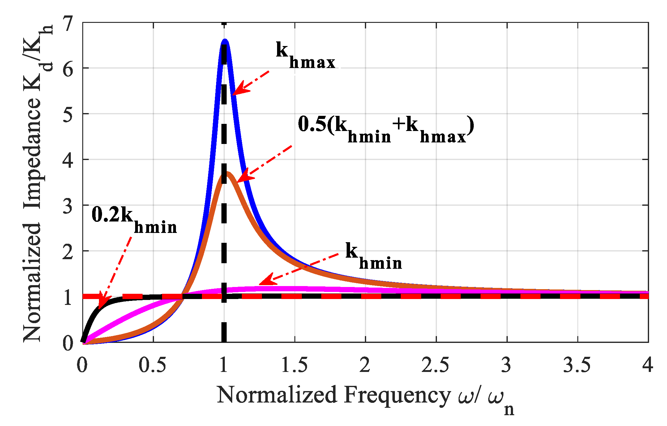
Stiffness is an index to measure the effect on the system output when the load force changes. Dynamic stiffness describes the changing law of stiffness in the dynamic process. The stiffness characteristics of the flight control actuation system can be divided into three parts according to frequency: (1) Within the bandwidth of the closed control system, the stiffness can be controlled due to the controller’ function that can guarantee the actuator output track the input. (2) At the reversal point of the frequency, the controller’s adjustment effect is positive feedback to cause the actuator output to alter greatly, so the system stiffness is the lowest. (3) Since it is too late for the actuator to respond to the disturbance at high frequencies, its stiffness is related to the passive components of the system. EHA is developed as a potential substitute for the valve-control actuation system in the flight control actuation system, its stiffness is also a major consideration [21,22,23]. The stiffness characteristics of EHA and the valve-controlled actuator are distinct, especially at direct current and low frequencies. Regarding the stiffness of the valve-controlled actuator, the valve opening is not affected by the load pressure perturbance that keeps closed and its two chambers hold blocked. The impedance of the valve-controlled actuator is governed by the hydraulic stiffness of the two choked chambers of the actuator, where the enclosed oil has ability to counteract the load. If it is a double-rod actuator (the pressure goes up on one side of the piston and lowers on the other when the actuator is loaded), the impedance at the middle of the actuator stroke is 4 β A a / L (where β is elastic modulus of oil, while A a and L represent the area and stroke of the cylinder respectively), however, the stiffness of the single active side actuator is half of the former’s. Thus, stiffness is related to piston displacement. When the dynamic side has the shortest liquid column length, the stiffness is the largest, and when the high pressure side has the longest liquid column length, the stiffness is the smallest at the other end of the cylinder. The minimum stiffness of the single-rod actuator is a quarter of the one of the double-rod actuators. Compared with the valve-controlled actuator, in fact, the EHA has no real impedance, since EHA is a combination of electric and hydraulic and its two chambers cannot be obstructed, considering the increasing load pressure can drive the motor rotation back. Therefore, the stiffness of EHA depends on the hydraulic stiffness of the actuator and the electrical stiffness of the motor. Load disturbance will drive the motor to rotate and cause the actuator output displacement to vary, so it is necessary to improve the electrical stiffness. The displacement of EHA-FPVM cannot be adjusted, so the disturbance torque of the motor cannot be regulated, so its electrical stiffness is constant. For the new configuration of ALS-EHA mentioned in this paper, the displacement can be actively shifted, so the disturbance torque to the motor can also be lowered, and the stiffness of the new configuration can also be enhanced.
The structure for the whole paper is arranged as follows: Section 2 mainly presents the research on the principle analysis and mathematical modeling of ALS-EHA based on DLS-EHA configuration. Section 3 mainly studies the dynamic stiffness of ALS-EHA and the relationship between the stiffness at low frequencies and the hydraulic transmission ratio. 
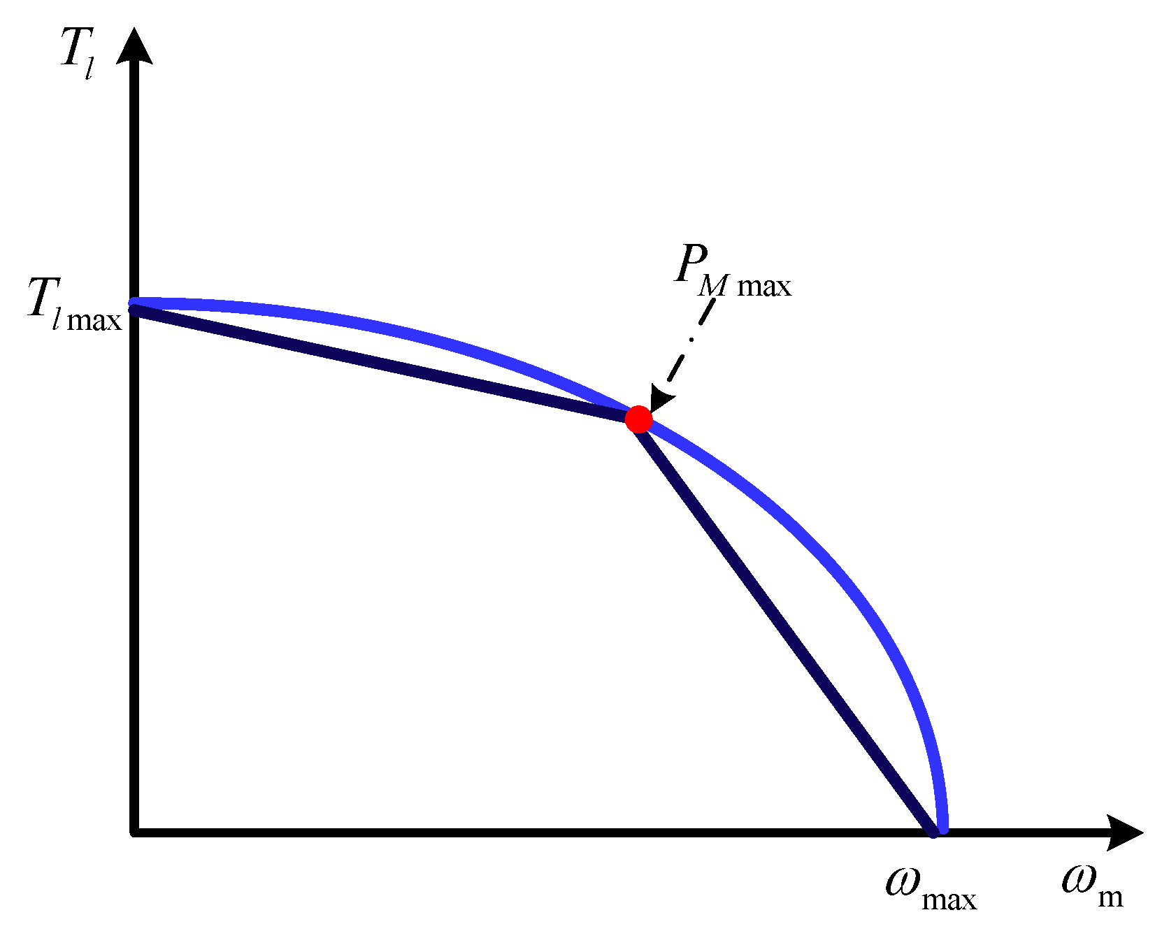
Section 4 mainly compares the power matching of ALS-EHA with that of EHA-FPVM, and then further analyzes the former matching rule. In Section 5, the experiments of EHA-FPVM and ALS-EHA are compared to verify the performance of the latter, and final conclusions are presented.

2. The Principle Analysis and Modeling for ALS-EHA

In order to solve the heating problem of the motor, our research group proposed a novel EHA configuration based on load-sensing technology. In this part, the principle of load sensitivity is first analyzed. Based the simple structure of DLS-EHA, the ALS-EHA which is mainly studied in this paper is derived and the load sensitive characteristics are studied by means of mathematical modeling.

2.1. The Load Sensing Principle Description

Load-sensitive EHA includes two types: DLS-EHA and ALS-EHA.
The DLS-EHA schematic is displayed in Figure 3. The load-sensitive servo mechanism uses a shuttle valve to guide the pressure of the high-pressure chamber of the EHA to the swash plate mechanism of the variable pump. Thus, the function of passively regulating the displacement with the load is realized. Adding a damping hole between the valve port and the variable mechanism can effectively alleviate the fluctuation of system performance caused by load shock.
According to the principle of direct load sensitivity, it can be known that, when the external load is large, the pressure introduced into the pump variable mechanism increases, so the displacement of the pump decreases.
According to the analysis in Section 2.2, it can be known that the motor current can be effectually alleviated in the stalled condition; in the non-stalled condition, the motor current can be validly subsided within a certain adjustment range. Therefore, the DLS-EHA can effectively reduce the copper loss of the motor within a certain operating range. However, because the pump displacement is passively adjusted with the load, the system stiffness is reduced, resulting in a significant reduction in system dynamic performance under heavy load conditions. The existing improvement method is to appropriately increase the spring stiffness of the variable displacement mechanism of the plunger pump, thereby which is in favor of increasing the system stiffness and reducing the gradient of displacement with load pressure, but will increase the loss of the motor at the same time. In addition, the view that the smaller the pump displacement is regulated, the less the heat is generated by the motor is still to be further verified: According to the analysis in Section 2.2, it can be known that the conclusion that the smaller the displacement is, the less heat the motor generates is a one-sided and inaccurate conclusion. Under medium/high speed and heavy load conditions, it may be happened that within the displacement adjustment range, the motor heat generation will first fall and then rise as the pump displacement drops. Under these conditions, the use of DLS-EHA may even outweigh the benefits.
So as to deal with the direct discrepancy between dynamic performance and efficiency in DLS-EHA, a novel active load sensitive technology is proposed. The ALS-EHA is based on the DLS-EHA, and a pressure follow valve (PFV) that can actively adjust the pressure enforcing the variable pump swash plate is added. The schematic of the ALS-EHA is shown in Figure 4.
The principle of the ALS-EHA is that the load pressure is imported to the PFV through the shuttle valve and then the valve outlet pressure can be controlled at range of 0 to the maximum load pressure by the external control signals, which is connected to the swashplate variable mechanism of the pump. It can be known that by controlling the PFV input current, the pump swashplate angle can be adjusted between the maximum and the value corresponding to the load pressure.
Since the pump displacement can be actively controlled in the ALS-EHA, by designing a desirable control law, it can effectively avoid the problem that the decrement in displacement leads to the increment in motor heating and the decrease in dynamic. Meanwhile, the system needs better tracking performance and the external load is relatively large, the motor efficiency can be sacrificed to ensure the dynamic performance. Therefore, under the trade-off, the ALS-EHA is relatively superior in performance.
Compared with the conventional EHA-VPVM, the ALS-EHA need not have a separate power source, and can realize the active adaptive control on displacement through a PFV, which has the advantages of small size, light weight, and simple structure.

2.2. Modeling Investigation

2.2.1. Motor Pump Main Loop

For a brushless DC motor, the torque dynamics balance equation is:
T m = K t i m = J m ω ˙ m + B m ω m + T l
where K t is the motor torque constant; J m , B m is the total inertia moment and damping coefficient equivalent to the motor shaft, respectively; T l is the motor output torque (pump input torque), which drives the pump to rotate; i m , T m , ω m represent motor current, electromagnetic torque, and rotational speed, respectively.
Without considering leakage, the system flow equation is shown as follow:
Q l = A a v a = D p ω m
where Q l is load flow of the system; A a , v a represent the piston area and speed of the cylinder, respectively; D p is pump displacement. The equation of pump input torque is obtained from load pressure and displacement:
T l = D p P l
where P l is load pressure of the system.
(1) In the stalling condition, combining formulas (1) and (3), the follow equation can be gotten
K t i m = D p P l
At this time, the motor current is proportional to the pump displacement, that is, the larger the displacement, the more heat the motor generates in the stall condition.
(2) In non-stalling mode, for purpose of simplifying the calculation, it is assumed that the angular acceleration of the motor is known. Equation (5) can be obtained by combining formulas (1) and (3).
K t i m = J m A a x ˙ a D ˙ p D p 2 + ( J m A a x ¨ a + B m A a x ˙ a D p + D p P l )
where x a is actuator displacement. Observing formula (5), the part in parentheses shows a logarithmic function relationship. It can be seen that, in a certain range under this operating condition, the motor current and the pump displacement are approximately a logarithmic function relationship, i.e., the current gradually decreases to minimum first and then increases as the displacement goes down.
The pump in EHA is equivalent to a reducer without considering pump loss, and the hydraulic reduction ratio is defined as k h = v a / ω m . Under the law of conservation of power, T l ω m = F l v a , combined T l = D p P l with F l = P l A a , we get k h = v a / ω m = T l / F l = D p P l / P l A a = D p / A a which is the ratio of the pump displacement to the actuator area. Formula (5) can be changed as follows:
K t i m = J m x ˙ a k ˙ h k h 2 + ( J m x ¨ a + B m x ˙ a k h + k h A a P l )
where F l is the output force (load force) of the actuator. Formula (6) shows that the hydraulic reduction ratio can be controlled by adjusting pump displacement to minimize motor current.
In addition, if the iron loss of the motor and various efficiency losses of the pump are comprehensively considered, the relationship between the total heat generation of the motor and the displacement of the pump is complicated, and further modeling research is needed. For two control variable ALS-EHA, motor velocity and pump displacement can be actively controlled. Therefore, by designing a reasonable control law, e.g., the fuzzy neural control method of lifting system dynamics as proposed in Ref. [24], it is possible to effectively reduce the motor current and lower the motor heating. This is the basic idea of power matching design.

2.2.2. Load-Sensitive Loop

Load-sensitive loop consists of pump variable mechanism and PFV, of which output pressure and flow act on the variable hydraulic cylinder to move its piston to push the swash plate to adjust its inclination as shown in Figure 5. The loads acting on the swash plate mainly include the spring pre-tightening force, the hydraulic load, and the inertia force.
1. The force balance equation of the variable piston is as follows:
P A A 1 = m v t x ¨ v + B v c x ˙ v + K x v + F 0 + F v
where mvt indicates the total mass of the piston and load, Bvc represents viscous damping coefficient, K is load spring stiffness, F 0 is spring preload, Fv is variable piston force acting on the swash plate, P A is output pressure of valve, A 1 , x v denote the velocity and the area of the piston, respectively.
2. Moment balance equation of swash plate:
L f F v = J s γ ¨ + B s γ ˙ + M T + M 0
where Lf denotes the arm of the variable piston force acting on swash plate, Js denotes moment of inertia of swash plate, Bs denotes viscous damping coefficient, MT, M0 denote the torque generated by the hydraulic load and spring preload acting on the swash plate. γ denotes swash plate inclination.
Remark 1.
The average value of the resultant moment of the force acting on the swash plate at high speed is basically 0, so it can be assumed M T + M 0 = 0 during analysis.
So, formula (8) can be simplified as:
L f F v = J s γ ¨ + B s γ ˙
The relationship between the inclination angle of the variable pump swash plate and the displacement of the variable piston is as follows:
x v = L f tan γ
Since γ is generally small in practice, assuming that it can be approximated as
γ = x v L f
The following formula can be derived from Equations (8) to (12)
P A A v = M d x ¨ v + B d x ˙ v + K x v + F 0
where M d = m t + J L f 2 , B d = B c + B L f 2 are the total equivalent inertia and damping of load sensitive loop, respectively.
According to the relationship between the tilt angle of the swash plate and the displacement, the displacement can be expressed as follows
D p = ( 1 γ γ max ) D p max = D p max K p γ
where γ max , D p max represent the swash plate inclination maximum and displacement maximum, respectively; K p = D p max / γ max is pump displacement gain. Combining formulas (11) to (13) gives:
P A A 1 = M d L f K p D ¨ p B d L f K p D ˙ p K L f ( D p D p max ) K p + F 0 = M d L f A a K p k ¨ h B d L f A a K p k ˙ h K L f A a K p k h + K L f D p max K p + F 0 = M d E k ¨ h + B d E k ˙ h + K E k h + K L f D p max K p + F 0
where E is equal to L f A a K p . Formula (14) shows that the load sensitive loop is a spring mass damping system. Since the inertia of load sensitive loop is very small, it can be simplified as elastic link to analyze the load sensitive characteristic.
The DLS characteristics derived from formula (14) after simplification are shown in the Figure 6 below [19].
D = { D p max f o r 0 P l P 0 D p max D p max D p min P l max P 0 ( P l P 0 ) f o r P 0 P l P l max
where D p max , D p min represent the maximum and minimum displacement of pump, P l max , P 0 are the maximum load pressure and the swash plate pre-tightening pressure.
According to the [21], the formula for calculating the stiffness of the back pressure spring of the variable mechanism is shown below:
K = P l max P 0 D max D min A v K p L f = G P l max P 0 D max D min
where G = A v K p L f . By combining formulas (15) and (16), the following equation can be derived.
D = { D p max f o r 0 P l P 0 D p max G K ( P l P 0 ) f o r P 0 P l P l max
As shown in Equation (16), the stiffness of the compressed spring of the variable mechanism for DLS-EHA must be selected according to the maximum load pressure, therefore, K should be selected large enough to ensure the stability of the system. According to Figure 6 and Equation (17), it can be concluded that the gradient of displacement to load pressure is a constant and cannot be adjusted which cannot guarantee that under all load conditions, the system performance such as efficiency and dynamics are optimal. The load-sensitive circuit has passive attribute.
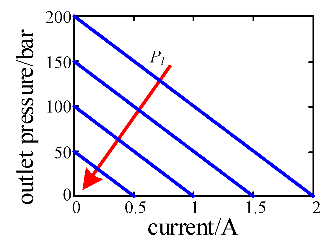
PFV has the same principle as the proportional pressure reducing valve, of which output pressure can be linearly controlled by actively controlling valve input current. The PFV characteristics are shown below Figure 7. So, it can be modeled as follows
P A = P l K v i v
where K v , i v are pressure gain and input current of the valve, respectively.
Load sensitivity is expressed below:
α = P A P l
Let k α be equal to 1 α .
Equation (14) can be written as:
P A = P l ( 1 k α )
Remark 2.
When the input pressure Pl is constant, the output pressure is a linear function of the input current. As the input current grows, the output pressure declines. Pl affects the gradient value of the output.
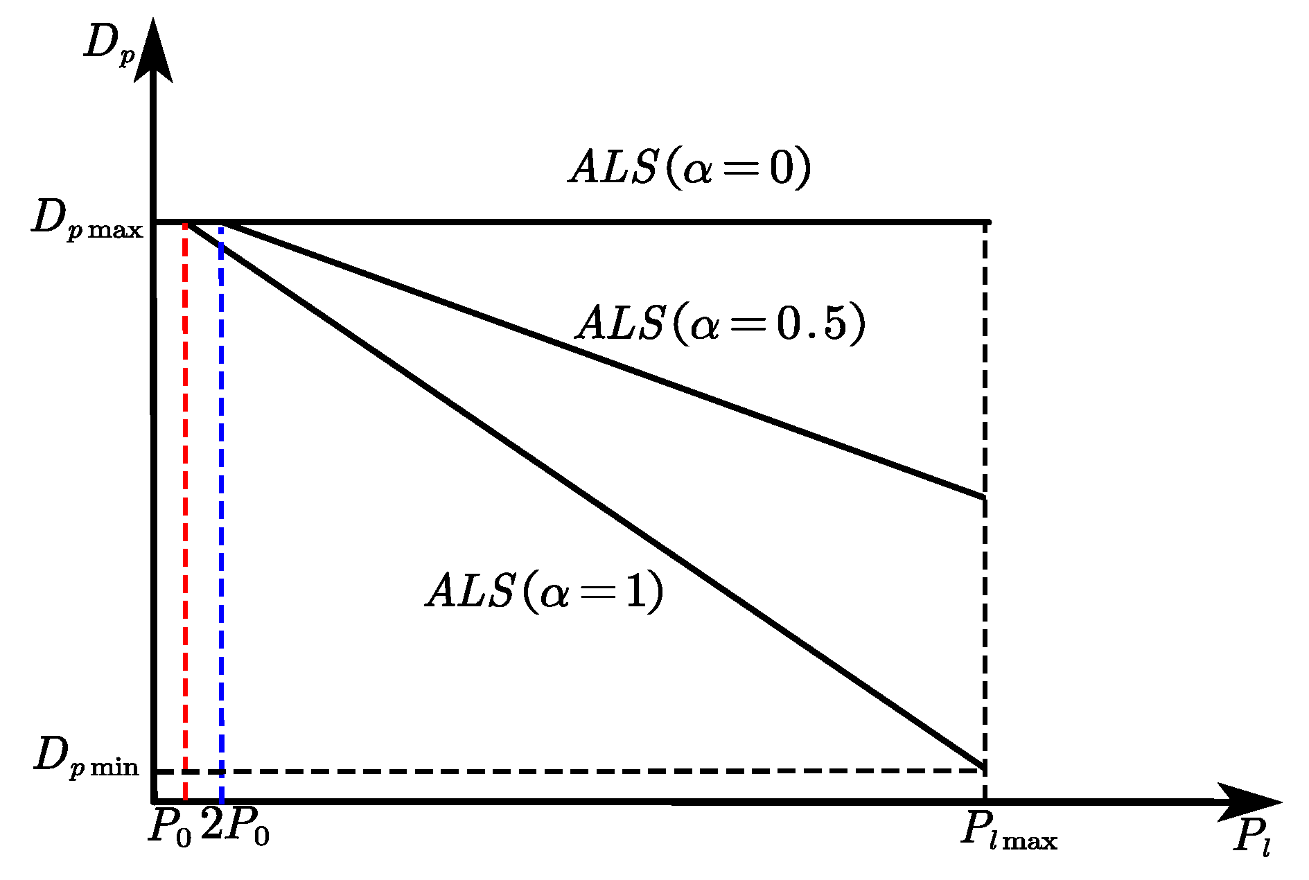
Based on the ALS principle combined with the characteristics of the DLS variables, we can draw the relationship of the characteristics of the ALS variables as shown follows:
D = { D p max f o r 0 α P l P 0 D p max G K ( α P l P 0 ) f o r P 0 α P l P l P l max
As shown in Figure 8, a PFV capable of active control is added to the original DLS loop. The stiffness of the spring is still selected according to the DLS. It can be concluded that the gradient of displacement to load pressure varies with the load sensitive, that is, it can be actively adjusted. The greater the load sensitivity is, the greater the gradient is. We can also see that the EHA-FPVM and the DLS-EHA are two boundaries of active load sensitivity. The former has a load sensitivity of 0 and the latter is 1.
In the ALS loop, we choose the stiffness of the back pressure spring according to the following formula (22).
K = α P l max P 0 D max D min A v K p L f = G α P l max P 0 D max D min
It can be known from the formula 22 that the spring stiffness for ALS-EHA can be less than that for DLS-EHA which is conducive to increasing the adjustment range and is beneficial to the improvement of system performance and the flexibility of control. After the compressed spring stiffness is corrected, the characteristic curve for ALS-EHA is shown in Figure 9 below.

3. Stiffness Analysis for ALS-EHA

This section mainly describes the concept of the dynamic stiffness of EHA, and on this basis builds the ALS-EHA stiffness equivalent model, then derives its complex frequency domain transfer function through its mathematical model, and deeply analyzes its frequency characteristics and studies the influence of hydraulic gear ratio on stiffness. Finally, simple method is proposed to increase damping.

3.1. Description and Equivalent Model of Stiffness

The differential pressure of the pump is caused by the motor rotating freely as the load pressure increases. Although EHA owns no real stiffness, it can produce a resistance to dynamic load. The impedance results from the inertia and damping of the motor. This impedance can be equivalent to a spring mass damping series model as shown in Figure 10. The spring is equivalent to a liquid column, and the mass M and damping C are equivalent to the inertia J m and damping B m of the rotating components for motor-pump set on the output side of the actuator. For ALS-EHA, M and C can be actively adjusted through a load-sensitive loop.
With the mathematical modeling of Figure 10, assuming an elastic load, according to Newton’s second law of motion, dynamic equations can be obtained as Equation (23).
{ F l = K h ( x a x 1 ) K h ( x a x 1 ) = M x ¨ 1 + C x ˙ 1
where M a is the actuator-load total mass M, C are respectively the equivalent mass and damping which are equal to the motor-pump rotational inertia and damping divided by k h squared, x 1 is the displacement of the equivalent mass, and K h is the hydraulic stiffness in the cylinder. The transfer function of the system can be obtained according to formula (23).
x a ( s ) F l ( s ) = M s 2 + C s + K h s ( M s + C ) K h

3.2. Frequency Characteristics of Stiffness

For a sinusoidal disturbance load with frequency w , the magnitude of the transfer function is.
| x a ( j w ) F l ( j w ) | = [ ( ( M w ) 2 M K h + C 2 ) 2 w 2 + ( C K h ) 2 ] 1 2 w K h ( ( M w ) 2 + C 2 )
Equation (25) represents that at low frequencies band, as the frequency w reaches zero (DC input), the displacement x a tends to infinity. This means that, in the absence of control, the load will be able to rotate the motor freely until the actuator reaches either end of the hydraulic cylinder. At high frequencies, the magnitude | x a ( j w ) / F l ( j w ) | decreases to 1 / K h as frequency w increases. This is because the equivalent mass of the motor-pump inertia does not respond to high frequencies. Therefore, the ALS-EHA stiffness at this time is the hydraulic stiffness of the oil in the cylinder. The ALS-EHA control system can determine its stiffness within its bandwidth range. In fact, it should be paid the most important attention to the stiffness of the frequencies between the EHA bandwidth and the high frequencies, where Kd denotes the stiffness, which is identical to the one in valve-controlled actuators. Equation (24) can be reorganized as:
x a ( s ) F l ( s ) = s 2 + 2 ϖ n ξ s + ϖ n 2 ( s 2 + 2 ϖ n ξ s ) K h
where ϖ n = K h / M is undamped natural frequency, ξ = C / 2 K h M is damping ratio.
Equation (26) can be simplified as follows:
x a ( s ) F l ( s ) = ( 1 K h ) [ 1 + ϖ n 2 ( s 2 + 2 ϖ n ξ s ) ]
When F l a sinusoidal disturbance of unit amplitude, the steady state response of output displacement of the actuator is:
x ( j w ) = ( 1 K h ) [ 1 + 1 τ ( τ + j 2 ξ ) ]
| x ( j w ) | = | ( 1 K h ) [ 1 + 1 τ ( τ + j 2 ξ ) ] | = ( 1 K h ) [ ( τ 3 + 4 τ ξ 2 τ ) 2 + 4 ξ 2 ] 1 2 τ ( τ 2 + 4 ξ 2 )
where τ = w w n is the normalized frequency.
The inverse of | x a ( j w ) | is the stiffness K d of ALS-EHA to a unit amplitude disturbance load without the control. Figure 11 shows the relationship graph of the normalized stiffness κ = K d / K h versus the normalized frequency τ for different hydraulic reduction ratios. it shows that, as the frequency decreases at low frequencies, the stiffness gradually approaches zero, while at high frequencies, the stiffness for hydraulic reduction ratios is close to K h , for which the most obvious difference is at the natural frequency point. For high hydraulic reduction ratios, the stiffness tends to be high at the natural frequency. In this mode, the disturbance causes the motor to rotate a large angular displacement while the load remains stationary. As the hydraulic reduction ratio falls, the stiffness at natural frequency decreases and tends to K h . What’s more important is that the stiffness of ALS-EHA with a low hydraulic reduction ratio increases much faster at low frequencies than that of the high hydraulic reduction ratio one. EHA dynamic stiffness characteristics is commonly adopted to guide its design. For the purpose of ensuring the stable stiffness of ALS-EHA, one method is to design the ALS-EHA bandwidth higher than the natural frequency of the hydraulic spring and equivalent inertia of the rotating components (mass -spring). This method may be problematic that the high bandwidth of ALS-EHA involves some structural modes leading to it actively responding to these structural vibrations, maybe inducing system instability. Another technique is to reduce the natural frequency of the hydraulic spring and the equivalent inertia of the rotating components, which can be devised to retain lower than the structural modes and in the normal response ranges of flight control actuators. The hydraulic stiffness of the liquid column K h must be maintained as high enough for the high-frequency stiffness. Therefore, according to ϖ n = K h / M , the natural frequency can only be lowered by increasing the equivalent inertia M . From M = J m / k h 2 , is to be increased by enlarging the inertia of the rotating components of the motor-pump set or reducing the hydraulic reduction ratio k h . A larger motor is selected to enhance J m . For the same power, a large motor outputs large torque but low speed. Under the condition that the active area and speed of the cylinder are the same, judging by D p ω m = A a v a , the lower-speed motor needs the larger D p and k h . So, a larger motor may not necessarily have a larger equivalent inertia. To enhance power density, the smaller high-speed motors are trending. The selected motor size will affect the ALS-EHA stiffness, but it is not the primary aspect for stiffness in selecting a motor. A larger cylinder area will increase K h , but a larger area requires a greater D p , so k h will not vary, which means that the ALS-EHA will still possess a lower stiffness than the natural frequency.
For ALS-EHA operation, it is an ideal approach to have a low hydraulic reduction ratio to improve the ALS-EHA stiffness performance below the natural frequency, since the stiffness is relatively constant among a wide range of high frequencies. It is beneficial to improve the dynamic response of ALS-EHA and reduce its tracking error. This is another advantage over EHA-FPVM
Remark 3.
The above analysis for ALS-EHA design needs to be considered when selecting the actuator area, pump displacement and motor speed. A combination of high-speed motor and small displacement pump is advantageous for system stiffness, but more energy is needed for acceleration.

4. EHA Power Matching

This part first introduces the output power characteristics of the motor, and then takes the pump as the transmission to connect the motor and the actuator, and on the basis of defining the hydraulic transmission ratio, respectively studies the power matching relationship between the load and the motor for EHA-FPVM and ALS-EHA, especially the influence of the hydraulic transmission ratio on the power matching.

4.1. Characteristics Analysis of Motor Output Power

Another advantage of using the ALS-EHA is that the motor power can be better matched to the load, thereby shrinking the motor size [25,26,27].
For a given heat consumption, the motor has a power curve. The power curve is limited by the current at low speed when the copper loss of the motor constitutes most of the thermal load. As the speed augments, both viscous and non-viscous damping will generate some heat. Therefore, the total current must be cut down and the total output torque is lessened, because the damping will also consume some torque. As the speed continue to increase, this trend reaches a point. After this point, the output power of the motor becomes a voltage limit, which is sufficient high for the motor speed, so the power supply voltage is not high enough to overcome the back electromotive force, nor can a large current be formed to make motor overheat. The power curve of the motor is shown as the blue curve in Figure 12, which can be approximated to estimate the motor power by two straight lines as shown in Figure 12. The intersection of the two straight lines is the peak power point of the motor. The motor speed and torque corresponding to the maximum power point are ω p , T p respectively. Therefore, the approximate power curve equation of the motor is indicated in the following Equation (30).
T l = { T max [ ( T max T p ) / ω p ] ω m 0 ω m ω p [ T p + T p ω p / ( ω max ω p ) ] [ T p / ( ω max ω p ) ] ω m ω p ω m ω max
where T max and ω max are the maximum output torque and speed of the motor, respectively, generally called stall torque and no-load speed, P M max is the maximum power
Since the load of EHA applied to aviation is aerodynamic load, it can be simplified to elastic load. The load characteristic curve (a plot of force versus velocity) is an ellipse as shown by the blue dotted line in Figure 13. Essentially, the load characteristic curve is the power curve required by the actuator, and can also be approximate representation of two straight lines. Therefore, the required power equation of the actuator can be expressed as follows
F l = { F l max 2 [ ( F l max / v a max ) v a ] 2 } 1 2
where F l max is the maximum output force (load force). According to the extremum condition of the ellipse areas, the peak power output by the actuator is at this point, ( F l p = 2 / 2 F l max , v p = 2 / 2 v a max ), resulting in P a max = F l p v p = 1 / 2 F l max v a max .
Remark 4.
According to different application fields, the load characteristic curve is also different. Here, EHA is used in aeronautics, so it is an elastic load characteristic.

4.2. Power Matching Comparative Analysis

Based on the above analysis, we can draw the power curve of the motor and the power demand of the actuator in the same chart by dividing the torque of the motor by the hydraulic reduction ratio and multiplying the speed of the motor by the hydraulic reduction ratio. The EHA power matching is such that the selected motor power must meet the power requirements of the actuator at every point, as shown in Figure 13a. First, we can easily choose a motor with the same peak power as the actuator. Then in order to meet the stalled load requirement, k h can be set to T l max / F l max . However, a constant k h is not easy to ensure that the motor can exceed the power demand of the actuator at every point, as the M1 curve illustrated in Figure 13b. The rotational speed of the chosen motor cannot meet the requirement of no-load velocity of the actuator. It is assumed that, due to the design of the motor, the motor speed is limited to this maximum speed, so in order to achieve power matching, k h can be only increased. Simultaneously, for the sake satisfying the stalled requirements, the maximum output torque of the motor must be increased. In order not to increase the thermal load, more copper needs to be added to the motor windings to increase the current. The reason for further explanation is that the motor output torque can be increased by increasing the current. Under the current is increased, the thermal load will increase if the winding resistance is not reduced. Therefore, it is necessary to reduce the winding resistance by increasing the winding cross-sectional area. Eventually this will lead to increase motor power and size as well as volume, as M2 curve shown in Figure 13b. The motor is one of the massive segments in EHA, so a method that allows a smaller motor to be utilized is required. A variable displacement pump is a desirable choice, because k h is variable and the smallest size motor can be adopted to match the power requirements of the actuator at each point. Assuming that the EHA system has no losses, the motor power to be selected for the power matching of the fixed displacement EHA must be greater than the power required by the actuator (load), and leave a certain margin, as shown in Figure 14. Therefore, it is disadvantageous from the perspective of improving the power density of the system. For variable displacement EHA power matching, under low speed and high load conditions, k h is reduced to meet the demand of large load, that is, decreasing the pump displacement, so that the power curve of the motor envelopes the high load power requirements of the actuator as shown in Figure 15a. good power matching can be not only achieved in this operating condition, but also reducing the displacement is beneficial to lower the output torque of the motor leading to reducing the copper loss of the motor; under high-speed and low load working conditions, k h is increased to meet the requirements of high-speed load, that is, increasing the displacement of the pump, so that the power curve of the motor envelopes the power requirements of the actuator in high-speed conditions as indicated in Figure 15b. Therefore, the variable displacement EHA can dynamically adjust the power matching. It is only necessarily equal to the power requirements of the actuator, which is conducive to improving the power density of the system.
In order to make the motor meet the load requirements, when EHA-FPVM is used, k h is a fixed value, which can be taken as T l max / F l max to meet the power requirements of the stalled load, that is, the theoretically required motor power is at least equal to load power.
The maximum output power of the motor is selected to be the maximum power of the load. In consideration of ensuring that the motor meets the power requirements of the load at each point, the motor must have a certain margin so that under fixed k h conditions, the power curve of the motor completely includes that of the load. When using ALS-EHA, k h is a variable. As long as the maximum output power of the motor meets the requirements of the maximum power of the load, under different load conditions, k h can be adjusted to make the motor work at a suitable speed and torque to meet the power requirements of the load at every point. In other words, the motor power curves at different operating points (different k h values) are different, but the areas covered by the power curves are identical. Under low-speed and heavy-load conditions, the load power requirements can be met by appropriately reducing k h ; otherwise rising k h for high-speed and light-load conditions.
Considering the copper loss of the motor, the motor power of ALS-EHA as follows:
P M = P a + P M l = F l v a + ( F l K t k h ) 2 R m
where, P M , P M l represent the input power and copper loss of the motor, respectively; P a is load power. The power differential with EHA-FPVM is derived as shown below.
Δ P M = ( F l K t ) 2 ( k h max 2 k h 2 ) R m
where Δ P M is the power difference. In ALS-EHA, a reasonable match between the motor output power and the load power demand of the actuator can be achieved maximum reduction of 100 ( 1 ( k h min / k h max ) 2 ) percent over EHA-FPVM. ALS-EHA enables to choose the smaller motor and possess the greater power density, compared with the traditional EHA-FPVM.

5. Experimental Discussion

5.1. Introduction to System Prototype and Control System

In order to verify the feasibility and superiority of the principle and control law of the ALS-EHA system, a prototype of the principle of the ALS-EHA system was designed and processed, and a simulated loading platform was built to complete the loading experiment. The test bench for an ALS-EHA system is shown and the key components are marked in the Figure 16.
The key parameters of the ALS-EHA system are shown in Table 1.

5.2. Experimental Verification and Analysis

For the purpose of verifying the principle of ALS-EHA, comparative experiment analysis is now conducted on two FPVM and ALS EHA systems. The experimental conditions are as follows: the position command is a sinusoidal signal with a frequency of 0.1 Hz and an amplitude of 40 mm, and the stiffness of the loaded spring is 3.5 × 10 6   N / m , for which the operating condition is low speed and heavy load.
Figure 17a,b present the position response curve and position error curve of the system. Figure 17a shows that the displacement output of ALS-EHA can accurately track the input command like EHA-FPVM under the condition of low speed and heavy load. According to Figure 8, it can be found that ALS-EHA has the highest tracking error at its maximum velocity point (blue circle), up to about 1 mm, which is 33.3% higher than that of EHA-FPVM at 0.75 mm, while the tracking error is smaller than that of EHA-FPVM near the zero point of velocity (black circle).
Figure 18 displays the variation in displacement ratio of ALS-EHA and EHA-FVPM. The displacement ratio of EHA-FVPM is 1. However for ALS-EHA, the maximum displacement is maintained at the top velocity point, that is, its ratio is 1. With the decrease of velocity, it drops. When the velocity is 0, the displacement is declined to the value corresponding to the highest load pressure, and its ratio is 0.4 for the load pressure 14 Mpa as illustrated in Figure 18. It can be seen that in actual working conditions, active control for the displacement ratio of ALS-EHA can be achieved.
Combining Figure 17 and Figure 18, we can further notice that the reason why the tracking error of proposed ALS-EHA is smaller near the zero velocity is that the displacement is smaller, so the hydraulic reduction ratio is lower, and the damping in the dynamic stiffness model is more mini. Due to the poorer damping, the stiffness of ALs-EHA is higher than that of EHA-FPVM, which is consistent with the analysis results in the third part, so it has a strong ability to resist load disturbance. In addition, the reason why the tracking error of ALS-EHA at the maximum velocity point is larger is that the displacement ratio shown in Figure 8 is not the largest at this time, resulting in a weaker tracking capability than that of EHA-FPVM. Therefore, our next research work is to solve this problem by designing an appropriate active load controller, that is, we hope that the regulation law of pump displacement conforms to the velocity variation of ALS-EHA.
Figure 19a–c present the copper loss heating, iron loss heating, and total heating of the two structures of EHA. Figure 19a presents the copper loss heating of EHA-FPVM reaches 21.69 kJ after 140s and that of ALS-EHA is only 13.46 kJ with 37.9 percent less than the former. Figure 19b displays that the copper loss of EHA-FPVM climbs to 3.197kJ after 140 seconds and that of ALs-EHA rises to 3.566 kJ, 11.54 percent higher than the former. It is easy to observe that under low-speed and large-load conditions, copper loss is the main factor that affects the system’s heating. The total motor loss heating is obtained based on the two configurations After 140 seconds in Figure 19c, with EHA-FPVM 24.89 kJ and 17.02 kJ for ALS-EHA. It is proved that the calorific capacity of proposed ALS-EHA has weakened 31.6% than that of traditional EHA-FPVM, which is beneficial to solve the heating problem of motor applied for EHA, and improve the system efficiency, as well as a smaller power motor can be selected in the EHA design. This shows that the ALS-EHA is correct in principle.

6. Conclusions

EHA fever is a headache problem, especially as its main heat source is a motor of which heating is an urgent need to solve. So, we developed a novel configuration of ALS-EHA based on this case, which inherits the passivity of the DLS-EHA and the advantage of less system heating. The load sensitive characteristics is analyzed for ALS-EHA to clear up the obstacle of DLS-EHA. In order to ensure the stability and dynamics of DLS-EHA, the stiffness of the back pressure spring is selected to be very large (according to the maximum load pressure), and the displacement adjustment range of pump is smaller with only linear regulation. However, ALS-EHA decreases the need for sufficiently large stiffness of the variable mechanism back pressure spring, and thereby increases the load-sensitive adjustment range, which is beneficial to the improvement of system performance, such as dynamics and efficiency with nonlinear adjustment. It can be inferred from the experimental results that the tracking error must also be the largest at the maximum DLS-EHA velocity point. The ALS-EHA mathematical model is established, and the correlation is obtained between the motor current and the hydraulic reduction ratio. For low-speed and high-load conditions, the relationship is approximately linear, that is, the greater the hydraulic reduction ratio is, the larger the displacement, the higher the motor current, and the greater the motor copper loss and motor heating. The experiment verifies this conclusion. Since the active load sensitive loop can reduce the pump displacement under large load conditions, the investigated ALS-EHA generates less calories than EHA-FPVM so that it perfectly achieves motor power matching for EHA design and operation, and its displacement tracking error is smaller at the speed of near zero due to its high impedance, but the maximum tracking error is larger on account of pump displacement variation. According to the above experimental results and the analysis, it is verified that the ALS-EHA is correct in principle, improving upon the performance of EHA-FPVM and DLS-EHA.

7. Patents

“Load sensitive electro-hydrostatic actuator” is licensed in Europe (European patent NO. 3273069).

Author Contributions

Investigation, L.H.; simulation and analysis, L.H., Y.L., and T.Y.; methodology, L.H.; writing and Editing, L.H.; validation, Z.J.; project Administration, Z.J. All authors have read and agreed to the published version of the manuscript.

Funding

This research was supported by the National Nature Science Foundation of China (No.51890882).

Conflicts of Interest

The authors declare that there is no conflict of interest regarding the publication of this paper.

References

  1. Jung, G.H. Start and Stop Characteristics of Single-Rod Electro-Hydrostatic Actuator. Ransactions Korean Soc. Mech. Eng. A 2011, 35, 1483–1490. [Google Scholar] [CrossRef]
  2. Ling, H.S. The prototype of next-generation aircraft steering gear—F/A-18 smart aileron steering gear. Int. Aviat. 1993, 3, 53–54. [Google Scholar]
  3. Long, J. Development Trend of New Aircraft Actuation System. Aeronaut. Sci. Technol. 2000, 1, 11–13. [Google Scholar]
  4. Qi, X.Y.; Fu, Y.L.; Wang, Z.L. Analysis of Power Teleport Airborne Actuation System Scheme. J. Beijing Univ. Aeronaut. Astronaut. 1999, 25, 426–430. [Google Scholar]
  5. Botten, S.L.; Whitley, C.R.; King, A.D. Flight Control Actuation Technology for Next-Generation All-Electric Aircraft. Technol. Rev. J. 2000, 8, 55–68. [Google Scholar]
  6. Maré, J.C.; Fu, J. Review on signal-by-wire and power-by-wire actuation for more electric aircraft. Chin. J. Aeronaut. 2017, 30, 857–870. [Google Scholar] [CrossRef]
  7. Alle, N.; Hiremath, S.S.; Makaram, S.; Subramaniam, K.; Talukdar, A. Review on electro hydrostatic actuator for flight control. Int. J. Fluid Power 2016, 17, 125–145. [Google Scholar] [CrossRef]
  8. Anderson, J.A. Variable displacement electro-hydrostatic actuator. In Proceedings of the IEEE 1991 National Aerospace and Electronics Conference, Dayton, OH, USA, 20–24 May 1991; pp. 529–534. [Google Scholar]
  9. Habibi, S.; Roach, J.; Luecke, G. Inner-Loop Control for Electromechanical (EMA) Flight Surface Actuation Systems. J. Dyn. Syst. Meas. Control 2008, 130, 051002–051013. [Google Scholar] [CrossRef]
  10. Habibi, S.; Goldenberg, A. Design of a new high-performance electrohydraulic actuator. In Proceedings of the 1999 IEEE/ASME International Conference on Advanced Intelligent Mechatronics (Cat. No.99TH8399), Atlanta, GA, USA, 19–23 September 1999; Volume 5, pp. 158–164. [Google Scholar]
  11. Li, S.; Shang, Y.; Wu, S.; Zhou, Y.; Jiao, Z. Investigation the load matching of direct pressure valve controlled variable mechanism of axial variable piston pump. In Proceedings of the 2017 IEEE International Conference on Cybernetics and Intelligent Systems (CIS) and IEEE Conference on Robotics, Automation and Mechatronics (RAM), Ningbo, China, 19–21 November 2017. [Google Scholar]
  12. Li, Z.H.; Shang, Y.X.; Jiao, Z.X.; Lin, Y.; Wu, S.; Li, X.B. Analysis of the dynamic performance of an electro-hydrostatic actuator and improvement methods. Chin. J. Aeronaut. 2018. [Google Scholar] [CrossRef]
  13. Mare, J.C.; Vinson, G.; Prado, T.; Combacau, M. Modelling and simulating the pump of an aerospace electro-hydrostatic module for fault detection and identification purposes. In Proceedings of the ASME/BATH 2014 Symposium on Fluid Power and Motion Control, Bath, UK, 10–12 September 2014. [Google Scholar] [CrossRef] [Green Version]
  14. Oh, J.Y.; Jung, G.H.; Lee, G.H.; Park, Y.J.; Song, C.S. Modeling and characteristics analysis of single-rod hydraulic system using electro-hydrostatic actuator. Int. J. Precis. Engin. Manuf. 2012, 13, 1445–1451. [Google Scholar] [CrossRef]
  15. Zhang, Y.; Fu, Y.L.; Zhou, W.X. Optimal control for EHA-VPVM system based on feedback linearization theory. In Proceedings of the 11th International Conference on Control, Automation, Robotics and Vision, Singapore, 7–10 December 2010; pp. 744–749. [Google Scholar] [CrossRef]
  16. Gao, B.; Fu, Y.L.; Pei, Z.C.; Ma, J.M. Research on dual-variable integrated electro-hydrostatic actuator. Chin. J. Aeronaut. 2006, 19, 77–82. [Google Scholar] [CrossRef] [Green Version]
  17. Kim, J.H.; Jeon, C.S.; Hong, Y.S. Constant pressure control of a swash plate type axial piston pump by varying both volumetric displacement and shaft speed. Int. J. Precis. Eng. Manuf. 2015, 16, 2395–2401. [Google Scholar] [CrossRef]
  18. Fu, Y.L.; Qi, H.T.; Lu, Y.L.; Guo, R.S.; Li, Z.F.; Xue, J.; Yang, Q. A novel electrical servo variable displacement hydraulic pump used for integrated actuator in MEA. In Proceedings of the 28th Congress of the International Council of the Aeronautical Sciences, Brisbane, Australia, 23–28 September 2012; pp. 23–28. [Google Scholar]
  19. Chao, Q.; Zhang, J.; Xu, B.; Shang, Y.; Jiao, Z.; Li, Z. Load-Sensing Pump Design to Reduce Heat Generation of Electro-Hydrostatic Actuator Systems. Energies 2018, 11, 2266. [Google Scholar] [CrossRef] [Green Version]
  20. Zengning, S.; Zongxia, J.; Yaoxing, S.; Shuai, W.; Wunong, H. Design and analysis of a direct load sensing electro-hydrostatic actuator. In Proceedings of the IEEE 2015 International Conference on Fluid Power and Mechatronics (FPM), Harbin, China, 5–7 August 2015; pp. 624–627. [Google Scholar]
  21. Sakuma, T.; Tsuda, K.; Umeda, K.; Sakaino, S.; Tsuji, T. Modeling and resonance suppression control for electro-hydrostatic actuator as a two-mass resonant system. Adv. Rob. 2018, 32, 1–11. [Google Scholar] [CrossRef]
  22. Jafari, A.; Tsagarakis, N.G.; Caldwell, D.G. A novel intrinsically energy efficient actuator with adjustable stiffness (AwAS). IEEE/ASME Trans. Mechatron. 2013, 18, 355–365. [Google Scholar] [CrossRef]
  23. Ursu, I. The kinematics of the rigid feedback linkage, the impedance of the hydraulic servomechanism and the flutter occurrence. INCAS Bull. 2012, 4, 63–70. [Google Scholar]
  24. Ursu, I.; Tecuceanu, G.; Toader, A.; Calinoiu, C. Switching neuro-fuzzy control with antisaturating logic. Experimental results for hydrostatic servoactuators. Proc. Rom. Acad. Ser. A, Math. Phys. Tech. Sci., Inf. Sci. 2011, 12, 231–238. [Google Scholar]
  25. Kim, S.D.; Cho, H.S.; Lee, C.O. A parameter sensitivity analysis for the dynamic model of a variable displacement axial piston pump. Proc. Inst. Mech. Eng. Part C J. Mech. Eng. Sci. 1987, 201, 235–243. [Google Scholar] [CrossRef]
  26. Hu, W.N.; Zhou, L.; Tian, Y.S.; Jiao, Z.X.; Shang, Y.X.; Song, Z.N.; Yan, L. Analysis for the power loss of electro hydrostatic actuator and hydraulic actuator. In Proceedings of the 2015 IEEE International Conference on Advanced Intelligent Mechatronics (AIM), Busan, Korea, 7–11 July 2015; pp. 613–616. [Google Scholar] [CrossRef]
  27. Willkomm, J.; Wahler, M.; Weber, J. Potentials of speed and displacement variable pumps in hydraulic applications. In Proceedings of the 10th International Fluid Power Conference, Dresden, Germany, 8–10 March 2016; pp. 379–391. [Google Scholar]
Figure 1. EHA structure &principle schematic.
Applsci 10 06978 g001
Figure 2. EHA motor surface temperature before and after loading.
Applsci 10 06978 g002
Figure 3. DLS-EHA schematic.
Applsci 10 06978 g003
Figure 4. ALS-EHA schematic.
Applsci 10 06978 g004
Figure 5. Schematic diagram of active load sensitive loop.
Applsci 10 06978 g005
Figure 6. Relationship between displacement and load pressure for DLS-EHA.
Applsci 10 06978 g006
Figure 7. The PFV characteristics curve.
Applsci 10 06978 g007
Figure 8. Load-sensitive characteristics for ASL-EHA.
Applsci 10 06978 g008
Figure 9. Load-sensitive characteristics for ASL-EHA.
Applsci 10 06978 g009
Figure 10. ALS-EHA simplified free-body diagram.
Applsci 10 06978 g010
Figure 11. EHA stiffness without control input.
Applsci 10 06978 g011
Figure 12. Motor power curve.
Applsci 10 06978 g012
Figure 13. Actuator power requirement and motor power output curves.
Applsci 10 06978 g013
Figure 14. Matching actuator power requirement with motor by constant k h .
Applsci 10 06978 g014
Figure 15. Matching actuator power requirement with motor by variable k h .
Applsci 10 06978 g015
Figure 16. Test Bench For the EHA.
Applsci 10 06978 g016
Figure 17. Position response and error curve.
Applsci 10 06978 g017
Figure 18. Displacement ratio change curve.
Applsci 10 06978 g018
Figure 19. Motor heating curve.
Applsci 10 06978 g019
Table 1. Parameters of EHA hydraulic components.
QuantityValue
Actuator maximum stroke80 mm
Actuator maximum output force200 KN
Piston diameter104.6 mm
Actuator effective area7.045 × 103 mm2
Pump and actuator volume0.376 L
Maximum working pressure28 MPa
Displacement of hydraulic pump7.25 mL/r
Piston rod diameter44.4 mm
Actuator equivalent mass20 Kg
Charge accumulator0.18 L

