1. Introduction
Leaky-mode lithium niobate (LiNbO
3) devices show promise for near-eye applications. The flat, clear material is a perfect candidate for a low-profile display. The devices are direct-view, monolithic, and highly transparent, in contrast to other proposed technologies [
1,
2]. They have low relative fabrication complexity and no backplane (i.e., no backing material required for reflection, absorption, etc.). Furthermore, they potentially support very high bandwidth [
3] and do not suffer from quantization error of pixelated devices (i.e., error caused by pixelized spatial sampling) [
4,
5,
6]. They can rotate the polarization of light for low noise operation, where the unused light can be eliminated from the final image with a simple polarizer [
7]. Finally, they can selectively modulate light based on color in the frequency domain [
8,
9].
Leaky-mode surface-acoustic-wave (SAW) LiNbO
3 devices can be categorized into two groups: edge-exit and face-exit (as illustrated in
Figure 1). Edge-exit devices have a wide deflection angle [
10] and have various potential applications, notably a holo-video monitor [
7,
11]. Face-exit leaky devices, however, suffer from a reduced deflection angle. The main reason to use face-exit devices for a near-eye display is that the output of the display is angled toward the user and requires little to no external redirection (which would not be the case for an edge-exit device) [
10,
12]. Another notable reason includes removing the zero-order light from the image without the need for a polarizer, which the edge-exit device requires. Finally, by using the entire face, these devices remove the limit to the numerical aperture created by the edge-exit variety.
Achieving a large field of view (FOV) has been a challenge for many augmented reality (AR), near-eye technologies, with most managing to achieve somewhere around 20–80° [
13,
14,
15,
16,
17]. Previous 3D display technologies have demonstrated this capability (i.e., alcove holograms), but these were not near-eye transparent displays [
18]. Microlens arrays show promise for virtual reality (VR) displays, but these rely on opaque screens to project an image (and thus are not suited to AR) [
19] or some external projector to shine light on to the lens array [
20]. Some near-eye displays use complex lens systems and/or external cameras to augment the user’s FOV, but these are either bulky or add distortions that must then be accounted for [
15,
21].
Our goal is to achieve a full 180° FOV, while minimizing the sacrifice to angular resolution. To this end, in this paper, we explore models that optimize the FOV parameter. In addition to FOV, we also consider the limitations of co-linear, SAW-driven optical deflection with respect to maximum allowable angle. We also explore various geometries; this allows us to rearrange the boundaries of what we can achieve with this device. Finally, we present one potential instantiation of a binocular display. Our discussion is limited to increasing FOV in one direction (horizontal), since curving the crystal in one dimension is fairly straightforward, whereas bending in two dimensions requires additional complexities that we are unwilling to challenge in this paper.
2. Flat Screen
2.1. LiNbO3 Flat Screen Device Review
A primitive design for a LiNbO
3 near-eye device might resemble something shown in
Figure 2. Light is introduced into a surface proton-exchanged waveguide by either prism or grating coupling. In the opposite direction, a chirped SAW is launched from comb transducers fabricated on the surface of the device. The SAW is guided by the waveguide and interacts with the incoming light for some unspecified interaction length. Using k-vector analysis [
22], it can be shown that the momentum of the light will change according to the opposing acoustic k-vectors. The bounds of this interaction are defined by the strength of the acoustic frequency chirp: The highest spatial frequency available defines the greatest deflection possible, and the lowest defines the minimum the light must deflect in order to escape the waveguide.
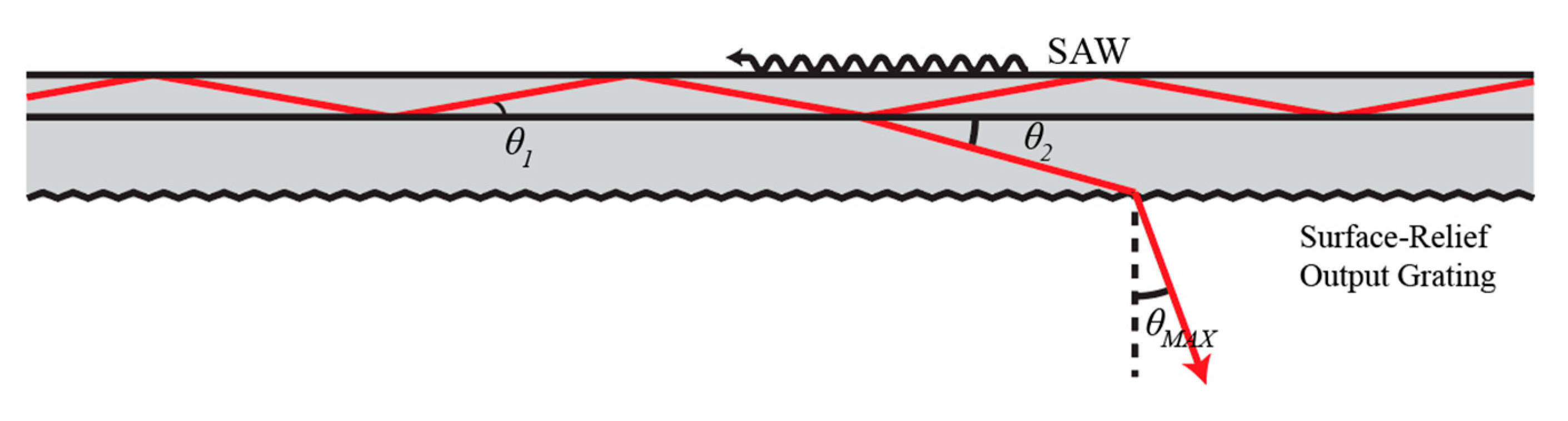
We provide a brief overview of the SAW–light interaction in
Figure 2. A single-mode waveguide carries polarized light at some initial angle,
, until the light encounters a surface acoustic wave traveling along the top of the waveguide. These waves will interact [
22], and the light will escape, or leak from, the waveguide at some angle
. With the correct setup, the leaky light will eventually encounter the back face of the substrate, where a surface-relief grating allows it to escape the substrate at exit angle or “maximum deflection angle”,
. The user’s eye would then be set behind this back plane at some set distance, and the total viewing area (or the total area that the user can look into and see an image) would be determined by the region over the device that allows for acousto-optic interaction.
2.2. Device Limitations
In order to properly analyze our device, we must consider the various limitations imposed by the system as it is currently envisioned. For example, the LiNbO
3 acousto-optic (AO) modulator is only capable of deflecting light (
in
Figure 2) by a few degrees (the current model achieves
of deflection for the fabrication parameters described in Laughlin et al.) [
10]. For the sake of this paper, we consider this angle to be 2°, although we will also allow for a −2° of deflection (by firing light down the waveguides in both directions), which gives a total of 4° of focus to our device (this is only a maximum deflection angle, and a smaller angle is used to draw points further in space). In addition, we primarily limit our analysis to a geometric consideration of the system, since that is what is required to show that the new geometry (using currently existing technology) will achieve a high field of view.
2.3. Viewzone and Field of View
For the purposes of this paper, we here consider the viewzone of the device to be the radial distance viewable by the user at any given point in image space. In contrast, the FOV will be the full angle of viewable area available to the user. This is illustrated in
Figure 3.
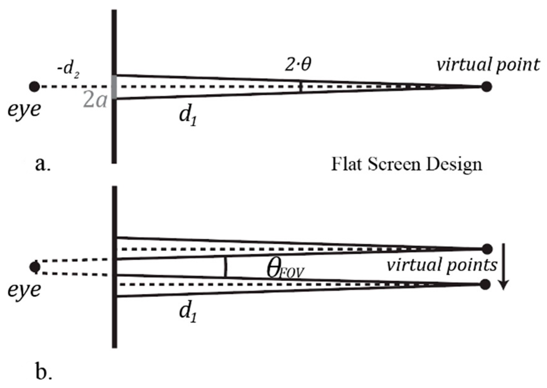
To determine the viewzone for a flat-screen device, we consider some point drawn by the active region of our device at some distance,
. This point is created by some converging phase front created out of an aperture, a; this can be defined by the angle underneath the virtual point, which we will call
(see
Figure 4a). As the point is drawn along the radial distance chosen, the aperture must likewise move along the available active region space (while some addition deflection is possible while maintaining a fixed aperture location, it will always be of a lower quality than the symmetrical, normal case, so here we ignore this).
When the virtual points are at their maximum distance, such that the eye can see both of them, the uppermost back-cast ray of one point and the lowest of the other will intersect at the eye, as seen in
Figure 4b. The angle subtended by the virtual points and the eye will be the FOV for this device.
It should be noted that, as the points are drawn closer to the eye, the maximum deflection angle will no longer be sufficient to converge to the chosen point; the closest drawable point that the display is capable of will be directly proportional to the aperture size chosen for the device, and the slope (as pictured above) will be . Therefore, this limitation can be overcome by choosing a smaller aperture size. For the aperture size we will choose in the future, however, this point will occur closer to the eye than the eye is capable of resolving, so this can be ignored. In contrast, as the virtual points are drawn further from the eye, the angle, , will necessarily shrink. This conforms to standard optical methods.
For a flat-screen device with
, a FOV of 4°, or
, is achievable. With an aperture size of approximately
17.5 mm, the device can draw points up to the limit of normal adult human vision, around 25 cm from the eye [
23].
3. Circular Screen
3.1. Purpose and Initial Concept
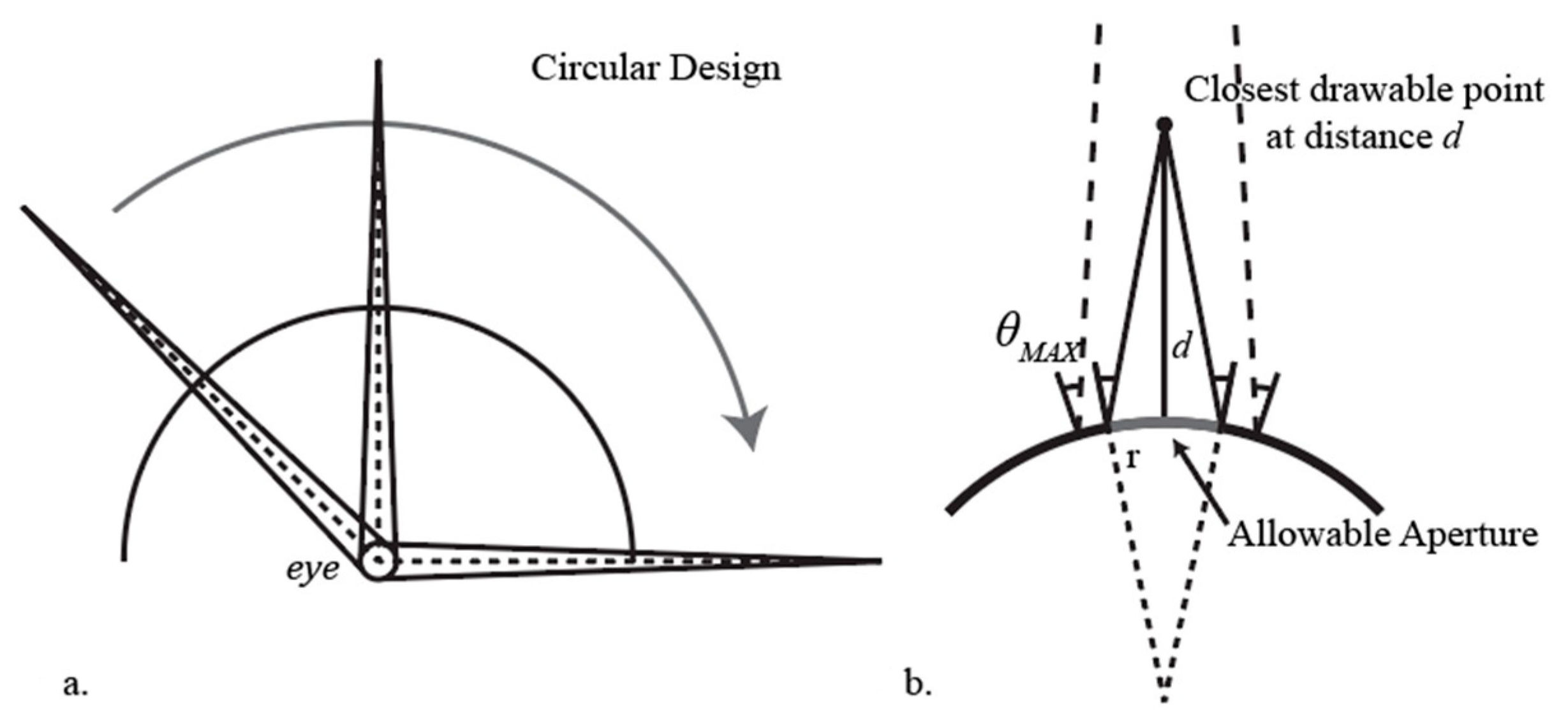
Our goal in creating a curved display is to increase the FOV while sacrificing the maximum aperture size allowed. Specifically, if the display has a radius of curvature (ROC) equal to its distance from the eye, then the FOV will automatically be 180° (or at least the angle subtended by the actual curved device). This behavior is demonstrated visually in
Figure 5a.
Both the flat and curved devices use the same underlying technology, and the flat case is already a proven method [
7,
8,
9,
10]. Curved or circular LiNbO
3 has been shown to propagate SAWs at similar levels to those achieved in flat cases [
24]. Furthermore, we show that, at the radius of curvatures and interaction lengths available, the curved device operates in a very similar fashion to the flat case.
The major consideration for this setup is the allowable aperture for drawing the virtual point. In contrast to the flat-screen case, where aperture and allowable draw distance has a linear relationship, the curved display adds a complication; that is, as the display curves, so does the
off the normal (see
Figure 5b). This means that, in order to achieve the maximum deflection possible, and therefore the closest point possible, the aperture size must be reduced.
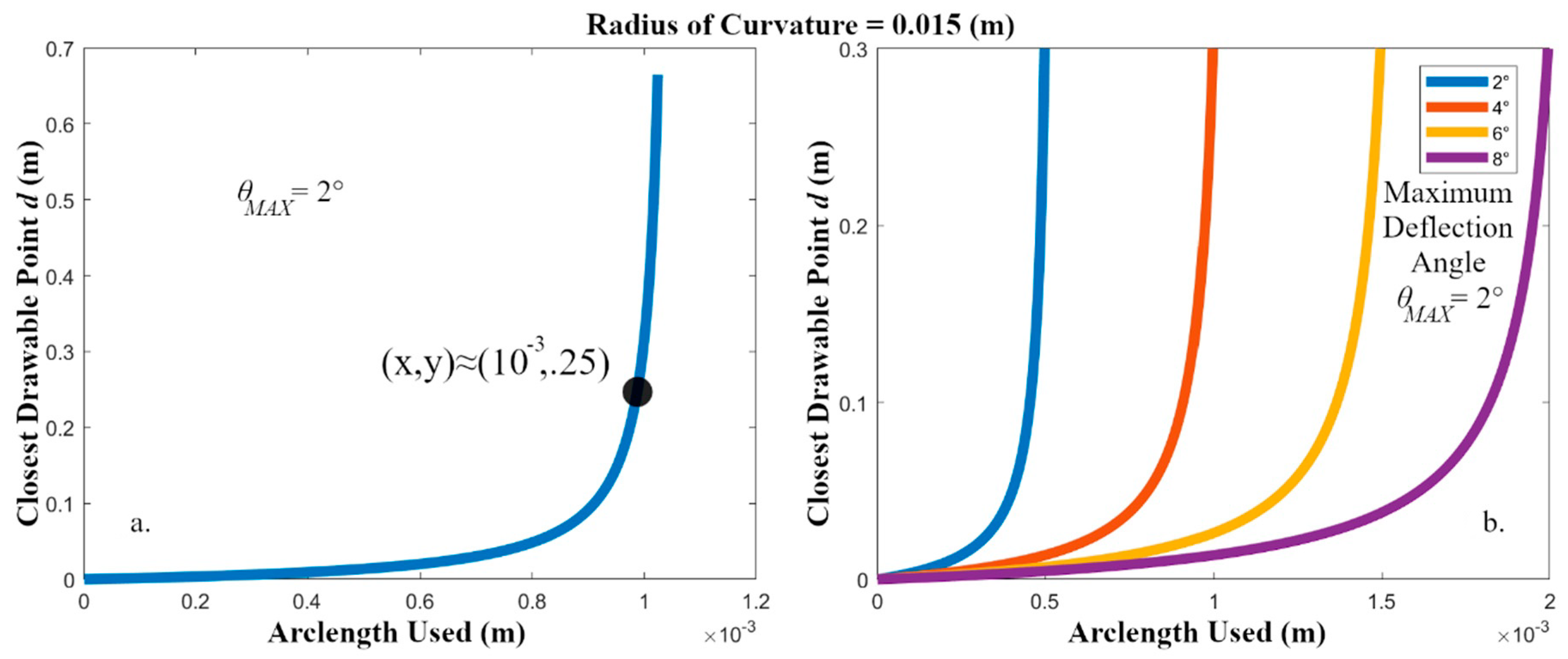
Figure 6a shows the relationship between aperture size and closest drawable point for a curved display of this type. Note that, as the arclength used increases (for a fixed ROC), the closest drawable points approaches infinity. The display can no longer converge to a point at any distance, since, with the distance along the curved surface increased, and therefore the angular offset between the endpoints increased, the
of deflection is no longer sufficient to converge to a point. Again, refer to
Figure 5b to understand this limitation.
In order to facilitate the design for this near-eye display, we choose to limit the allowable aperture to one size for all points drawn (for a given ROC). In practice, a variable aperture size would allow for greater control over points drawn further in space, but this would complicate the design outside the scope of a paper. Thus, we choose to limit the aperture to be whatever gives us a closest drawable point of 25 cm, which is the closest point the average human eye can focus to. For the device parameters shown in
Figure 6a, then, the aperture size chosen will be approximately 1 mm, which is much smaller than the allowable aperture for the flat-screen design.
As we design the flat-screen display, we endeavor to keep the aperture size as large as possible. The allowable aperture directly correlates to angular resolution and the point spread function of the focused beam; and although this falls outside the scope of this paper, it still informs our decisions regarding device design.
3.2. Theory
We now outline the principles and equations defining our system. The curved surface is placed in front of the eye, and the radius of curvature (ROC
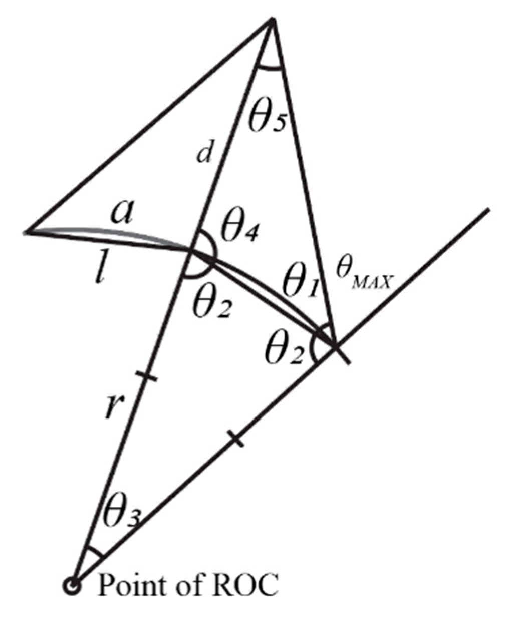
) is somewhere behind the eye (anywhere between infinity and directly at the center of the eye). The flat case is the same as the curved case with the ROC set at infinity. The angles and distances for the setup are defined in
Figure 7.
With a known radius of curvature and arclength, the closest drawable distance can be found. A similar method can be used to find the other two parameters. The equations, listed below, fall out directly from the Pythagorean Theorem, the Law of Cosines, and the Law of Sines. We use these equations to create
Figure 6,
Figure 8 and
Figure 9 by defining one parameter (ROC
or the closest drawable point, for example) and solving for the rest.
The variables in these equations are as follows: , as previously decided, is the closest drawable point, assuming we are using the maximum deflection allowed by the system. is the chord underneath the length , which runs along the region subtended by and represents half the allowable aperture of our system (given this closest drawable point and predetermined deflection angle). is equivalent to the FOV for the system, and is the radius of curvature. All other angles have no practical real-world meaning and serve only to find the final variables we seek.
4. Radius of Curvature vs. Field of View
We now briefly consider the case between the flat-screen and the circular design with the end of the ROC placed at the location of the eye (at distance ). Everything between these two edge cases can likewise be described in terms of a circle with an ROC somewhere behind the eye (keeping the distance between the display and the eye fixed). Indeed, even the flat-screen case is only an iteration of the curved case, where the ROC is infinite.
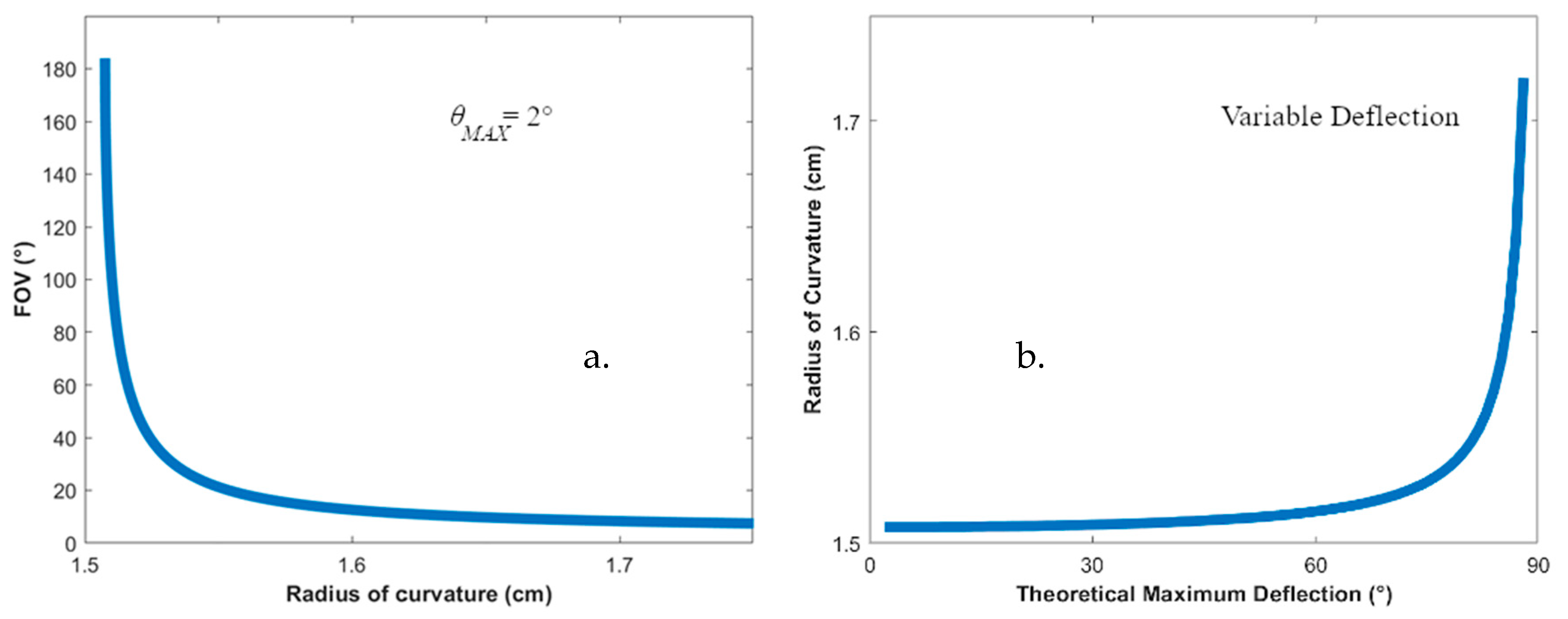
Figure 10 shows how the FOV is determined for a display with a given ROC. By constraining the aperture size and draw distance to some predetermined values, we can find the relationship of ROC and FOV. This relationship will run from a FOV of 4° (in the case of the flat screen) to 180° (when the radius of curvature = the distance from the display to the eye). The results for this scenario are shown in
Figure 8a. Note that the FOV in
Figure 8a is shown to extend slightly beyond 180°; this is because the simulation extends an extra
beyond the 180° arbitrary limit (on each side) imposed by the theoretical LiNbO
3 curved display. In reality, the FOV will be limited by the amount of useable hardware in the final instantiation of the product.
As we can see from
Figure 8a, choosing any radius other than one that falls on the eye gives a much smaller field of view. The slope of this falloff can be changed by choosing a larger aperture size, but that will necessitate placing the device much further from the eye in order to achieve a similar ability to converge, but because of the distance from the viewer, the virtual objects will have a proximity penalty. In addition, the improvement to the slope by increasing the aperture size is negligible when compared to the other compromises required to achieve it.
We also ask the question of whether we could move the ROC center past the eye by, one day, achieving a deflection angle greater than
.
Figure 8b considers this possibility. As we can see, even if this were the case, the device still fails to produce results much different from the
case until we reach the 90° case, which obviously would produce the full FOV regardless of curvature. In this way, we see that the device performance depends almost exclusively on the correct curvature and eye placement and has very little to do with angular deflection capability.
5. Design Graph for a Curved Near-Eye Display
In the circular case shown above (
Figure 6), the ROC was chosen to be 1.5 cm. We chose this distance because it is roughly similar to most eyewear currently on the market. As we can see from
Figure 8, choosing any radius other than one that falls on the eye gives a much smaller field of view; therefore, we opt to stick with the full curvature.
Another option available is to increase the ROC such that the display is further from the eye. The ROC, when compared to either the closest drawable point (from the eye) or the aperture size (holding the other fixed in either case), can be seen in
Figure 9.
These graphs indicate that increasing the ROC is beneficial, but only to a point which we now consider. Depending on the parameters chosen, this point will fluctuate, but two main observations can be made. The first is that the closest drawable point from the eye will improve as the display becomes flatter, but, after a certain point, the effects of flattening the display converge to the flat-screen case, and the linear effects of placing the display further from the eye, to compensate for the increased ROC increase. We generally want to avoid this linear region, not only because the drawable points sharply decrease, but also because the display ought to be reasonably close to the user in order to be considered a near-eye display.
The second item of note is that, as ROC increases, the allowable aperture will likewise increase, but this begins to slow as the curvature increases. Thus, for the example chosen in
Figure 9, anywhere past approximately ROC = 0.5 m, the aperture size will see diminished returns for the tradeoff of placing the display further from the user. Again, we want to keep the display close to the user, but because the space in which we do want to place the display shows such a large variation, we will try to place the display as far from the user as possible.
We have made the code used for this graph available for readers as Code 1 [
25].
6. Preferred Instantiation
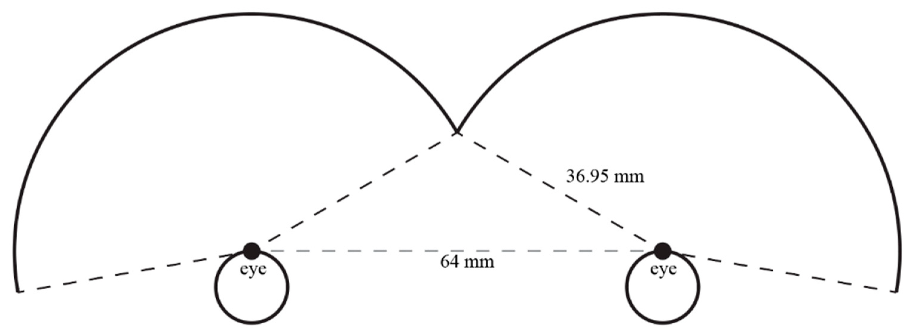
The ideal situation, given the previous information, would be to place the display as far from the user as possible. In practice, however, this display will be binocular, which means that if both eyepieces are to have an equal and full FOV, this will limit how far out the semicircular displays can be placed (if the eye is still to be at the center of the circle).
In addition, because the human eye has a maximum of 160° FOV, we can elect to crop parts of the circle to allow the display to gain further distance from the user. This will maximize our aperture size, and the closest drawable point will be 25 cm from the eye, with an aperture size of 2.2 mm. For an aperture of this size, the path curves a maximum of 65 nm, which is an order of magnitude less than the wavelength of the light, and multiple orders smaller than the SAW wavelength. Essentially, each interaction region can be treated as a miniature flat display. A sketch of this setup is shown in
Figure 11. The chosen parameters shown here conform to the design graph in
Figure 9.
The distance between the eyes is chosen to be 64 mm—the average interpupillary distance for a human adult male [
26].
7. Conclusions
We presented an analysis of curved-screen near-eye display technology using SAW-driven LiNbO3. This curved display has the potential to increase the viewzone and FOV for leaky-mode face-exit devices substantially. After considering the tradeoffs between FOV, ROC, aperture, and closest drawable point, we have put forth one possible instantiation, with a monocular FOV matching that of the human eye, and a binocular FOV surpassing 180°. We also offer a design graph for others that may be interested in pursuing this method of creating a high-FOV near-eye display.
Author Contributions
Conceptualization, J.C.L. and D.S. methodology, software, J.C.L.; validation, J.C.L. and D.S.; formal analysis, investigation, resources, data curation, writing—original draft preparation, writing—review and editing, visualization, J.C.L.; supervision, D.S.; project administration, D.S. All authors have read and agreed to the published version of the manuscript.
Funding
This research received no external funding.
Conflicts of Interest
The authors declare no conflict of interest.
References
- Li, G.; Lee, D.; Jeong, Y.; Cho, J. Holographic display for see-through augmented reality using mirror-lens holographic optical element. Opt. Lett. 2016, 41, 2486. [Google Scholar] [CrossRef] [PubMed]
- Chen, J.-S.; Chu, D. Improved layer-based method for rapid hologram generation and real-time interactive holographic display applications. Opt. Express 2015, 23, 18143. [Google Scholar] [CrossRef] [PubMed]
- Matteo, A.; Tsai, C.; Do, N. Collinear guided wave to leaky wave acoustooptic interactions in proton-exchanged LiNbO/sub 3/ waveguides. IEEE Trans. Ultrason. Ferroelectr. Freq. Control. 2000, 47, 16–28. [Google Scholar] [CrossRef] [PubMed]
- Liu, J.-P.; Hsieh, W.-Y.; Poon, T.-C.; Tsang, P. Complex Fresnel hologram display using a single SLM. Appl. Opt. 2011, 50, 128–135. [Google Scholar] [CrossRef] [PubMed] [Green Version]
- Notni, G.H.; Notni, G. Digital fringe projection in 3D shape measurement: An error analysis. In Proceedings of the Optical Measurement Systems for Industrial Inspection III, Munich, Germany, 23–26 June 2003; Volume 5144, pp. 372–381. [Google Scholar] [CrossRef]
- Robertson, B.; Zhang, Z.; Yang, H.; Redmond, M.M.; Collings, N.; Liu, J.; Lin, R.; Jeziorska-Chapman, A.M.; Moore, J.R.; Crossland, W.A.; et al. Reduction of crosstalk in a colourless multicasting LCOS-based wavelength selective switch by the application of wavefront encoding. In Proceedings of the SPIE OPTO, San Francisco, CA, USA, 21–26 January 2012; Volume 8284, p. 82840. [Google Scholar] [CrossRef]
- Smalley, D. Holovideo on a Stick: Integrated Optics for Holographic Video Displays. Ph.D Thesis, Massachusetts Institute of Technology, Cambridge, MA, USA, 2013. [Google Scholar]
- McClaughlin, S.; Leach, C.; Henrie, A.; Haymore, B.; Smalley, D.E.; Jolly, S.; Bove, V.M. Frequency Division of Color for Holovideo Displays using Anisotropic Leaky Mode Couplers. In Proceedings of the Digital Holography & 3-D Imaging Meeting, Shanghai, China, 24–28 May 2015; p. DM2A.2. [Google Scholar]
- Leach, C.; McLaughlin, S.; Henrie, A.; Haymore, B.; Smalley, D. Design and fabrication of a color multiplexing LiNbO3 device. In Proceedings of the 2015 IEEE 58th International Midwest Symposium on Circuits and Systems, Fort Collins, CO, USA, 2–5 August 2015; pp. 1–3. [Google Scholar]
- McLaughlin, S.; Henrie, A.; Gneiting, S.; Smalley, D.E. Backside emission leaky-mode modulators. Opt. Express 2017, 25, 20622–20627. [Google Scholar] [CrossRef] [PubMed]
- St-Hilaire, P. Scalable optical architecture for electronic holography. Opt. Eng. 1995, 34, 2900–2911. [Google Scholar] [CrossRef]
- Perkinson, J.C.; Moebius, M.G.; Brundage, E.J.; Teynor, W.A.; Byrnes, S.J.; Hsiao, J.C.; Sawyer, W.D.; Callahan, D.M.; Frank, I.W.; Leblanc, J.J.; et al. Surface-emitting electroholographic SAW modulator. Opt. Express 2020, 28, 1585–1594. [Google Scholar] [CrossRef] [PubMed]
- Cheng, D.; Wang, Y.; Xu, C.; Song, W.; Jin, G. Design of an ultra-thin near-eye display with geometrical waveguide and freeform optics. Opt. Express 2014, 22, 20705–20719. [Google Scholar] [CrossRef] [PubMed]
- Akşit, K.; Kautz, J.; Luebke, D. Slim near-eye display using pinhole aperture arrays. Appl. Opt. 2015, 54, 3422–3427. [Google Scholar] [CrossRef] [PubMed] [Green Version]
- Dunn, D.; Tippets, C.; Torell, K.; Kellnhofer, P.; Aksit, K.; Didyk, P.; Myszkowski, K.; Luebke, D.; Fuchs, H. Wide Field Of View Varifocal Near-Eye Display Using See-Through Deformable Membrane Mirrors. IEEE Trans. Vis. Comput. Graph. 2017, 23, 1322–1331. [Google Scholar] [CrossRef] [PubMed]
- Kun, A.; van der Meulen, H.; Janssen, C. Calling While Driving: An Initial Experiment with HoloLens. In Proceedings of the Ninth International Driving Symposium on Human Factors in Driver Assessment, Training and Vehicle Design, Manchester Village, VT, USA, 28 June 2017; pp. 200–206. [Google Scholar]
- Kruijff, E.; Swan, J.E.; Feiner, S. Perceptual issues in augmented reality revisited. In Proceedings of the 2010 IEEE International Symposium on Mixed and Augmented Reality, Seoul, Korea, 13–16 October 2010; pp. 3–12. [Google Scholar] [CrossRef]
- Benton, S.A.; McAllister, D.F.; Robbins, W.E. Alcove Holograms for Computer-Aided Design. In Proceedings of the OE LASE’87 and EO Imaging Symposium, Los Angeles, CA, USA, 16 June 1987; Volume 761, p. 53. [Google Scholar] [CrossRef]
- Ratcliff, J.; Supikov, A.; Alfaro, S.; Azuma, R. ThinVR: Heterogeneous microlens arrays for compact, 180 degree FOV VR near-eye displays. IEEE Trans. Vis. Comput. Graph. 2020, 26, 1981–1990. [Google Scholar] [CrossRef] [PubMed]
- Hedili, M.K.; Freeman, M.O.; Urey, H. Microlens array-based high-gain screen design for direct projection head-up displays. Appl. Opt. 2013, 52, 1351–1357. [Google Scholar] [CrossRef] [PubMed] [Green Version]
- Orlosky, J.; Wu, Q.; Kiyokawa, K.; Takemura, H.; Nitschke, C. Fisheye vision. In Proceedings of the 2nd ACM Symposium on Spatial User Interaction, Honolulu, HI, USA, 4 October 2014; Association for Computing Machinery: New York, NY, USA, 2014; pp. 54–61. [Google Scholar]
- Yamanouchi, K.; Higuchi, K.; Shibayama, K. High Efficient TE-TM Mode Converter by Interaction between Acoustic Surface Waves and Laser Beams on LiNbO3. In Proceedings of the 1977 Ultrasonics Symposium, Phoenix, AZ, USA, 26–28 October 1977; pp. 447–450. [Google Scholar] [CrossRef]
- Mouroulis, P.; Macdonald, J. Geometrical Optics and Optical Design; Oxford University Press: Oxford, UK, 1997. [Google Scholar]
- Akao, S.; Nakaso, N.; Ohgi, T.; Yamanaka, K. Observation of the Roundtrips of Surface Acoustic Waves on a Single Crystal LiNbO3Ball. Jpn. J. Appl. Phys. 2004, 43, 3067–3070. [Google Scholar] [CrossRef]
- Leach, J.C. Radius of Curvature vs. Arc Length, Figshare. Available online: https://figshare.com/articles/software/arclength_vs_closest_distance_m/12965093 (accessed on 16 September 2020).
- Dodgson, N. Variation and extrema of human interpupillary distance. Electr. Imag. 2004, 5291, 36–46. [Google Scholar] [CrossRef]
Figure 1.
An example of an edge-exit vs. face-exit device.
Figure 1.
An example of an edge-exit vs. face-exit device.
Figure 2.
The original design for a face-exiting flat-screen near-eye display.
Figure 2.
The original design for a face-exiting flat-screen near-eye display.
Figure 3.
(a) Viewzone is defined by a viewable radial length at some distance, d; field of view (FOV) is the angle of information accessible by the eye. (b) The goal of this paper is to improve the FOV by curving the device’s active region. This will allow the user to see a greater viewzone.
Figure 3.
(a) Viewzone is defined by a viewable radial length at some distance, d; field of view (FOV) is the angle of information accessible by the eye. (b) The goal of this paper is to improve the FOV by curving the device’s active region. This will allow the user to see a greater viewzone.
Figure 4.
(a) The virtual point is limited by the aperture and distance drawn. The angle allowed by these parameters depends on the maximum deflection angle of the device. (b) The maximum length perceived by the eye at any distance is found by dragging the aperture along the active region until the back-traced rays fall just barely on the eye. The angle from the eye to the virtual points defines the FOV.
Figure 5.
(a) For a curved display with the eye placed at the radius of the curvature, as the virtual point is radially drawn at a fixed distance from the eye, the normal to the device will always fall on the eye, and the point is guaranteed to be seen by the eye. Thus, the FOV of the device is 180°. (b) The closest drawable point at distance, , is determined by the radius of curvature. As the curvature increases, the angle between the normals will offset the deflection on each side. This limits the closest point possible faster than in the flat case.
Figure 6.
(
a) As the arclength (2
in
Figure 7) increases, the ability of the device to focus on a point near the eye is reduced. This eventually reaches a point where, due to the curvature of the device, the
afforded by the device is insufficient to draw any point. (
b) Here, we consider different deflection angles,
. As expected, increasing the deflection angle allows us to use a larger arclength.
Figure 7.
The various angles are labeled as “_”. Half of the aperture is labeled “a”, and the secant under the arc is “l”. The maximum deflection from the normal is required at either end of the shaped beam and is defined, for this paper, as . The figure is not drawn to scale, in order to improve viewability.
Figure 8.
(a) In this scenario, we set maximum deflection angle at , and we place a curved display (arbitrarily) 5 cm in front of the eye and hold that fixed position. As the radius of curvature of the display increases past the eye, the FOV rapidly decreases until it converges to the 4° flat-screen case. (b) Here, we hold the FOV = 180° and the distance of the eye from the device to 1.5 cm. If we allow for the possibility of an increased deflection angle in the future, we see that, even at high deflection angles, the possibility of moving the eye from the ROC center and maintaining our high FOV is minimal.
Figure 9.
(
a) The largest aperture allowed for the device is displayed here with respect to the radius of curvature (when
). The closest point the display can focus to is held at 25 cm (from the eye). (
b) The closest point
the display can focus to is displayed here with respect to the radius of curvature (when
). The aperture size (created by the active region of the device) is held at 2.2 mm. (
c)
Figure 6a and
Figure 10a are 2D cross-sections of this plot; they are shown as dashed lines. The intersection point is chosen for the preferred instantiation in
Section 6.
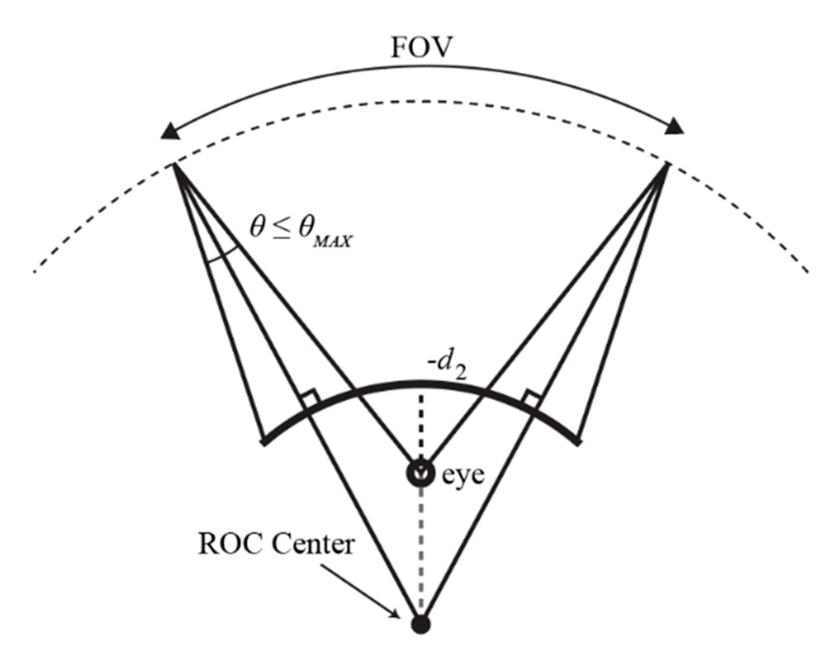
Figure 10.
A display with a radius of curvature (ROC) placed behind the eye will have some angular view that the eye can perceive. The point (on either side of the eye) at which this no longer is true is where the furthest ray towards the eye no longer falls on the eye.
Figure 10.
A display with a radius of curvature (ROC) placed behind the eye will have some angular view that the eye can perceive. The point (on either side of the eye) at which this no longer is true is where the furthest ray towards the eye no longer falls on the eye.
Figure 11.
A binocular near-eye display with a maximum radius of curvature, given the average distance between human adult male eyes.
Figure 11.
A binocular near-eye display with a maximum radius of curvature, given the average distance between human adult male eyes.
© 2020 by the authors. Licensee MDPI, Basel, Switzerland. This article is an open access article distributed under the terms and conditions of the Creative Commons Attribution (CC BY) license (http://creativecommons.org/licenses/by/4.0/).

