Article

A Novel Comprehensive Method for Modeling and Analysis of Mesh Stiffness of Helical Gear

1
State Key Laboratory of Mechanical Transmissions, Chongqing University, Chongqing 400044, China
2
State Key Laboratory of Mining Equipment and Intelligent Manufacturing, Taiyuan Heavy Machinery Group Co., Ltd., Taiyuan 030024, China
3
Institute of Beautiful China Development, Sanming University, Sanming 365000, China
*
Author to whom correspondence should be addressed.
Appl. Sci. 2020, 10(19), 6695; https://doi.org/10.3390/app10196695
Submission received: 5 September 2020 / Revised: 16 September 2020 / Accepted: 22 September 2020 / Published: 24 September 2020
(This article belongs to the Section Mechanical Engineering)

Abstract

:
The mesh stiffness of gear pairs used in aerospace applications, such as geared turbofan, has a vital influence on vibration and noise. To compensate for the deficiencies of the conventional method that does not consider slice coupling and structure coupling simultaneously, a comprehensive mathematical model for computing the mesh stiffness of helical gears is established. In this novel model, the effect of structure coupling and slice coupling between neighboring sliced gears are considered. The effect of the axial component of meshing force is also taken into account simultaneously. The results obtained by the comprehensive model are consistent with the finite element method and it proves that the novel mathematical model is sound. The influences of the helical angle and addendum modification coefficient on mesh stiffness are studied. The results show that the mesh stiffness of helical gears would be decreased in multiteeth regions caused by structure coupling. With or without consideration of the axial component, the relative mean values of mesh stiffness become larger with an increasing helical angle. The fluctuation value of mesh stiffness decreases when a positive addendum modification coefficient is adopted. The addendum modification also changes the phase of mesh stiffness. This study is helpful for a vibration analysis of gear transmission systems.

1. Introduction

Gear transmission is widely used in aerospace [1,2], vehicles [3], wind turbines [4,5], etc. The mesh stiffness of gear pairs is an important excitation when a dynamic analysis is executed, and its accuracy has a significant effect on the results of the dynamic response [6,7]. Many researchers have studied the methods for computing mesh stiffness. The methods can be summed up as the experimental method, finite element method, and analytical method.
Generally, the experimental method is considered as conforming to reality. Munro obtained the mesh stiffness by the experimental method over a range of tooth loads [8]. Raghuwanshi acquired the stress factor and calculated the mesh stiffness [9,10]. Karpat designed a special test rig to measure the stiffness of an involute spur gear [11]. However, special facilities with a high cost are required to conduct experiments. Therefore, the finite element method is adopted by many researchers. Based on a Siemens NX and ANSYS Workbench, Zhan developed a technique to obtain the mesh stiffness [12]. Li obtained the mesh stiffness of a cylindrical gear by considering the fillet-foundation as a rigid body or flexible body [13]. By using the finite element method, Wang studied the torsional stiffness [14]. Wei analyzed the mesh stiffness with profile modification by the finite element method [15]. Nevertheless, many hours are required when the finite element method is used because this method deeply depends on the computer configuration.
The analytical method has also been adopted to obtain the mesh stiffness with the goal of reducing the cost of experiments and the computing time required by the finite element method. Yang first obtained the mesh stiffness with the assumption that the total potential energy can be sorted into three parts: bending, radial compressive and Hertzian contact energy [16]. On this basis, Tian added the shear energy into the model [17,18]. Additionally, Sainsot fitted a formula to calculate the deformation of the fillet-foundation [19]. Chen established a general combined model to obtain the mesh stiffness [20]. Sanisot’s formula only applied the single-tooth engagement region. Ma proposed a correction factor to eliminate this deficiency [21]. Xie derived the formula to calculate the stiffness of the fillet-foundation when two tooth pairs of a spur gear are engaged simultaneously [22]. Wang first considered the influence of axial force on the mesh stiffness of helical gears [23]. Rezaei extracted the mesh stiffness of a helical gear by using the slice method and then extended the equation to a helical planetary gear train [24]. Seager established the relationship between the loading and deflection, and then analyzed the static behavior of helical gears [25]. Yu studied the influence of addendum modification on the mesh stiffness of spur gears [26]. Ma et al. carried out a study on the mesh stiffness of gears with microcracks [27]. In the above literatures, the helical gear is considered as many independent spur gears, and the effect of the relationship between neighboring sliced gears and the influence of the axial mesh force on the comprehensive mesh stiffness have not been considered simultaneously. Obviously, the literature is incomplete.
In order to reduce the cost of the experimental method and the calculating time of finite element method, and make up for the shortcomings of the traditional analytical method, this paper focuses on establishing a comprehensive analytical model for evaluating the mesh stiffness of the helical gear. Firstly, the helical gear is divided into independent sliced gears along the direction of gear width by using slice theory. Considering the effect of the relationship between neighboring sliced gears, the comprehensive mesh stiffness of the helical gear can be acquired. Secondly, with regard to each sliced gear, the bending, shear, and torsional stiffness of the tooth with axial force and the bending, shear, and radial compression stiffness of the tooth with transverse force are presented, and the bending stiffness of the fillet-foundation with axial force and transverse force are presented. For each sliced gear, the effect of structure coupling is considered. Thirdly, the comprehensive analytical model is validated compared with the finite element method via two sets of gear parameters. Finally, the influences of the helical angle and addendum modification coefficient on mesh stiffness are investigated.

2. The Analytical Model of Mesh Stiffness of Helical Gear

With the existence of a helical angle, slice theory can be used to compute the mesh stiffness of a helical gear, and the axial effect should also be considered. Thus, the axial and transverse stiffness are calculated, respectively. The stiffness model considering the effect of the relationship between neighboring sliced gears is established.

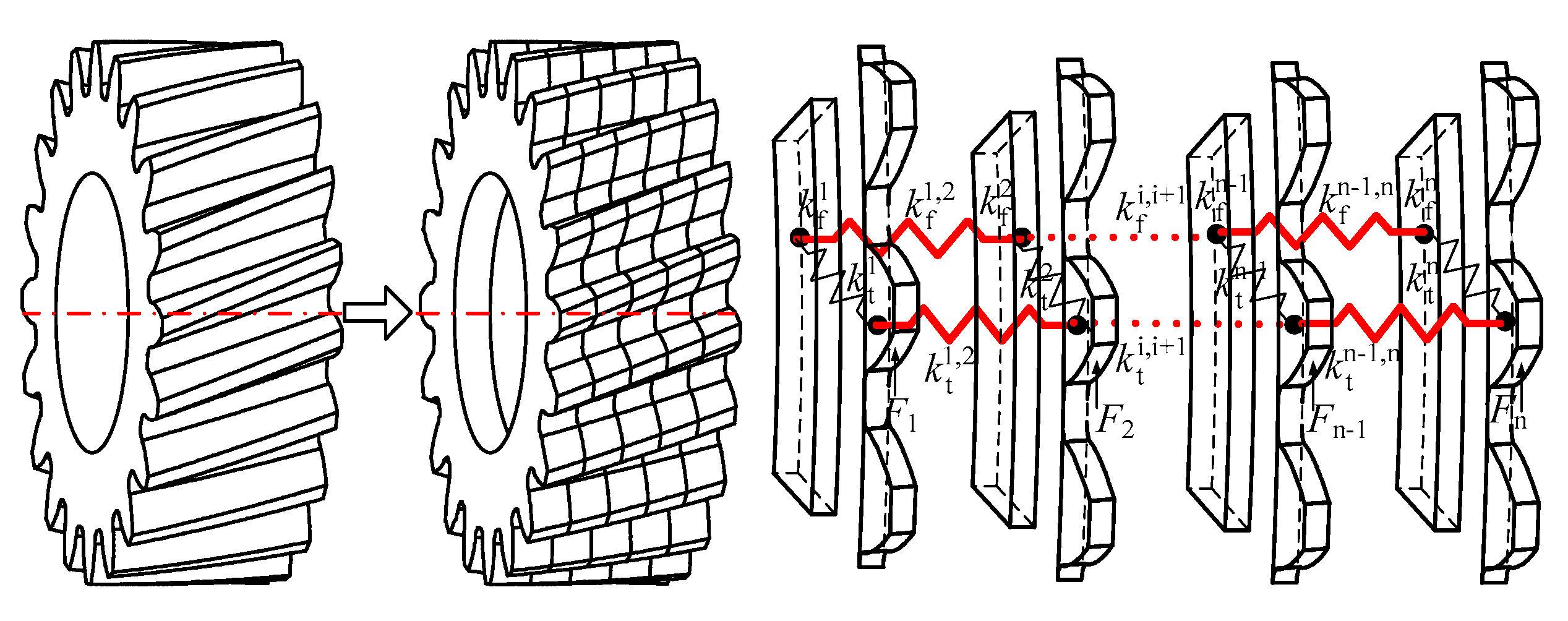
2.1. The Relationship between Neighboring Sliced Gears

According to slice theory, one helical gear can be divided into n independent sliced gears along the width direction. The sliced gears are connected by slice coupling stiffness. k t i , i + 1 and k f i , i + 1 denote the coupling stiffness between teeth and the coupling stiffness between the fillet-foundation, as shown in Figure 1.
Based on the relationship between neighboring sliced gears, for each sliced gear, the following equation can be deduced:
{ k t 1 ( δ t , 1 δ f , 1 ) + k t 1 , 2 ( η 1 δ t , 1 η 2 δ t , 2 ) = F 1 k f 1 δ f , 1 + k t 1 ( δ f , 1 δ t , 1 ) + k f 1 , 2 ( δ f , 1 δ f , 2 ) = 0 k t 2 ( δ t , 2 δ f , 2 ) + k t 1 , 2 ( η 2 δ t , 2 η 1 δ t , 1 ) + k t 2 , 3 ( η 2 δ t , 2 η 3 δ t , 3 ) = F 2 k f 2 δ f , 2 + k t 2 ( δ f , 2 δ t , 2 ) + k f 1 , 2 ( δ f , 2 δ f , 1 ) + k f 2 , 3 ( δ f , 2 δ f , 3 ) = 0 k t n ( δ t , n δ f , n ) + k t n 1 , n ( η n δ t , n η n 1 δ t , n 1 ) = F n k f n δ f , n + k t n ( δ f , n δ t , n ) + k f n 1 , n ( δ f , n δ f , n 1 ) = 0
where δf,i, δt,i represent the deformation of the fillet-foundation and tooth, respectively. k f i , k t i represent the stiffness of the fillet-foundation and tooth, respectively. Fi represents the external force. ηi donates the value of the deflection of the loading point divided by the deflection of the tooth center. It should be noted that the above symbols refer only to a sliced gear.
The above equations can be rewritten as follows:
[ k t 1 + η 1 k t 1 , 2 k t 1 η 2 k t 1 , 2 0 0 0 k t 1 k f 1 + k t 1 + k f 1 , 2 0 k f 1 , 2 0 0 η 1 k t 1 , 2 0 k t 2 + η 2 k t 1 , 2 + η 2 k t 2 , 3 k t 2 0 0 0 k f 1 , 2 k t 2 k f 2 + k t 2 + k f 1 , 2 + k f 2 , 3 0 0 0 0 0 0 k t n + η n k t n 1 , n k t n 0 0 0 0 k t n k f n + k t n + k f n 1 , n ] [ δ t , 1 δ f , 1 δ t , 2 δ f , 2 δ t , n δ f , n ] = [ F 1 0 F 2 0 F n 0 ]
That is,
K p δ p = F p
where
K p = [ k t 1 + η 1 k t 1 , 2 k t 1 η 2 k t 1 , 2 0 0 0 k t 1 k f 1 + k t 1 + k f 1 , 2 0 k f 1 , 2 0 0 η 1 k t 1 , 2 0 k t 2 + η 2 k t 1 , 2 + η 2 k t 2 , 3 k t 2 0 0 0 k f 1 , 2 k t 2 k f 2 + k t 2 + k f 1 , 2 + k f 2 , 3 0 0 0 0 0 0 k t n + η n k t n 1 , n k t n 0 0 0 0 k t n k f n + k t n + k f n 1 , n ]
δ p = [ δ t , 1 ,       δ f , 1 ,       δ t , 2 ,       δ f , 2 ,       ,       δ t , n ,       δ f , n ] T
F p = [ F 1 ,         0 ,         F 1 ,         0 ,                 F n ,         0 ] T
Obviously, Kp is a function of k t 1 , k t 2 , …, k t n , k f 1 , k f 2 , …, k f n , k t 1 , 2 , k t 2 , 3 , …, k t n 1 , n and k f 1 , 2 , k f 2 , 3 , …, k f n 1 , n .
Thus, the displacement of the sliced driving gear considering the slice coupling stiffness can be deduced:
δ p = K p 1 F p
Similarly, the displacement of the sliced driven gear also can be obtained:
δ w = K w 1 F w
The total deformation of each sliced gear pair considering the slice coupling stiffness can be obtained as follows:
δ = δ p + δ w + δ h = K p 1 F + K w 1 F + K h 1 F = [ K p 1 + K w 1 + K h 1 ] F = A F
As a result, the mesh stiffness of each sliced gear pair can be expressed as follows:
k i = ( j = 1 n A 2 i 1 , 2 j 1 + j = 1 n A 2 i , 2 j 1 ) 1
The total mesh stiffness of a helical gear is the sum of each sliced gear pair considering slice coupling. Therefore, only k t 1 , k t 2 , …, k t n , k f 1 , k f 2 , …, k f n , k t 1 , 2 , k t 2 , 3 , …, k t n 1 , n , and k f 1 , 2 , k f 2 , 3 , …, k f n 1 , n are needed to compute mesh stiffness ki.
The slice coupling stiffness of a tooth k t i 1 , i (i = 1, 2, …, n − 1) consists of torsional stiffness k tt i 1 , i and shear stiffness k ts i 1 , i .
k tt i 1 , i = G I p r 2 b , k ts i 1 , i = G A 1 α s b
where G donates shear modulus, Ip donates cross-section polar moments of inertia, r donates the radius of the point where the load is applied, b donates the sliced gear width, A1 donates the area of the tooth section parallel to the transverse face, and αs donates the shear factor.
The slice coupling stiffness of the fillet-foundation k f i 1 , i (i = 1, 2, …, n − 1) consists of torsional stiffness k ft i 1 , i and shear stiffness k fs i 1 , i . These stiffness values can be obtained by the similarity formula.

2.2. The Stiffness of Each Sliced Gear

Due to the existence of the helix angle, the helical gear has deformation not only along transverse direction but also along axial direction under the action of normal force on the tooth surface. Therefore, it is not accurate to just consider the compliance along the transverse direction when calculating the mesh stiffness. The compliance along the axial direction must be taken into account. For teeth and fillet-foundation, the comprehensive compliance is the sum of transverse compliance and axial compliance.
The total mesh force Fi can be decomposed into axial force Fa and transverse force Ft, as shown in Figure 2. The axial stiffness ka is produced by axial mesh force, and the transverse stiffness kt is produced by transverse mesh force. The relationship among the total mesh force, axial mesh force, and transverse mesh force can be written as
F t = F i · cos β b                     F a = F i · sin β b
where βb denotes the helical angle on the base circle.

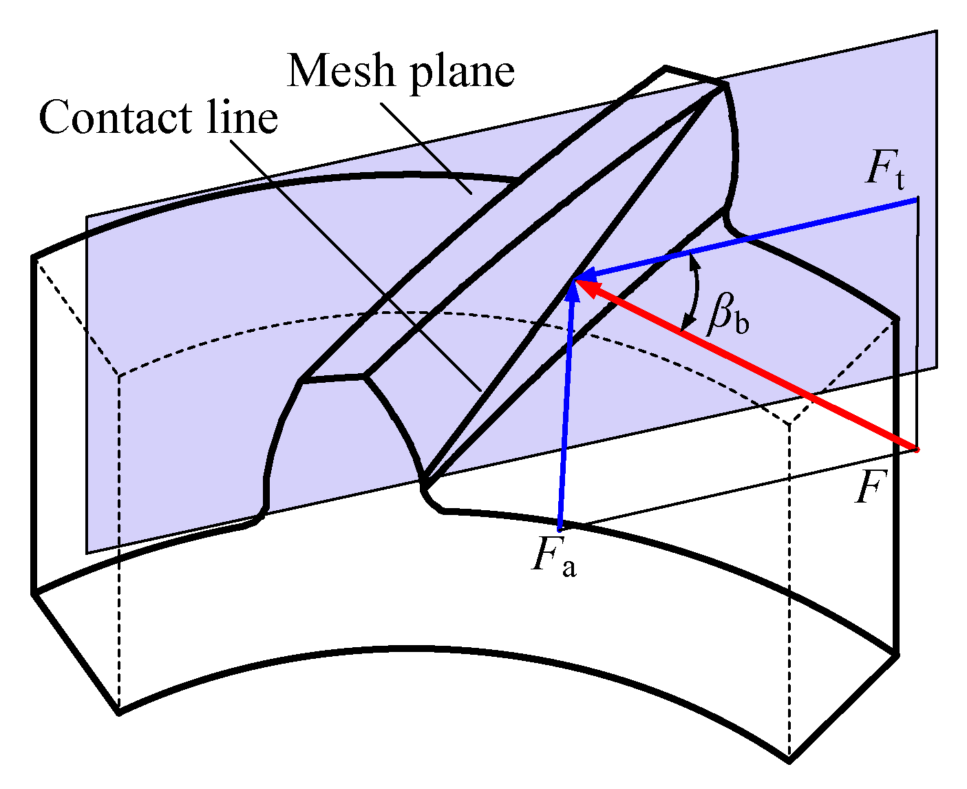
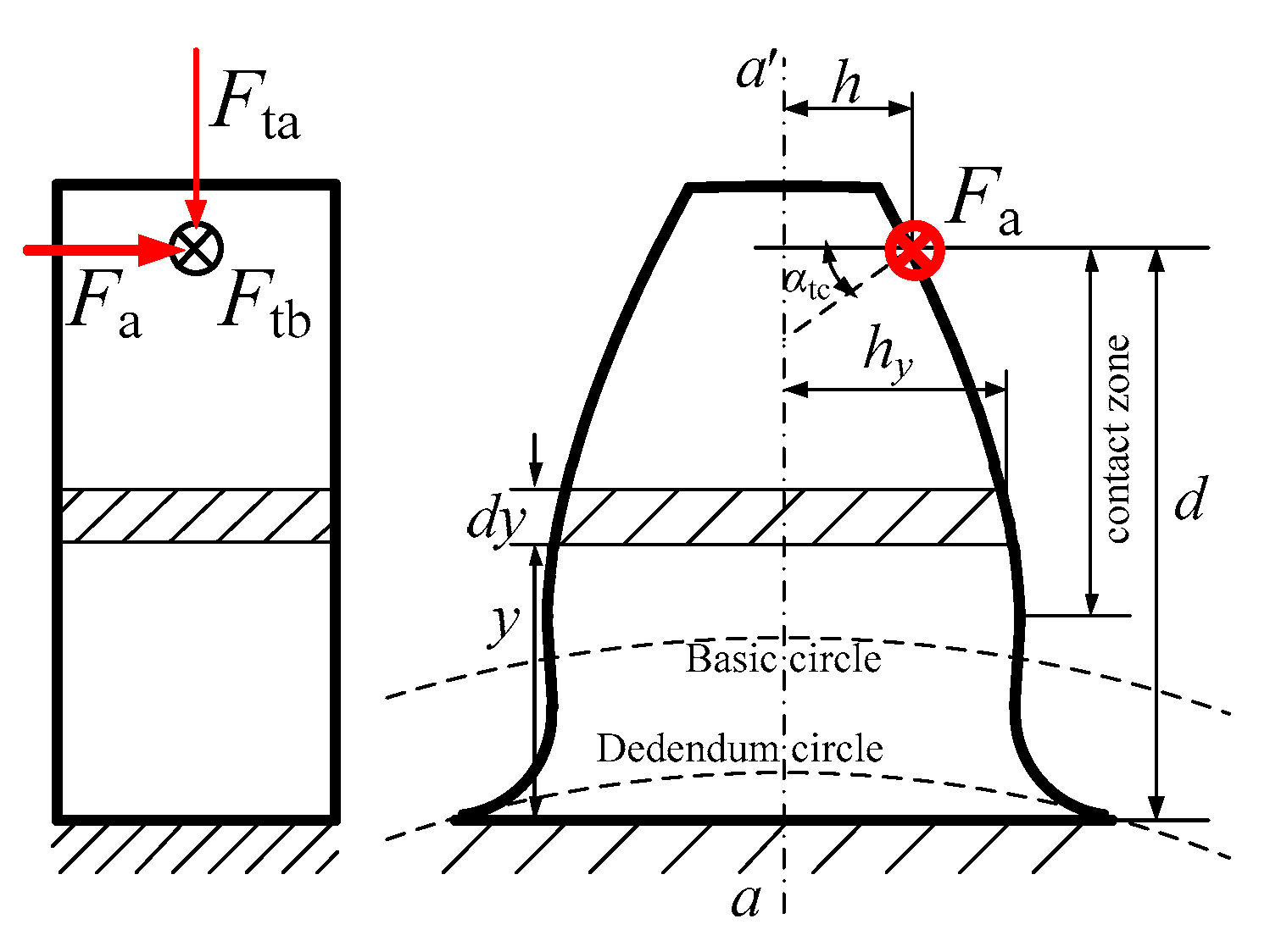
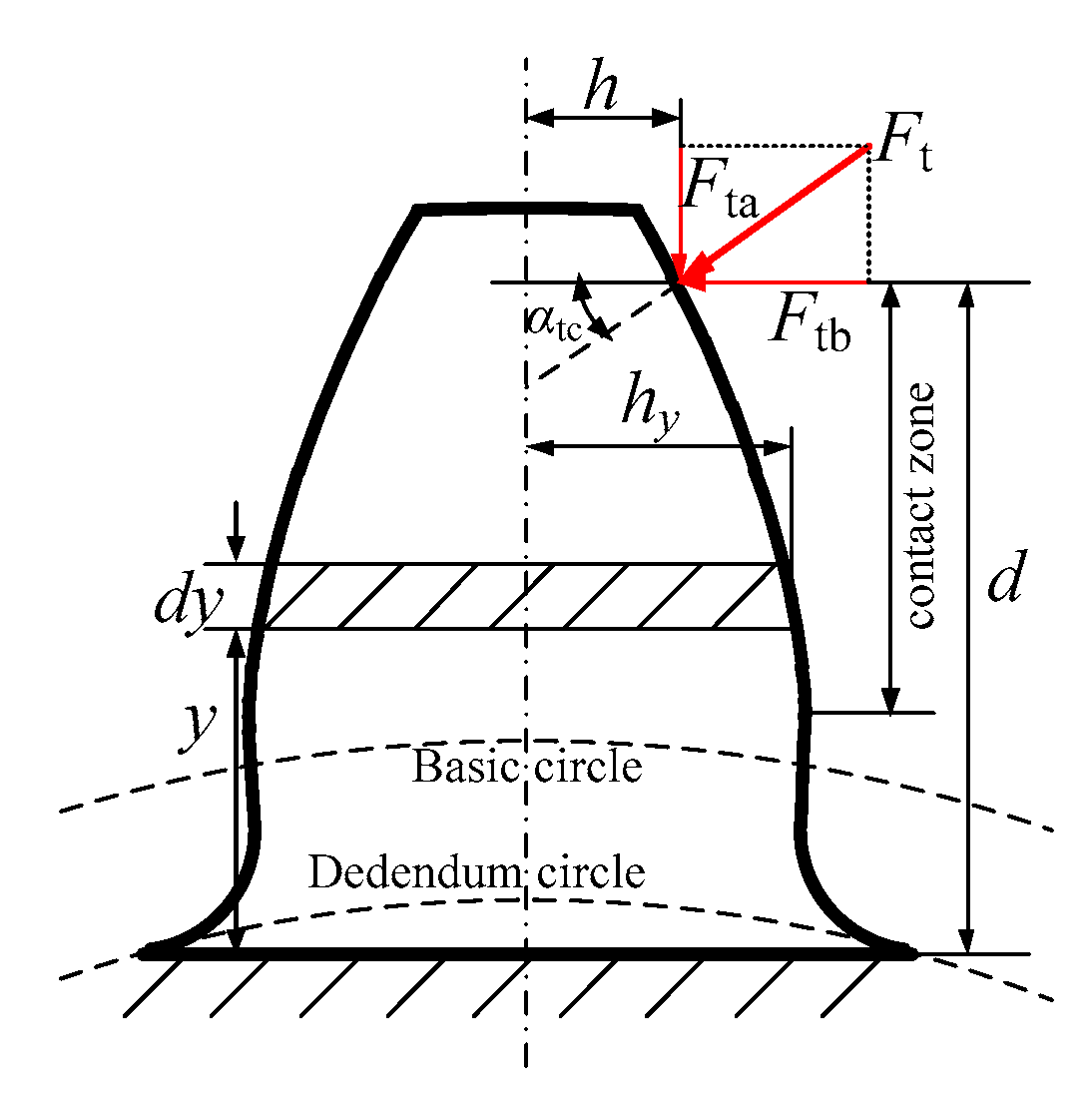
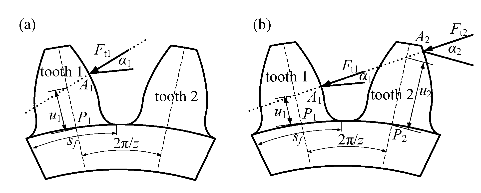
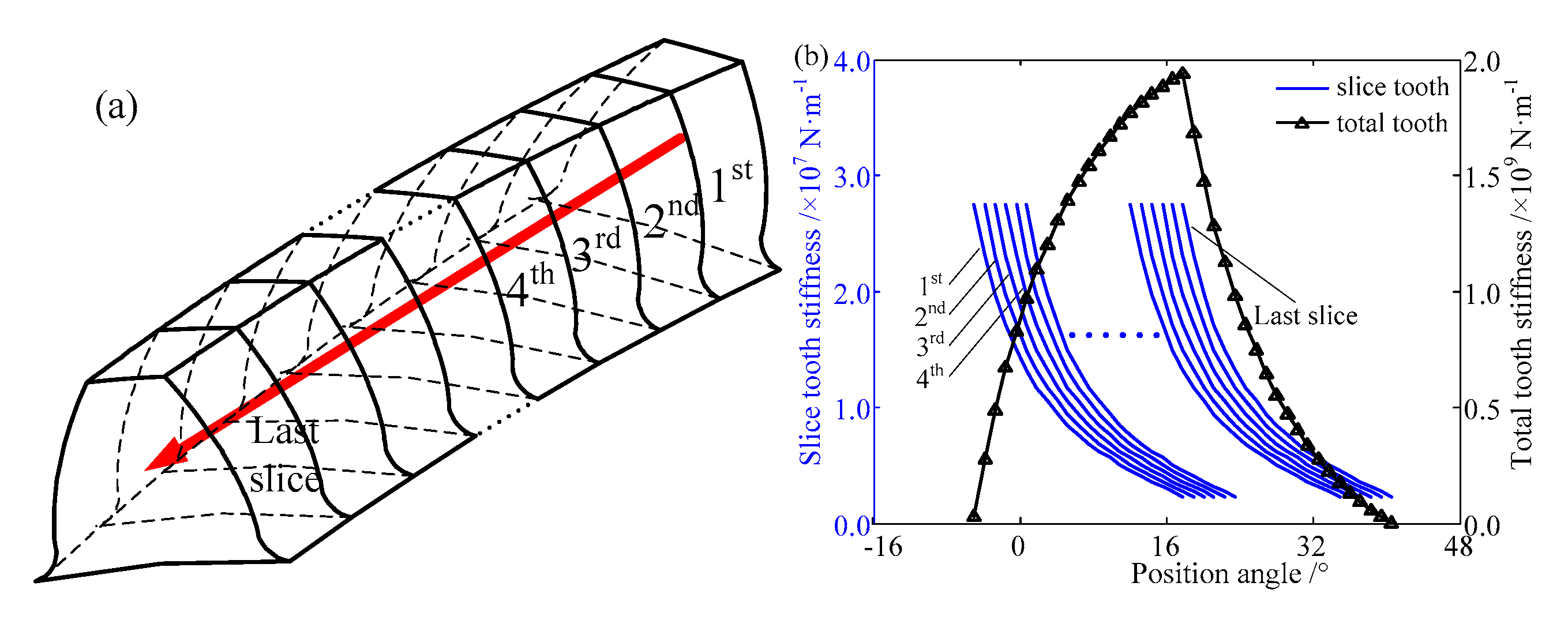
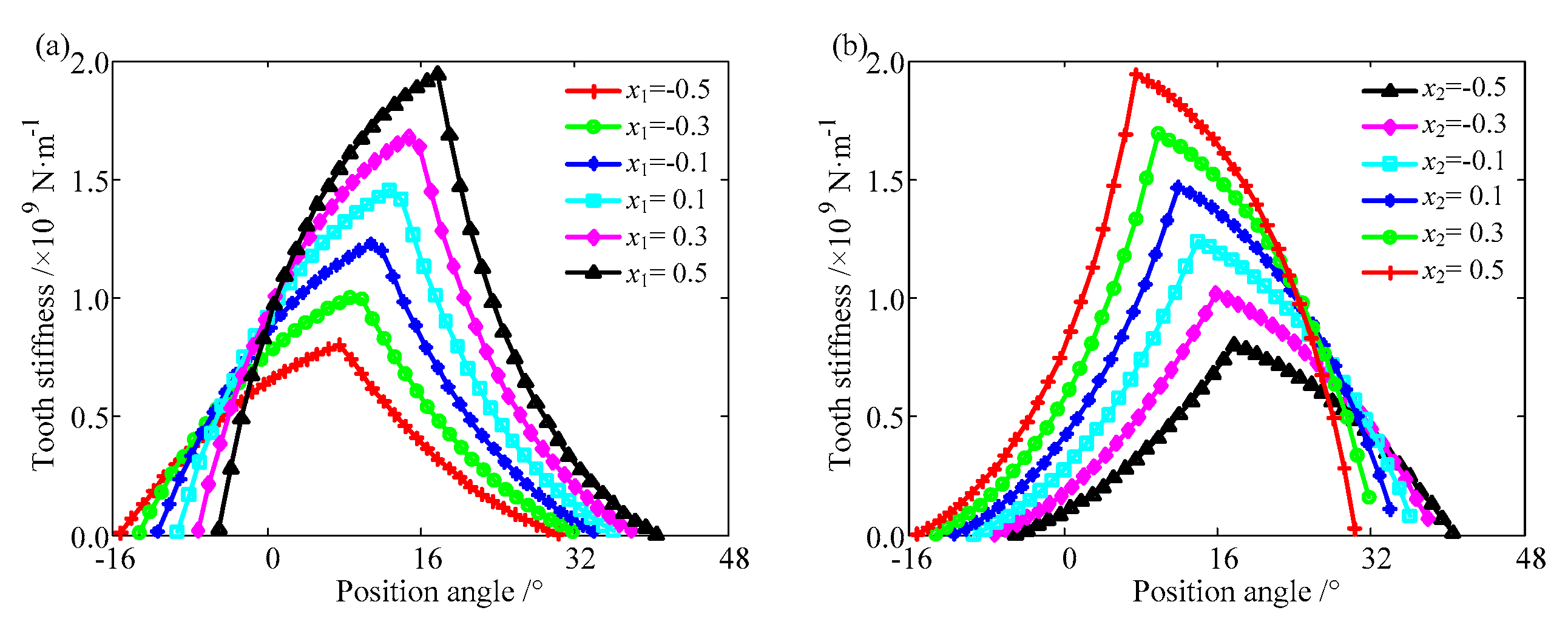
2.2.1. Tooth Stiffness

There is deformation of the tooth with the effect of axial force. The tooth can be considered as a cantilever beam whose root is fixed, as shown in Figure 3.
According to beam theory in elastic mechanics, the bending, shear, and torsional energy with the axial mesh force can be calculated by
U a t b = 0 d M a t b 2 2 E I a t x d y , U a t s = 0 d 1.2 F a 2 2 G A 2 d y , U a t t = 0 d M a t t 2 2 G I a t p d y
According to Hooke’s law, the potential energy can be written as follows:
U a t b = F i 2 2 k a t b , U a t s = F i 2 2 k a t s , U a t t = F i 2 2 k a t t
As a result, the bending, shear, and torsional stiffness of the tooth with axial mesh force can be obtained as
1 k atb = 0 d sin 2 β b · ( d y ) 2 E I a t x d y , 1 k ats = 0 d 1.2 · sin 2 β b G A 2 d y , 1 k att = 0 d sin 2 β b · h 2 G I atp d y
where G and E represent shear and Young’s moduli, respectively. Iatx denotes the cross-sectional moment of inertia to the neutral axis. Iatp denotes the cross-sectional polar moment of inertia.
Moreover, there also exists deformation of the tooth with the effect of transverse force. The tooth also can be considered as a cantilever beam whose root is fixed. The sketch of the tooth with the transverse force is shown in Figure 4.
According to beam theory in elastic mechanics, the bending, shear, and radial compression energy with the transverse mesh force can be calculated as follows:
U t t b = 0 d M t t b 2 2 E I t t x d y , U t t s = 0 d 1.2 F t b 2 2 G A 2 d y , U t t r = 0 d F t a 2 2 E A 2 d y
According to Hooke’s law, the potential energy can be written as follows:
U t t b = F 2 2 k t t b , U t t s = F 2 2 k t t s , U t t r = F 2 2 k t t r
As a result, the bending, shear, and radial compression stiffness of the tooth with transverse mesh force can be obtained as
1 k ttb = 0 d cos 2 β b · [ cos α tc · ( d y ) h · sin α tc ] 2 E I t t x d y 1 k tts = 0 d 1.2 · cos 2 β b · cos 2 α tc G A 2 d y 1 k ttr = 0 d cos 2 β b · sin 2 α tc E A 2 d y
where Ittx denotes the cross-sectional moment of inertia to the neutral axis. A2 denotes the area of a tooth section perpendicular to the transverse face.
The total energy stored in a tooth with total mesh force can be written as
U t = U a t b + U a t s + U a t t + U t t b + U t t s + U t t r
As a result, the comprehensive tooth stiffness of a sliced gear can be computed as
1 k t = 1 k a t b + 1 k a t s + 1 k a t t + 1 k t t b + 1 k t t s + 1 k t t r

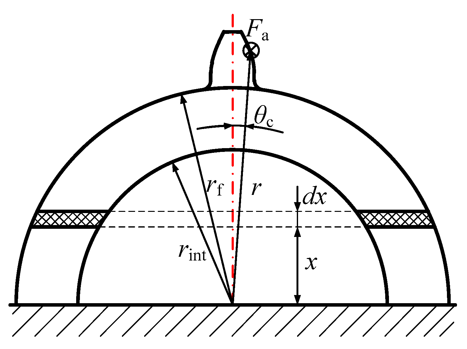
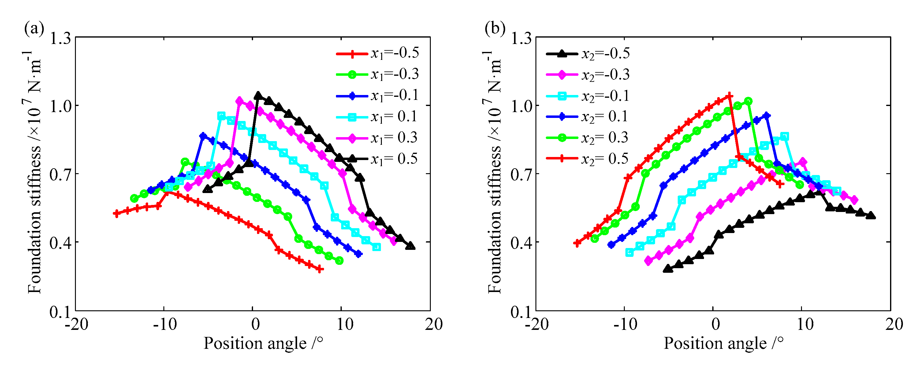
2.2.2. Fillet-Foundation Stiffness

As in the tooth, the fillet-foundation undergoes deformation with the axial force. The fillet-foundation can also be considered as a cantilever beam, as shown in Figure 5. The bending moment of the fillet-foundation with the axial force can be calculated as
M af = F a · ( r · cos θ c x )
The bending energy stored in the fillet-foundation with the axial mesh force can be written as
U af = 0 r f M af 2 2 E I a f x d x
where Iafx denotes the cross-sectional moment of inertia to the neutral axis.
L = { 2 ( r f 2 x 2 r int 2 x 2 )                     0 < x < r int 2 r f 2 x 2                     r int < x < r f
Thus, the fillet-foundation stiffness with the axial mesh force can be obtained by
1 k af = 0 r f sin 2 β b · ( r · cos θ c x ) 2 E I a f x d x
There is deformation of the fillet-foundation due to the transverse force. For every sliced gear in the engagement region, one or two teeth participate in engagement, as shown in Figure 6.
In a single tooth engagement region, only one tooth bears the load, and the corresponding displacement of the fillet-foundation could be expressed as δtf11. Therefore, the corresponding stiffness can be expressed as
k tf 1 = F t 1 / δ tf 11
For the double-tooth engagement region in Figure 6b, two teeth bear the load simultaneously. The displacement of the fillet-foundation is not equal to the sum of the displacement in single-tooth engagement because there exists structure coupling. That is, when Ft1 ≠ 0 and Ft2 = 0, there is a deformation δf11 of point P1 and displacement δf21 of point P2. Similarly, when Ft1 = 0 and Ft2 ≠ 0, there is a deformation δf22 of point P2 and displacement δf12 of point P1. The displacement of δf21 and δf12 is detailed in Ref. [22].
Thus, the fillet-foundation stiffness with transverse force can be derived:
k tf 1 = F t 1 / ( δ f 11 + δ f 12 ) ,                       k tf 2 = F t 2 / ( δ f 22 + δ f 21 )
Similar to the calculation process of total tooth stiffness, the total fillet-foundation stiffness when one tooth bears the load can be derived as
1 k f 1 = 1 k af + 1 k tf 1
The total fillet-foundation stiffness when two teeth bear the load can be derived as
1 k f 1 = 1 k af + 1 k tf 1 ,                         1 k f 2 = 1 k af + 1 k tf 2

2.2.3. Hertzian Contact Stiffness

This section may be divided by subheadings. It should provide a concise and precise description of the experimental results, their interpretation, as well as experimental conclusions that can be drawn. Generally, the Hertzian contact stiffness in gears is related to the contact force, which has been verified by the finite element method [13] and experiments [28]. It can be written as
k h = F 0.1 · E 0.9 · b 0.8 1.275
where F denotes the contact force, E denotes Young’s modulus, and b denotes the gear width.

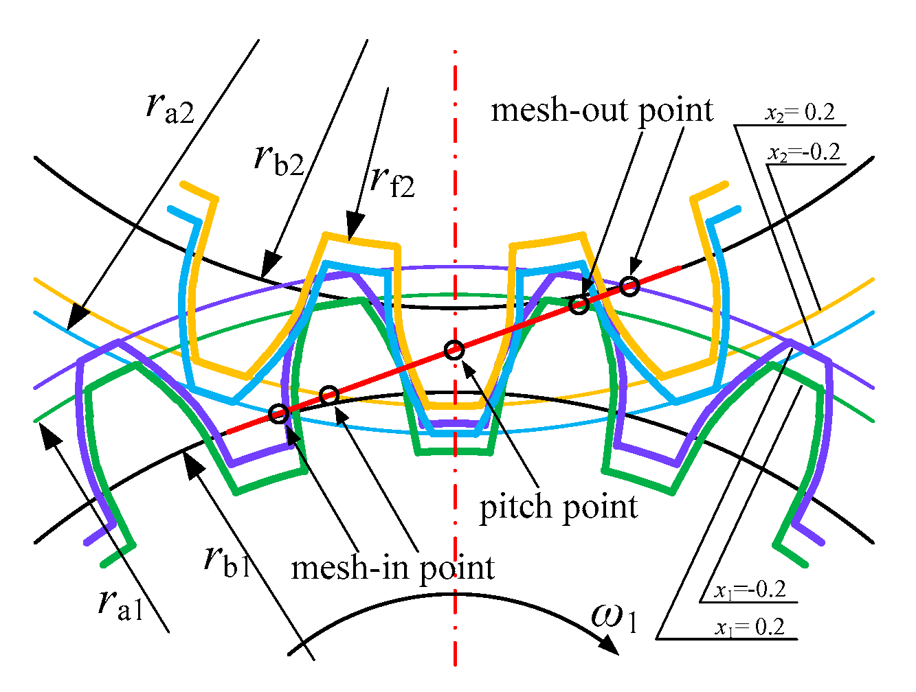
2.3. The Helical Gear with Addendum Modification

The helical gear with addendum modification is the result of the cutter deviation from the normal position. When the cutter nears the gear center, the addendum modification coefficient xm is negative, and the tooth thickness decreases, and vice versa when the cutter is far from the gear center, as shown in Figure 7.
According to the geometric characteristics of a helical gear with addendum modification, the radius of the tip ra, the radius of the root rf and the tooth thickness s could be calculated by the following formulas:
{ r a = 1 2 m n cos β z + ( h an + x m Δ y n ) m n r f = 1 2 m n cos β z + ( h an + c n x m ) m n s = ( π 2 + 2 x m c o s β tan α tc ) m n cos β
where xm denotes the addendum modification coefficient; β denotes the helical angle; αtc denotes the transverse pressure angle; mn denotes the normal module; z denotes the tooth number; han and can denote the addendum factor and tip clearance factor, respectively; Δyn denotes the addendum change coefficient.
From the transverse view, it can be observed that the position of the meshing point is delayed when the driving gear is in positive modification and the driven gear is in negative modification because the tip diameter of the driving gear increases while the tip diameter of the driven gear decreases. It can be predicted that the addendum modification would affect the value but also the phase of mesh stiffness.

3. The Model Validation

The finite element method has the advantages of high accuracy and precision and the disadvantage of calculating time. Thus, to verifying the comprehensive analytical model proposed in this paper is adopted by using two different gear pairs.

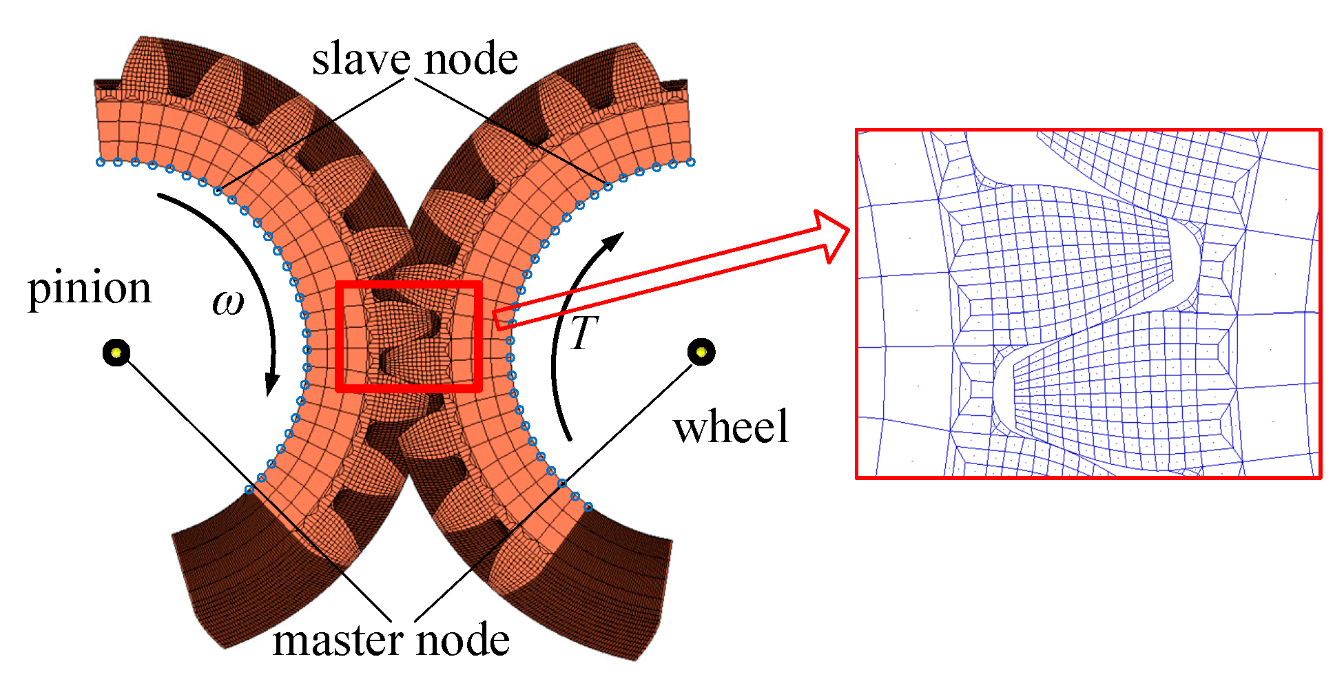
3.1. The Computational Method of the Finite Element Model

A three-dimensional model of a helical gear pair is built with the finite element mesh type of C3D8 in finite element software. The pinion is the driving gear, and the wheel is the driven gear, as shown in Figure 8. The finite element mesh at the gear teeth is densified in order to ensure an accurate calculation and save calculation time. The master points at the center of the wheel and pinion are coupled with the inner ring points of the wheel and pinion, respectively. The master points should be constrained in all degrees of freedom except the direction that rotates around the z-axis. The torque and speed are applied to the master points of the wheel and pinion, respectively. The penalty method is used in the contact analysis. It should be noted that at least ceil(εγ) + 2 teeth should be used in order to avoid the local large deflection during the initial and end mesh in the dynamic analysis. The results should be calculated from the second tooth.
According to the finite element model, the stiffness of the ith tooth surface of the pinion and wheel can be calculated.
K i p = j = 1 n p F j p δ j p , K i w = j = 1 n w F j w δ j w
where F j p , F j w denote the force of the jth node at the ith tooth surface of the pinion and wheel, respectively. δ j p , δ j w denote the deformation of the jth node at the ith tooth surface of the pinion and wheel, respectively. np and nw represent the node number of the ith tooth surface of the pinion and wheel, respectively.
The mesh stiffness of the ith tooth pair can be calculated as
K i = 1 / ( 1 K i p + 1 K i w )
The result calculated by the finite element model can be expressed as
K = i = 1 n K i

3.2. Gear Parameters

In order to verify the universality of this model, two gear pairs parameters were randomly selected to calculate the mesh stiffness by using the model in this paper, and the results are compared with the finite element method. The detailed parameters are shown in Table 1.

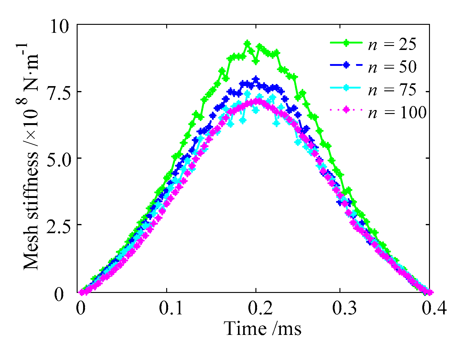
3.3. Finite Element Mesh Sensitive Analysis

The number of finite element meshes affects the calculating time and accuracy. Therefore, the helical gear is divided into n parts along the axial direction when the finite element analysis is carried out. A computer is used with i5 CPU @ 3.20 GHz, RAM 8.00 GB, and 64-bit operating system. The results of n = 25, 50, 75, 100 of gear pair 1# are calculated, respectively. The results show that the higher the finite element mesh density, the smaller the mesh stiffness of the single tooth, and the smaller the error between mesh stiffness curves (as shown in Figure 9). On the contrary, the calculation time is greatly increased. In order to balance the relationship between calculating time and accuracy, the helical gears are divided into 75 parts along the axial direction when the finite element analysis is carried out.

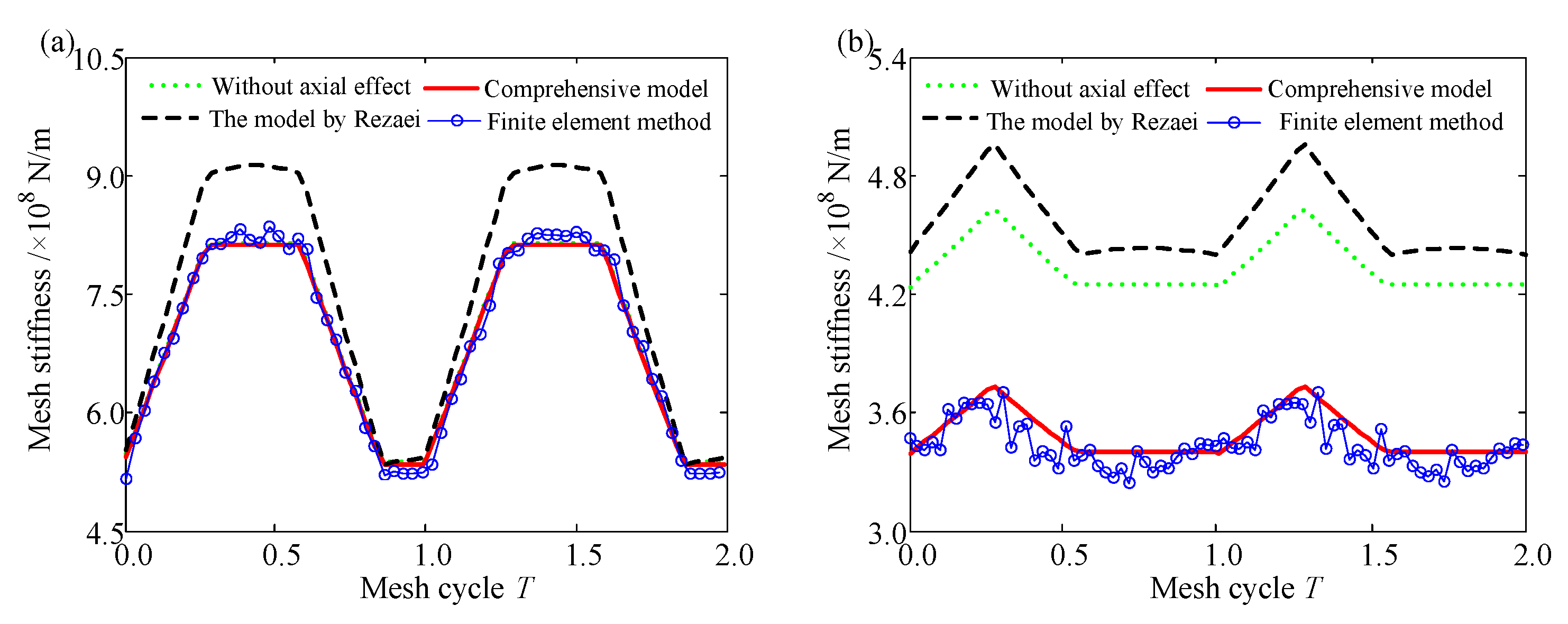
3.4. Stiffness Contrast

The mesh stiffness with the parameters shown in Table 1 is obtained by adopting the comprehensive analytical model and using the finite element model. More precisely, the mesh stiffness with or without the axial effect is calculated.
The results obtained by the analytical model in this paper are consistent with the finite element model. The errors of the mean value, maximum value, and minimum value between the two models do not exceed 5% in a meshing cycle, as shown in Table 2. This indicates that the comprehensive model is reasonable and accurate. Compared with the model in Ref. [24], which does not take the slice coupling, structure coupling, or effect of axial mesh force into account, the mesh stiffness obtained by the analytical method in a multitooth engagement region is smaller. Because the deformation of the fillet-foundation will increase when the coupling effect is considered, the stiffness of the fillet-foundation and the mesh stiffness will decrease. Another phenomenon is that the axial mesh force has a greater influence on the mesh stiffness of gear pair 2 than gear pair 1, because the helical angle of gear pair 2 is large than that of gear pair 1, which increases the axial component of the mesh force and the axial deformation of the fillet-foundation and tooth, so the mesh stiffness is small. The mesh stiffness of gear pair 1 is larger than that of gear pair 2 because gear pair 2 has a small face width. The duration time of the engagement region with fewer teeth is different from that of the multitooth engagement region in a mesh cycle because the contact ratio is different, as shown in Figure 10.
The finite element model of gear pair 1# to obtain the mesh stiffness with element type C3D8R and element number 73,964 needs about 12 h; in contrast, the analytical method only needs no more than 1 min.

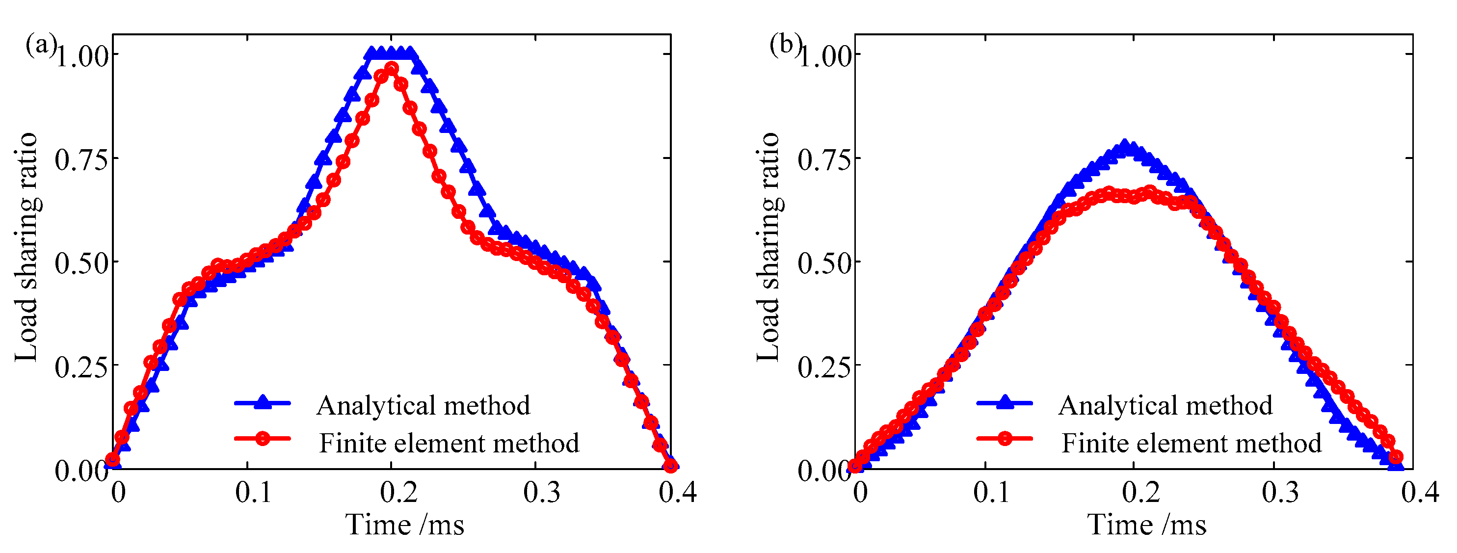
3.5. Load Sharing Ratio Contrast

The load sharing ratio can be defined as
L r = F t 1 / F t
where Ft1 denotes the load undertaken by one gear tooth, and Ft denotes the transverse mesh force.
The load sharing ratio obtained by the analytical model is consistent with that of the finite element model. This result further verifies that the analytical method in this paper is accurate. The maximum load sharing ratio of gear pair 1 equals one; in contrast, that of gear pair 2 is less than 1. This is because the contact ratio of gear pair 1 equals 1.8379, which indicates that the number of teeth in the engagement region switches from 1 to 2 (Figure 11), and there exists a situation where a single tooth bears the load alone. However, there are at least two teeth bearing the load simultaneously for gear pair 2 (Figure 12). The duration time of the engagement region with fewer teeth calculated by the finite element model is less than that calculated by the analytical model, because the deformation in the single-tooth engagement region causes the next tooth to enter the engagement region earlier, but this phenomenon is ignored by the analytical method, as shown in Figure 13.

4. Results and Discussion

Based on the above analytical model, some results are calculated in this section. It should be mentioned that the position angle of the driving gear in the following figures is defined as zero at the connecting line of the gear center and is positive along the direction of driving speed.

4.1. Helical Angle

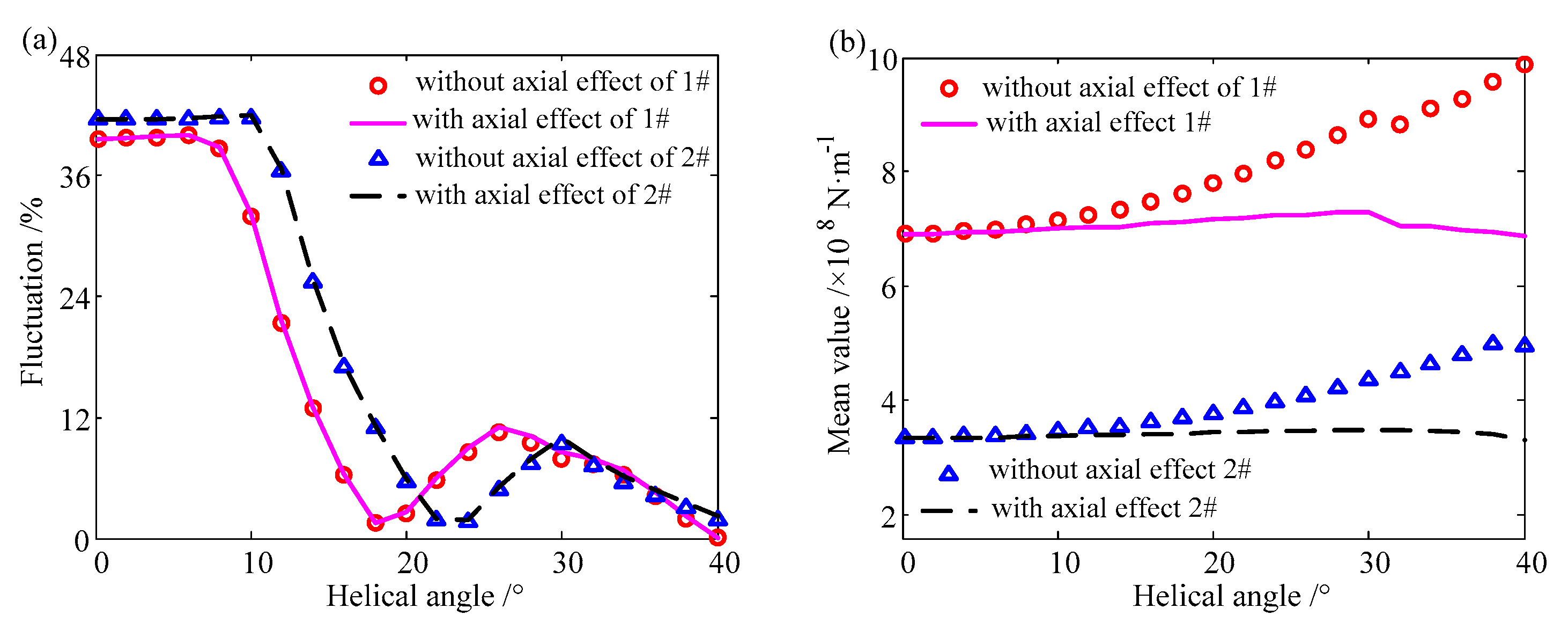
4.1.1. The Influence of Helical Angle on Mesh Stiffness

It can be found that the axial component of mesh force has a slight influence on the fluctuation of the mesh stiffness. With an increasing helical angle, the fluctuation curves indicate a wave-like downward trend. The fluctuation value approaches the minimum value when the overlap contact ratio is close to an integer, as shown in Figure 14a. The mean value increases when the axial force not considered, because the larger the helical angle, the more teeth enter the engagement region. The mean value is unchanged when the axial force is considered. More teeth enter the engagement region when the helical angle is increasing. At the same time, the axial component of the mesh force will increase when the helical angle increases, which leads to a deformation caused by the decrease in axial mesh force, and to a decrease in mesh stiffness. That is, one factor will enhance the mesh stiffness, while the other will reduce it. Consequently, the mesh stiffness remains unchanged when the two factors are coupled. As a result, the influence of the axial component of mesh force on mesh stiffness does not exceed 10% if the helical angle is less than 20°, while the influence increases significantly when the helical angle is more than 20°, as shown in Figure 14b.

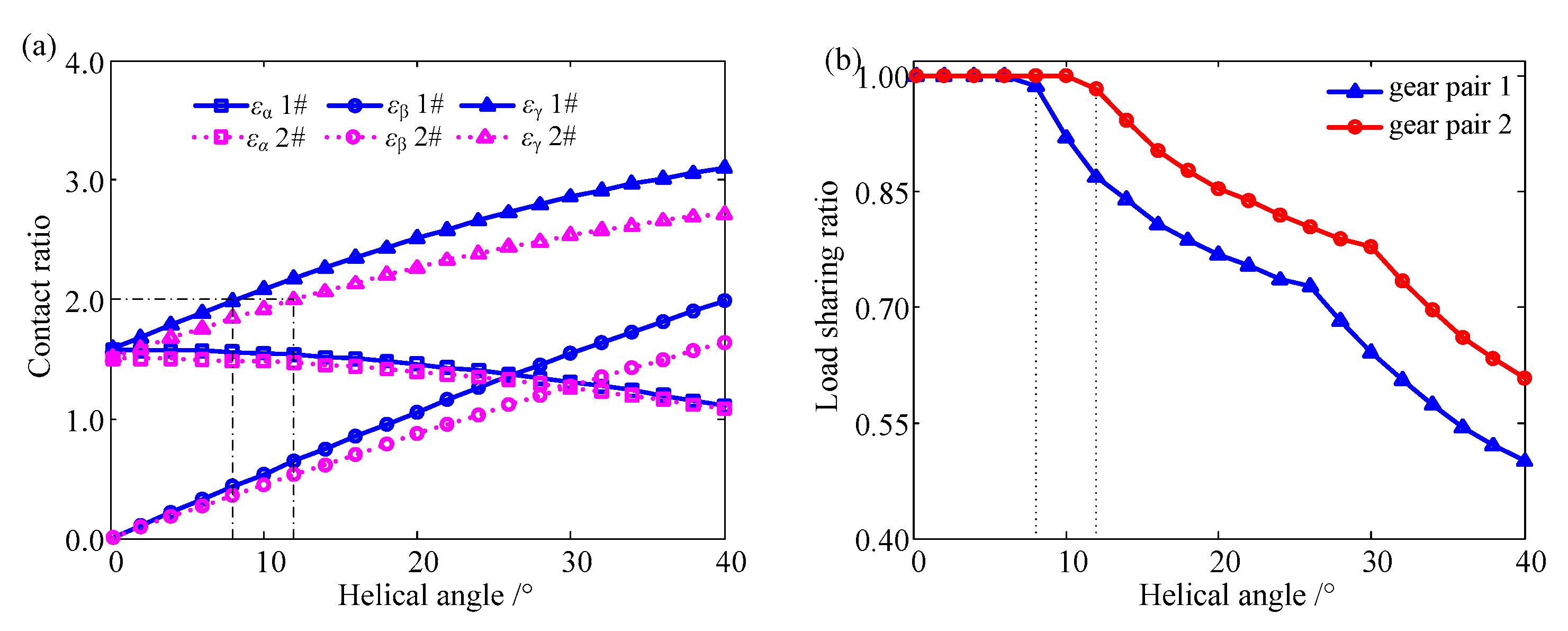
4.1.2. The Influence of Helical Angle on the Load Sharing Ratio

As the helical angle is relatively small, the maximum value of the load sharing ratio equals one (as shown in Figure 15a). This indicates that there exists a situation where a single tooth bears the load alone. As the helical angle increases, the maximum value of the load sharing ratio decreases. Because two or more teeth will enter the engagement region simultaneously, the maximum value of the load sharing ratio will decrease, as shown in Figure 15b.

4.2. Addendum Modification Coefficient

To investigate the influence of addendum modification on mesh stiffness, three groups of addendum modification coefficients are assumed, as shown in Table 3. Case 1 in Table 3 is the sum of addendum modification coefficients equal to zero; that is, the center distance remains constant relative to the standard case. Case 2 is the sum of addendum modification coefficients greater than the standard case, which indicates that the driving gear and the driven gear are far apart. Case 3 is opposite to Case 2.

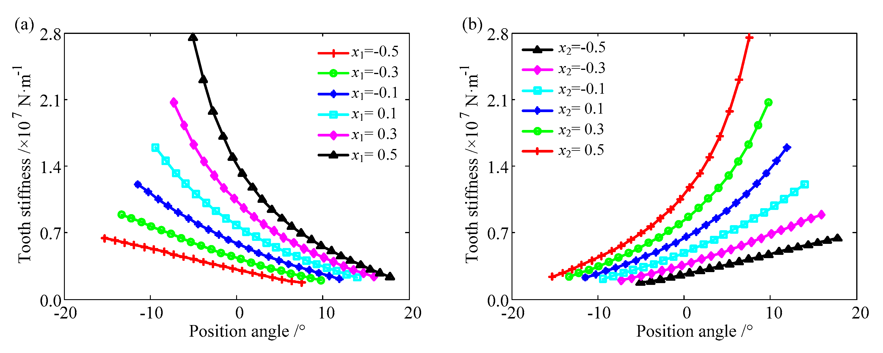
4.2.1. The Influence on Stiffness

The influences of the addendum modification coefficient on the tooth stiffness of the sliced gear are studied by using the parameters of Case 1, as shown in Figure 16. Attention should be paid to the position angle of the x-axis, which represents the whole mesh process. A negative value indicates that the meshing point has not reached the pitch point, and a positive value indicates that the meshing point has exceeded the pitch point.
In the whole mesh process, the tooth stiffness curves of the sliced gear of a driving gear show a downward trend. The tooth stiffness of the sliced gear decreases gradually. Because the mesh point moves from the root to the top along the tooth profile, and the tooth thickness decreases, the tooth compliance of the sliced gear increases. The opposite is true for the driven gear. With an increasing addendum modification coefficient of the driving gear, that of the driven gear decreases, and the tooth stiffness curve moves to the positive x-direction, which indicates that the position of the meshing point is delayed because the tip diameter of the driving gear increases while the tip diameter of the driven gear decreases. With an increasing addendum modification coefficient, the tooth stiffness curves of the sliced gear of both the driving and driven gears move upward. Because the cutter is far from the gear center when positive addendum modification is adopted, the tooth thickness increases, which leads to an increase in stiffness. The change in tooth stiffness of the sliced gear increases with an increasing addendum modification coefficient when the tooth root bears the load, because the increasing addendum modification coefficient causes the thickness of the tooth root to increase. Another reason is that the tooth is considered as a cantilever beam whose root is fixed. The combination of these two reasons leads to high stiffness.
In the whole mesh process, there are “bulge” phenomena in the middle part of the fillet-foundation stiffness curve of the sliced gear, because the two ends belong to the double-tooth engagement region, and the structure coupling leads to a large deformation of the fillet-foundation and low stiffness. With an increasing addendum modification coefficient, the fillet-foundation stiffness curves of the sliced gear of both the driving and driven gears move upward, because the root diameter becomes large and the normal component of the mesh force on the tooth surface changes, leading to an increase in the fillet-foundation stiffness of the sliced gear, as shown in Figure 17.
The tooth stiffness of the helical gear can be acquired by superposing the tooth stiffness of the sliced gear along the centerline of the gear. The sketch of superposition is shown in Figure 18.
Due to the existence of a helical angle, the tooth stiffness curve of the sliced gear lagging in the engagement region is on the right side of the former one. By superposing the tooth stiffness of the sliced gear, the tooth stiffness of the helical gear appears to increase first and then decrease. As the addendum modification coefficient increases, the maximum value of the tooth stiffness of the helical gear increases. Because the tooth stiffness of the helical gear is calculated by superposing all the tooth stiffness of the sliced gear, the larger the addendum modification coefficient, the greater the tooth stiffness of each sliced gear and the greater it will be after superposition, as shown in Figure 19.

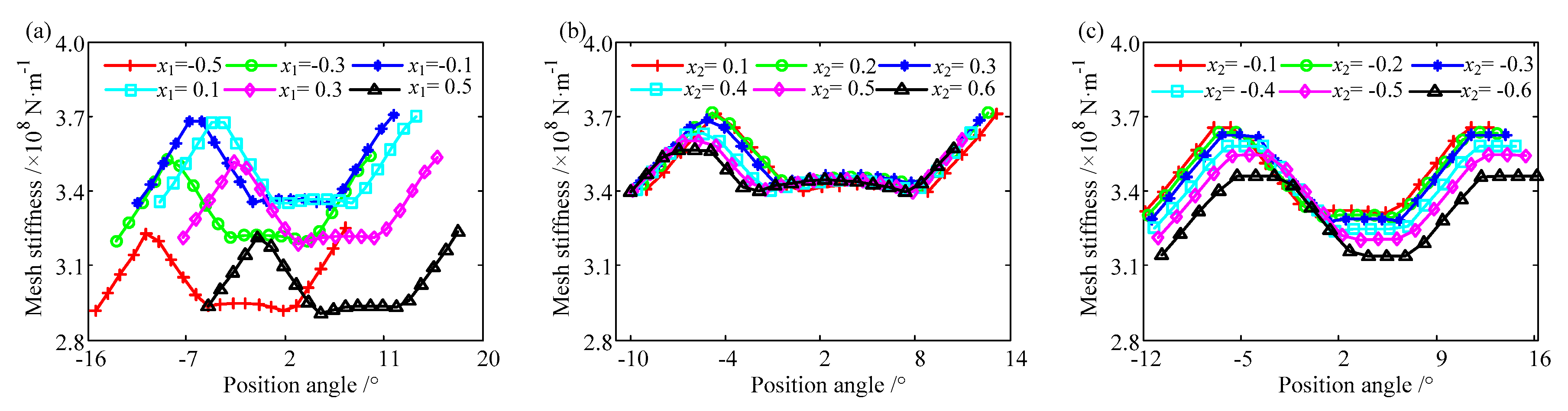
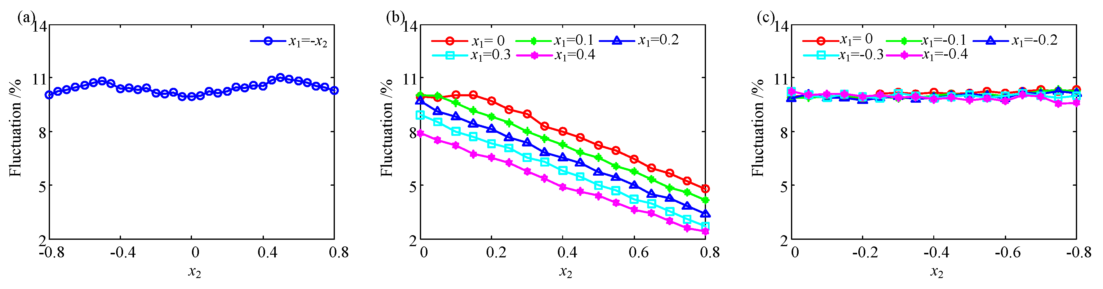
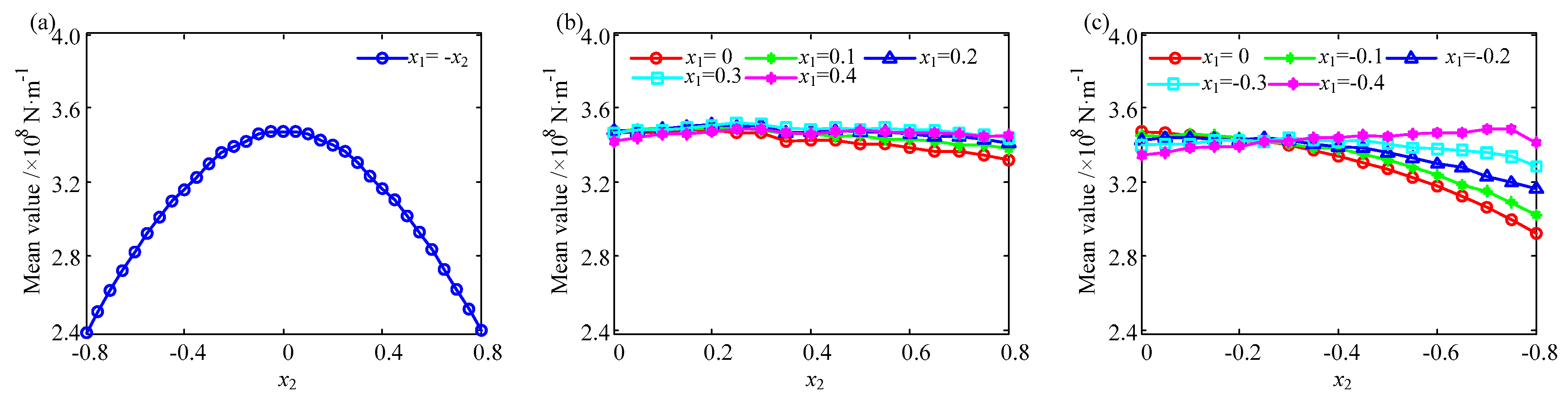
4.2.2. The Influence on Mesh Stiffness

The relationship between the mesh stiffness of the helical gear and the addendum modification coefficient given in Table 3 is studied. It can be found that in the whole mesh process, with an increasing addendum modification coefficient of the driving gear (Case 1), the driven gear decreases, the mesh stiffness curve increases first and then decreases while moving toward the positive of the x-direction. For Case 2, in which the positive coefficient is adopted in the driving and driven gears, the mesh stiffness curve is unchanged with the different coefficients. For Case 3, in which the negative coefficient is adopted, the mesh stiffness curve decreases slightly with an increasing absolute value of the negative coefficient, as shown in Figure 20.
The fluctuation value and mean value of mesh stiffness in a mesh period can be obtained. For Case 1 with x1 + x2 = 0, the fluctuation value of mesh stiffness is always approximately 10%, and the mean value increases first and then decreases; the maximum of the mean value is 3.5 × 10⁸ N/m with x1 = x2 = 0, and the minimum value is 2.4 × 10⁸ N/m with x1 = −x2 = 0.8 or x1 = −x2 = −0.8. For Case 2 with x1 > 0 and x2 > 0, with an increasing addendum modification coefficient, the fluctuation value decreases from 10% to 2%, which indicates that the larger the positive modification, the smaller the fluctuation value. The mean value of mesh stiffness for Case 2 remains approximately 3.5 × 10⁸ N/m. For Case 3 with x1 < 0 and x2 < 0, the fluctuation value remains unchanged at approximately 10%, as shown in Figure 21 and Figure 22. Synthetically speaking, adopting a positive coefficient for the driving and driven gears is good for reducing the fluctuation of mesh stiffness.

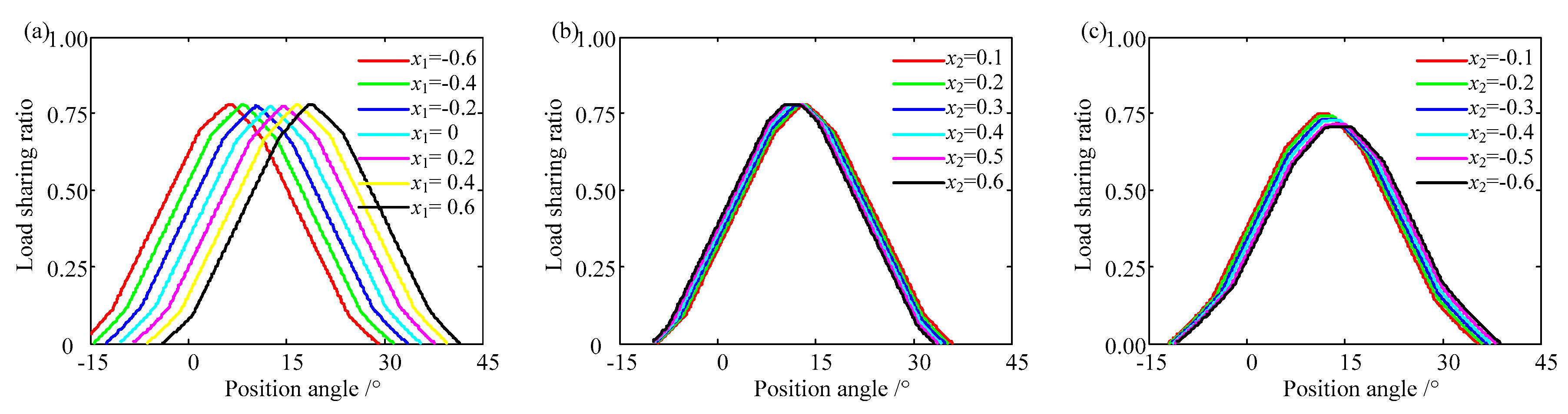
4.2.3. The Influence on the Load Sharing Ratio

The relationship between the load sharing ratio and addendum modification is studied. It can be easily found that the load sharing ratio curves increase first and then decrease. This is because as the gear rotates, the gear tooth takes increasingly more of the load until it reaches the maximum value, and then the load sharing ratio decreases with the tooth exiting the engagement region. The maximum value of the load sharing ratio is less than one because there are at least two teeth in the engagement region with the contact ratio exceeding 2. For Case 1 with x1 + x2 = 0, the load sharing ratio curve with x1 = −x2 = −0.6 is on the left side of the curve with x1 = x2 = 0, and the curve with x1 = −x2 = 0.6 is on the right side of the curve with x1 = x2 = 0. That is, the phase of mesh stiffness is ahead of the standard gear when the driving gear is in positive modification and the driven gear is in negative modification. For Case 2 with x1 > 0 and x2 > 0, the load sharing ratio curves are almost the same. This indicates that a positive addendum modification has a slight effect on the load sharing ratio. For Case 3 with x1 < 0 and x2 < 0, the maximum value of the load sharing ratios decreases slightly because the contact ratio increases when the negative coefficient is applied, as shown in Figure 23.

5. Conclusions

A comprehensive mathematical model for calculating the mesh stiffness of a helical gear with addendum modification is established. The results obtained by the comprehensive analytical model are consistent with that of the finite element model, but only several seconds are needed by using the analytical method in this paper. The main conclusions include the following:
(1)
The mesh stiffness of a helical gear will be decreased in multiteeth regions caused by the structure coupling. The more teeth involved, the greater the influence of structure coupling is.
(2)
The axial component of mesh force affects the mesh stiffness of the helical gear. It should not be ignored when an accurate calculation of mesh stiffness is carried out.
(3)
The fluctuation value of mesh stiffness decreases when a positive addendum modification coefficient is adopted. The addendum modification also changes the phase of mesh stiffness.
Time-varying mesh stiffness is an important internal excitation source when the dynamic analysis of a gear transmission system is executed. Therefore, the fluctuation of mesh stiffness has a significant effect on the vibration of gear systems. Based on the comprehensive analytical model established in this study, the accuracy value of mesh stiffness could be obtained quickly. The dynamic response results, such as the vibration displacement and vibration acceleration of gear transmission, could be obtained by carrying out a dynamic analysis. The detailed study would be carried out in the following research.

Author Contributions

Methodology, formal analysis, validation, writing—original draft preparation, S.H.; conceptualization, writing—review and editing, J.W.; software, A.Z., C.Z. and J.Y.; writing—review and editing, C.W. All authors have read and agreed to the published version of the manuscript.

Funding

This research was funded by the National Natural Science Foundation of China, grant number 51775058, the National Key R&D Program of China, grant number 2018YFB2001602, and the Fundamental Research Funds for the Central Universities of China, grant number 2020CDCGJX030.

Acknowledgments

The authors would like to gratefully acknowledge the National Natural Science Foundation of China (No. 51775058), the National Key R&D Program of China [No. 2018YFB2001602], and the Fundamental Research Funds for the Central Universities of China (No. 2020CDCGJX030) for their support. Finally, the authors would like to thank the editors and reviewers for their valuable comments and constructive suggestions.

Conflicts of Interest

The authors declare no conflict of interest.

References

  1. Abousleiman, V.; Velex, P. A Hybrid 3D Finite Element/Lumped Parameter Model for Quasi-Static and Dynamic Analyses of Planetary/Epicyclic Gear Sets. Mech. Mach. Theory 2006, 41, 725–748. [Google Scholar] [CrossRef]
  2. Hou, S.; Wei, J.; Zhang, A.; Lim, T.C.; Zhang, C. Study of Dynamic Model of Helical/Herringbone Planetary Gear System with Friction Excitation. J. Comput. Nonlinear Dyn. 2018, 13, 121007. [Google Scholar] [CrossRef]
  3. Han, J.; Shin, J.; Kim, J.; Oh, S. Design 2 Speed Transmission for Compact Electric Vehicle Using Dual Brake System. Appl. Sci. 2019, 9, 1793. [Google Scholar] [CrossRef] [Green Version]
  4. Wang, J.; Yang, S.; Liu, Y.; Mo, R. Analysis of Load-Sharing Behavior of the Multistage Planetary Gear Train Used in Wind Generators: Effects of Random Wind Load. Appl. Sci. 2019, 9, 5501. [Google Scholar] [CrossRef] [Green Version]
  5. Guo, Y.; Parker, R.G. Dynamic Modeling and Analysis of a Spur Planetary Gear Involving Tooth Wedging and Bearing Clearance Nonlinearity. Eur. J. Mech. A/Solids 2010, 29, 1022–1033. [Google Scholar] [CrossRef]
  6. Xiong, Y.; Huang, K.; Xu, F.; Yi, Y.; Sang, M.; Zhai, H. Research on the Influence of Backlash on Mesh Stiffness and the Nonlinear Dynamics of Spur gears. Appl. Sci. 2019, 9, 1029. [Google Scholar] [CrossRef] [Green Version]
  7. Yuan, B.; Liu, G.; Liu, L. Quasi-Static Characteristics and Vibration Responses Analysis of Helical Geared Rotor System with Random Cumulative Pitch Deviations. Appl. Sci. 2020, 10, 4403. [Google Scholar] [CrossRef]
  8. Munro, R.G.; Palmer, D.; Morrish, L. An Experimental Method to Measure Gear Tooth Stiffness throughout and Beyond the Path of Contact. Proc. Inst. Mech. Eng. Part C J. Mech. Eng. Sci. 2001, 215, 793–803. [Google Scholar] [CrossRef]
  9. Raghuwanshi, N.K.; Parey, A. A New Technique of Gear Mesh Stiffness Measurement Using Experimental Modal Analysis. J. Vib. Acoust. 2019, 141, 021018. [Google Scholar] [CrossRef]
  10. Lei, X.; Gao, Z.; Cui, J.; Wang, H.; Wang, S. The Minimum Zone Evaluation for Elliptical Profile Error Based on the Geometry Optimal Approximation Algorithm. Measurement 2015, 75, 284–288. [Google Scholar]
  11. Karpat, F.; Yuce, C.; Dogan, O. Experimental Measurement and Numerical Validation of Single Tooth Stiffness for Involute Spur Gears. Measurement 2020, 150, 107043. [Google Scholar] [CrossRef]
  12. Zhan, J.; Fard, M.; Jazar, R. A CAD-FEM-QSA Integration Technique for Determining the Time-Varying Meshing Stiffness of Gear Pairs. Measurement 2017, 100, 139–149. [Google Scholar] [CrossRef]
  13. Li, J.; Xu, M.; Wang, S. Finite Element Analysis of Instantaneous Mesh Stiffness of Cylindrical Gears (With and Without Flexible Gear Body). Commun. Numer. Methods Eng. 1999, 15, 579–587. [Google Scholar] [CrossRef]
  14. Wang, J.; Howard, I. The Torsional Stiffness of Involute Spur Gears. Proc. Inst. Mech. Eng. Part C J. Mech. Eng. Sci. 2004, 218, 131–142. [Google Scholar] [CrossRef]
  15. Wei, J.; Zhang, A.; Wang, G.; Qin, D.; Lim, T.C.; Wang, Y.; Lin, T. A Study of Nonlinear Excitation Modeling of Helical Gears with Modification: Theoretical Analysis and Experiments. Mech. Mach. Theory 2018, 128, 314–335. [Google Scholar] [CrossRef]
  16. Yang, D.C.H.; Lin, J.Y. Hertzian Damping Tooth Friction and Bending Elasticity in Gear Impact Dynamics. J. Mech. Transm. Autom. Des. 1987, 109, 189–196. [Google Scholar] [CrossRef]
  17. Wu, S.; Zuo, M.J.; Parey, A. Simulation of Spur Gear Dynamics and Estimation of Fault Growth. J. Sound Vib. 2008, 317, 608–624. [Google Scholar] [CrossRef]
  18. Liu, S.; Song, C.; Zhu, C.; Liang, C.; Yang, X. Investigation on The Influence of Work Holding Equipment Errors on Contact Characteristics of Face-Hobbed Hypoid Gear. Mech. Mach. Theory 2019, 138, 95–111. [Google Scholar] [CrossRef]
  19. Sainsot, P.; Velex, P.; Duverger, O. Contribution of Gear Body to Tooth Deflections-A New Bidimensional Analytical Formula. J. Mech. Des. 2004, 126, 748–752. [Google Scholar] [CrossRef]
  20. Chen, Z.; Shao, Y. Dynamic Simulation of Spur Gear with Tooth Root Crack Propagating Along Tooth Width and Crack Depth. Eng. Fail. Anal. 2011, 18, 2149–2164. [Google Scholar] [CrossRef]
  21. Ma, H.; Zeng, J.; Feng, R.; Pang, X.; Wen, B. An Improved Analytical Method for Mesh Stiffness Calculation of Spur Gears with Tip Relief. Mech. Mach. Theory 2016, 98, 64–80. [Google Scholar] [CrossRef]
  22. Xie, C.; Hua, L.; Han, X.; Lan, J.; Wan, X.; Xiong, X. Analytical Formulas for Gear Body-Induced Tooth Deflections of Spur Gears Considering Structure Coupling Effect. Int. J. Mech. Sci. 2018, 148, 174–190. [Google Scholar] [CrossRef]
  23. Wang, Q.; Zhao, B.; Fu, Y.; Kong, X.; Ma, H. An Improved Time Varying Mesh Stiffness Model for Helical Gear Pairs Considering Axial Mesh Force Component. Mech. Syst. Signal Process. 2018, 106, 413–429. [Google Scholar] [CrossRef]
  24. Rezaei, M.; Poursina, M.; Jazi, S.H.; Aboutalebi, F.H. Calculation of Time Dependent Mesh Stiffness of Helical Planetary Gear System Using Analytical Approach. J. Mech. Sci. Technol. 2018, 32, 3537–3545. [Google Scholar] [CrossRef]
  25. Seager, D.L. Tooth Loading and Static Behavior of Helical Gears. ASLE Trans. 1970, 13, 66–77. [Google Scholar] [CrossRef]
  26. Yu, W.; Mechefske, C.K.; Timusk, M. Influence of the Addendum Modification on Spur Gear Back Side Mesh Stiffness and Dynamics. J. Sound Vib. 2017, 389, 183–201. [Google Scholar] [CrossRef]
  27. Ma, J.; Liu, T.; Zha, C.; Song, L. Simulation Research on the Time Varying Meshing Stiffness and Vibration Response of Micro-Cracks in Gears under Variable Tooth Shape Parameters. Appl. Sci. 2019, 9, 1512. [Google Scholar] [CrossRef] [Green Version]
  28. Hedlund, J.; Lehtovaara, A. A Parameterized Numerical Model for the Evaluation of Gear Mesh Stiffness Variation of a Helical Gear Pair. Proc. Inst. Mech. Eng. Part C J. Mech. Eng. Sci. 2008, 222, 1321–1327. [Google Scholar] [CrossRef]
Figure 1. The relationship between neighboring sliced gears.
Applsci 10 06695 g001
Figure 2. The decomposition sketch of mesh force of a helical gear.
Applsci 10 06695 g002
Figure 3. The sketch of the tooth with the axial mesh force.
Applsci 10 06695 g003
Figure 4. The sketch of the tooth with the transverse mesh force.
Applsci 10 06695 g004
Figure 5. The sketch of the fillet-foundation with the axial mesh force.
Applsci 10 06695 g005
Figure 6. The sketch of the fillet-foundation with the transverse mesh force (a) single tooth in engagement (b) double teeth in engagement.
Applsci 10 06695 g006
Figure 7. The sketch of the helical gear with addendum modification (transverse view).
Applsci 10 06695 g007
Figure 8. The finite element model.
Applsci 10 06695 g008
Figure 9. The mesh stiffness of single tooth pair with different number of finite element mesh.
Applsci 10 06695 g009
Figure 10. The mesh stiffness of different parameters (a) gear pair 1 and (b) gear pair 2.
Applsci 10 06695 g010
Figure 11. The sketch of the contacting force of gear pair 1. (a) Two teeth in engagement region, (b) one tooth in engagement region.
Applsci 10 06695 g011
Figure 12. The sketch of the contacting force of gear pair 2. (a) Three teeth in engagement region, (b) two teeth in engagement region.
Applsci 10 06695 g012
Figure 13. The load sharing ratio of (a) gear pair 1 and (b) gear pair 2.
Applsci 10 06695 g013
Figure 14. The influence of the helical angle on the (a) fluctuation of mesh stiffness and (b) mean value of mesh stiffness.
Applsci 10 06695 g014
Figure 15. The influence of helical angle on (a) contact ratio and (b) maximum load sharing ratio.
Applsci 10 06695 g015
Figure 16. The tooth stiffness of the sliced gear with the parameters of Case 1. (a) Driving gear, (b) driven gear.
Applsci 10 06695 g016
Figure 17. The fillet-foundation stiffness of the sliced gear with parameters of Case 1. (a) Driving gear, and (b) driven gear.
Applsci 10 06695 g017
Figure 18. The stiffness by axial superposition. (a) Superposition principle, (b) superposition result.
Applsci 10 06695 g018
Figure 19. The tooth stiffness of the helical gear with the parameters of Case 1. (a) Driving gear, (b) driven gear.
Applsci 10 06695 g019
Figure 20. The mesh stiffness of the helical gear. (a) x1 + x2 = 0, (b) x1 = 0.2, (c) x1 = −0.2.
Applsci 10 06695 g020
Figure 21. The influence of addendum modification on the fluctuation. (a) Case 1, (b) Case 2, (c) Case 3.
Applsci 10 06695 g021
Figure 22. The influence of addendum modification on the mean value. (a) Case 1, (b) Case 2, (c) Case 3.
Applsci 10 06695 g022
Figure 23. The load sharing ratio. (a) x1 + x2 = 0, (b) x1 = 0.2, (c) x1 = −0.2.
Applsci 10 06695 g023
Table 1. The detailed parameters.
No.Items1#2#
1gearPinionWheelPinionWheel
2Normal module mn (mm)3.53.522
3Pressure angle α (°)20202020
4Number of teeth20302020
5Face width b (mm)34341616
6Helix angle β (°)553030
7Profile shift coefficient0.1798−0.13210.07950.0795
8Addendum coefficient1111
9Tip clearance coefficient0.250.250.250.25
10hub bore radius rint (mm)22381515
11Center distance (mm)8846.5
12Contact ratio εαβγ1.5684/0.2695/1.83791.2625/1.2732/2.5357
Table 2. The mesh stiffness obtained by different models (×108 N/m).
1#2#
Max ValueMin ValueMean ValueMax ValueMin ValueMean Value
Analytical method in this paper8.07455.29166.93673.73933.38463.4810
Finite element method8.17985.23146.95533.60433.35643.4357
Error (%)1.291.150.273.750.841.32
Table 3. Addendum modification coefficient.
Case 1 (x1 + x2 = 0)Case 2 (x1 + x2 > 0)Case 3 (x1 + x2 < 0)
x1x2x1x2x1x2
−0.8~0.80.8~−0.80.10~0.8−0.10~−0.8
0.20~0.8−0.20~−0.8
0.30~0.8−0.30~−0.8
0.40~0.8−0.40~−0.8

