Article

Precoded Generalized Spatial Modulation for Downlink MIMO Transmissions in Beyond 5G Networks

1
Department of Information Science and Technology, ISCTE—Instituto Universitário de Lisboa, Av. das Forças Armadas, 1649-026 Lisbon, Portugal
2
Radio Systems Group, Instituto de Telecomunicações, Av. Rovisco Pais, 1049-001 Lisbon, Portugal
*
Author to whom correspondence should be addressed.
Appl. Sci. 2020, 10(18), 6617; https://doi.org/10.3390/app10186617
Submission received: 20 August 2020 / Revised: 14 September 2020 / Accepted: 16 September 2020 / Published: 22 September 2020
(This article belongs to the Special Issue Transmission Techniques for 5G and Beyond)

Abstract

:
The design of multiple input multiple output (MIMO) schemes capable of achieving both high spectral and energy efficiency constitutes a challenge for next-generation wireless networks. MIMO schemes based on generalized spatial modulations (GSM) have been widely considered as a powerful technique to achieve that purpose. In this paper, a multi-user (MU) GSM MIMO system is proposed, which relies on the transmission of precoded symbols from a base station to multiple receivers. The precoder’s design is focused on the removal of the interference between users and allows the application of single-user GSM detection at the receivers, which is accomplished using a low-complexity iterative algorithm. Link level and system level simulations of a cloud radio access network (C-RAN) comprising several radio remote units (RRUs) were run in order to evaluate the performance of the proposed solution. Simulation results show that the proposed GSM MU-MIMO approach can exploit efficiently a large number of antennas deployed at the transmitter. Moreover, it can also provide large gains when compared to conventional MU-MIMO schemes with identical spectral efficiencies. In fact, regarding the simulated C-RAN scenario with perfect channel estimation, system level results showed potential gains of up to 155% and 139% in throughput and coverage, respectively, compared to traditional cellular networks. The introduction of imperfect channel estimation reduces the throughput gain to 125%.

1. Introduction

Considering the technological advances over the last decades, the next generation of wireless communications is expected to follow this trend with a significant increase in system robustness (SR), spectral efficiency (SE) and energy efficiency (EE). In recent years, new emerging techniques have appeared in order to meet the increasingly challenging requirements of beyond fifth generation (B5G) communication systems, such as non-orthogonal multiple access (NOMA) schemes like Signaling Aided Sparse Code Multiple Access [1] or index modulations (IM). IM has received significant attention due to its ability to activate a subset of certain elements of communication resources, namely antennas, subcarriers, and slots [2,3]. Generalized spatial modulation (GSM) constitutes a particular case of IM, which is suitable for large scale multiple input multiple output (MIMO) antennas schemes enabling greater EE with ease of implementation [4,5]. Considering that the information is encoded in the combination of active antennas and, also in the modulated symbols transmitted in the active antennas, GSM can also achieve a greater SE than single antenna communications.
GSM can be considered as a compromise between conventional MIMO and simple radio frequency (RF) transmissions, since only a subset of the available transmission antennas is active for a certain period of time, thus reducing the number of RF chains required. Several detectors have been reported in the literature for single user scenarios. The authors of [6] proposed a minimal average square block error detector (OB-MMSE) that can achieve a close to optimal performance, while its required complexity is much lower when compared to other detectors. This detector uses an algorithm that sorts the possible transmit antenna combinations (TAC), followed by the detection in sequence of the possible signal vector for each TAC using block minimum mean square error (MMSE). A termination threshold must be applied in order to reduce the number of tested TACs. Although this detector is able to achieve near-optimal performance, it can incur in substantial complexity in large scenarios. A different GSM iterative detector is proposed in [7], which is based on dividing the problem of the maximum likelihood detection (MLD) into a sequence of simpler steps, such as the minimization of the unrestricted Euclidean distance, the projection of the elements onto the signal constellation and the projection onto the set of valid active antenna combinations. This approach allows a substantial complexity reduction when compared with the optimal MLD while still achieving near-optimal performance.
Although the wide range of precoding schemes referred to in the literature for MIMO systems considering both uplink and downlink scenarios [8,9,10,11,12], there is a significant imbalance between the number of approaches aimed at those scenarios for GSM-based schemes. In fact, there are very few studies that have extended the use of GSM to downlink MU [13].
Despite describing a system for scalable video broadcast communications in [3], the proposed scheme also considered the use of GSM for multiple users. However, the removal of inter-user interference is made at the receiver, which demands a large number of antennas at the users. A better suited alternative for dedicated links relies on removing inter-user interference at the transmitter through a precoder. This approach is often applied for conventional MU-MIMO as presented in [14], where the authors describe a precoder that accomplishes block diagonalization (BD) of the equivalent channel matrix. The proposed BD precoding guarantees zero inter-user interference and can be thought of as a generalization of channel inversion. Despite the similarity of the approach proposed by the authors in [15], their method cannot only provide improved bit error rate (BER) and throughput performances, but also additional diversity gain by adopting a partial nulling technique for the generalized block diagonalization (GBD). A few precoded schemes have been introduced for spatial modulations (SM) and GSM since then. A new precoder scheme for the downlink of MU-SM systems was proposed in [16], which exploits the channel status information (CSI) at the base station (BS). Here, a precoding matrix is computed, which allows the MU downlink system to be broken down into several independent single user SM systems. A precoded scheme designed for multi-user (MU) GSM systems was reported in [17], with the aim of eliminating all inter-user interference while maintaining the antenna selection features of GSM, which means that only some of the antennas are active, while the rest are silenced. Both proposals of [16,17] are limited in terms of spectral efficiency, since the first one was only defined for SM, while the later was designed specifically for a version of GSM, where the M-quadrature amplitude modulations (M-QAM) symbols are the same in all active antennas.
CSI is fundamental in channel estimation process in order to enable uplink and downlink transmissions in MIMO systems. However, the channel estimation for downlink transmissions on massive MIMO systems operating at frequency division duplexing (FDD) represents a very complex problem, since it is unfeasible for practical applications [18,19]. Time Division Duplexing (TDD) represents an interesting solution that can be used as alternative in order to overcome the aforementioned problem in context of downlink transmission in FDD systems. Considering the use of TDD mode, it is possible to exploit the channel reciprocity, which allows the estimation of the downlink channel by the base station through the uplink channel information. In the uplink scenario, orthogonal pilot signals are sent from the users to the base station, and based on that, signals at the base station will estimate the CSI to the user equipment (UE). After accomplishing this task, the base station beamforms the downlink data towards the UE. Considering that there is a limited number of orthogonal pilots that can be reused between cells, a pilot contamination issue may appear and become a critical problem for massive MIMO channel estimation [20]. In order to overcome this issue and others, such as the increasing amount of required hardware and computational complexity cost due to use of large number of required antennas in those schemes, several channel estimation algorithms have been developed over last few years [21,22,23]. The success of the channel estimation process affects the performance of massive MIMO schemes [24] and, such as, should also be taken into account in the system evaluation. It is important to highlight that even though we will not cover in this paper, massive MIMO systems such as the GSM schemes addressed here are prone to several hardware impairments such as non-linear distortions from power amplifier, I/Q imbalance, sampling jitter, and finite-resolution quantization in analog digital converters (ADCs) [20]. To reduce the impact of these effects on the overall performance of the system, compensation algorithms can be developed to mitigate the impairments.
Another issue that must be considered with the introduction of 5G and beyond is the extreme densification of the network, which requires an increase in the network capacity [25,26]. Poor cell-edge coverage and throughput are the most limiting factors of 4G cellular radio access network (RAN). Some research has been dedicated to decrease inter-cell interference by base station coordination and coordinated beamforming [27,28]. Coordinated multi-point (CoMP) transmission or reception is one of the key techniques in 5G that mitigates inter-cell interference (ICI) from neighboring cells, providing higher spectral efficiency and coverage. CoMP indeed extends the cell coverage area and improves cell edge throughput. Joint processing coordinated multipoint transmission (JP-CoMP) requires the clustering of neighboring cells and cooperative transmission within each cluster. Clustering algorithms can be static and dynamic, centralized or distributed [29,30]. Static clustering relies on a predetermined fixed base station cluster. Each static clustering algorithm utilizes different strategies to determine the efficient cluster formation. The network then decides on base station clusters. Dynamic clustering adapts to network changes, where the usual methods are designed based on centralized control on the network, which requires extensive information sharing. In our study, we only consider static clustering based on channel state information (CSI). The techniques mentioned above are essential to improve the overall spectral and energy efficiencies and also increase the throughput and coverage gains, when compared to traditional cellular networks [31].
Motivated by the work above, in this paper we provide a study on MU-MIMO systems, where GSM symbols are transmitted simultaneously to multiple users (differences between the proposed approach and a conventional MU-MIMO assumed as reference are shown in Table 1). To increase the SE of the transmission, different modulated symbols are sent on different (virtual) antennas, where high-order M-QAM constellation with sizes reaching M = 1024 symbols are considered. To remove inter-user interference and transform the MU transmission into several independent SU links, a BD precoder is applied at the BS, while a modified and improved version of the low-complexity SU GSM detector presented in [7] is used at the receiver.
The influence of imperfect channel estimation on the performance of this massive MIMO GSM-based system is also analyzed. Link level simulations show that the presented GSM MU-MIMO approach can provide substantial performance gains over conventional MU-MIMO. Additionally, system level simulations show that deployments based on cloud-RAN (C-RAN) comprising several radio remote units (RRUs) can achieve large throughput and coverage gains over traditional cellular networks. The paper is organized as follows: Section 2 presents the model for the MU GSM system, Section 3 presents the transmitter and receiver structure followed by the numerical results obtained in Section 4. Finally, the conclusions are outlined in Section 5.
Notation: Matrices and vectors are denoted by uppercase and lowercase boldface letters, respectively, (.)T and (.)H denote the transpose and conjugate transpose, . is the floor function, ( k N ) denotes the number of combinations of N symbols taken k at a time, and supp(x) returns the set of indices of nonzero elements in x (i.e., the support of x).

2. System Model

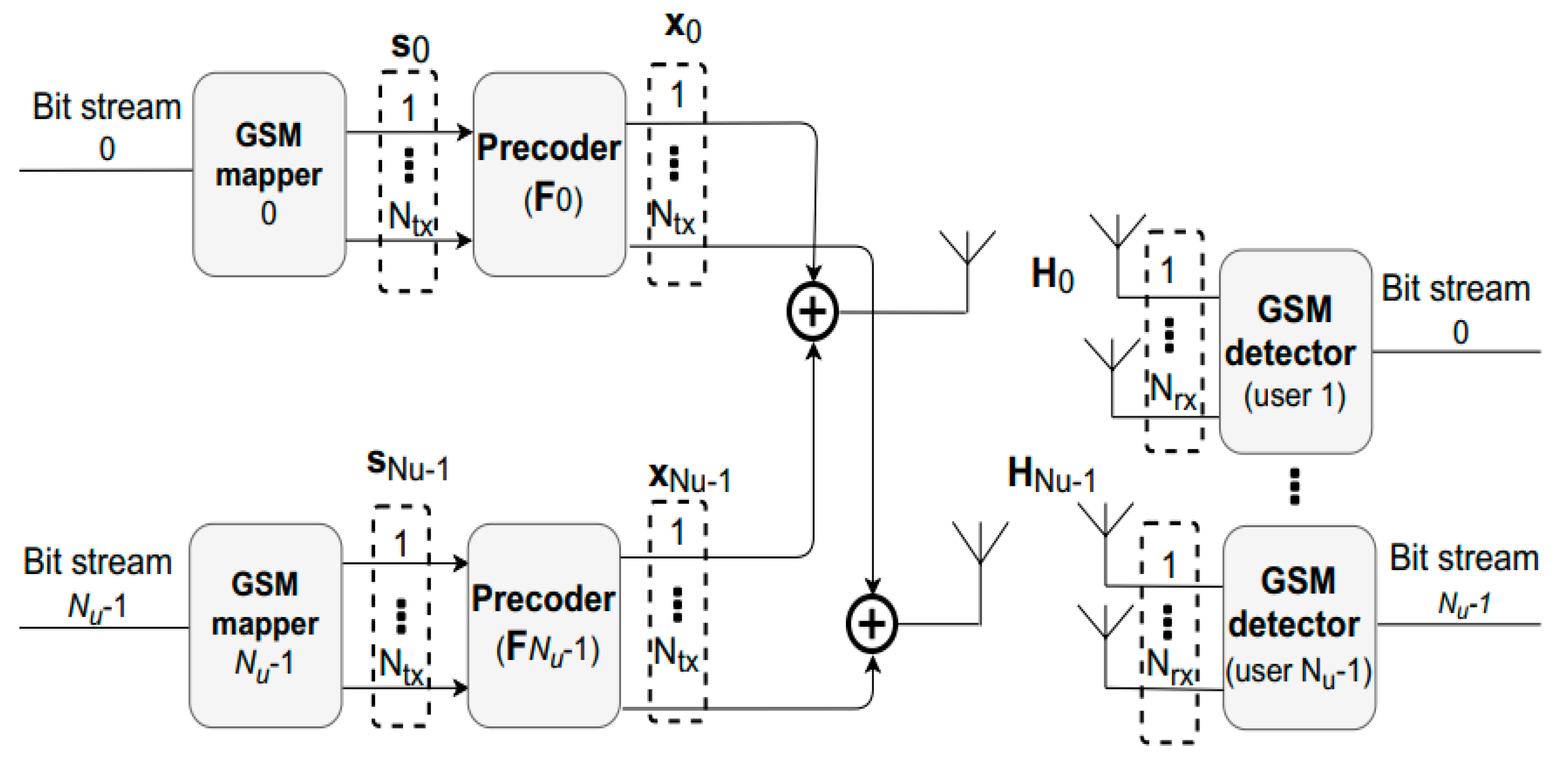
Let us consider a downlink MU-MIMO system where a BS transmits simultaneously to N u users. The BS is equipped with N t x antennas and each user has N r x antennas, as illustrated in Figure 1. We assume that the signal can be represented as s = [ s 0 T , , s N u 1 T ] T , where s k N s × 1 contains the information transmitted to user k and N s N t x / N u .
Considering that GSM is being used, only N a positions of s k are nonzero. These correspond to active indexes, which carry M-QAM modulated symbols. The signal vector of each user can be written as
s k = [ , 0 , s k 0 , 0 , , 0 , s k N a 1 , 0 , ] T
where s k j A ( j = 0 , , N a 1 ) with A denoting an M-QAM complex valued constellation set. According to this model, the information will be divided in such a way that part of the data are used to select an active index (AI) from a total N c o n b = 2 log 2 ( N a N s ) AI combinations (AICs) available per user. The remaining data are mapped onto N a complex-valued M-QAM symbols. The resulting SE is then
N b i t s = N u log 2 ( N a N s ) + N u N a log 2 ( M )
bits per channel use (bpcu).

3. Transmitter and Receiver Structure

In this section the transmitter and receiver structures’ design will be addressed. The receiver design will be based on the alternating direction method of the multipliers (ADMM), which will be explained further in Section 3.2.

3.1. Transmitter Design

Channel state information at the transmitter (CSIT) will be used to pre-process the symbols through a linear precoder F = [ F 0 , , F N u 1 ] , where F k N t x × N s . Considering that the transmitted signal propagates through a flat fading channel, the baseband signal received by user k can be written as
y k = H k x k + H k j = 0 j k N u 1 x j + n k .
where
x = k = 0 N u 1 x k = k = 0 N u 1 F k s k .
In this expression, H k N r x × N t x corresponds to the channel matrix for the link between the BS and user k and n k N r x × 1 is the noise vector with samples taken according to a zero-mean circularly symmetric Gaussian distribution with covariance 2 σ 2 I N r x . The first term in (4) is related to the desired signal and the second one is the interference caused by the other users’ signals. Moreover, the multiuser interference can be eliminated by using a BD method as proposed in [9]. Following this approach, the equivalent overall channel matrix HF, with H = [ H 0 T , , H N u 1 T ] T , will become block diagonal. A simple BD precoder without any power loading optimization is assumed in this paper, with each precoder matrix F k designed so as to enforce that H i F k = 0 for all i k . This particular condition can be satisfied using vectors selected from the null space of matrix H ˜ k , which is defined as
H ˜ k = [ H 0 T , , H k 1 T , H k + 1 T , , H N u 1 T ] T .
H ˜ k corresponds to the concatenation of the channel matrices between the BS and all users except user k. An orthonormal basis for the null space of H ˜ k can be found by computing its singular value decomposition (SVD) as
H ˜ k = U ˜ k Λ ˜ k [ V ˜ k ( 1 ) V ˜ k ( 0 ) ] H ,
where U ˜ k is the matrix with the left-singular vectors and Λ ˜ k is a rectangular diagonal matrix containing the nonzero singular values. V ˜ k ( 1 ) and V ˜ k ( 0 ) contain the right singular vectors corresponding to the nonzero singular values and the null singular values, respectively. F k is obtained from V ˜ k ( 0 ) by selecting its first N s columns. In this case, the signal arriving at each receiver reduces to
y k = H ^ k s k + n k ,
where H ^ k = H k F k is the equivalent single user channel seen by the receiver.

3.2. Receiver Design

Considering the system model and the BD precoder described in the previous sections, each receiver will have to apply simple single user GSM detection. This can be seen as an attempt to solve the MLD problem related to receiver k, which is formulated as
min s f ( s k ) y k H ^ k s k 2 2
subject   to   s k A 0 N s
supp ( s k ) S ,
where A 0 = d e f A { 0 } and S denotes the set of valid AICs, which has a size of N c o m b . Solving this non-convex problem directly would require excessive or even unfeasible computational complexity for moderate to large problem settings. To tackle the problem, we adopt instead a similar approach to the one we applied in [7], which is based on the idea of using ADMM as an heuristic for splitting a complex problem into a sequence of simpler ones (as addressed in [32]). Being an heuristic based approach, there will be no guarantee that the resulting algorithm will converge to the solution of the original MLD problem. While this means that the detector will be suboptimal, it will require a much lower computational cost. Following a similar derivation to the one provided in [7], we can arrive at the iterative detection algorithm shown in Table 2 which can be used in each GSM receiver.
In this table, u , w N t x / N u × 1 are scaled dual variables and ρ x and ρ z are penalty parameters associated to constraints (9) and (10). A careful tuning of these parameters will ensure that the algorithm reaches a good performance during its execution. In the algorithm, Q is the maximum number of iterations, D ( . ) denotes the projection onto set D = { s : supp ( s ) S } , and A 0 N s ( . ) is the projection over A 0 N s . The projection over set D can be accomplished by keeping the N a largest magnitude elements whose indices also match a valid antenna combination, whereas A 0 N s ( . ) can be computed as simple rounding of each component to the closest element in A 0 .
Although heuristic-based approaches as the one adopted in the proposed GSM detector can reach a solution faster, it may not be the optimal one. Therefore, it is not guaranteed that the algorithm will converge to the optimal solution of the original MLD problem (which is nonconvex). To increase the chances of finding an optimal solution and to improve the performance of the GSM detector, we present several different strategies. The first method is the simplest and consists of restarting the algorithm multiple times by using different initializations [32] for the variables u 0 , w 0 , x u ( 0 ) , z 0 required by the algorithm. Another improvement strategy that we propose relies on checking at the end of the algorithm if any of the P neighboring candidates result in an improvement of f ( s ^ c a n d i d a t e ) . These P neighbors can be selected amongst those with the closest supports using the algorithm presented in Table 3. A last possible refinement method that we consider consists of re-solving the MLD problem with the support set fixed according to the candidate point s ^ k generated by the main algorithm.
In this case, the resulting formulation becomes a conventional MIMO detection problem which can also be approximated by a simple projected MMSE estimate, i.e., as
s ^ I c a n d i d a t e = A N a ( ( H ^ k , I H H ^ k , I + 2 σ 2 I N a ) 1 H ^ k , I y k ) .
We refer to this third approach as the MMSE polishing step. In terms of computational complexity, the BD precoding requires the computation of N u SVDs, which is the step with the heaviest cost resulting in a complexity order of O ( N u 4 N r x 3 + N u 2 N t x 2 N r x ) . This cost is supported by the BS which typically can have higher computational capabilities. More critical is the required computational complexity at the users. Regarding the receiver, the s-update step (line 5 of Table 2) has the highest cost as it involves an N t x / N u × N t x / N u matrix inversion (although it is only computed in the beginning of the algorithm). Considering a fixed number of iterations, the total complexity order is O ( ( N t x / N u ) 3 ) . For comparison, the complexity order of MLD is O ( N c o m b M N a ) (with N c o m b = 2 log 2 ( N s N a ) ), of a linear MMSE is O ( ( N t x / N u ) 3 ) , of OB-MMSE [33] is O ( N c o m b N a 3 ) and of multipath matching pursuit with slicing (sMMP) [34] is O ( N t x N u N r x ( 1 T K ) / ( 1 T ) + ( N a 2 N r x + N a 3 ) T K ) (T is the number of child candidates expanded at each iteration). Therefore, the proposed approach has a similar complexity order to the linear MMSE. Note that the complexity of OB-MMSE does not grow exponentially with the signal constellation size, M, like in the case of MLD, but it still depends on N c o m b = 2 log 2 ( N s N a ) which can restrict its use when a large number of bits are conveyed on antenna indices.

4. Numerical Results

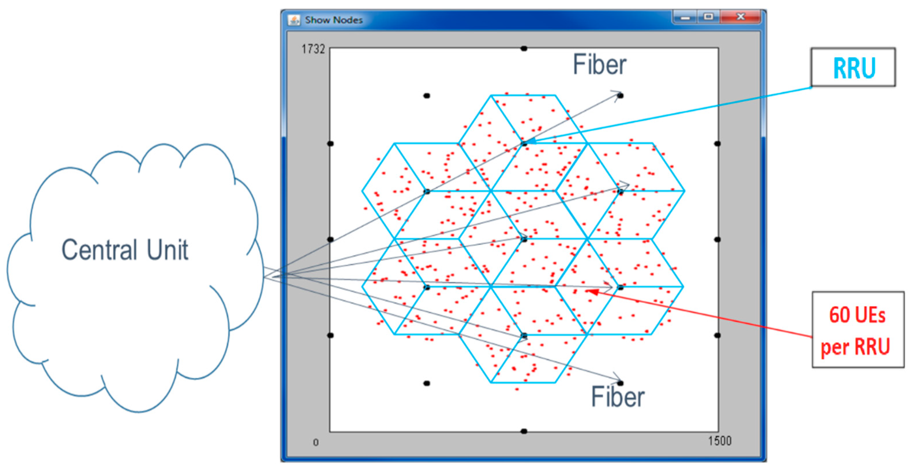
In this section, we present numerical simulations, both link level and system level. Link performance results, namely, block error rate (BLER), are used as input by the system level simulator. The system is illustrated in Figure 2, where the C-RAN is comprised of 19 radio remote units (RRUs) connected through fiber to a central unit (CU), each RRU with N = 60 active pedestrian users. Each RRU consists of three transmission and reception points (TRP), each one equipped with N t x t o t a l = 256 antennas while users have N r x antennas (i.e., each RRU corresponds to a BS according to the system model presented in Section 2). The RRUs array configuration corresponds to cylindrical arrays: 16 × 16 × 3, where the separation between antennas of the array is half wavelength [35].
The system level block diagram can be found in references [36,37]. This simulator is based on the one described in [37]. In the system level simulator, there are general parameters that must be defined, such as network layout and antenna parameters. The setup used considers several of the same parameters adopted in the case study presented in Section 7.7 of [38] for the deployment of a Massive MIMO based outdoor network. Our system level simulator considers the 3D urban macro 3D-Uma scenario [36], where the BSs are mounted above rooftop levels of surrounding buildings with antenna height: 25 m and pedestrians height: 1.5–2.5 m. To each pedestrian is assigned line-of-sight (LOS) or non-line-of-sight (NLOS) propagation conditions, depending on the distance to RRU. It is generated correlated large-scale and small-scale parameters to create channel coefficients and pathloss and shadowing are applied with σ S F = 7.8   dB . For the NLOS pathloss distance, we have P L = 32.4 + 20 log ( f c ) + 30 log ( d 3 D ) dB, where d 3 D is the distance in meters [36]. Other simulator parameters are: carrier frequency f c = 3.5   GHz , maximum TRP transmit power 46 dBm, receiver spectral noise power density −174 dBm/Hz, cyclic prefix overhead 5%, pilots/TRP = 15 and arrays with uni-polarized antennas. We choose the 5G NR numerology 1 and slot configuration parameters taken from [39]: the bandwidth is B t = 20   MHz with normal CP where the subcarrier spacing is 30 kHz and 28 OFDM symbols are transmitted in every subframe of 1ms. Each user feedbacks all CSI and signal-to-interference-plus-noise ratio (SINR) to TRPs. The static clustering technique partitions the network into three adjacent RRUs sets where each user is served by at least one RRU, while the others perform inter-user interference. The RRU inter-site distance is 433 m corresponding to a radius of 250 m.

4.1. Link Level Simulations

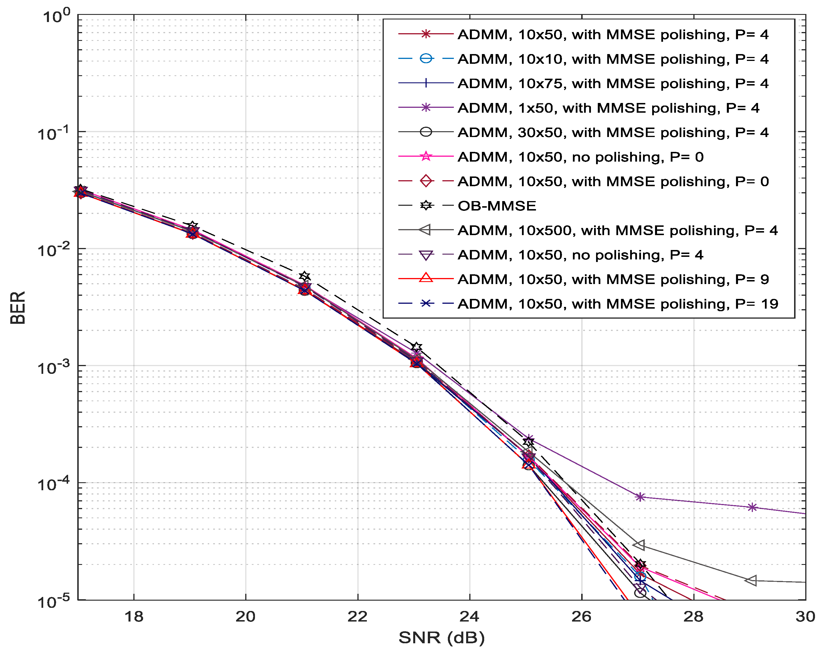
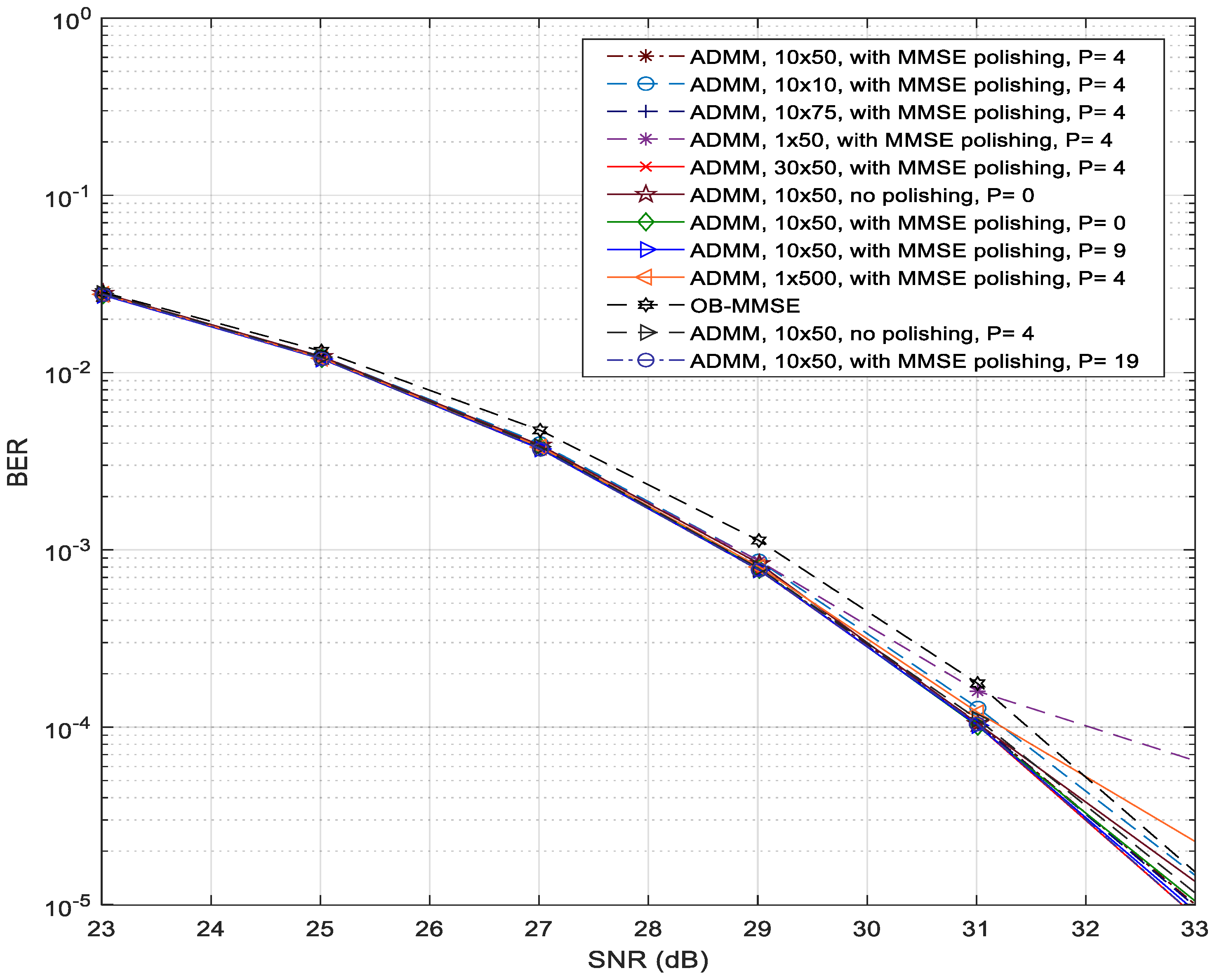
The first simulation results had the objective of evaluating the behavior of the iterative GSM receiver and of the overall proposed GSM MU-MIMO transmitter/receiver scheme. Figure 3 and Figure 4 present the results of BER performance versus the signal-to-noise ratio (SNR) in dB of the proposed GSM MU-MIMO system with N t x = 255 , N r x = 10 , N u = 15 , N s = 17 and N a = 2 , which corresponds to a spectral efficiency of 23 bpcu/user for 256-QAM and 27 bpcu/user for 1024-QAM.
The expression n 1 × n 2 , mentioned in the legend of both figures, denotes that the receiver algorithm was ran with n 1 restarts and n 2 iterations. The type of polishing applied as well as the number of neighbors is also shown. Besides the expected improvement when using more iterations, it can be observed that by increasing the number of algorithm restarts, we can achieve a better system performance. When considering the 1 × 500 and 10 × 50 cases, which have the same total number of iterations, it is clear that the best results are achieved by the case with more restarts (10 × 50). Considering the scenarios where MMSE polishing is used and those where it is not, one can observe that those where polishing is applied have better performance. We also studied the impact of changing the number of neighbors on the performance of the algorithm and we concluded that the greater the number of neighbors, the better the performance will be (see the cases where P = 1, 4, 9 and 19). Moreover, the combination of the three proposed improvement strategies for the ADMM receiver lead to a better performance than the usage of the individual approaches. Globally, the proposed ADMM algorithm tends to lead to better results when compared to the case where the well-known OB-MMSE receiver (which we included as benchmark) is used [6].
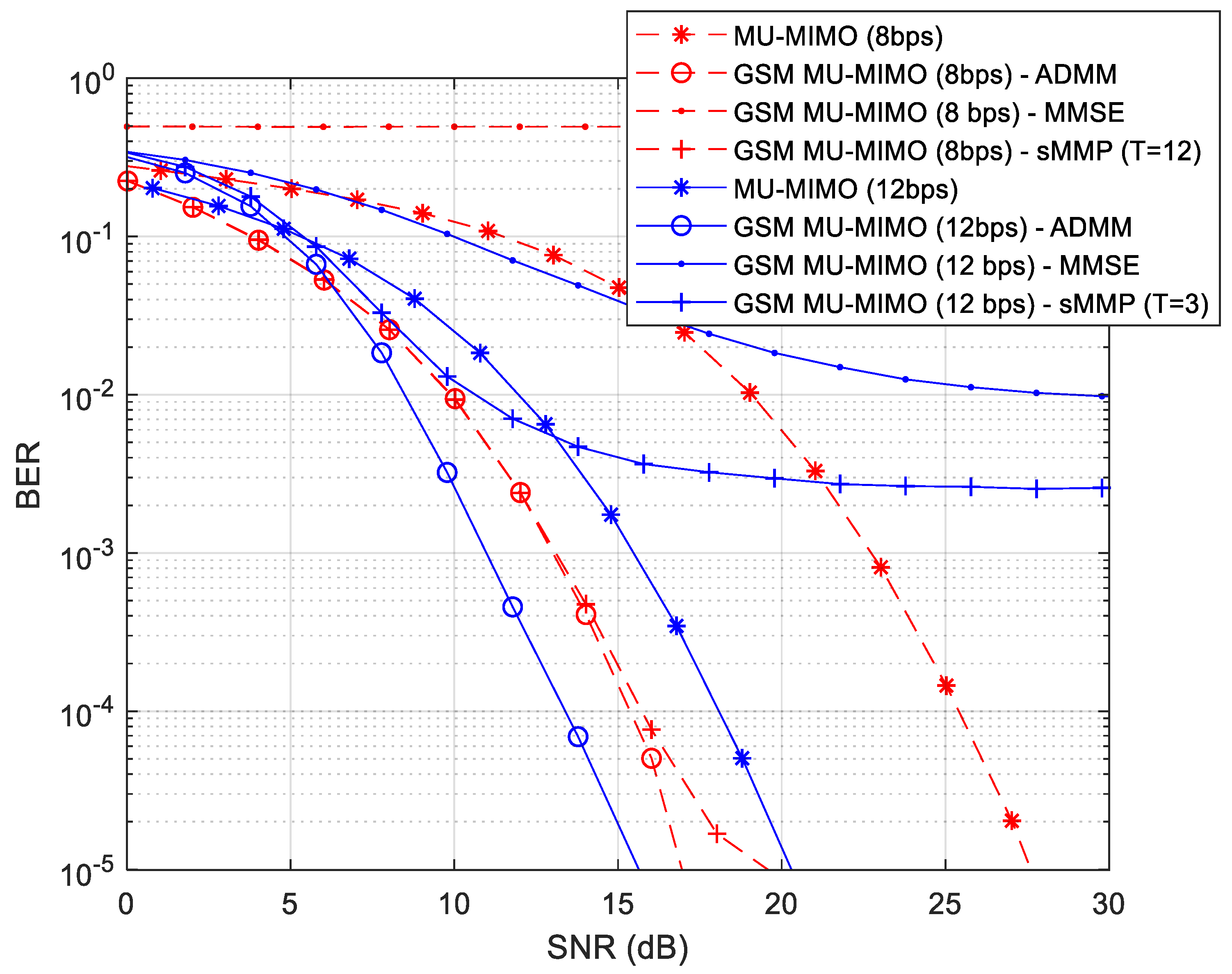
Our next goal is to provide a comparison between a conventional BD precoded MU-MIMO [9] and the proposed GSM MU-MIMO. Figure 5 shows the results for two different configurations. The first case concerns a comparison between the precoded GSM MU-MIMO with N t x = 160 , N r x = 6 , N u = 10 , N s = 16 , N a = 1 , 16-QAM and the conventional BD precoded MU-MIMO with N t x = 60 , N r x = 6 , N u = 10 , N s = 1 and 256-QAM, both with a spectral efficiency of 8 bpcu/user. In the second case, we present a comparison between the precoder based on GSM MU-MIMO with N t x = 90 , N r x = 8 , N u = 10 , N s = 9 , N a = 3 , quadrature phase-shift keying (QPSK) and the precoder based on conventional MU-MIMO with N t x = 80 , N r x = 8 , N u = 10 , N s = 3 and 16-QAM, both with a spectral efficiency of 12 bpcu/user. Regarding the GSM MU-MIMO scheme, results with the proposed receiver as well as other alternative ones are included, namely with a linear MMSE and with the sMMP (from [34]). In the case of sMMP, a lower number of child nodes (T = 3) was adopted for 12 bpcu due to the very high computational complexity when operating with higher values in this scenario.
In the results, it is clear that the proposed ADMM receiver achieves the best results when compared against sMMP and MMSE. In the case of MMSE, it simply cannot correctly detect the information (8 bps) or it has a high irreducible BLER (12 bps). This is due to the fact that from a receiver point of view, both scenarios correspond to underdetermined systems ( N r x < N s ), which a simple MMSE has a high difficulty to cope with. Through this figure, it can also be seen that the GSM MU-MIMO precoder with the proposed ADMM receiver achieves a better performance when compared to the conventional MU-MIMO precoder (which also uses the same receiver). When we focus on the curve’s behavior for a 10 4 BER considering a 8 bpcu/user scenario, the GSM MU-MIMO shows a gain of about 10 dB over the conventional MU-MIMO. Moving on to the 12 bpcu/user scenario and maintaining the BER at 10 4 , the GSM MU-MIMO presents a gain of about 5 dB over the conventional MU-MIMO. These results suggest that GSM MU-MIMO can be a potential alternative to increase the SE of the system when compared with the adoption of higher-level modulations in conventional MU-MIMO.
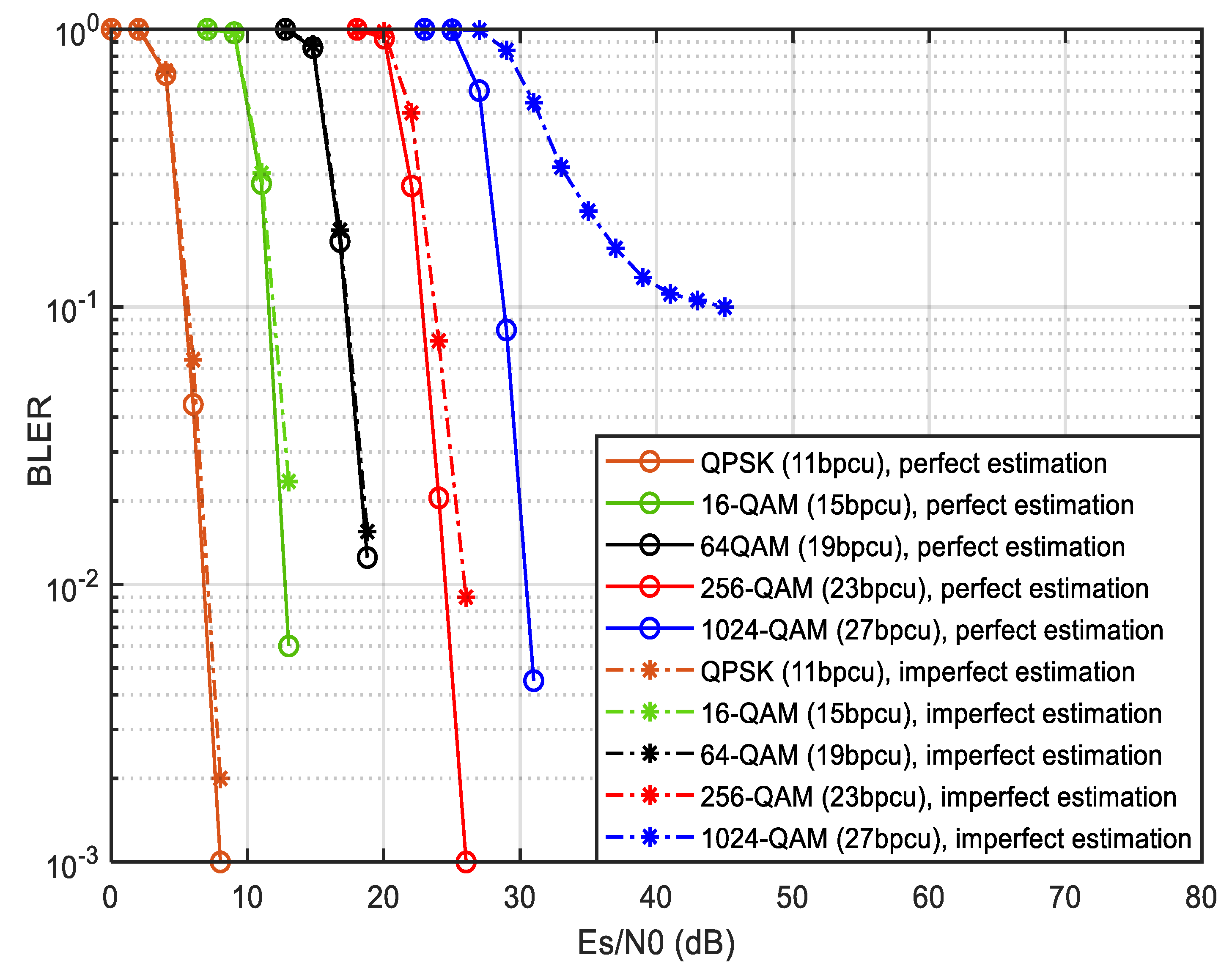
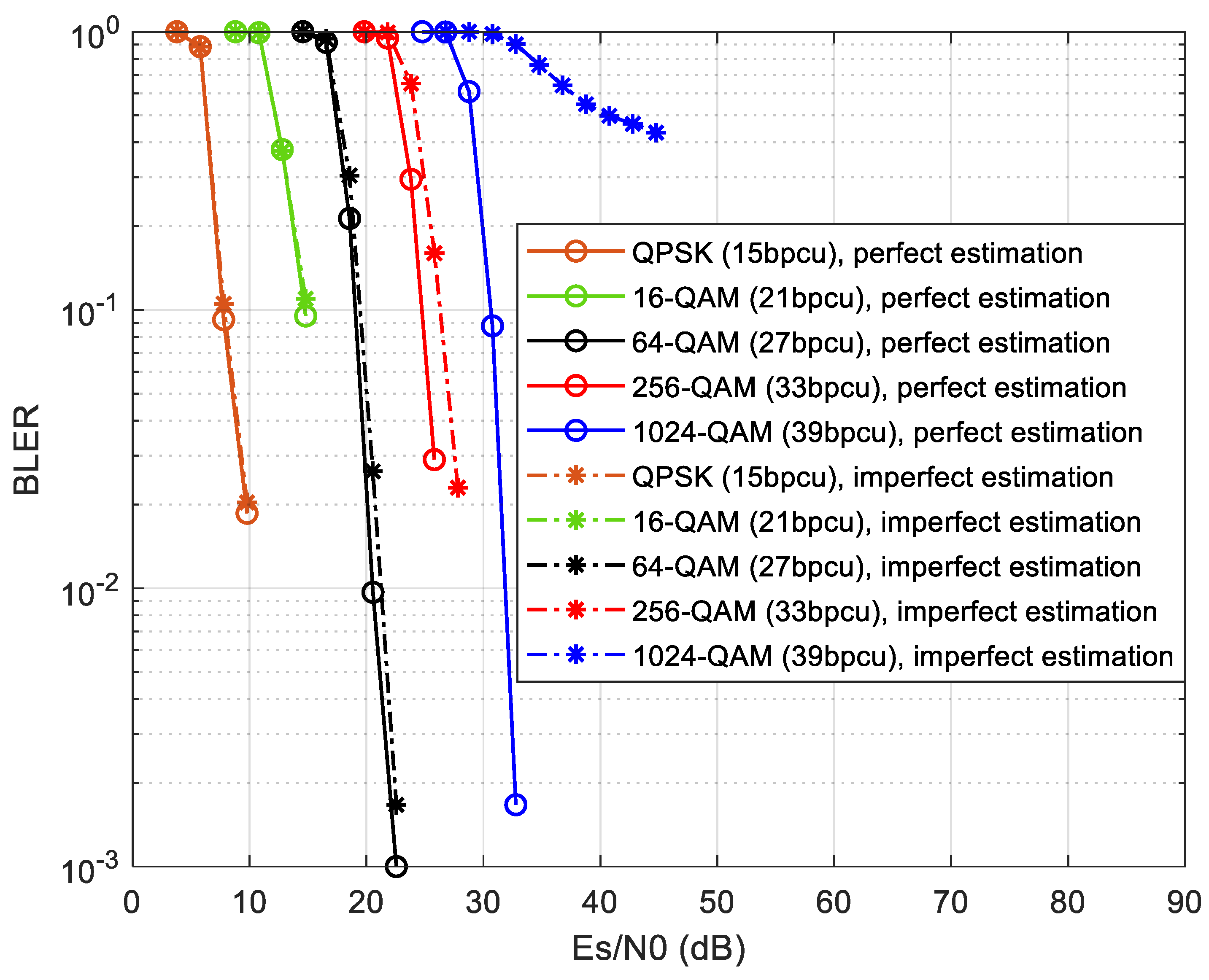
A second set of simulations were performed in order to analyze the block error rate (BLER) performance versus the energy per symbol to noise power spectral density ( E s / N 0 ) in dB of the proposed GSM MU-MIMO system. These results are required for the system level evaluation in the next subsection. Both perfect channel estimation and imperfect channel estimation curves are presented. For the imperfect channel estimation results we adopted the same model as in [40]. Denoting the CSI available at the transmitter as H ¯ and the CSI error as H e r r o r we can express the channel matrix as H = H ¯ + H e r r o r . The entries of H ¯ and H e r r o r are drawn assuming complex Gaussian distributions of C N ( 0 , σ h ¯ 2 ) and C N ( 0 , σ h e r r o r 2 ) , with σ h ¯ 2 + σ h e r r o r 2 = 1 . In the presented results we considered σ h e r r o r = 0.03 . In our simulations, a minimum of 25,000 blocks were transmitted for computing each BLER result. In Figure 6 and Figure 7, we have N s c = 256 subcarriers, N t x = 17 antennas/user, N r x = 16 antennas/user and N u = 15 users. The number of active antennas are N a = 2 and N a = 3 , respectively. The case N a = 3 and 1024-QAM corresponds to a spectral efficiency of 39 bpcu/user. The peak bit rate per user achieved assuming 5G NR numerology 1 is 279.552 Mbps. This means that 1 bpcu/user is equivalent to bit rate of 7.168 Mbps.
Doubling N s c = 256 to N s c = 512 doubles the spectral efficiency to 78 bpcu/user use which is equivalent to a bit rate of 14.336 Mbps. In both figures, the BLER of GSM MU-MIMO is presented versus ( E s / N 0 ) in dB, for five uniform M-QAM constellations namely, M ∈ {4,16,64,256,1024}. As expected, independently of N a , higher values of M require higher values of E s / N 0 (dB) to reach the reference BLER = 10 1 . In Figure 6, 1024-QAM with perfect estimation requires an additional 24 dB of E s / N 0 compared to 4-QAM(QPSK). With imperfect channel estimation there is an additional 15 dB penalty to reach BLER = 10 1 in the detection of 1024-QAM (it has a higher sensitivity to channel estimation errors).
In Figure 7, for N a = 3 , it is clear the higher sensitivity of 1024-QAM, as one can notice that with imperfect estimation there is the emergence of a BLER floor. The other modulations only reveal small or negligible degradation.

4.2. System Level Simulations

Using the BLER results described previously, several system level simulations were performed. The signal-to-noise ratio in dB used in the system level simulations is obtained using S N R = ( E s / N 0 ) + 10 log ( R s / B ) dB, where R s is the total transmitted symbol rate per antenna and user, B is the total bandwidth (we considered 20MHz), and E s / N 0 is the ratio of symbol energy to noise spectral density in dB. Values of E s / N 0 are obtained from the link level BLER results.
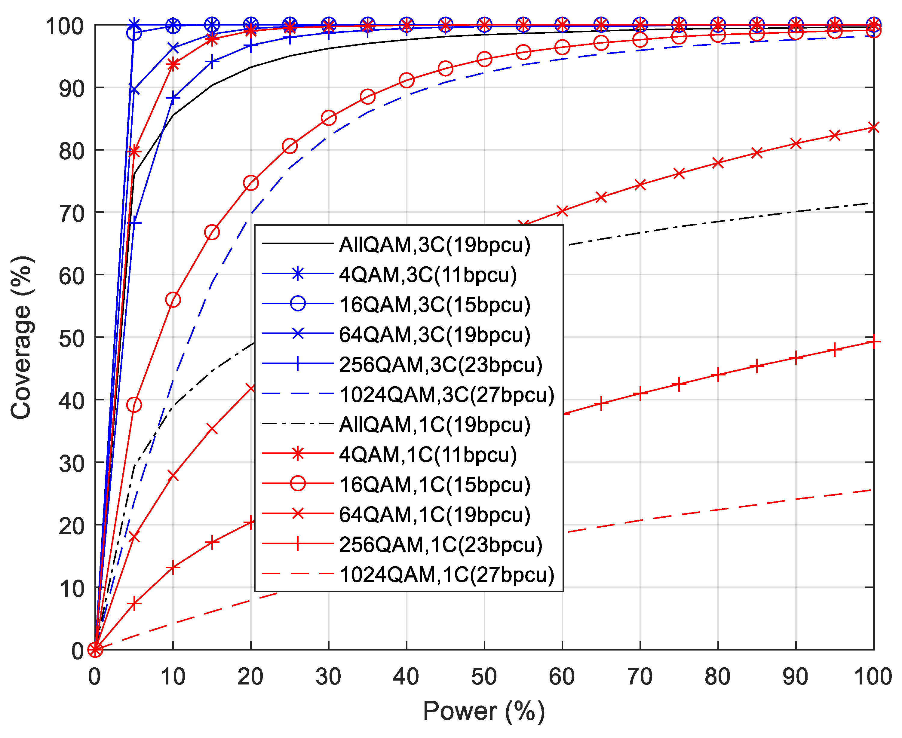
In Figure 8, we have chosen N a = 2 with perfect estimation, and computed the SNR values corresponding to the BLER = 10 1 so as to obtain the coverage results vs. the percentage of transmitted carrier power. Based on the parameters N u = 15 , N t x = 17 transmit antennas/user and N r x = 16 receive antennas/user there are a total of 255 active antennas at each TRP. The coverage of each of the five different M-QAM constellations and the arithmetic average of the coverage of all constellations (labelled as AllQAM) is presented for two different clusterings. In the present cellular topology, RRUs correspond to base stations, and each user is served by one RRU while the other RRUs generate inter-interference when transmitting towards their users. The label 1C means that the cluster contains one RRU. According to BLER performance results of Figure 6, it is expected that the 1024-QAM constellation has the minimum coverage due to more demanding signal-to-noise ratio, while 4-QAM has the maximum coverage for 100% of the transmitted carrier power. Only users close to RRUs are able to decode correctly 1024-QAM symbols, whereas 4-QAM symbols are decoded everywhere. We can check in Figure 8 that only for 100% of transmitted carrier power, the average coverage of all constellations reaches 71.5% of the area. The remaining coverage curves correspond to clustering where the network is partitioned into three adjacent RRU sets and each user is served by three RRUs (labelled as 3C). It is clear that there is an improved coverage obtained for all constellations, which is due to a much lower inter-interference between RRUs. Now, the average coverage of all constellations for 100% of carrier power is 99.6%, which corresponds to a coverage gain of 139%.
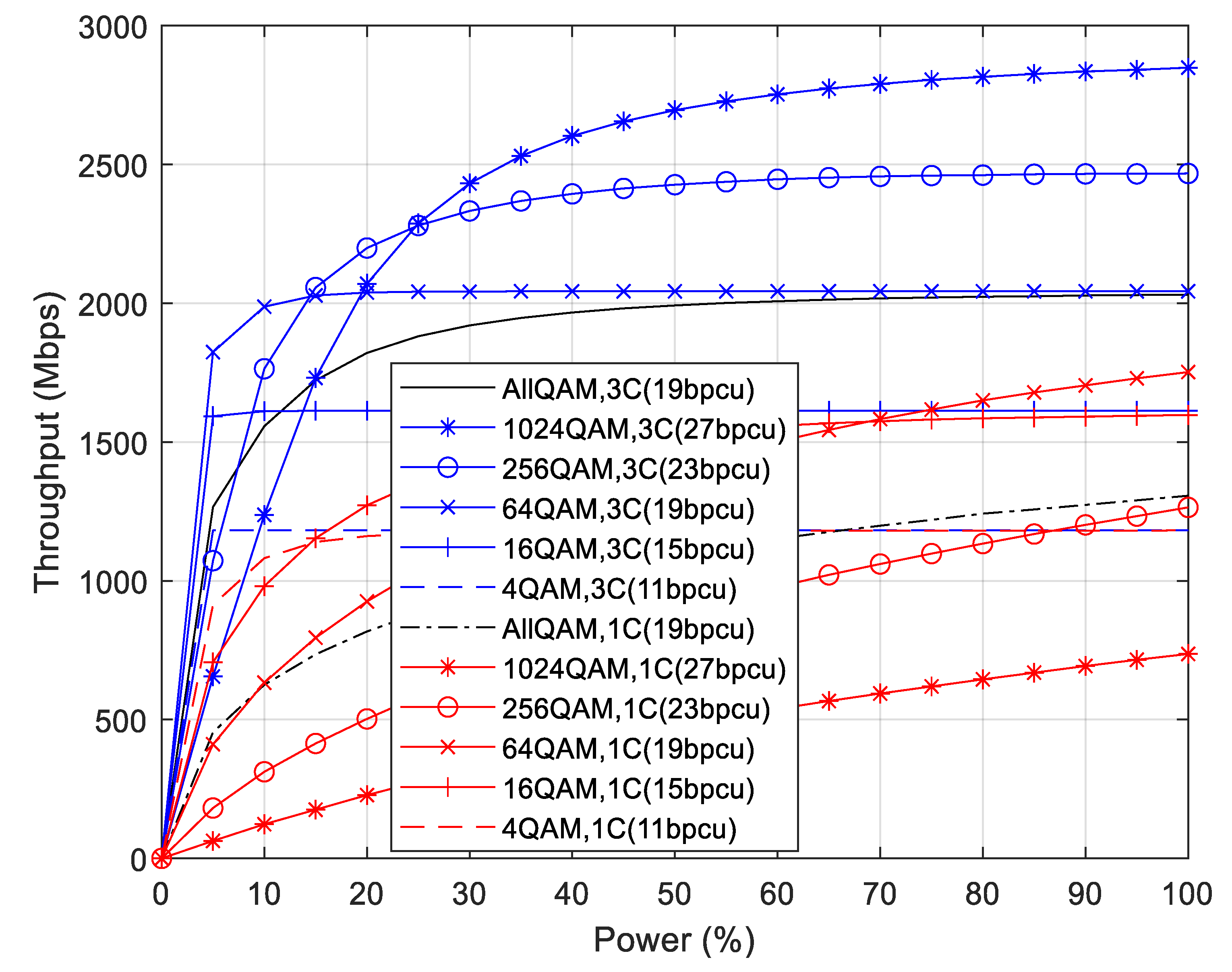
In Figure 9, the average throughput results corresponding to the coverage results of the previous figure are presented. Considering the impact of clustering in which only one RRU (1C) is transmitting, the constellation with the lowest throughput is 1024-QAM and the highest result is achieved for 64-QAM. The latter presents a better tradeoff of coverage and spectral efficiency when compared to the use of 16-QAM and 4-QAM constellations. For 15 users and 100% of transmitted carrier power, the average throughput obtained with all constellations is 1306.5 Mbps (87.1 Mbps/user). For the clustering where three RRUs (3C) transmit to each user, the constellation with the highest throughput is 1024-QAM, followed by 256-QAM, 64-QAM, 16-QAM, and 4-QAM. There is a match between the spectral efficiency (bpcu) of each constellation and the corresponding average throughput achieved at C-RAN system level. In fact, the same type of match is also observed for the curve of all constellations with spectral efficiency of 19 bpcu and the average throughput achieved at RAN. Notice that the spectral efficiency of 19 bpcu corresponds to a 64-QAM constellation and is equal to the average spectral efficiency of all constellations. For 15 users and 100% of transmitted power, the average throughput of all constellations is 2031.0 Mbps (135.4 Mbps/user), which gives a throughput gain of 155%.
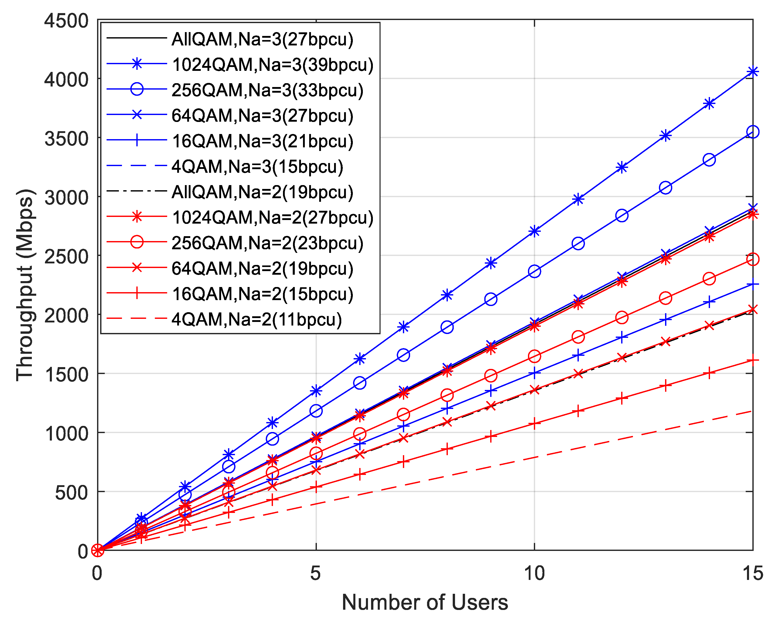
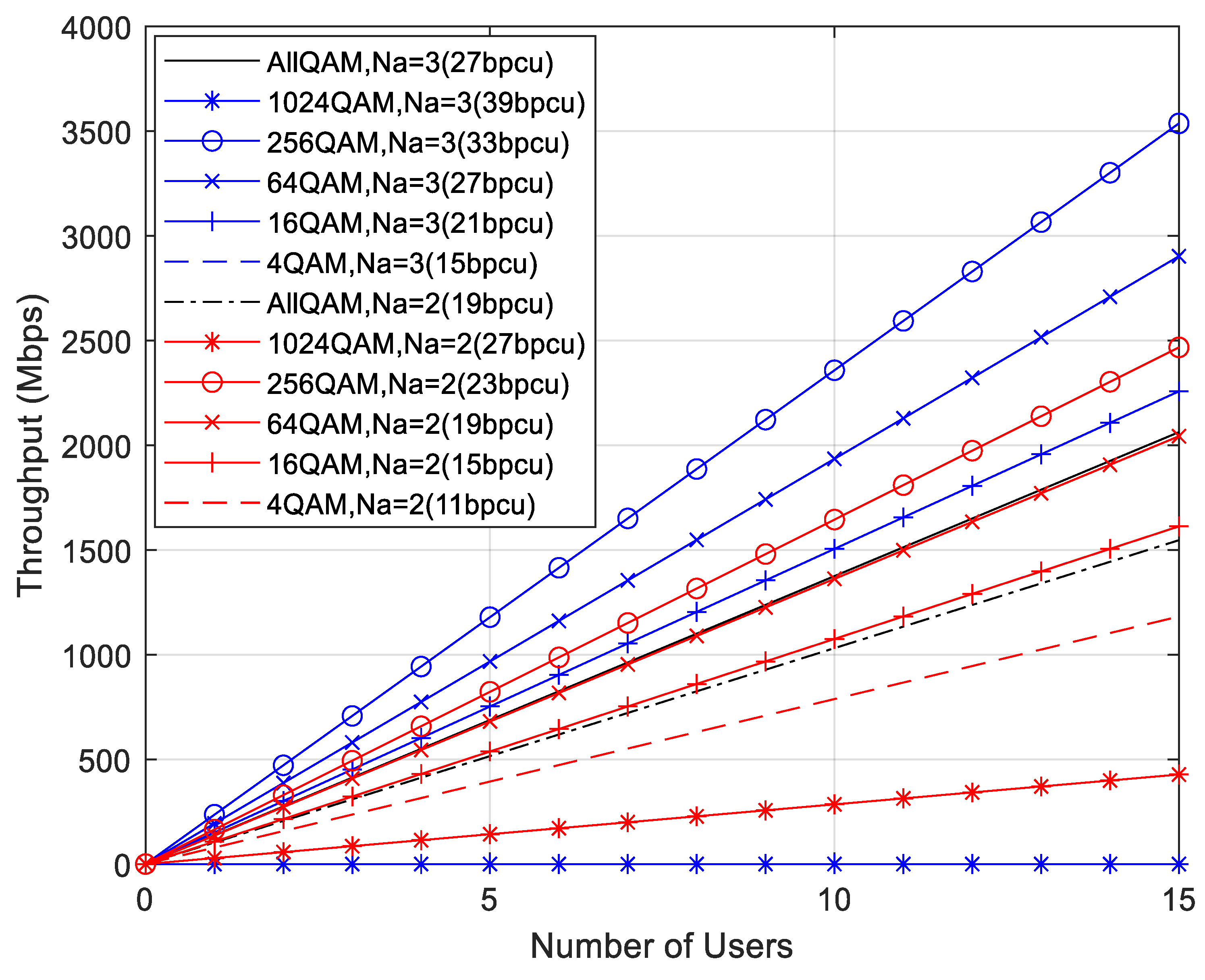
Figure 10 presents the throughput averaged over all users uniformly distributed, for the C-RAN scenario where three RRUs (3C) transmit to each user. The parameters of the previous figures are kept the same, namely N t x = 17 antennas/user, N r x = 16 antennas/user, N s c = 256 , and we vary the number of users N u from 1 up to 15, considering 100% of transmitted carrier power. We consider that the channel estimation is perfect. We can confirm that the BD MU precoding used at the RRUs and the ADMM receivers are operating as expected because every throughput curve is a straight line with slope dependent of the constellation but independent of N u . The increase in throughput depends on the spectral efficiency. We present two set of results. For N a = 2 , the minimum is 11 bpcu (4-QAM) and the maximum is 27 bpcu (1024-QAM). The second set of performance curves have N a = 3 , starting from 15 bpcu (4-QAM) up to a maximum of 39 bpcu (1024-QAM). We observe the same throughput results for 15 bpcu with 16-QAM and N a = 2 or 4-QAM with N a = 3 . The throughput results are almost the same between the average of all constellations with N a = 2 (19 bpcu) or N a = 3 (27 bpcu) and the 64-QAM constellation having the same spectral efficiencies. This can be explained because the average coverage of all constellations is only slightly lower than the coverage of 64-QAM. The ratio of throughput results for the average of all constellations with N a = 3 (27 bpcu) compared to those of N a = 2 (19 bpcu) is 2875.8/2031.0 = 1.42, the same as the expected ratio (27 bpcu/19 bpcu) = 1.42.
Figure 11 considers the same parameters of Figure 10 but the channel estimation is imperfect instead of perfect. Some performance degradation due to imperfect channel estimation can be observed. The throughput results are not anymore the same between the average of all constellations with N a = 2 (19 bpcu) or N a = 3 (27 bpcu) and the 64-QAM constellation having the same spectral efficiencies. Indeed, the simulation results indicate that the throughput of the average of all constellations is lower than the 16-QAM constellation results with N a = 2 (15 bpcu) or N a = 3 (21 bpcu). For both numbers of active antennas, the throughput results for 1024-QAM become the lowest instead of the highest and for N a = 3 , the throughput is zero (does not attain a BLER of 10−1 as observed previously). There is an obvious decrease in the simulated throughput results compared to the expected results based on the constellation bpcu. The ratio of throughput results for the average of all constellations with N a = 3 (27 bpcu) compared to those of N a = 2 (19 bpcu) is 2062.5/1546.5 = 1.33, lower than the expected ratio (27 bpcu/19 bpcu) = 1.42. The comparison between Figure 10 and Figure 11 indicates that the throughput reduction due to imperfect channel estimation for N a = 2 is (1-1546.5/2031.0) = 0.24 and for N a = 3 is (1-2062.5/2875.8) = 0.28. Therefore, the throughput reduction due to imperfect estimation increases with the number of GSM active antennas which was expected based on the BLER results of Figure 6 and Figure 7.
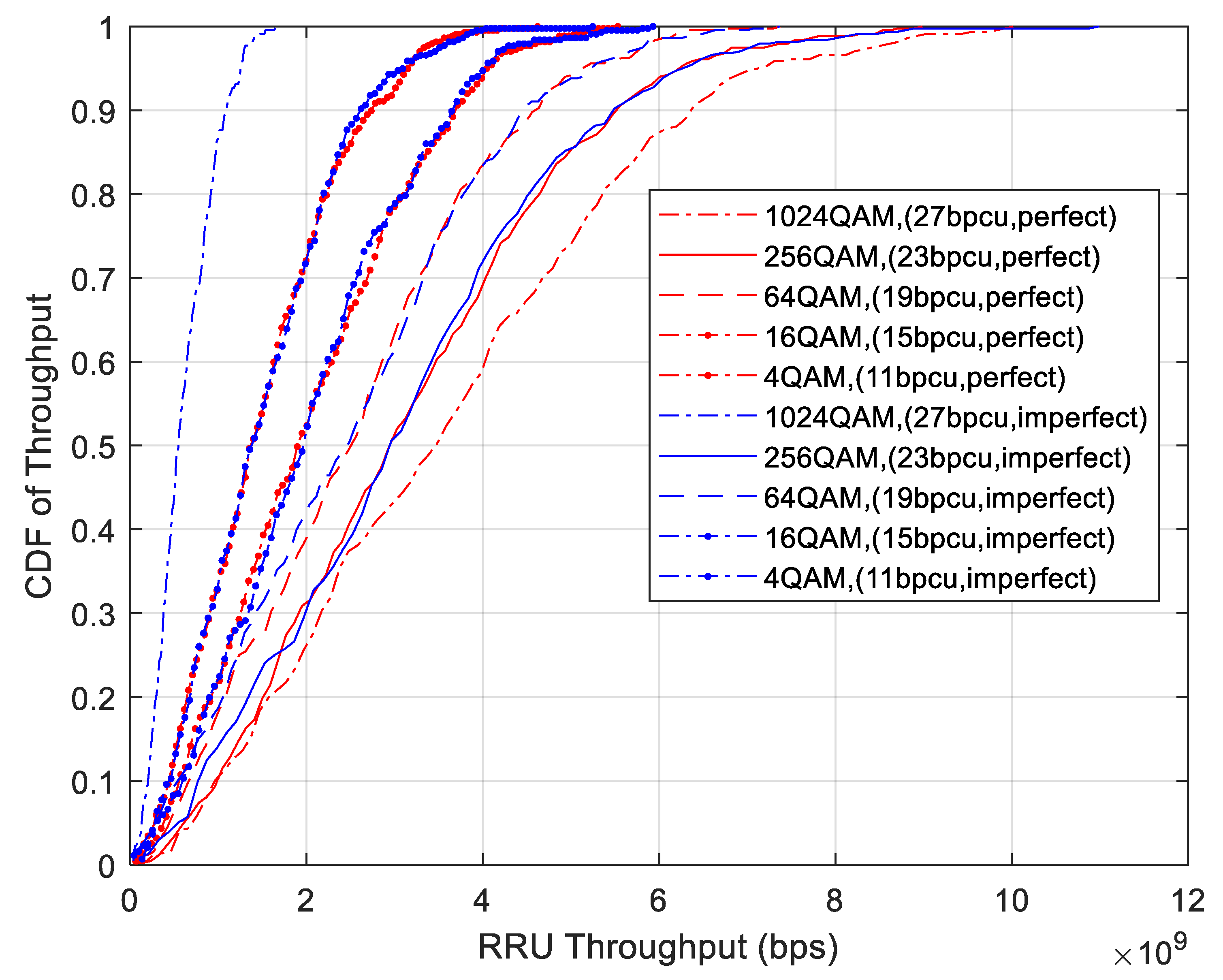
Figure 12 presents the cumulative distribution function (CDF) of a RRU with three TRPs, each TRP with N t x = 255 active antennas serving 60 users each with N r x = 16 antennas. The CDF of this figure corresponds to the case of 100% of carrier transmission power. We consider only the C-RAN scenario with clusters of three RRUs (3C), with curves for both perfect channel estimation and imperfect channel estimation cases. As expected, only for 1024-QAM there is an obvious difference in CDF results due to imperfect estimation compared to perfect estimation. For the other constellations, there are almost the same CDF results which is in agreement with the BLER results of Figure 6. The receiving throughput of all users exceeds 2.5 Gbps, 3.5 Gbps, 4.5 Gbps, 5.5 Gbps, and 6.5 Gbps for 10% of the users with 4-QAM, 16-QAM, 64-QAM, 256-QAM, and 1024-QAM (perfect estimation), respectively. For 50% of the users, the throughput received corresponds to the performance results presented on Figure 9. Only less than 10% of users receive a throughput level lower than 100 Mbps, with the exception of 1024-QAM users with imperfect estimation.
Table 4 summarizes the average throughput per user with perfect and imperfect channel estimation for C-RAN with clusters 1C and 3C and the corresponding throughput gain. The maximum throughput gain is 1.55 and the minimum is 1.25.
5. Conclusions

In this paper, a novel MIMO system where GSM symbols are transmitted simultaneously to multiple users has been described. By combining large antenna settings at the BS with high-order M-QAM constellations, the proposed approach is capable of improving the spectral efficiency and energy efficiency. A precoder is applied at the BS to completely remove inter-user interference, while a reduced complexity iterative SU GSM detector is implemented at each receiver. Simulation results show that the proposed approach can achieve a very competitive and very promising performance compared to conventional MU-MIMO systems with identical SE. In fact, system level results based on a C-RAN scenario with multiple RRU showed potential gains of up to 155% in throughput and 139% in coverage when compared to traditional cellular networks. The introduction of imperfect channel estimation reduces the throughput gain to 125%. Future work will include a thorough evaluation of the impact of several hardware impairments (such as phase-noise, non-linear distortion, and I/Q imbalances) and robust mitigation algorithms.

Author Contributions

Conceptualization, J.P.P., A.C., B.B. and N.S.; methodology, J.P.P., A.C., B.B. and N.S.; software, J.P.P., A.C., V.V., B.B. and N.S.; validation, J.P.P., A.C., B.B., V.V. and N.S.; formal analysis, J.P.P., A.C., B.B., V.V. and N.S.; investigation, J.P.P., A.C., B.B., V.V. and N.S.; resources, A.C. and N.S.; data curation, J.P.P., B.B., V.V., N.S. and A.C.; writing—original draft preparation, J.P.P., A.C., B.B. and N.S.; writing—review and editing, J.P.P., A.C., B.B., V.V. and N.S.; visualization, J.P.P., A.C., B.B., V.V. and N.S.; supervision, A.C. and N.S.; project administration, A.C. and N.S.; funding acquisition, A.C. and N.S. All authors have read and agreed to the published version of the manuscript.

Funding

This research was partially funded by the ISCTE-University Institute of Lisbon under the grant ISTA-BMPDCTI-2019 and by the FCT/MCTES through national funds and when applicable co-funded by EU funds under the project UIDB/50008/2020.

Acknowledgments

The authors acknowledge the support of ISCTE—University Institute of Lisbon, Fundação para a Ciência e Tecnologia (FCT) and Instituto de Telecomunicações (IT), as described above in funding.

Conflicts of Interest

The funders had no role in the design of the study; in the collection, analyses, or interpretation of data; in the writing of the manuscript, or in the decision to publish the results.

References

  1. Yuan, W.; Wu, N.; Zhang, A.; Huang, X.; Li, Y.; Hanzo, L. Iterative Receiver Design for FTN Signaling Aided Sparse Code Multiple Access. IEEE Trans. Wirel. Commun. 2020, 19, 915–928. [Google Scholar] [CrossRef] [Green Version]
  2. Cheng, X.; Zhang, M.; Wen, M.; Yang, L. Index Modulation for 5G: Striving to Do More with Less. IEEE Trans. Wirel. Commun. 2018, 25, 126–132. [Google Scholar] [CrossRef] [Green Version]
  3. Correia, A.; Souto, N.; Sebastiao, P.; Gomez-Barquero, D.; Fuentes, M. Broadcasting Scalable Video with Generalized Spatial Modulation in Cellular Networks. IEEE Access 2020, 8, 22136–22144. [Google Scholar] [CrossRef]
  4. Datta, T.; Eshwaraiah, H.; Chockalingam, A. Generalized Space-and-Frequency Index Modulation. IEEE Trans. Veh. Technol. 2016, 65, 4911–4924. [Google Scholar] [CrossRef] [Green Version]
  5. Murtala, S.; Holoubi, T.; Muchena, N.; Mohaisen, M.; Choi, K. On the Performance of the Multiple Active Antenna Spatial Modulation with 3-Dimensional Constellation. Appl. Sci. 2020, 10, 3718. [Google Scholar] [CrossRef]
  6. Jiang, Y.; Xu, Y.; Xie, Y.; Hong, S.; Wu, X. Low-Complexity Detection Scheme for Generalized Spatial Modulation. J. Commun. 2016, 11, 726–732. [Google Scholar] [CrossRef]
  7. Lopes, H.; Souto, N. Iterative Signal Detection for Large-Scale GSM-MIMO Systems. IEEE Trans. Veh. Technol. 2018, 67, 7734–7738. [Google Scholar] [CrossRef]
  8. Castaneda, E.; Silva, A.; Gameiro, A.; Kountouris, M. An Overview on Resource Allocation Techniques for Multi-User MIMO Systems. IEEE Commun. Surv. Tutor. 2017, 19, 239–284. [Google Scholar] [CrossRef] [Green Version]
  9. Zu, K.; de Lamare, R.; Haardt, M. Generalized Design of Low-Complexity Block Diagonalization Type Precoding Algorithms for Multiuser MIMO Systems. IEEE Trans. Commun. 2013, 61, 4232–4242. [Google Scholar] [CrossRef] [Green Version]
  10. Lopes, P.; Gerald, J. Leakage-based precoding algorithms for multiple streams per terminal MU-MIMO systems. Digit. Signal Process. 2018, 75, 38–44. [Google Scholar] [CrossRef]
  11. Guerreiro, J.; Dinis, R.; Montezuma, P.; Marques da Silva, M. On the Achievable Performance of Nonlinear MIMO Systems. IEEE Commun. Lett. 2019, 23, 1725–1729. [Google Scholar] [CrossRef]
  12. Chataut, R.; Akl, R. Massive MIMO Systems for 5G and beyond Networks—Overview, Recent Trends, Challenges, and Future Research Direction. Sensors 2020, 20, 2753. [Google Scholar] [CrossRef] [PubMed]
  13. Souto, N.; Correia, A. Frequency Domain Equalization for Single and Multiuser Generalized Spatial Modulation Systems in Time Dispersive Channels. IEEE Wirel. Commun. Lett. 2020, 9, 316–320. [Google Scholar] [CrossRef]
  14. Spencer, Q.; Swindlehurst, A.; Haardt, M. Zero-Forcing Methods for Downlink Spatial Multiplexing in Multiuser MIMO Channels. IEEE Trans. Signal Process. 2004, 52, 461–471. [Google Scholar] [CrossRef]
  15. Lee, W.; Ro, J.; You, Y.; Hwang, D.; Song, H. An Enhanced Precoder for Multi User Multiple-Input Multiple-Output Downlink Systems. Appl. Sci. 2020, 10, 4547. [Google Scholar] [CrossRef]
  16. Li, X.; Zhang, Y.; Xiao, L.; Xu, X.; Wang, J. A novel precoding scheme for downlink multi-user spatial modulation system. In Proceedings of the IEEE 24th Annual International Symposium on Personal, Indoor, and Mobile Radio Communications (PIMRC), London, UK, 8–11 September 2013; pp. 1361–1365. [Google Scholar]
  17. Zhang, H.; Ma, M.; Shao, Z. Multi-User Linear Precoding for Downlink Generalized Spatial Modulation Systems. IEEE Commun. Lett. 2020, 24, 212–216. [Google Scholar] [CrossRef]
  18. Marques da Silva, M.; Dinis, R.; Guerreiro, J. Energy-Efficient and Spectrally-Efficient MIMO. In Wiley 5G Ref: The Essential 5G Reference Online; Wiley Online Library: Hoboken, NJ, USA, 2019; pp. 1–18. [Google Scholar] [CrossRef]
  19. Marques da Silva, M.; Dinis, R.; Guerreiro, J. Implicit Pilots for an Efficient Channel Estimation in Simplified Massive MIMO Schemes with Precoding. Int. J. Antennas Propag. 2019, 2019, 1–11. [Google Scholar] [CrossRef]
  20. Gustavsson, U.; Sanchez-Perez, C.; Eriksson, T.; Athley, F.; Durisi, G.; Landin, P.; Hausmair, K.; Fager, C.; Svensson, L. On the impact of hardware impairments on massive MIMO. In Proceedings of the IEEE Globecom Workshops (GC Wkshps), Austin, TX, USA, 8–12 December 2014. [Google Scholar]
  21. Souto, N.; Dinis, R. Efficient MIMO Detection for High-Order QAM Constellations in Time Dispersive Channels. In Proceedings of the IEEE International Conference on Communications (ICC), Kansas City, MO, USA, 20–24 May 2018. [Google Scholar]
  22. Marques da Silva, M.; Dinis, R.; Guerreiro, J. A Low Complexity Channel Estimation and Detection for Massive MIMO Using SC-FDE. Telecom 2020, 1, 3–17. [Google Scholar] [CrossRef] [Green Version]
  23. Guerreiro, J.; Dinis, R.; Montezuma, P. Analytical Performance Evaluation of Precoding Techniques for Nonlinear Massive MIMO Systems with Channel Estimation Errors. IEEE Trans. Commun. 2018, 66, 1440–1451. [Google Scholar] [CrossRef] [Green Version]
  24. Mokhtari, Z.; Sabbaghian, M.; Dinis, R. A Survey on Massive MIMO Systems in Presence of Channel and Hardware Impairments. Sensors 2019, 19, 164. [Google Scholar] [CrossRef] [Green Version]
  25. Tullberg, H.; Popovski, P.; Li, Z.; Uusitalo, M.; Hoglund, A.; Bulakci, O.; Fallgren, M.; Monserrat, J. The METIS 5G System Concept: Meeting the 5G Requirements. IEEE Commun. Mag. 2016, 54, 132–139. [Google Scholar] [CrossRef]
  26. Cerwall, P. Ericsson Mobility Report. June 2019. Available online: https://www.ericsson.com/49d1d9/assets/local/mobility-report/documents/2019/ericsson-mobility-report-june-2019.pdf (accessed on 30 July 2020).
  27. 3rd Generation Partnership Project (3GPP). TR 36819 v11.2.0, Coordinated Multi-Point Operation for LTE Physical Layer Aspects, Release 11. September 2013. Available online: http://www.3gpp.org/ftp/Specs/archive/36_series/36.819/36819-b20.zip (accessed on 30 July 2020).
  28. Karakayali, M.; Foschini, G.; Valenzuela, R. Advances in smart antennas—Network coordination for spectrally efficient communications in cellular systems. IEEE Wirel. Commun. 2006, 13, 56–61. [Google Scholar] [CrossRef]
  29. Zhang, J.; Chen, R.; Andrews, J.; Ghosh, A.; Heath, R. Networked MIMO with clustered linear precoding. IEEE Trans. Wirel. Commun. 2009, 8, 1910–1921. [Google Scholar] [CrossRef] [Green Version]
  30. Dewa, G.; Park, C.; Sohn, I. Distributed Cell Clustering Based on Multi-Layer Message Passing for Downlink Joint Processing Coordinated Multipoint Transmission. Appl. Sci. 2020, 10, 5154. [Google Scholar] [CrossRef]
  31. Jabbar, S.; Li, Y. Analysis and Evaluation of Performance Gains and Tradeoffs for Massive MIMO Systems. Appl. Sci. 2016, 6, 268. [Google Scholar] [CrossRef] [Green Version]
  32. Boyd, S.; Parikh, N.; Chu, E. Distributed Optimization and Statistical Learning via the Alternating Direction Method of Multipliers. In Foundations and Trends in Machine Learning Series; Now Publishers Inc.: Delft, The Netherlands, 2010; pp. 1–122. [Google Scholar]
  33. Xiao, Y.; Yang, Z.; Dan, L.; Yang, P.; Yin, L.; Xiang, W. Low-Complexity Signal Detection for Generalized Spatial Modulation. IEEE Commun. Lett. 2014, 18, 403–406. [Google Scholar] [CrossRef]
  34. Shim, B.; Kwon, S.; Song, B. Sparse Detection with Integer Constraint Using Multipath Matching Pursuit. IEEE Commun. Lett. 2014, 18, 1851–1854. [Google Scholar] [CrossRef]
  35. Van Chien, T.; Björnson, E. Massive MIMO Communications. In 5G Mobile Communications; Xiang, W., Zheng, K., Shen, X., Eds.; Springer: Berlin, Germany, 2017. [Google Scholar] [CrossRef] [Green Version]
  36. 3rd Generation Partnership Project (3GPP). TR 38.901 v. 14.3.0. “5G: Study on Channel Model for Frequencies from 0.5 to 100 GHz”. Release 14. May 2017. Available online: http://www.3gpp.org/ftp/Specs/archive/38_series/38.901/38901-e11.zip (accessed on 9 September 2020).
  37. Correia, A.; Silva, M.M. Link and system level simulation for MIMO. In MIMO Processing for 4G and Beyond: Fundamentals and Evolution; Silva, M.M., Monteiro, F.A., Eds.; CRC Press: Boca Raton, FL, USA, 2014. [Google Scholar]
  38. Björnson, E.; Hoydis, J.; Sanguinetti, L. Massive MIMO Networks: Spectral, Energy and Hardware Efficiency. 2017. Available online: https://www.nowpublishers.com/article/Details/SIG-093 (accessed on 9 September 2020).
  39. 3rd Generation Partnership Project (3GPP). TS 38211 v15.2.0. 5G/NR Physical Channels and Modulation, Release 15. July 2018. Available online: http://www.3gpp.org/ftp/Specs/archive/38_series/38.221/38211-f20.zip (accessed on 30 July 2020).
  40. Stavridis, A.; Sinanovic, S.; Di Renzo, M.; Haas, H. Transmit precoding for receive spatial modulation using imperfect channel knowledge. In Proceedings of the IEEE 75th Vehicular Technology Conference (VTC Spring), Yokohama, Japan, 6–9 May 2012. [Google Scholar]
Figure 1. Transmitter and receiver scheme.
Applsci 10 06617 g001
Figure 2. Cloud radio access network (C-RAN) considered for the system level simulations. RRU = radio remote unit.
Applsci 10 06617 g002
Figure 3. Bit error rate (BER) performance of ADMM in a MU-MIMO scenario with N t x = 255, N r x = 10, N u = 15, N s = 17 and N a = 2, 256-QAM.
Applsci 10 06617 g003
Figure 4. BER performance of ADMM in a MU-MIMO scenario with N t x = 255, N r x = 10, N u = 15, N s = 17 and N a = 2, 1024-QAM.
Applsci 10 06617 g004
Figure 5. BER performance of a precoder based on GSM MU-MIMO and a precoder based on conventional MU-MIMO.
Applsci 10 06617 g005
Figure 6. Block error rate (BLER) vs. E s / N 0 for N a = 2 , N s c = 256 , N u = 15 , N t x = 17 antennas/user, and N r x = 16 antennas/user.
Applsci 10 06617 g006
Figure 7. Perfect and imperfect estimation of BLER vs. E s / N 0 for N a = 3 , N s c = 256 , N u = 15 , N t x = 17 antennas/user, and N r x = 16 antennas/user.
Applsci 10 06617 g007
Figure 8. Coverage vs percentage of transmitted power for N a = 2 , N s c = 256 , N u = 15 , N t x = 17 antennas/user and N r x = 16 antennas/user.
Applsci 10 06617 g008
Figure 9. Average throughput vs percentage of transmitted power for N a = 2 , N s c = 256 , N u = 15 , N t x = 17 antennas/user and N r x = 16 antennas/user.
Applsci 10 06617 g009
Figure 10. Average throughput vs number of users for N s c = 256 , N t x = 17 antennas/user and N r x = 16 antennas/user with perfect channel estimation.
Applsci 10 06617 g010
Figure 11. Average throughput vs number of users for N s c = 256 , N t x = 17 antennas/user, and N r x = 16 antennas/user with imperfect channel estimation.
Applsci 10 06617 g011
Figure 12. CDF of throughput for 100% transmitted power for N a = 2 , N s c = 256 , N u = 15 , N t x = 17 antennas/user, and N r x = 16 antennas/user.
Applsci 10 06617 g012
Table 1. Comparison between the reference conventional multi-user multiple input multiple output (MU-MIMO) and the proposed generalized spatial modulations multi-user multiple input multiple output (GSM MU-MIMO).
Conventional MU-MIMOGSM MU-MIMO
Precoder
  • Block Diagonalization
  • Block Diagonalization
Detector
  • conventional single user MIMO
  • proposed ADMM-based receiver
  • Single-user GSM detector capable of operating in undetermined scenarios (sMMP, OB-MMSE, …)
  • proposed ADMM-based receiver
Information Mapping
  • Modulated Symbols
  • Modulated Symbols
  • (Virtual) Antenna Indices
Possibilities for improving Spectral Efficiency
  • Increase modulation order
  • Increase number of transmit antennas → additional transmit power needed
  • Increase modulation order
  • Increase number of transmit antennas → no additional transmit power needed
Table 2. Iterative GSM detection algorithm for each user k.
1:Input: u 0 , w 0 , x 0 , z 0 , H ^ k , y k , ρ x , ρ z , Q
2: f b e s t = .
3: Φ ( H ^ k H H ^ k + ( ρ x + ρ z ) I N s ) 1 .
4:fort = 0, 1, …Q-1 do
5: s k ( t + 1 ) Φ ( H ^ k H y k + ρ x ( x ( t ) u ( t ) ) + ρ z ( z ( t ) w ( t ) ) ) .
6: x ( t + 1 ) D ( s k ( t + 1 ) ) .
7: z ( t + 1 ) A 0 N s ( s k ( t + 1 ) + w ( t ) ) .
8: I supp ( x ( t + 1 ) ) .
9: s ^ I ¯ c a n d i d a t e 0 , s ^ I c a n d i d a t e A N a ( s I ( t + 1 ) )
10:if f ( s ^ c a n d i d a t e ) < f b e s t then
11: s ^ k , I ¯ 0 , s ^ k , I s ^ I c a n d i d a t e .
12: f b e s t = f ( s ^ c a n d i d a t e ) .
13:end if
14: u ( t + 1 ) u ( t ) + s k ( t + 1 ) x ( t + 1 ) .
15: w ( t + 1 ) w ( t ) + s k ( t + 1 ) u ( t + 1 ) .
16:end for.
17:Output: s ^ k
Table 3. Solution refinement algorithm based on a closest neighbor search for user k.
1:Input: H ^ k , y k , s ^ , s k ( Q ) , f b e s t , P
2: D ¯ 0 = D , I supp ( s ^ )
3:forp = 1, …P do
4: D ¯ p = D ¯ p 1 \ { s : supp ( s ) = I } .
5: x D ¯ p ( s k ( Q ) )
6: I supp ( x ) .
7: s ^ I ¯ c a n d i d a t e 0 , s ^ I c a n d i d a t e A N a ( s I ( Q ) )
8:if f ( s ^ c a n d i d a t e ) < f b e s t then
9: s ^ k , I ¯ 0 , s ^ k , I s ^ I c a n d i d a t e .
10: f b e s t = f ( s ^ c a n d i d a t e ) .
11:end if
12:end for.
13:Output: s ^ k
Table 4. Average throughput per user with perfect and imperfect channel estimation and the corresponding throughput gain. CSI = channel status information.
NaCSI1C3CGain
2perfect87.1 Mbps135.4 Mbps1.55
2imperfect82.5 Mbps103.1 Mbps1.25
3perfect125.4 Mbps191.7 Mbps1.53
3imperfect103.4 Mbps137.5 Mbps1.33