Article

Wettability Alteration by Carbonated Brine Injection and Its Impact on Pore-Scale Multiphase Flow for Carbon Capture and Storage and Enhanced Oil Recovery in a Carbonate Reservoir

LRAP/COPPE, Universidade Federal do Rio de Janeiro, Rio de Janeiro 21941-594, Brazil
*
Author to whom correspondence should be addressed.
Appl. Sci. 2020, 10(18), 6496; https://doi.org/10.3390/app10186496
Submission received: 14 August 2020 / Revised: 4 September 2020 / Accepted: 9 September 2020 / Published: 17 September 2020

Abstract

:
Carbon capture and storage is key for sustainable economic growth. CO2-enhanced oil recovery (EOR) methods are efficient practices to reduce emissions while increasing oil production. Although it has been successfully implemented in carbonate reservoirs, its effect on wettability and multiphase flow is still a matter of research. This work investigates the wettability alteration by carbonated water injection (CWI) on a coquina carbonate rock analogue of a Pre-salt reservoir, and its consequences in the flow of oil. The rock was characterized by routine petrophysical analysis and nuclear magnetic resonance. Moreover, micro-computed tomography was used to reconstruct the pore volume, capturing the dominant flow structure. Furthermore, wettability was assessed by contact angle measurement (before and after CWI) at reservoir conditions. Finally, pore-scale simulations were performed using the pore network modelling technique. The results showed that CWI altered the wettability of the carbonate rock from neutral to water-wet. In addition, the simulated relative permeability curves presented a shift in the crossover and imbibition endpoint values, indicating an increased flow capacity of oil after CWI. These results suggest that the wettability alteration mechanism contributes to enhancing the production of oil by CWI in this system.

1. Introduction

CO2 emissions from the combustion of fuels and their impact on the environment are among the greatest global concerns of our time. Maintaining continuous economic growth while reducing emissions has been a challenging goal for decades [1]. Carbon capture and storage (CCS) is critical to achieve the target of 26 Gton of CO2 per year by 2030 [2]. Within this context, CCS has been raising well-deserved attention in recent years. According to a recent publication [3], CCS may account for up to 33% of the total carbon abatement by 2050. With the current global emissions of the order of 42 Gton of CO2 per year, it is evident that research efforts to develop and deploy CCS technologies are a priority nowadays [4].
Different separation and storage processes have been used to reduce CO2 emissions. A recently published review analyzed the state-of-the-art of the different CO2 capture, storage, and utilization methods [5]. Capture can take place before (pre-combustion) or post-combustion. Pre-combustion methods consist of removing CO2 from a stream rich in this gas prior to the combustion reaction. For example, low-temperature phase separation has been used to energy- and cost-efficiently remove CO2 from pressurized syngas [6].
On the other hand, post-combustion methods are based on absorption, adsorption, or membranes. Chemical absorption with different solvents (mainly amine solutions) is a well-known process that is widely used in natural gas processing [7]. A recent study reviewed the status of different solvents for chemical absorption CCS at the industrial scale [8]. Moreover, adsorption of CO2 in solid materials has been used for around 30 years [9]. The use of traditional adsorbents (such as alumina and zeolites) and newer structures (such as metal–organic frameworks and polymers) was reviewed elsewhere [10,11,12,13,14,15]. Finally, the use of organic and inorganic membranes has been implemented for gas separation in both pre- and post-combustion processes [9,16,17,18,19].
After capture, CO2 is injected in geological formations where it should be safely stored for at least 10,000 years [5]. According to Bui et al. [9], enhanced oil recovery (EOR) [2] and injection in saline formations [20] are the only storage methods with ongoing onshore and offshore projects at the commercial scale. By contrast, other storage methods, such as injection in depleted locations [21], ocean storage [22], and mineralization [23], are promising alternatives still in the development stage. Furthermore, Zhang et al. [5] discussed other alternatives including enhanced gas recovery [24], enhanced coalbed methane recovery [25], and applications in shale formations [26].
CO2 injection, a mature EOR method, can incrementally improve oil recovery from 5 to 20% of the original oil in place mainly through mechanisms such as viscosity reduction, oil swelling, and miscible displacement [27]. CO2-EOR accounts for an additional oil production of around 300,000 bbl per day [9]. Furthermore, the over 13 large-scale CO2-EOR projects active in 2018 represented a capture capacity of 26 Mtpa, and the number of active projects is expected to increase during the next several years [28].
Carbonated water injection (CWI) is an alternative CO2-EOR method that consists of injecting CO2 dissolved in the injection water [29]. As carbonated brine has a higher viscosity than CO2, CWI presents a more favorable mobility ratio that results in a greater sweeping efficiency compared to CO2 injection [30]. In addition, the dissolution of CO2 reduces the pH of the aqueous phase due to the formation of carbonic acid, and this reduction plays an important role in oil–brine–rock interactions. CO2 dissolution was reported to shift the wettability of carbonate rocks toward more water-wet [31,32,33,34,35]. This is caused by several complex phenomena that depend on the composition of oil, brine, and rock. These effects include element changes on the rock surface by chemical reaction [36], surface charge modification [37], desorption of adsorbed oil on the surface of the rock [38], and destabilization of polar compounds in the oil [39], and they will be further discussed throughout this work.
CO2-EOR projects have been applied on the offshore Pre-salt carbonate fields of Brazil for over a decade [40] to improve oil recovery while avoiding the emissions from the high CO2 volume in the produced gas reported in some of the fields [41,42]. However, given the recent development of these fields and their complex rock–fluid characteristics, the impact of CO2 dissolution on the flow properties and ultimate recovery is still a subject of active research.
In this context, this work presents the experimental measurement of the effect of CO2 dissolution on the wettability of a carbonate rock analogous to some Pre-salt reservoir fields through contact angle measurement at reservoir conditions. Wettability was altered from intermediate to water-wet by the injection of CO2. In addition, the rock was characterized through routine core analysis and its pore structure was evaluated and represented using nuclear magnetic resonance and micro-computed tomography (microCT). This porous medium, which captures the dominating flow system, was used to perform pore network modelling of the immiscible flow under the capillary limit. The simulations allowed the construction of the pore-scale imbibition relative permeability curves for both systems, before and after CO2 dissolution, showing evidence of the effect of the wettability shift in the flow capacity of oil and brine. The obtained plots show an increase in the crossover saturation, indicating an incremental increase in the relative permeability of oil for a greater range of saturations.
To the best the author’s knowledge, this is the first work applying experimental measurements of wettability in pore-scale flow simulations of flow for carbonated brine EOR in complex carbonate systems analogous to the Pre-salt reservoirs. The results suggest an incremental improvement in the flow of oil, which contributes to increased production. However, the goal of this study is to analyze the separate effect of wettability alteration on the immiscible flow in the porous medium. Other effects such as viscosity reduction and mineral dissolution should be considered when performing oil recovery numerical calculations.

2. Materials and Methods

The composition of the formation brine characteristic from a Pre-salt field is displayed in Table 1. Brine samples were prepared by dissolution of salts (Sigma Aldrich, St. Louis, MO, USA, purity over 99.9%) in deionized water. In addition, CO2-saturated fluids were produced by injecting the required mass of CO2 (Praxair, São Paulo, Brazil, 99.9% purity) in oil or brine in a high-pressure Hastelloy cell.
Table 2 shows the main properties of the dead oil sample for crude oil used in this work. SARA (saturates, aromatics, resins, and asphaltenes) analysis was performed by the IP 143 n-heptane precipitation method (asphaltenes) and medium-pressure liquid chromatography (saturates, resins, and aromatics). Besides, the total acid number (TAN) and total base number (TBN) were calculated using the American Society for Testing and Materials (ASTM) D664 procedures. A full characterization of this Pre-salt oil is presented elsewhere [43].
Moreover, the rock material used in this work was a carbonate rock from Morro do Chaves Formation, Sergipe-Alagoas Basin. The Morro do Chaves Formation is located in the Northeast region of Brazil. This Formation is composed of coquinas and shales [44]. Coquina is a carbonate rock composed of cemented shell debris and sediments. The shells and shell debris were mechanically sorted and were deposited by a transport agent [45,46]. The studied rock was collected from an outcrop at the Atol quarry, located in Alagoas state in Brazil. This outcrop has been geologically well-studied and -classified in the literature [47,48,49,50,51]. The coquina from this region of Morro do Chaves Formation is composed mainly of whole and fragmented bivalve shells, with a low occurrence of ostracods, and gastropods. The rock matrix is composed of siliciclastic components [48,50].
The pore system of the coquinas from Morro do Chaves Formation was strongly influenced by the diagenetic process, which affected the connectivity of the pores, having a significant influence on permeability but low impact on porosity [48,49]. Previous works [51,52] studied the pore geometry and highlighted the irregularity of pore shapes and sizes. Coquinas can have unimodal or bimodal pore size distribution systems. Pores can vary from micro to meso-pores within the same sample. In addition, there is no linearity in the relation between porosity and permeability of the coquinas from this formation [52]. This heterogeneity makes coquinas challenging rocks for both experimental analysis and computational simulation.
The coquina sample was 3.6 cm in length and 3.5 cm in diameter. The sample was cleaned with methanol and toluene to remove any residual oil or salt that could have been in its porous system. After the sample was cleaned and dried, it was characterized by geological petrographic description, routine petrophysics, microCT, and nuclear magnetic resonance (NMR).
The geological characterization was done with a rock thin section with dimensions of 7.0 cm × 4.5 cm and a thickness of 30 microns. This analysis was done with a Zeiss Axioskop 40 microscope.
The routine petrophysics was done using the Advanced Automated Porosimeter-Permeameter DV-4000, from CSL Capital Management, L.P (Houston, TX, USA). Porosity and pore volume were measured using helium and the permeability was measured using nitrogen. The confining pressure for the measurements was 500 psi.
The microCT images were acquired in the SkyScan 1173 equipment (Bruker, Kontich, Belgium). Image reconstruction was done using the InstaRecon® software (InstaRecon, Champaign, IL, USA), and image processing was done using Avizo® software (Thermo Fisher Scientific, Waltham, MA, USA).
For the NMR experiments, the Oxford MQC—5MHz (Oxford Instruments, Abingdon, UK) equipment was used to acquire the transverse relaxation time (T2) using a CPMG sequence from Coates et al. [53]. For that, the sample was saturated with NaCl synthetic brine with a 50,000 ppm concentration.
Equilibrium contact angle (CA) and interfacial tension (IFT) were measured in a Drop Shape Analysis (DSA) Hastelloy high-pressure system (Kruss, Hamburg, Germany and Eurotechnica, Bargteheide, Germany) equipped with high-precision pumps, pressure indicators, and a temperature-controlling device. All experiments were carried out at 60 °C and 6.895 MPa (1000 psi). Rock samples were cleaned using toluene and methanol, and CA was measured in both clean and aged rocks. The latter were aged for one day in formation brine and 15 days in crude oil at 60 °C. For the tests considering carbonated brine, both fluids (oil and brine) were saturated with CO2 at test conditions prior to the experiment to reduce mass transfer effects. A complete description of CA and IFT measurement experimental procedures both in the presence and absence of CO2 can be found in prior works [38,43].
Primary drainage capillary pressure curves were obtained using a Core Lab Instruments A-200 centrifuge. The coquina plugs were saturated in brine and immersed in oil. The speed of rotation was increased in steps (from 500 to 9000 rpm), recording the volume of brine produced from the rock on each step. The speed of rotation was converted to capillary pressure using the equations presented by Hassler and Brunner [54], and the inverse method described in Albuquerque et al. [55] was applied to analyze the data.
The simulations were performed using PORE software, developed by Engineering Simulation and Scientific Software (ESSS) Corporation, Florianopolis, Brazil. PORE constructs a pore network model from 3D microCT images, which are binarized based on a user-selected threshold. The binary image is then developed into a pore network model of pores and throats based on the Maximum Spheres [56,57]. The shapes of the pores and throats are then established based on their Form Factor “G” which is defined as the cross-sectional area divided by the cross-sectional perimeter squared [58]. Euclidean geometrical shapes such as circles, squares, equilateral triangles, and prisms each have a unique form factor, and the pores and throats are individually transformed into the closest matching geometrical shape [59]. Multi-phase flow is then simulated based on the conservation of momentum with increasing pressure steps sequentially from pore to pore through the connecting throats where the radii of curvature in the Young–Laplace equation is controlled by the geometrical shapes of the pores and throats [60,61]. The contact angle and the interfacial tension are user-input parameters and were selected based on lab experiments, and are presented in Section 3.2.

3. Results

This section presents the results for rock characterization, wettability alteration by CO2 injection, and the effects of CO2 injection on relative permeability curves.

3.1. Rock Characterization

The coquina was classified as grainstone (Figure 1). It was composed of robust and medium shell fragments, with a size varying from 0.3 to 9.0 mm. The rock was well-selected, with most bioclasts ranging up to 4 mm. It was observed that rare siliciclastic grains were present (3%). There were also rare fragments of disjointed ostracodes (2%) and traces of microcrystalline pyrite. The porosity was classified as intraparticle, interparticle, vug, moldic, intercrystalline, and breccia, in which the predominance was of intraparticle, interparticle, and intercrystalline porosities.
The coquina sample was characterized by its petrophysics characteristics. The porosity of the sample was 19.8% and the permeability was 765.1 mD. Other properties can be found in Table 3.
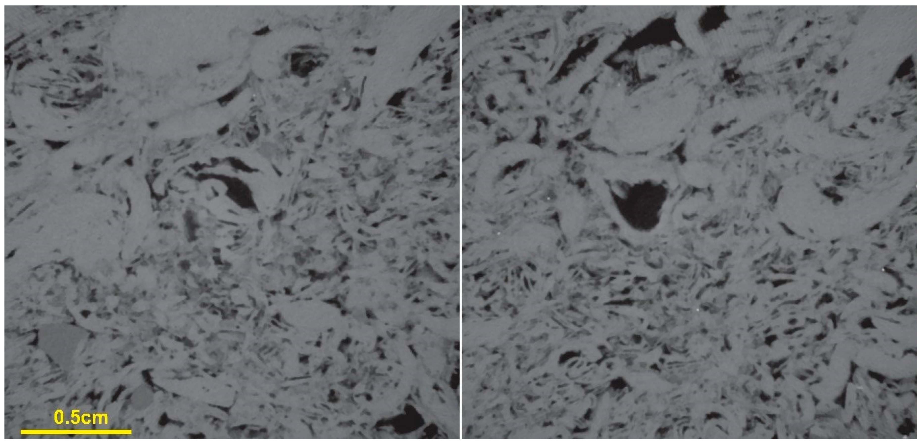
The sample was digitalized and 4304 microCT images were generated with 9.97 μm/voxel. During the processing, a non-local means filter [62] was used to smooth the image and remove artifacts from the acquisition process. After the image processing, it was possible to identify the different components of the rock. The shells and minerals described in the thin section appeared as different shades of grey. The pore space was identified as black and dark grey (Figure 2).
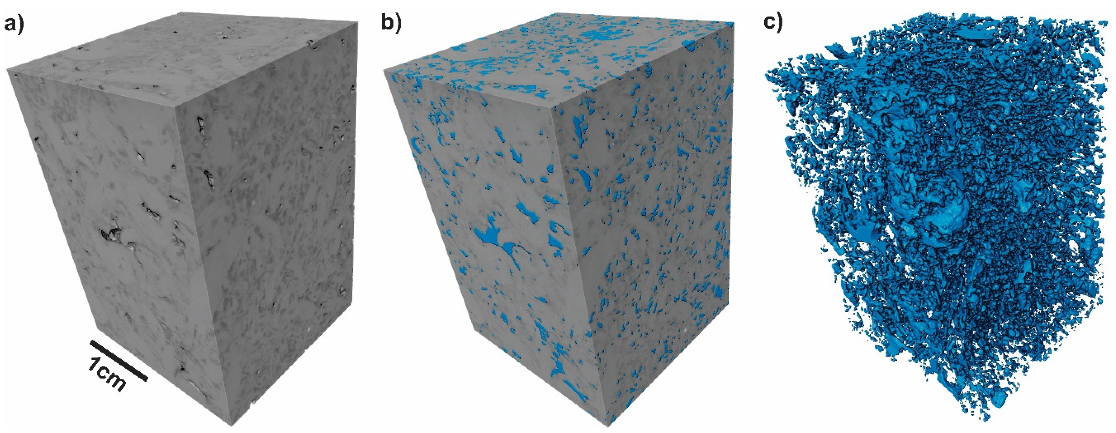
To produce the digital capillary pressure and relative permeability curves, it was necessary to segment the microCT images into pore and rock. For that, the Kittler and Illingworth method [63] was used. With the segmented images, the digital total porosity was calculated, and the value obtained was 15.3% for the whole digital sample (Figure 3). After that, a region of interest (ROI) was defined to be used in the simulation process.
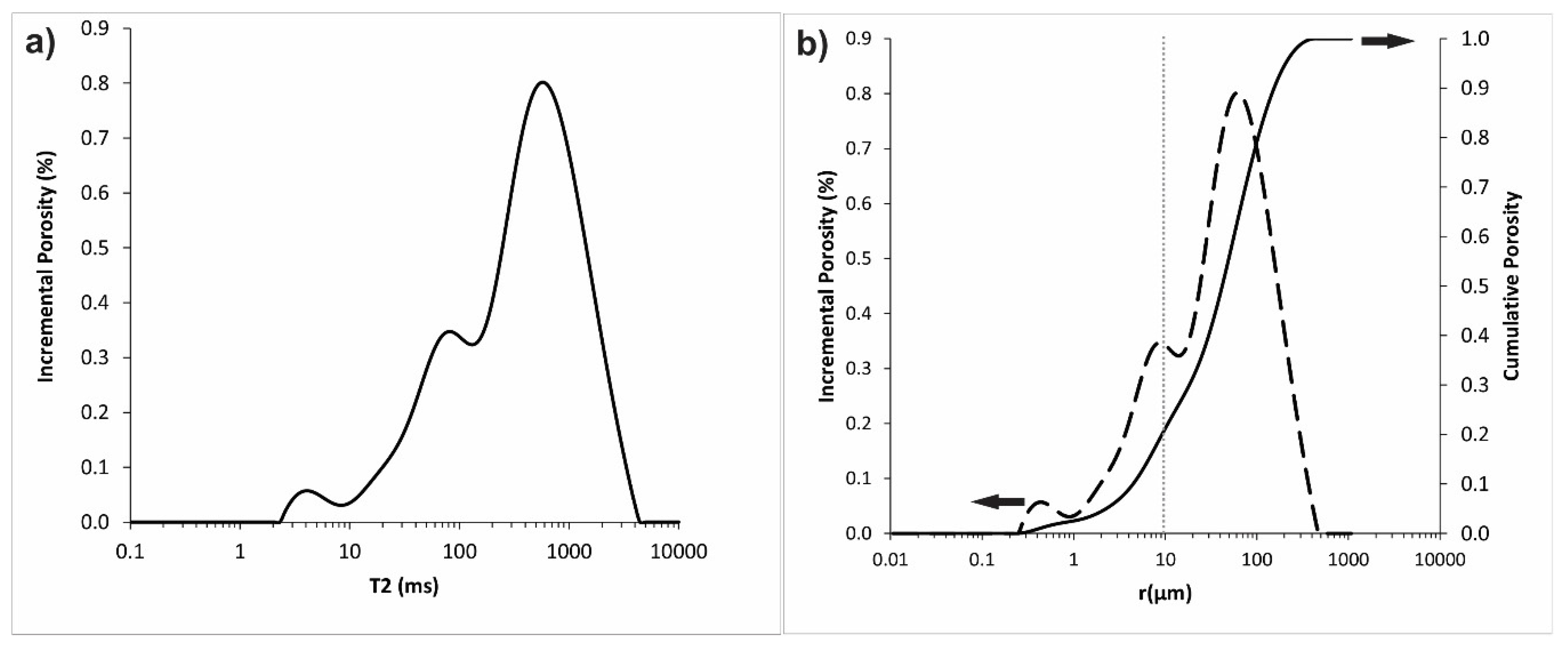
The NMR data acquisition, interpretation, and transformation of T2 to pore size distribution are discussed elsewhere [51]. It can be observed in Figure 4 that 82% of the pore size distribution had a radius larger than 10 µm, which means that the microCT images at a resolution of 9.97 µm captured the dominant porous space of this sample.

3.2. Contact Angle Measurements

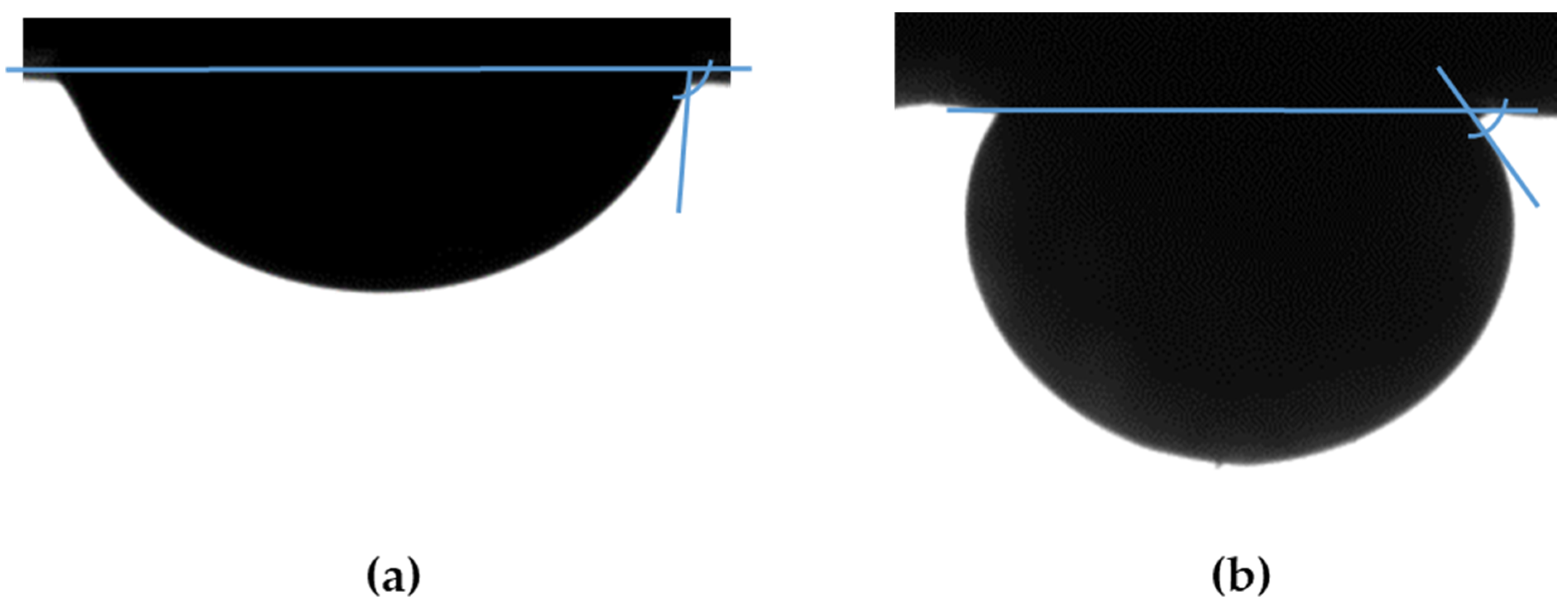
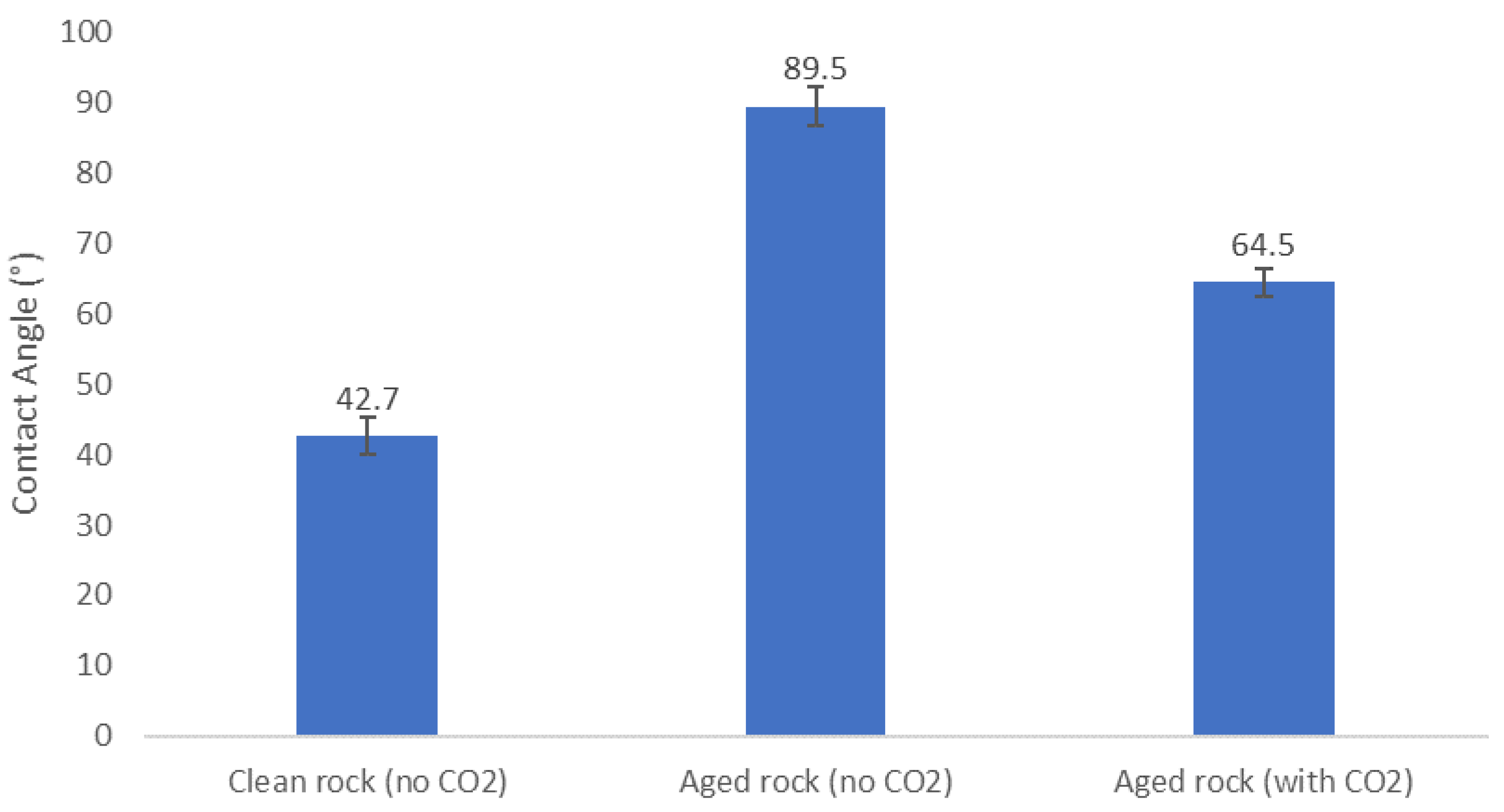
Equilibrium CA measurement tests were carried out on 15 day aged coquinas both in the absence of CO2 and using CO2-saturated fluids. As CA was measured toward the brine phase, lower CA values indicate a greater water-wet behavior. Figure 5 shows screenshots of the CA measurements, giving evidence of the change in wettability caused by CO2 dissolution in oil and brine.
In addition, CA was measured in unaged coquina samples without CO2 dissolution. Figure 6 illustrates the results of tests including aged and unaged coquinas in the presence or absence of CO2. It can be observed that, as expected, the unaged rock was water-wet, and aging shifted the wettability toward neutral-wet. In addition, CO2 injection reduced the CA, increasing the water-wet behavior of the coquina rock sample. These results will be discussed in Section 4.

3.3. Capillary Pressure and Relative Permeability Curves

The PORE simulations were performed on a sub-cube centered on the lower right quadrant comprising 1000 slices with a width of 1000 pixels and a height of 1000 pixels. A threshold of 56 was used, which yielded a porosity of 15.4% and permeability of 813 mD. At 9.97 microns per pixel resolution, the porosity compares favorably with the NMR porosity at a diameter greater than 10 microns (16.2%), and the computed permeability is close to the measured permeability of 765 mD.
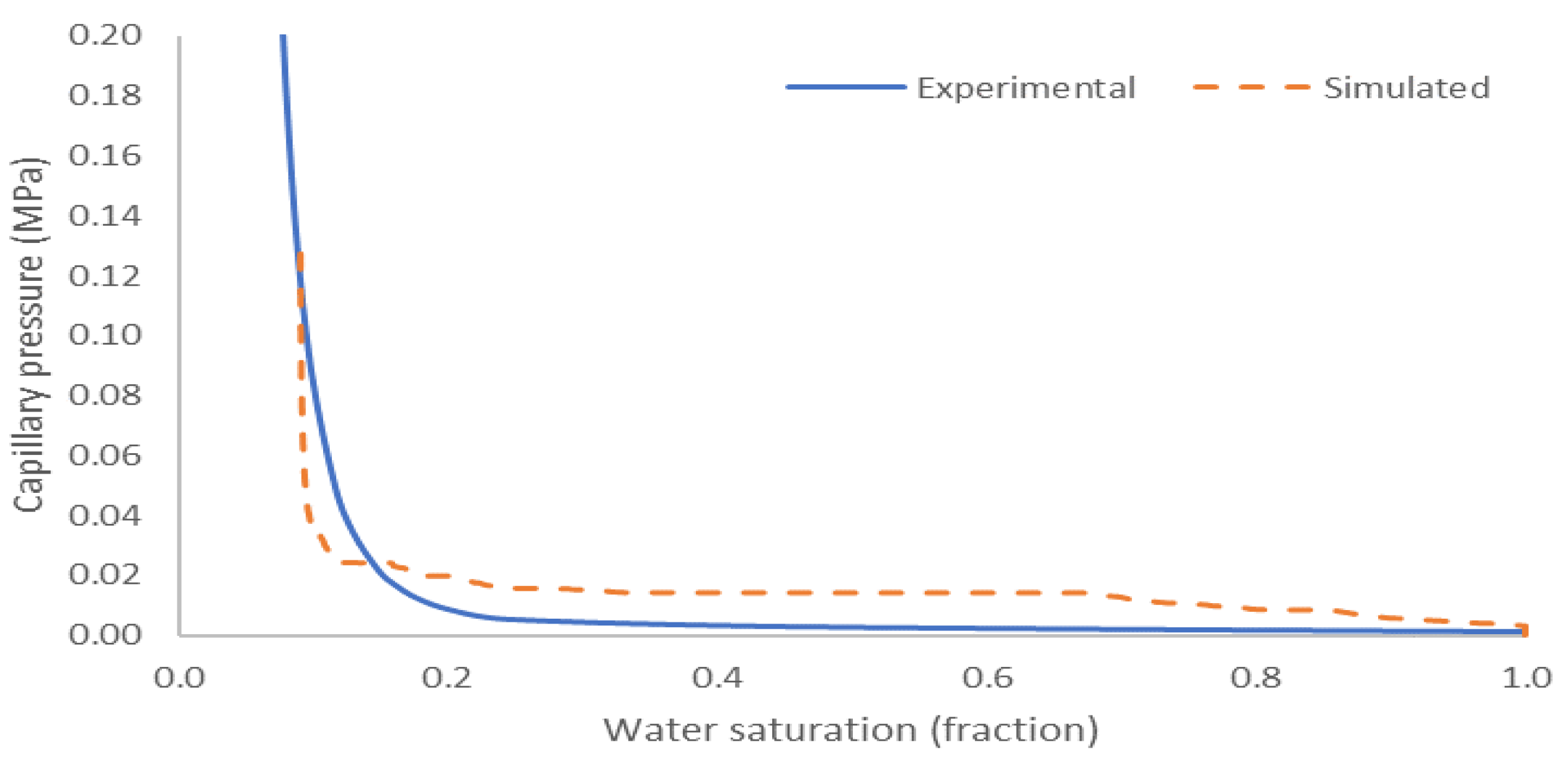
Primary drainage consists of the displacement of water by oil until reaching the connate water saturation. As the rock is fully saturated with brine and has not been in contact with oil prior to the primary drainage, the water-wet conditions of an unaged rock represent this stage [64]. Primary drainage capillary pressure curves were obtained experimentally and by numerical simulations using the procedures described in Section 2. Connate water saturation (Swi = 0.089) was obtained experimentally and used as input in the simulations for quality control. The contact angle value obtained in Section 3.3 for the unaged rock (CA = 42.7°) was considered. In addition, the experimentally measured interfacial tension for this oil-brine system with no CO2 content (IFT = 10.5 mN/m) previously reported by our group [43] was applied. Figure 7 shows good agreement between the experimental and simulated curves.
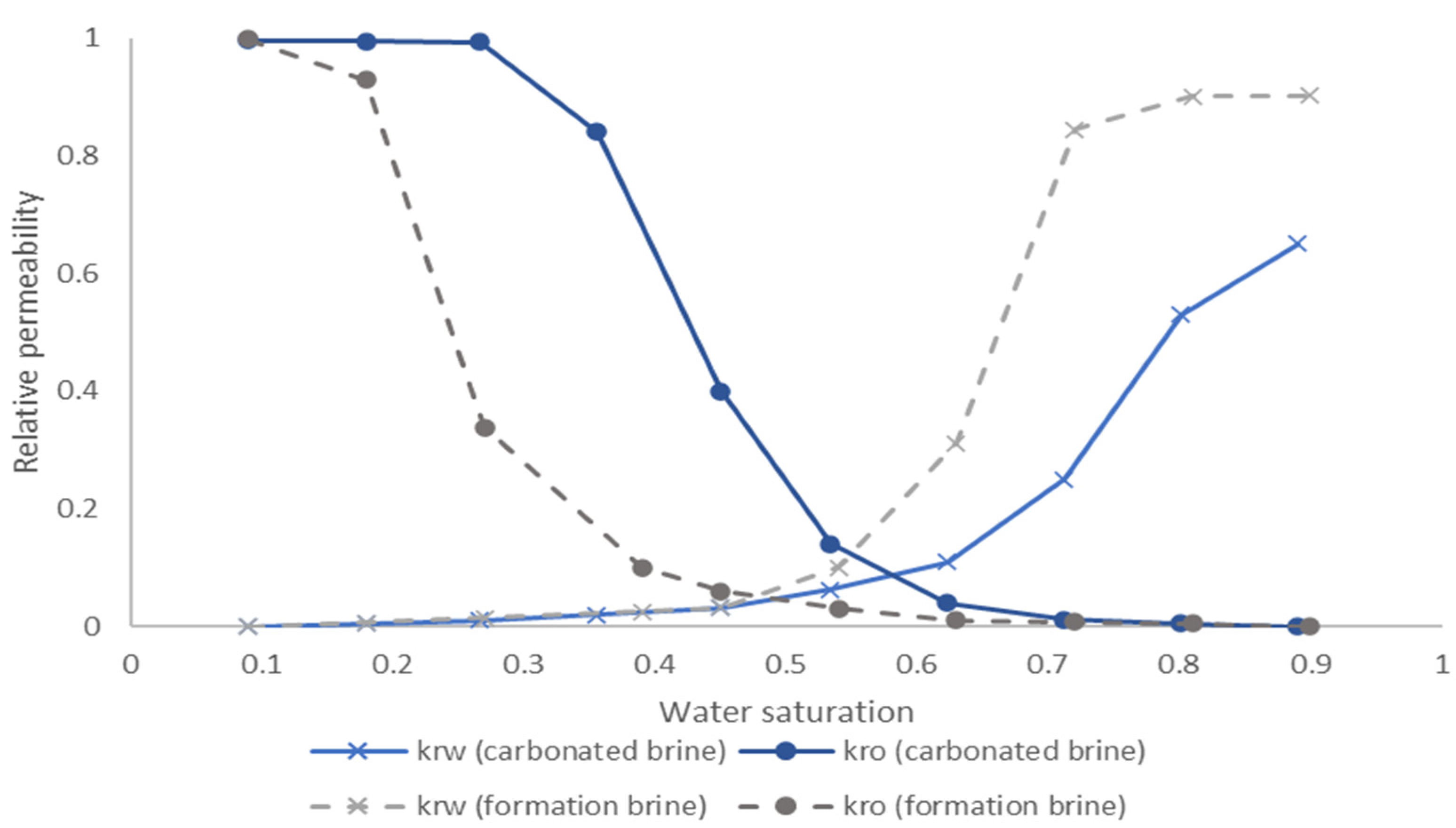
Imbibition, consisting of the displacement of oil by water, represents the oil recovery process. It starts with the rock saturated with oil (at connate water saturation) at oil-wet conditions [64]. To compare the effects of water injection and carbonated brine injection, the imbibition relative permeability curves were simulated using the experimentally measured CA and IFT values for each case. CA values are reported in Figure 6 in this work, and IFT values were presented and discussed in previous work by our group [43]. It should be noted that the objective of these curves is to qualitatively analyze the effects of wettability and IFT alteration due to CO2 injection on multiphase flow in the porous medium. They aim to support discussions regarding the effects of CO2 on fluid displacement. As the quantitative effects of mineral dissolution and reactive transport were not included in these simulations, they are not intended to provide quantitative input data for reservoir modelling.
Considering the results in Figure 6, the water injection case (with no CO2) indicated a neutral-wet (CA = 89.5°) rock and an IFT of 10.5 mN/m previously measured by our group [43]. By contrast, the carbonated brine injection case consisted of a water-wet rock (CA = 64.5°, Figure 6) and an IFT of 16.4 mN/m, as reported in the aforementioned study. The results are shown in Figure 8.

4. Discussion

The results presented in Section 3 give evidence that CO2 dissolution (i.e., by carbonated brine injection) shifts the wettability of the aged coquina sample from intermediate to water-wet. This reduction in oil-wet behavior is in agreement with previous studies of carbonated brine injection in carbonate rocks [33,34]. Several mechanisms were proposed to support this decrease in rock hydrophobicity. Sohrabi et al. [39] related this effect with the reduction in brine pH after CO2 dissolution. This affects surface charges at oil/water and water/solid interfaces and may destabilize polar compounds in the oil, reducing the oil-wet behavior of the rock. Chen et al. [37] studied the same problem by experimental CA measurements and surface complexation modelling. They associated pH reduction with the formation of positively charged species (i.e., >CaOH2+ for calcite surface and −NH2+ for oil surface), which causes surface repulsion, reducing the wettability toward oil. Drexler et al. [38] reported surface mineral dissolution and oil desorption to shift the wettability of oil-wet carbonate reservoir rocks. Zhu et al. [36] related the change in CA (toward water-wet) to element changes on the solid surface after introducing CO2 in the system. A reduction in carbon content on the rock surface, which could be associated with carbonate dissolution, resulted in an increase in hydrophilic behavior of the rock surface.
The wettability alteration caused by carbonated brine is a consequence of the effect of pH reduction on the oil/brine/rock interfaces. The TAN and TBN shown in Table 2 indicate that the oil used in this work contains both acid and basic compounds. The acid compounds are in the negatively charged dissociated state at intermediate or high pH [65]. In the absence of CO2, they interact with the positively charged surface of the carbonate rock, resulting in the intermediate-wet behavior observed for the aged sample. However, the acidic carbonated brine environment results in an increased concentration of the protonated acid components and a reduced concentration of their negatively charged dissociated species, reducing their interaction with the rock surface and, consequently, the wettability toward oil.
In addition, the increase in IFT for the carbonated brine (Section 3.3) also suggests a reduction in the interfacial activity of the polar compounds at lower pH values. Drexler et al. [43] measured the IFT for this oil and brine in the presence and absence of CO2 in triplicate experiments, and they found a 56% increase in IFT for the systems containing carbonated brine. In addition, they reported the same trends in experiments where the pH was controlled using buffer solutions. These results give evidence that the surface activity in this oil is controlled by its acid compounds. As a result, a higher concentration of the protonated acid compounds and a lower concentration of the deprotonated species results in a diminished surface-activity. This effect was explained by Danielli [66], who measured the IFT between different organic acids in bromobenzene solutions and water, controlling the pH with buffer solutions. For all the systems containing organic acids, the IFT was reduced when the pH was high enough to favor their dissociation. Furthermore, the reduction in IFT and concentration of surface-active species at increased pH for crude oils containing acid polar compounds was also described in previous works using CO2 dissolution [67] and acid/base buffers [68].
Besides the protonation of the acid compounds, basic compounds could also contribute to the observed wettability shift. In acidic environments, these compounds are positively charged due to protonation [69]. The presence of positively charged species at the oil/water interface induces repulsion with the positively charged surface of the carbonate rock, increasing its water-wet behavior.
Finally, chemical reaction between the rock and the carbonated brine can also play a part in the observed wettability alteration. Calcite, which is the major mineral constituent of the coquina rock samples [70], reacts with the carbonic acid formed by dissolution of CO2. This reaction increases the concentration of Ca2+, as described in the literature [33]. Furthermore, the potential determining ion Ca2+ was reported to weaken the interaction between positively charged surfaces of carbonates, such as chalk [71,72], and calcite [33], and the negatively charged compounds in the oil. As a result, the water-wet behavior is increased after CO2 dissolution in the aqueous phase.
Digital rock evaluations of carbonate rocks were presented in recent publications [73,74,75,76]. However, the coquina rock considered in this work presents a wide pore size distribution ranging from nanometers to hundreds of microns, as shown in Figure 4. To the best of our knowledge, this is the first study including the impact of carbonated brine on the imbibition relative permeabilities based on numerical experiments for a highly complex carbonate rock sample with a wide range of pore sizes. The curves obtained in this work (Figure 8) indicate the positive effect of carbonated brine injection on relative permeabilities. A shift in the crossover point toward higher water saturation indicates the increase in wettability toward water for carbonated brine injection [77]. This is also supported by the reduction in the endpoint relative permeability to water observed for the carbonated brine [78]. As a result, the obtained curves for carbonate brine injection illustrate an increased flow capacity (i.e., greater relative permeability) of the oil phase for the majority of saturation values.
Relative permeability curves play a critical role in oil recovery and EOR [79]. By applying appropriate upscaling techniques and considering mobility effects, capillary limit fractional flow curves can be obtained to estimate the flow of oil and brine under no macroscopic sweeping effects [80]. The shift in wettability previously discussed indicates an increase in oil displacement by carbonated brine injection, suggesting its potential for EOR applications.

5. Conclusions

Carbonated brine injection EOR is an effective method of reducing CO2 emissions in oil fields with high production of this gas. This work studies the effect of carbonated brine injection on the wettability and multiphase flow for a carbonate rock system analogous to Brazilian Pre-salt fields. Its main insights are summarized below:
Carbonated brine decreases the pH of the aqueous phase, favoring the protonation of acid and basic compounds in the oil. This induces an increase in the positive charge (or decrease in the negative charge) at the oil/brine interface and, consequently, increments the repulsion with the positively charged carbonate rock surface. As a result, the wettability is shifted toward water-wet.
MicroCT at 9.97 μm resolution captured 82% of the pore size distribution according to the NMR characterization, allowing the dominant system to be reproduced for pore-scale flow simulations.
Imbibition relative permeability curves obtained using pore network modelling for capillary limit immiscible flow showed changes in the curve crossover and endpoints in agreement with the wettability alteration found for carbonated brine injection. These changes contribute to increase the flow of oil, favoring its displacement for EOR processes. However, quantitative recovery calculations should also consider other effects, such as changes in mobility and brine–rock reactivity.

Author Contributions

Conceptualization, S.D. and F.H.; methodology, S.D., F.H. and W.G.; software, A.B.; validation, S.D., F.H., W.G. and A.B.; formal analysis, S.D., F.H., W.G. and A.B; investigation, S.D., F.H. and W.G.; resources, P.C.; data curation, S.D. and A.B.; writing—original draft preparation, S.D. and F.H.; writing—review and editing, S.D., F.H. and A.B.; visualization, S.D., F.H. and W.G.; supervision, S.D.; project administration, S.D. and P.C.; funding acquisition, P.C. All authors have read and agreed to the published version of the manuscript.

Funding

This research was funded by Shell Brasil, grant number ANP nº 20163-2.

Acknowledgments

This research was carried out in association with the ongoing R & D project registered as ANP nº 20163-2, “Análise Experimental da Recuperação de Petróleo para os Carbonatos do Pré-sal do Brasil através de Injeção Alternada de CO2 e Água” (UFRJ/Shell Brasil/ANP), sponsored by Shell Brasil under the ANP R & D levy as “Compromisso de Investimentos com Pesquisa e Desenvolvimento”. This study was financed in part by the Coordenação de Aperfeiçoamento de Pessoal de Nível Superior-Brasil (CAPES)—Finance Code 001.

Conflicts of Interest

The authors declare no conflict of interest.

References

  1. Kriegler, E.; Luderer, G.; Bauer, N.; Baumstark, L.; Fujimori, S.; Popp, A.; Rogelj, J.; Strefler, J.; van Vuuren, D.P. Pathways limiting warming to 1.5 °C: A tale of turning around in no time? Philos. Trans. R. Soc. A Math. Phys. Eng. Sci. 2018, 376, 20160457. [Google Scholar] [CrossRef] [PubMed] [Green Version]
  2. Mac Dowell, N.; Fennell, P.S.; Shah, N.; Maitland, G.C. The role of CO2 capture and utilization in mitigating climate change. Nat. Clim. Chang. 2017, 7, 243–249. [Google Scholar] [CrossRef] [Green Version]
  3. Guo, J.-X.; Huang, C.; Wang, J.-L.; Meng, X.-Y. Integrated operation for the planning of CO2 capture path in CCS–EOR project. J. Pet. Sci. Eng. 2020, 186, 106720. [Google Scholar] [CrossRef]
  4. Mohsin, I.; Al-Attas, T.A.; Sumon, K.Z.; Bergerson, J.; McCoy, S.; Kibria, M.G. Economic and Environmental Assessment of Integrated Carbon Capture and Utilization. Cell Rep. Phys. Sci. 2020, 100104. [Google Scholar] [CrossRef]
  5. Zhang, Z.; Pan, S.-Y.; Li, H.; Cai, J.; Olabi, A.G.; Anthony, E.J.; Manovic, V. Recent advances in carbon dioxide utilization. Renew. Sustain. Energy Rev. 2020, 125, 109799. [Google Scholar] [CrossRef]
  6. Berstad, D.; Nekså, P.; Gjøvåg, G.A. Low-temperature syngas separation and CO2 capture for enhanced efficiency of IGCC power plants. Energy Proc. 2011, 4, 1260–1267. [Google Scholar] [CrossRef] [Green Version]
  7. Aliff Radzuan, M.R.; Syarina, N.A.; Wan Rosdi, W.M.; Hussin, A.H.; Adnan, M.F. Sustainable Optimization of Natural Gas Sweetening Using A Process Simulation Approach and Sustainability Evaluator. Mater. Today Proc. 2019, 19, 1628–1637. [Google Scholar] [CrossRef]
  8. Vega, F.; Baena-Moreno, F.M.; Gallego Fernández, L.M.; Portillo, E.; Navarrete, B.; Zhang, Z. Current status of CO2 chemical absorption research applied to CCS: Towards full deployment at industrial scale. Appl. Energy 2020, 260, 114313. [Google Scholar] [CrossRef]
  9. Bui, M.; Adjiman, C.S.; Bardow, A.; Anthony, E.J.; Boston, A.; Brown, S.; Fennell, P.S.; Fuss, S.; Galindo, A.; Hackett, L.A.; et al. Carbon capture and storage (CCS): The way forward. Energy Environ. Sci. 2018, 11, 1062–1176. [Google Scholar] [CrossRef] [Green Version]
  10. Sanz-Pérez, E.S.; Murdock, C.R.; Didas, S.A.; Jones, C.W. Direct Capture of CO(2) from Ambient Air. Chem. Rev. 2016, 116, 11840–11876. [Google Scholar] [CrossRef]
  11. Webley, P.A. Adsorption technology for CO2 separation and capture: A perspective. Adsorption 2014, 20, 225–231. [Google Scholar] [CrossRef]
  12. Duan, J.; Jin, W.; Kitagawa, S. Water-resistant porous coordination polymers for gas separation. Coord. Chem. Rev. 2017, 332, 48–74. [Google Scholar] [CrossRef] [Green Version]
  13. Ahmed, I.; Jhung, S.H. Applications of metal-organic frameworks in adsorption/separation processes via hydrogen bonding interactions. Chem. Eng. J. 2017, 310, 197–215. [Google Scholar] [CrossRef]
  14. Staciwa, P.; Narkiewicz, U.; Sibera, D.; Moszyński, D.; Wróbel, R.J.; Cormia, R.D. Carbon Spheres as CO2 Sorbents. Appl. Sci. 2019, 9, 3349. [Google Scholar] [CrossRef] [Green Version]
  15. Deng, X.; Yang, W.; Li, S.; Liang, H.; Shi, Z.; Qiao, Z. Large-Scale Screening and Machine Learning to Predict the Computation-Ready, Experimental Metal-Organic Frameworks for CO2 Capture from Air. Appl. Sci. 2020, 10, 569. [Google Scholar] [CrossRef] [Green Version]
  16. Brunetti, A.; Scura, F.; Barbieri, G.; Drioli, E. Membrane technologies for CO2 separation. J. Memb. Sci. 2010, 359, 115–125. [Google Scholar] [CrossRef]
  17. Scholes, C.A.; Smith, K.H.; Kentish, S.E.; Stevens, G.W. CO2 capture from pre-combustion processes—Strategies for membrane gas separation. Int. J. Greenh. Gas Control 2010, 4, 739–755. [Google Scholar] [CrossRef] [Green Version]
  18. Belaissaoui, B.; Favre, E. Membrane Separation Processes for Post-Combustion Carbon Dioxide Capture: State of the Art and Critical Overview. Oil Gas Sci. Technol. Rev. IFP Energies Nouv. 2014, 69, 1005–1020. [Google Scholar] [CrossRef]
  19. Chi, C.; Wang, X.; Peng, Y.; Qian, Y.; Hu, Z.; Dong, J.; Zhao, D. Facile Preparation of Graphene Oxide Membranes for Gas Separation. Chem. Mater. 2016, 28, 2921–2927. [Google Scholar] [CrossRef]
  20. Celia, M.A.; Bachu, S.; Nordbotten, J.M.; Bandilla, K.W. Status of CO2 storage in deep saline aquifers with emphasis on modeling approaches and practical simulations. Water Resour. Res. 2015, 51, 6846–6892. [Google Scholar] [CrossRef]
  21. Gal, F.; Pokryszka, Z.; Labat, N.; Michel, K.; Lafortune, S.; Marblé, A. Soil-Gas Concentrations and Flux Monitoring at the Lacq-Rousse CO2-Geological Storage Pilot Site (French Pyrenean Foreland): From Pre-Injection to Post-Injection. Appl. Sci. 2019, 9, 645. [Google Scholar] [CrossRef] [Green Version]
  22. Jeong, S.-M.; Ko, S.; Sean, W.-Y. Numerical Prediction of the Behavior of CO2 Bubbles Leaked from Seafloor and Their Convection and Diffusion near Southeastern Coast of Korea. Appl. Sci. 2020, 10, 4237. [Google Scholar] [CrossRef]
  23. Pedro, J.; Araújo, A.A.; Moita, P.; Beltrame, M.; Lopes, L.; Chambel, A.; Berrezueta, E.; Carneiro, J. Mineral Carbonation of CO2 in Mafic Plutonic Rocks, I—Screening Criteria and Application to a Case Study in Southwest Portugal. Appl. Sci. 2020, 10, 4879. [Google Scholar] [CrossRef]
  24. Gou, Y.; Hou, Z.; Liu, H.; Zhou, L.; Were, P. Numerical simulation of carbon dioxide injection for enhanced gas recovery (CO2-EGR) in Altmark natural gas field. Acta Geotech. 2014, 9, 49–58. [Google Scholar] [CrossRef]
  25. Mazzotti, M.; Pini, R.; Storti, G. Enhanced coalbed methane recovery. J. Supercrit. Fluids 2009, 47, 619–627. [Google Scholar] [CrossRef]
  26. Iino, A.; Onishi, T.; Datta-Gupta, A. Optimizing CO2—And Field-Gas-Injection EOR in Unconventional Reservoirs Using the Fast-Marching Method. SPE Reserv. Eval. Eng. 2020, 23, 261–281. [Google Scholar] [CrossRef]
  27. Sheng, J. Enhanced Oil Recovery Field Case Studies; Gulf Professional Publishing: Waltham, MA, USA, 2013; ISBN 9780123865465. [Google Scholar]
  28. Thorne, R.J.; Sundseth, K.; Bouman, E.; Czarnowska, L.; Mathisen, A.; Skagestad, R.; Stanek, W.; Pacyna, J.M.; Pacyna, E.G. Technical and environmental viability of a European CO2 EOR system. Int. J. Greenh. Gas Control 2020, 92, 102857. [Google Scholar] [CrossRef]
  29. De Nevers, N. A Calculation Method for Carbonated Water Flooding. Soc. Pet. Eng. J. 1964, 4, 9–20. [Google Scholar] [CrossRef]
  30. Kechut, N.I.; Riazi, M.; Sohrabi, M.; Jamiolahmady, M. Tertiary Oil Recovery and CO2 Sequestration by Carbonated Water Injection (CWI). In Proceedings of the SPE International Conference on CO2 Capture, Storage, and Utilization, New Orleans, LA, USA, 10–12 November 2010; p. 12. [Google Scholar]
  31. Fjelde, I.; Asen, S.M. Wettability alteration during water flooding and carbon dioxide flooding of reservoir chalk rocks. In Proceedings of the SPE EUROPEC/EAGE Annual Conference and Exhibition, Barcelona, Spain, 14–17 June 2010. [Google Scholar]
  32. Al-Mutairi, S.M.; Abu-khamsin, S.A.; Hossain, M.E. A Novel Approach to Handle Continuous Wettability Alteration during Immiscible CO2 Flooding Process. In Proceedings of the Abu Dhabi International Petroleum Conference and Exhibition, Abu Dhabi, UAE, 11–14 November 2012. [Google Scholar]
  33. Seyyedi, M.; Sohrabi, M.; Farzaneh, A. Investigation of Rock Wettability Alteration by Carbonated Water through Contact Angle Measurements. Energy Fuels 2015, 29, 5544–5553. [Google Scholar] [CrossRef]
  34. Ruidiaz, E.M.; Winter, A.; Trevisan, O.V. Oil recovery and wettability alteration in carbonates due to carbonate water injection. J. Pet. Explor. Prod. Technol. 2018, 8, 249–258. [Google Scholar] [CrossRef]
  35. Teklu, T.W.; Alameri, W.; Kazemi, H.; Graves, R.M. Contact Angle Measurements on Conventional and Unconventional Reservoir Cores. In Proceedings of the Unconventional Resources Technology Conference, San Antonio, TX, USA, 20–22 July 2015; p. 17. [Google Scholar]
  36. Zhu, Z.; Li, M.; Lin, M.; Peng, B.; Sun, L.; Chen, L. Investigation on Variations in Wettability of Reservoir Rock Induced by CO2-Brine-Rock Interactions. In Proceedings of the SPE EUROPEC/EAGE Annual Conference and Exhibition, Vienna, Austria, 12–15 June 2011; p. 11. [Google Scholar]
  37. Chen, Y.; Sari, A.; Xie, Q.; Saeedi, A. Insights into the wettability alteration of CO2-assisted EOR in carbonate reservoirs. J. Mol. Liq. 2019, 279, 420–426. [Google Scholar] [CrossRef]
  38. Drexler, S.; Silveira, T.M.G.; De Belli, G.; Couto, P. Experimental study of the effect of carbonated brine on wettability and oil displacement for EOR application in the Brazilian Pre-Salt reservoirs. Energy Sources Part A Recover. Util. Environ. Eff. 2019, 1–15. [Google Scholar] [CrossRef]
  39. Sohrabi, M.; Emadi, A.; Farzaneh, S.A.; Ireland, S. A Thorough Investigation of Mechanisms of Enhanced Oil Recovery by Carbonated Water Injection. In Proceedings of the SPE Annual Technical Conference and Exhibition, Houston, TX, USA, 28–30 September 2015; p. 33. [Google Scholar]
  40. De Almeida, A.S.; Lima, S.D.T.C.; Rocha, P.S.; De Andrade, A.M.T.; Branco, C.C.M.; Pinto, A.C.C. CCGS opportunities in the Santos Basin pre-salt development. In Proceedings of the SPE International Conference on Health, Safety and Environment in Oil and Gas Exploration and Production 2010, Rio de Janeiro, Brazil, 12–14 April 2010; Volume 2, pp. 840–849. [Google Scholar]
  41. Pepin, A.; Bize-Forest, N.; Montoya Padilla, S.; Abad, C.; Schlicht, P.; de Castro Machado, A. Pre-Salt Carbonate Reservoir Analog Selection for Stimulation Optimization. In Proceedings of the International Petroleum Technology Conference, Kuala Lumpur, Malaysia, 10–12 December 2014. [Google Scholar]
  42. Pizarro, J.O.D.S.; Branco, C.C.M. Challenges in Implementing an EOR Project in the Pre-Salt Province in Deep Offshore Brasil. In Proceedings of the SPE EOR Conference at Oil and Gas West Asia, Muscat, Oman, 16–18 April 2012; p. 13. [Google Scholar]
  43. Drexler, S.; Correia, E.L.; Jerdy, A.C.; Cavadas, L.A.; Couto, P. Effect of CO2 on the dynamic and equilibrium interfacial tension between crude oil and formation brine for a deepwater Pre-salt field. J. Pet. Sci. Eng. 2020, 190, 107095. [Google Scholar] [CrossRef]
  44. Campos Neto, O.P.d.A.; Lima, W.S.; Cruz, F.E.G. Bacia de Sergipe-Alagoas (Sergipe-Alagoas Basin). Bol. Geocienc. da Petrobras 2007, 15, 405–415. [Google Scholar]
  45. Pettijohn, F.J. Sedimentary Rocks, 2nd ed.; Harper Brothers: New York, NY, USA, 1957; ISBN 978-1114189805. [Google Scholar]
  46. Schäfer, W. Ecology and Palaeoecology of Marine Environments; The University of Chicago Press: Chicago, IL, USA, 1972. [Google Scholar]
  47. Azambuja, N.C.; Arienti, L.M.; da Cruz, F.E. Guidebook to the Rift-Drift Sergipe-Alagoas Passive Margin Basin, Brazil, Proceedings of the The 1998 AAPG International Conference and Exhibition, Rio de Janeiro, Brazil, 8–11 November 1998; American Association of Petroleum Geologists: Tulsa, OK, USA, 1998; p. 113. [Google Scholar]
  48. Tavares, A.C.; Borghi, L.; Corbett, P.; Nobre-Lopes, J.; Câmara, R. Facies and depositional environments for the coquinas of the Morro do Chaves Formation, Sergipe-Alagoas Basin, defined by taphonomic and compositional criteria. Braz. J. Geol. 2015, 45, 415–429. [Google Scholar] [CrossRef]
  49. Corbett, P.W.M.; Estrella, R.; Morales Rodriguez, A.; Shoeir, A.; Borghi, L.; Tavares, A.C. Integration of Cretaceous Morro do Chaves rock properties (NE Brazil) with the Holocene Hamelin Coquina architecture (Shark Bay, Western Australia) to model effective permeability. Pet. Geosci. 2016, 22, 105–122. [Google Scholar] [CrossRef]
  50. Chinelatto, G.F.; Vidal, A.C.; Kuroda, M.C.; Basilici, G. A taphofacies model for coquina sedimentation in lakes (Lower Cretaceous, Morro do Chaves Formation, NE Brazil). Cretac. Res. 2018, 85, 1–19. [Google Scholar] [CrossRef]
  51. Hoerlle, F.O.; Rios, E.H.; de Azevedo Lopes da Silva, W.G.; Pontedeiro, E.M.B.D.; da Costa de Oliveira Lima, M.; Corbett, P.W.M.; Alves, J.L.D.; Couto, P. Nuclear Magnetic Resonance to Characterize the Pore System of Coquinas from Morro do Chaves Formation, Sergipe-Alagoas Basin, Brazil. Braz. J. Geophys. 2018, 36, 317–324. [Google Scholar] [CrossRef]
  52. da Costa de Oliveira Lima, M.; Martins, L.P.; Rios, E.H.; Boyd, A.; Pontedeiro, E.M.B.D.; Hoerlle, F.O.; Lipovetski, T.; Neto, A.O.; Mendes, M.; Borghi, L.; et al. Rock Typing of Coquinas from the Morro do Chaves Formation, Proceedings of the Sixteenth International Congress of the Brazilian Geophysical Society, Rio de Janeiro, Brazil, 17–22 August 2019; Brazilian Geophysical Society: Rio de Janeiro, Brazil, 2019; pp. 1–6. [Google Scholar]
  53. Coates, G.R.; Xiao, L.; Prammer, M.G. NMR Logging: Principles and Applications; Halliburton Energy Services: Houston, TX, USA, 1999; p. 234. [Google Scholar]
  54. Hassler, G.L.; Brunner, E. Measurement of Capillary Pressures in Small Core Samples. Trans. AIME 1945, 160, 114–123. [Google Scholar] [CrossRef]
  55. Albuquerque, M.R.; Eler, F.M.; Camargo, H.V.R.; Compan, A.L.M.; Cruz, D.A.; Pedreira, C.E. Estimation of Capillary Pressure Curves from Centrifuge Measurements Using Inverse Methods, Proceedings of the Rio Oil & Gas; IBP: Rio de Janeiro, Brazil, 24–27 September 2018. [Google Scholar]
  56. Silin, D.; Patzek, T. Pore space morphology analysis using maximal inscribed spheres. Phys. A Stat. Mech. Its Appl. 2006, 371, 336–360. [Google Scholar] [CrossRef]
  57. Dong, H. Micro CT Imaging and Pore Network Extraction; Imperial College London: London, UK, 2007. [Google Scholar]
  58. Zhou, D.; Blunt, M.; Orr, F.M. Hydrocarbon Drainage along Corners of Noncircular Capillaries. J. Colloid Interface Sci. 1997, 187, 11–21. [Google Scholar] [CrossRef] [PubMed]
  59. Raoof, A.; Hassanizadeh, S.M. A New Method for Generating Pore-Network Models of Porous Media. Transp. Porous Media 2010, 81, 391–407. [Google Scholar] [CrossRef] [Green Version]
  60. Joekar-Niasar, V.; Majid Hassanizadeh, S. Effect of fluids properties on non-equilibrium capillarity effects: Dynamic pore-network modeling. Int. J. Multiph. Flow 2011, 37, 198–214. [Google Scholar] [CrossRef]
  61. Blunt, M.J. Flow in porous media—Pore-network models and multiphase flow. Curr. Opin. Colloid Interface Sci. 2001, 6, 197–207. [Google Scholar] [CrossRef]
  62. Buades, A.; Coll, B.; Morel, J. A non-local algorithm for image denoising. In Proceedings of the 2005 IEEE Computer Society Conference on Computer Vision and Pattern Recognition (CVPR’05), San Diego, CA, USA, 20–25 June 2005; Volume 2, pp. 60–65. [Google Scholar]
  63. Kittler, J.; Illingworth, J. Minimum error thresholding. Pattern Recognit. 1986, 19, 41–47. [Google Scholar] [CrossRef]
  64. Blunt, M.J. Multiphase Flow in Permeable Media: A Pore-Scale Perspective; Cambridge University Press: Cambridge, UK, 2017; ISBN 9781107093461. [Google Scholar]
  65. Werner, J.; Persson, I.; Björneholm, O.; Kawecki, D.; Saak, C.-M.; Walz, M.-M.; Ekholm, V.; Unger, I.; Valtl, C.; Caleman, C.; et al. Shifted equilibria of organic acids and bases in the aqueous surface region. Phys. Chem. Chem. Phys. 2018, 20, 23281–23293. [Google Scholar] [CrossRef] [PubMed] [Green Version]
  66. Danielli, J.F. The Relations between Surface pH, Ion Concentrations and Interfacial Tension. Proc. R. Soc. Lond. Ser. B Biol. Sci. 1937, 122, 155–174. [Google Scholar]
  67. Lashkarbolooki, M.; Riazi, M.; Ayatollahi, S. Effect of CO2 and natural surfactant of crude oil on the dynamic interfacial tensions during carbonated water flooding: Experimental and modeling investigation. J. Pet. Sci. Eng. 2017, 159, 58–67. [Google Scholar] [CrossRef]
  68. Lashkarbolooki, M.; Ayatollahi, S. The effects of pH, acidity, asphaltene and resin fraction on crude oil/water interfacial tension. J. Pet. Sci. Eng. 2018, 162, 341–347. [Google Scholar] [CrossRef]
  69. Buckley, J.S.; Takamura, K.; Morrow, N.R. Influence of Electrical Surface Charges on the Wetting Properties of Crude Oils. SPE Reserv. Eng. 1989, 4, 332–340. [Google Scholar] [CrossRef]
  70. Drexler, S.; Hoerlle, F.O.; Silveira, T.M.G.; Cavadas, L.A.; Couto, P. Impact of Rock Aging Time on the Initial Wettability of Minerals and Analogue Rocks Using Pre-Salt Fluids Under Reservoir Conditions. In Proceedings of the Offshore Technology Conference Brasil, Rio de Janeiro, Brazil, 29–31 October 2019; p. 8. [Google Scholar]
  71. Strand, S.; Høgnesen, E.J.; Austad, T. Wettability alteration of carbonates—Effects of potential determining ions (Ca2+ and SO42−) and temperature. Colloids Surf. A Physicochem. Eng. Asp. 2006, 275, 1–10. [Google Scholar] [CrossRef]
  72. Austad, T.; Strand, S.; Madland, M.V.; Puntervold, T.; Korsnes, R.I. Seawater in Chalk: An EOR and Compaction Fluid. SPE Reserv. Eval. Eng. 2008, 11, 648–654. [Google Scholar] [CrossRef]
  73. Tölke, J.; Baldwin, C.; Mu, Y.; Derzhi, N.; Fang, Q.; Grader, A.; Dvorkin, J. Computer simulations of fluid flow in sediment: From images to permeability. Lead. Edge 2010, 29, 68–74. [Google Scholar] [CrossRef]
  74. Dernaika, M.R.; Sahib, M.R.; Gonzalez, D.; Mansour, B.; Al Jallad, O.; Koronfol, S.; Sinclair, G.; Kayali, A. Core Characterization and Numerical Flow Simulation in Representative Rock Types of the Raudhatain Field in Kuwait. In Proceedings of the SPE Kuwait Oil & Gas Show and Conference, Kuwait City, Kuwait, 15–18 October 2017; p. 24. [Google Scholar]
  75. Zambrano, M.; Tondi, E.; Mancini, L.; Lanzafame, G.; Trias, F.X.; Arzilli, F.; Materazzi, M.; Torrieri, S. Fluid flow simulation and permeability computation in deformed porous carbonate grainstones. Adv. Water Resour. 2018, 115, 95–111. [Google Scholar] [CrossRef] [Green Version]
  76. AlJallad, O.; Dernaika, M.; Koronfol, S.; Naseer Uddin, Y.; Mishra, P. Evaluation of Complex Carbonates from Pore-Scale to Core-Scale. In Proceedings of the International Petroleum Technology Conference, Dhahran, Kingdom of Saudi Arabia, 13–15 January 2020; p. 21. [Google Scholar]
  77. Craig, F.F. The Reservoir Engineering Aspects of Waterflooding; Henry, L., Doherty, H.L., Eds.; Memorial Fund of AIME: Richardson, TX, USA, 1971; ISBN 9780895202024. [Google Scholar]
  78. Anderson, W.G. Wettability Literature Survey Part 5: The Effects of Wettability on Relative Permeability. J. Pet. Technol. 1987, 39, 1453–1468. [Google Scholar] [CrossRef]
  79. Lake, L.W. Enhanced Oil Recovery; Prentice Hall: Upper Saddle River, NJ, USA, 1989; ISBN 9780132816014. [Google Scholar]
  80. Picchi, D.; Battiato, I. Relative Permeability Scaling From Pore-Scale Flow Regimes. Water Resour. Res. 2019, 55, 3215–3233. [Google Scholar] [CrossRef]
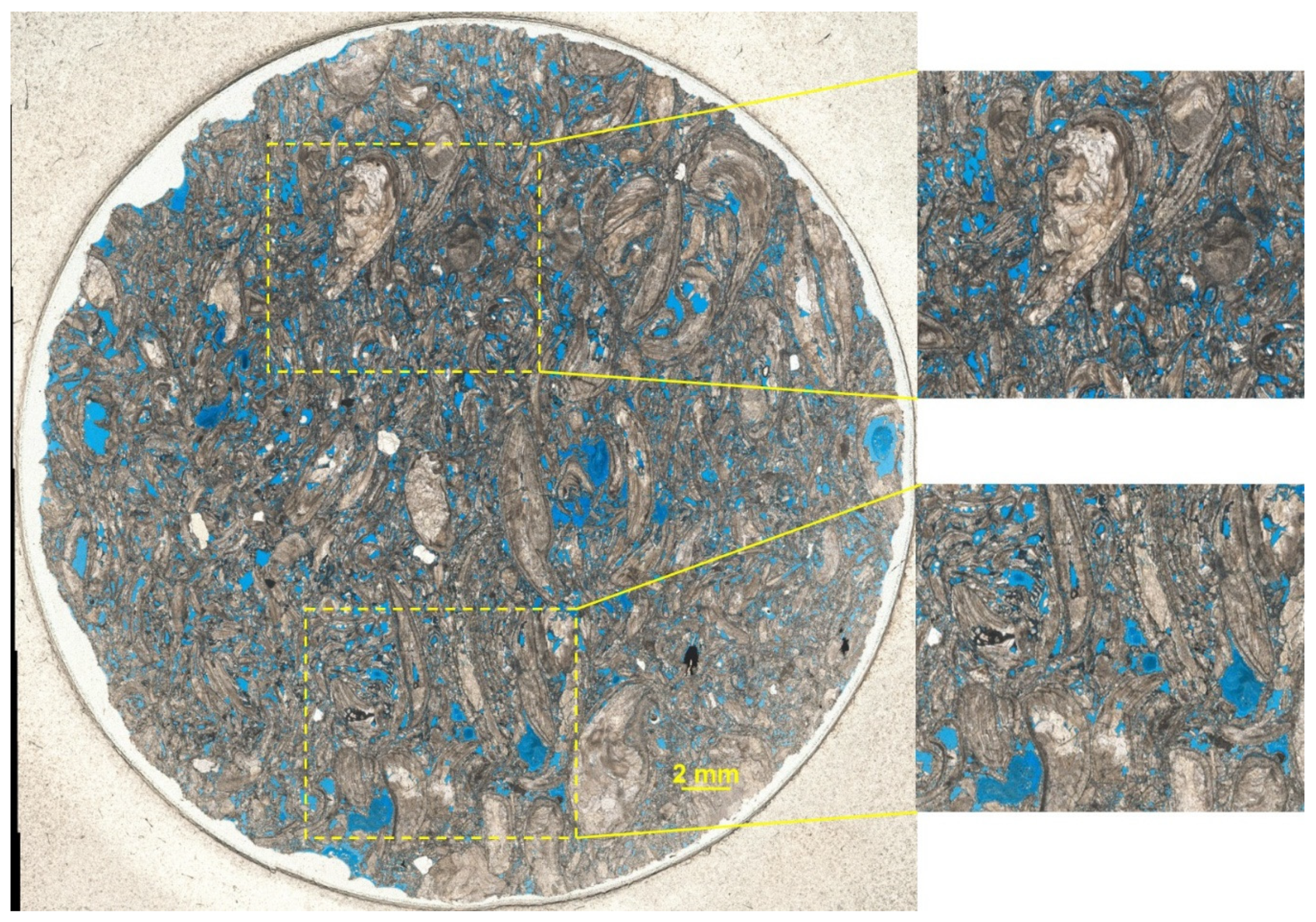
Figure 1. Thin section of coquina sample classified as a grainstone. With the zoomed images on the right, it is possible to observe the different pore types and the heterogeneity of the rock constituents. Magnification of 2.5 times.
Applsci 10 06496 g001
Figure 2. Slices from the micro-computed tomography (microCT) coquina sample with a pixel size of 9.98 µm.
Applsci 10 06496 g002
Figure 3. The volume of interest used in the digital sample. (a) microCT images of the coquina, and (b) rock matrix in grey and segmented pores in blue. (c) Segmented pore system.
Applsci 10 06496 g003
Figure 4. Nuclear Magnetic Resonance (NMR) data from the studied coquina sample. (a) shows the T2 distribution and (b) illustrates the incremental (dashed curve) and cumulative (full curve) pore size distributions. The vertical dashed line shows the microCT pixel size (9.97 µm). Pores larger than this value are captured in the digital image. By contrast, pores with a radius smaller than this value are under the image resolution.
Applsci 10 06496 g004
Figure 5. Images illustrating contact angle measurements. (a) Measurement on an aged rock with no CO2. (b) Measurement on aged coquina using CO2-saturated fluids. Images captured after 24 h of experiment.
Applsci 10 06496 g005
Figure 6. Equilibrium contact angles between Pre-salt crude oil and formation brine on clean and 15 day aged coquinas. The test with CO2 considers oil and brine saturated with CO2. Experiment conditions: 60 °C and 6.895 MPa. The reported value is the mean of triplicate measurements, and the error bars represent the standard error of the mean.
Applsci 10 06496 g006
Figure 7. Experimental and numerical simulated primary drainage capillary pressure curves for the coquina sample considered in this work.
Applsci 10 06496 g007
Figure 8. Imbibition relative permeability curves for water (gray) and carbonated brine (blue) injection in the oil-saturated coquina sample.
Applsci 10 06496 g008
Table 1. Formation brine composition and total dissolved solids (TDS).
IonsConcentration [mg/L]
Na+57,580
Ca2+24,250
Mg2+2120
K+1200
Ba2+24
Sr2+1260
SO42−54
Cl139,900
TDS226,388
Table 2. Crude oil characterization.
Crude Oil Properties
Saturates (wt.%)64.06
Aromatics (wt.%)25.98
Resins (wt.%)8.46
Asphaltenes (wt.%)1.50
Total Acid Number (mg KOH/g)0.37
Total Base Number (mg KOH/g)4.00
Table 3. Routine petrophysics of the studied coquina sample.
SamplePore
Volume (cc)
Porosity
(%)
Permeability
(mD)
Grain
Density (g/cc)
Diameter
(cm)
Length
(cm)
Weight
(g)
Coquina6.819.8765.12.693.53.674.3