1. Introduction
With the global concern about rising greenhouse-gas emissions due to fossil-fuel-based power generation, electricity production using eco-friendly energy sources is becoming increasingly important. Ambient or aeroelastic vibration—one of the eco-friendly energy sources being explored as an alternative to conventional fuel sources—has attracted the attention of many researchers over the past decade. The conversion of vibration into electricity is characterized mainly by electrostatic, electromagnetic, or piezoelectric transduction mechanisms, which can be used to obtain electricity through a variety of acquisition methods [
1,
2,
3]. Studies on the conversion of vibration mechanical energy into electrical energy have been conducted using various types of vibration sources. These vibration sources can be from a variety of environments, including large architectural structures such as bridges, buildings, industrial equipment, home appliances, train railroads, cars, and airplanes [
4]. Recently, following the trend of realizing autonomous energy-harvesting devices such as self-powered wireless sensors using roads, floor tiles, or bikes, the utilization of the vibration created by people has been investigated [
5,
6,
7]. Among these sources, large architectural structures, such as bridges and buildings, utilize traffic-induced vibrations, seismic events, or wind-induced vibrations. They produce vibration-sourced electricity mainly through electromagnetic conduction mechanisms or mechanisms using piezoelectric materials. The tensile membrane architecture (TMA), which is the means of electricity production introduced in this paper, is an architectural structure that is classified into the same category of vibration sources as buildings and bridges but has not been utilized previously for vibration-generated electricity. It uses the same type of vibration that acts on a building or bridge and is characterized by energy collection using wind-induced vibration generated in the membrane. An example of electricity generation using a membrane is the energy-harvesting eel developed by Allen et al. [
8], which confirms the feasibility of the energy-harvesting TMA.
The TMA is a thin membrane structure with a unique surface shape and large deflection behavior that can support a structural load. TMAs are built in a wide range of sizes and for different purposes, including large structures, e.g., the Otto and Behnisch and Partners’ Munich Olympic Stadium (1972), the traditional Mongolian ger, and a camping tent. An identifying feature of the TMA is that its entire structure (or part of it, such as a roof or wall) is wrapped with a tensile membrane cladding, such as fabric or foil. Compared to compression members, the most significant advantage of the TMA is that it can be as thin and as light as possible as long as the required prestress level is maintained [
9]. Because of recent developments in technology and materials, a flatter shape rather than a highly curved shape for the architecture and adjusting the prestressing forces can be realized; and new attempts to develop TMAs are being made from existing research [
10,
11]. The results from these studies indicate that as the technology advances, the application fields of TMAs will be expanded. Because TMA has a negligible bending and compression stiffness, the fluttering of the membrane is superior to that for typical building materials, resulting in an environment where ambient vibration or wind-induced vibration is likely to occur. The concept of generating electricity through the application of an energy-harvesting technique to the TMA was first presented in our previous paper [
12]. In the present paper, we describe the optimization of energy-harvestable TMAs for two regions with the highest offshore wind-farm electricity production.
The objective of this study was to determine which TMA geometry yields the optimal electricity generation and stability in a specific region. An experiment involving two offshore regions with the highest wind-power-generation capacity in the world—Inner Mongolia (in China) and Texas (in the USA)—was performed. The optimization technique developed can help researchers in selecting the TMA type and material suitable for specific areas and evaluating the suitability of energy harvesting in these areas via the TMA. The simulation software used to achieve the objective was designed with two main goals: (1) to create design variations for the three basic types of TMAs, i.e., hyperbolic paraboloid (hypar), conic, and barrel vault, and (2) to infer the amount of electricity obtained from each alternative in three wind-frequency environments. This study was based on the work of Maeng and Hyun [
12]. A total of 18 optimization results are herein presented for three shapes (hypar, conic, and barrel vault), three wind-frequency environments, and two regions.
3. Methodology
The goal of the experiments performed in this study was to identify the TMA with the optimal power-generation and material-stiffness values for the wind environments of Inner Mongolia (in China) and Texas (in the USA), which are the regions of the world with the largest amounts of offshore wind generation. Thus, a total of 18 optimizations were performed, for 2 regions (Inner Mongolia and Texas); for three wind patterns (low-frequency, medium-frequency, and high-frequency); and for three basic types of TMAs (hypar, conic, and barrel vault). The Grasshopper plug-in Kangaroo [
32] was used to implement the computational model of the TMA, and the Grasshopper plug-in Wallacei X [
33], which employs the NSGA-2 algorithm [
34] as the primary evolutionary algorithm, was used for the optimization.
3.1. Simulation Procedures
Multi-objective Pareto-optimization was performed with the objectives of maximizing the material stiffness and electric generation and determining the optimal stability and generated amount of electricity. The optimization was performed in the following order. First, the area where the TMA was to be built was selected; each region had different wind patterns, according to the average wind speed and wind direction. Second, the geometry of the TMA was defined using three parameters: the stiffness of the material, shape, and orientation. Third, the energy generated from the TMA when the wind blew for a certain period of time was calculated. Finally, a multiobjective Pareto-optimization algorithm was implemented with the objectives of power generation and material stiffness. The details of each step are presented in the following sections.
3.2. Configuration for Genes: Wind Pattern
This section explains in detail the process of defining the wind pattern of a target area. In the present study, the wind pattern corresponding to the “Wind” component of the simulation, which was a combination of the “WindVector” and “Amplitude” components, was derived from the 2019 data of the Global Wind Atlas [
35]. To differentiate it from the previous paper [
12] that did not consider the change of the WindVector, the Wind component was designed in consideration of the specificity of each region; the aim was finding a suitable TMA for the region.
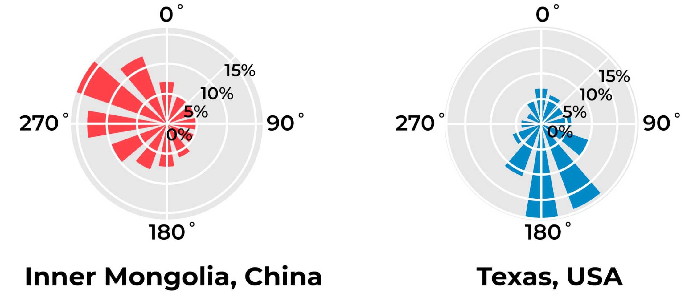
Figure 1 and
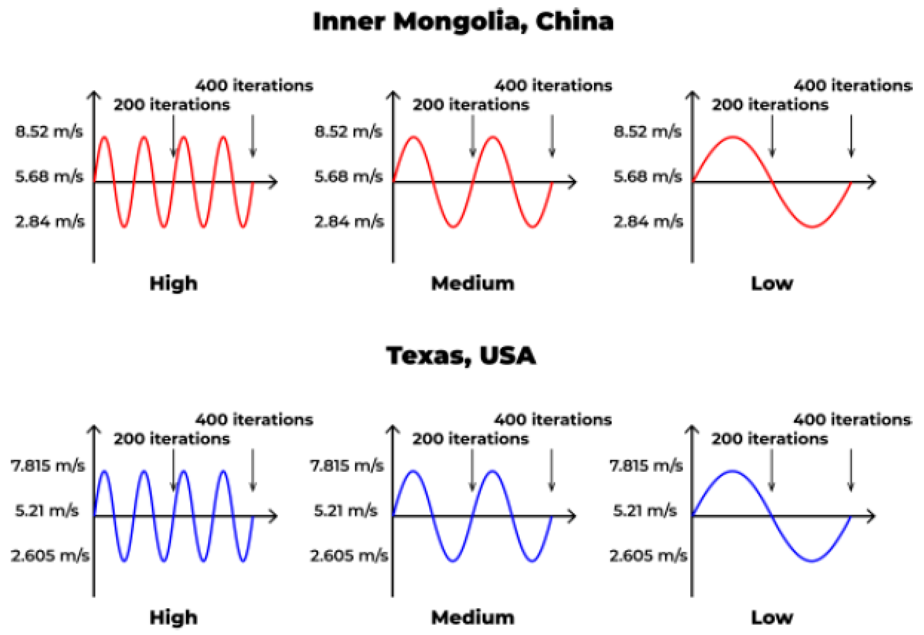
Figure 2 present the average annual wind speeds and wind directions measured at heights of 10 m in Inner Mongolia and Texas. The wind rose in
Figure 1 indicates the horizontal direction probabilities in which the wind blew in a circular manner. The wind-direction value in the simulation was determined according to the probability of wind direction, and the WindVector parameter of the Wind component was then applied.
Figure 2 presents the wind speed model applied to the experiment; a periodic wind pattern was used. This sine-shaped model started at the annual average wind speed value of the target region and had an amplitude equal to 50% of the annual average wind speed. However, Kangaroo performed the simulation according to a unit of time called “iteration,” which was different from the actual time; thus, the
x-axis of the wind speed graph was based on iterations rather than the actual time. The program was set to perform 400 iterations per simulation, and accordingly, the period of the sine wave of the wind speed was classified into three types: low, medium, and high. Even in the same region, the wind frequency will be different depending on the surrounding environment, season, and time. Because this study did not focus on implementing the accurate wind pattern corresponding to each region, the wind pattern was simplified to present various environment conditions by using three different periodic frequencies. The focus was on the variation of the TMA performance for the same average wind speed and direction in the region. According to these types, the sine wave was drawn once, twice, and four times throughout the 400 iterations. Additionally, the speed, i.e., the y-axis of the wind speed graph, was converted into pressure (in Pascals) and applied as the Amplitude parameter of the Wind component. Therefore, Wind was the result of a combination of the wind direction, i.e., WindVector and the wind speed, i.e., Amplitude. All simulations were performed under the assumption that ambient conditions were negligible, to focus on the geometry under the given wind conditions.
For the implementation of the wind pattern, the Wind component consisting of the wind direction, i.e., WindVector, and wind speed, i.e., Amplitude, was set, and Kangaroo calculated the changes in the wind direction and speed over 10 iterations (Kangaroo’s unit of time). Kangaroo counts 10 iterations by default when drawing a solution on the screen. Thus, assuming the actual time, like the wind direction and speed change once per second, the simulation was designed to change the wind direction and speed once per 10 iterations. The value of WindVector varied every 10 iterations according to the region (
Figure 1), regardless of the frequency type, but the value of Amplitude varied every 10 iterations according to the frequency type (
Figure 2). The default calculation value for drawing a solution was defined as 10 iterations; thus, 400 iterations were the time taken for Kangaroo to calculate a total of 40 TMA movements. Kangaroo generated a sine graph once during 100 iterations (10 calculations) at a high frequency, once during 200 iterations (20 calculations) at a medium frequency, once during 400 iterations (40 calculations) at a low frequency. The actual runtime for completing an alternative with a total of 400 iterations was between 2 min and 3 min. An optimization of 30 generations with a population size of 25 took approximately 30 to 45 h (the hypar and conic simulations took the smallest and largest amounts of time, respectively). Increasing the number of iterations per simulation made the acceleration value more accurate, but considering the computational cost, the calculation time was too long. However, if the number of iterations is reduced, the difference in the acceleration value will be reduced, making a comparison difficult.
3.3. Configuration for Genes: Geometry
This section introduces the parameters that determine the TMA geometry: shape, material stiffness, and orientation. First, the three types of shapes (hypar, conic, and barrel vault) are introduced. Because the three types differ with respect to the structural features and the major factors affecting the structure, the experiments were conducted separately [
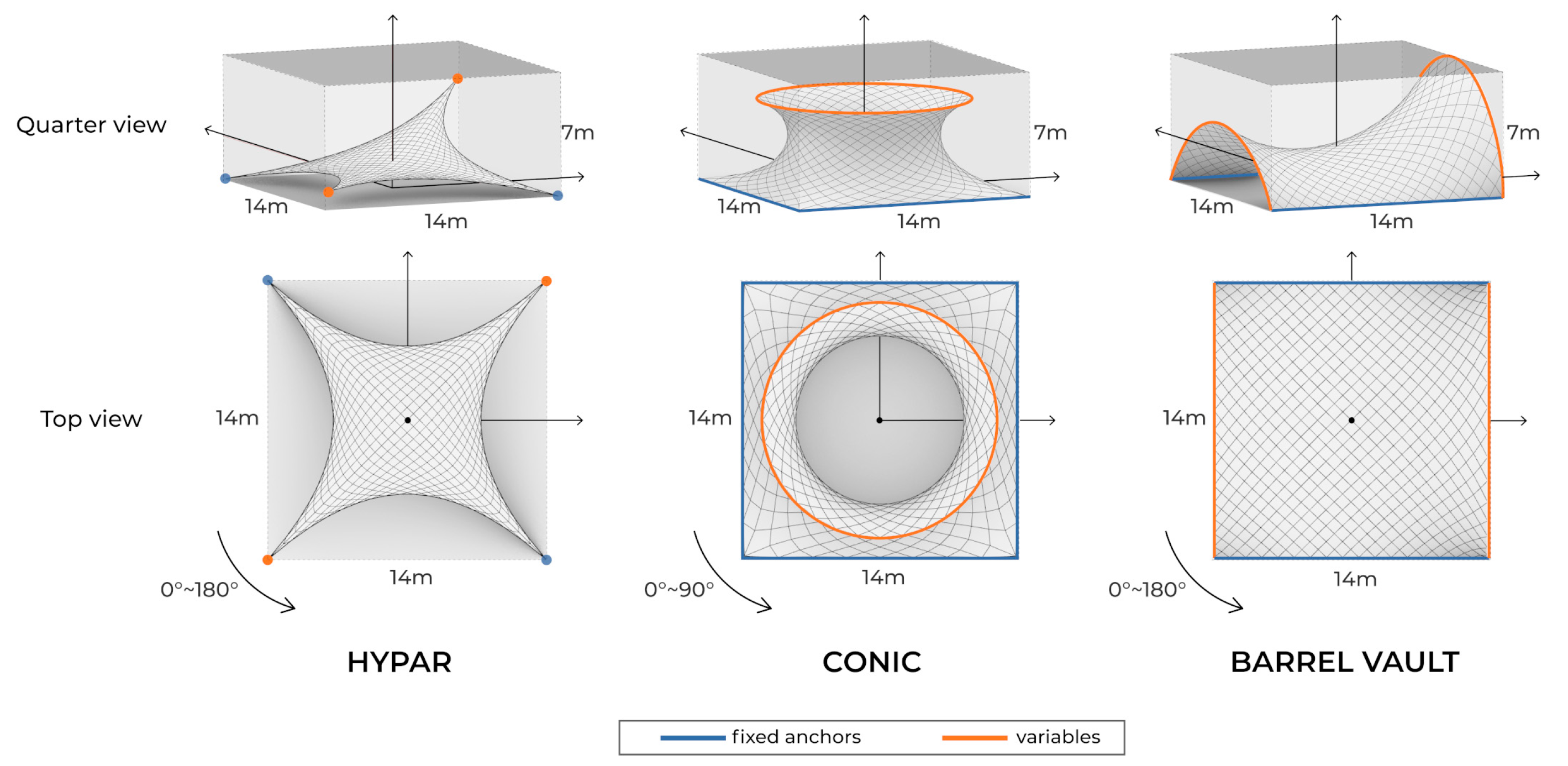
30]. A 14 × 14 × 7 m bounding box was assumed, and the three aforementioned types of TMAs were formed within the bounding zone (
Figure 3). The orientation, compared with our previous research [
12], was a newly added variable, while the rest of the bounding box and TMA shape variables were under the same conditions.
The hypar shape has alternating high and low support points, and the most basic hypar shape comprises two high points and two low points. More complex hypars may have larger numbers of supports, but in the present simulation, optimization was performed on a hypar with only four supports, two of which were placed diagonally and fixed to the bottom, and the other two were unfixed supports located in the range of 0–7 m along the z-axis.
“Conic” refers to a structure consisting of a head ring and a square base support. In the case of the conic shape, the membrane fails if the minimum surface and the desired shape differ [
36]. Head ring height and radius values were determined according to the feasible ranges identified by Bridgens et al. [
36]. Thus, to satisfy the feasible bounds, the radius was fixed within the range of 0–7 m, and the height was determined to be between 0 and 7 m.
Barrel vault consisted of two elliptical curves located at the ends of two parallel lines. The lengths of the parallel straight lines were both 14 m, the distance between them was fixed at 14 m, and the y-radius of each of the two ellipses was in the range of 0–7 m.
All alternatives of the three types of TMAs could be rotated around the center. To prevent the overlap of the geometry due to rotation, the turning radii for the hypar and barrel-vault shapes were <180°, and that for the conic shape was <90°. The rotation angle of the TMAs was defined as “Orientation” and determined which side of the structure was facing the wind. The main direction of the winds is different in Inner Mongolia versus Texas; orientation was the parameter which determined the direction of the TMA geometry that can have the maximum energy generation.
To apply the stiffness of the membrane material to the simulation, a brief calculation method of Kangaroo was used, wherein the solver regards the membrane surface as multiple spring objects linked to each other. As shown in
Figure 3, hundreds of springs comprised a curved membrane, and these springs were used to reach the desired length with a specific strength. According to Piker [
32], the spring objects follow Hooke’s law; i.e., the spring strength is calculated as EA/L, where E represents Young’s modulus, A represents the cross-sectional area of the spring, and L represents the resting length. The stiffness range in the simulation was determined according to measurement data from the research of Uhlemann [
37]. The two most commonly used membrane materials from his study—polyester fiber and glass fiber—had longitudinal stiffness of 25,200 and 54,720 N/cm, respectively. In the simulation, warp and weft elastic modulus was supposed to be identical and an available material stiffness range was determined. The stiffness range was modified by the minimum and maximum of the Young’s modulus of the two materials, referred from the Uhlemann’s study [
37], and the formula to get longitudinal stiffness from Young’s modulus was used. The stiffness range was established from the minimum value of polyester fiber’s stiffness to the maximum value of glass fiber’s stiffness and calculated as 1200 to 6840 kN/m, respectively. The target lengths of the springs were similar, with little dependence on the structural characteristics of the three TMAs. As shown in
Figure 3, for the hypar shape, because the supports of the structure are in the form of points, all the springs aim to be half the length of the plane before form-finding starts. For the conic and barrel-vault shapes, because the supports are in the form of lines, the outline corresponding to the supports has the same length as the plane before the form-finding. The rest of the springs aim to be half the length. Eventually, the material stiffness was expressed as a design variable composed of the target length and the strength of the springs.
3.4. Configuration for Goals
The simulation had two objectives: maximization of the acceleration and stiffness. These terms are defined in the following sections. If the surface of the TMA simulation has uniform gaps and crossing lines above the gaps on both axes, vertices can be generated at the intersections. The vertices of the surface are suitable for locating energy harvesters because the harvesters can be equally distributed on the surface. Thus, the acceleration values can be measured for all parts of the surface. Prior to a consideration of layout and numbers of energy harvesters on the membrane, this study assumed to spread harvesters uniformly and with defined optimal shape, material and region for maximizing the electric generation. It is also an important scope and worthwhile to research the “optimal location of energy harvesters” after the wind pattern is realized precisely. Nonetheless, the used wind pattern was a periodic frequency form which simplified the actual wind. Thus, we were in a prior step before discussing the precise number, location, or type of harvesters and we were able to grasp the trend of energy harvesting TMA from a macroscopic point of view. The hypar and barrel-vault shapes have 613 vertices and types, whereas the conic shape has 800. The acceleration is the sum of the number of vertices whose acceleration values exceed a defined value during the 400 iterations. Because the Kangaroo solver runs in its own iterations and not in actual time, the values defined for the acceleration measurements are set to display the simulation results as clearly as possible. According to the literature, the acceleration is not exactly proportional to the amount of energy generated but has the same direction [
27]. Thus, comparing the accelerations among different geometries can be useful for evaluating different forms of energy generation.
The material stiffness refers to the degree of stiffness of the membrane material. It is proportional to Young’s modulus when the values of cross-sectional area and the length of the structural components are assumed to be constant, in accordance with the equation spring strength = EA/L(kN/m) presented in
Section 3.3. According to Bridgens and Birchall [
30], the elastic modulus (or Young’s modulus) is inversely correlated with the tensile stress of the TMA. Therefore, when the elastic modulus, i.e., Young’s modulus, increases, the deflection value decreases, indicating that the TMA is becoming stable. Thus, a higher stiffness corresponds to a more stable TMA. One goal of the simulation was the maximization of the stiffness because as the TMA becomes more stable, the probability of failure decreases, and an equilibrium condition is maintained. As reported in our previous paper [
12], the acceleration increases with the magnitude of the TMA flatter, but for this to occur, the stiffness value must be low. In contrast, a higher material stiffness corresponds to a more stable TMA and a lower acceleration. Thus, a tradeoff must be achieved between the two goals of the simulation. Therefore, when genetic Pareto optimization is performed, TMA alternatives that optimally satisfy both goals can be identified.
3.5. Optimization Environments
The population size was set to 25 of 30 generations, and optimizations were conducted 18 times with different simulation environments. The general parameter settings are presented in
Table 1. The optimization was implemented using the Grasshopper plug-in Wallacei X [
33]. The Wallacei X algorithm aims to minimize the optimization value; however, we had the following two objectives: maximizing the acceleration and stiffness. Thus, the objective values were processed as 1/(objective value), to obtain values of <1. When the acceleration was 0, 1/(objective value) was perceived as a large number to prevent a calculation error and to quickly find an alternative with a high electrical efficiency.
4. Discussion
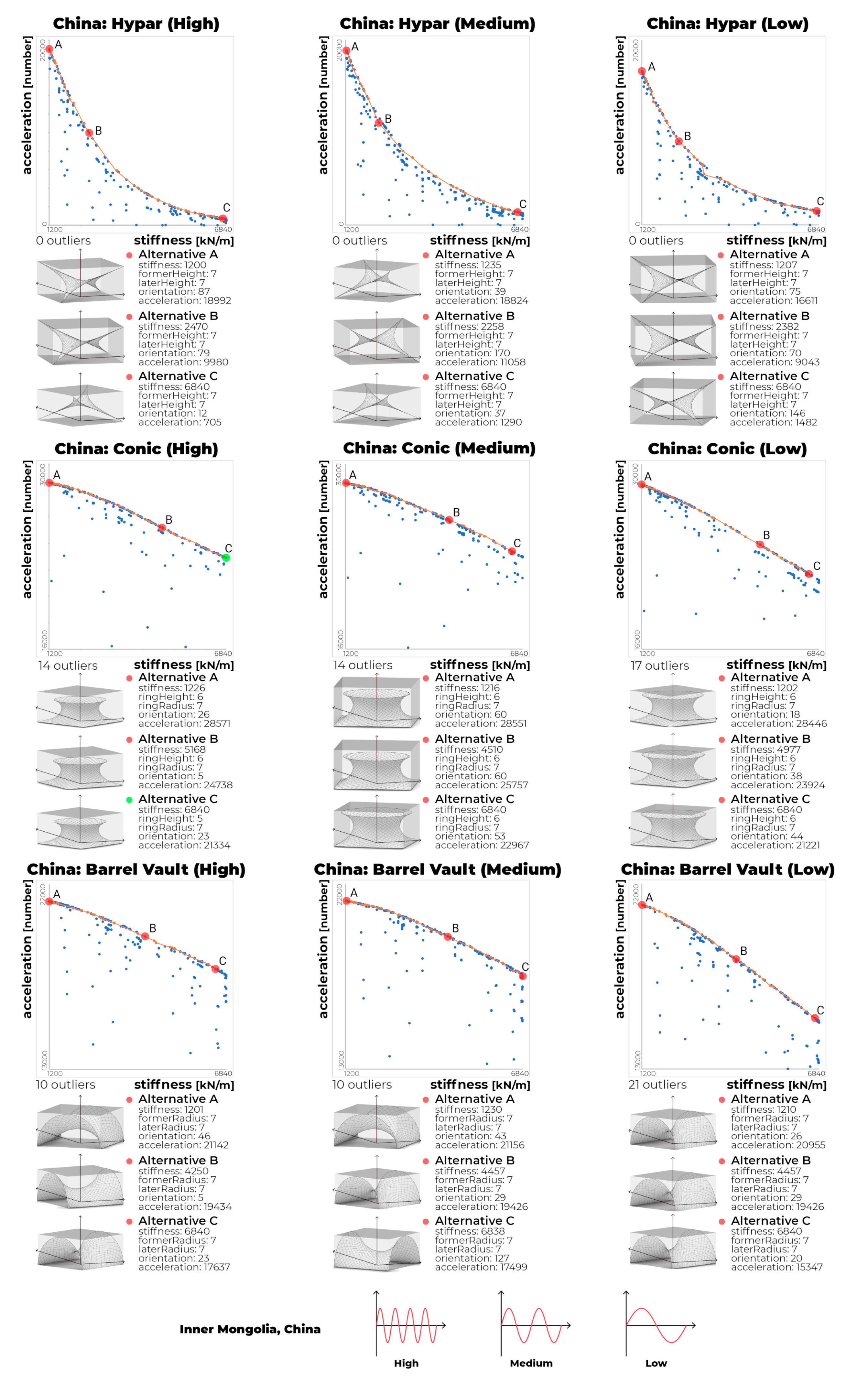
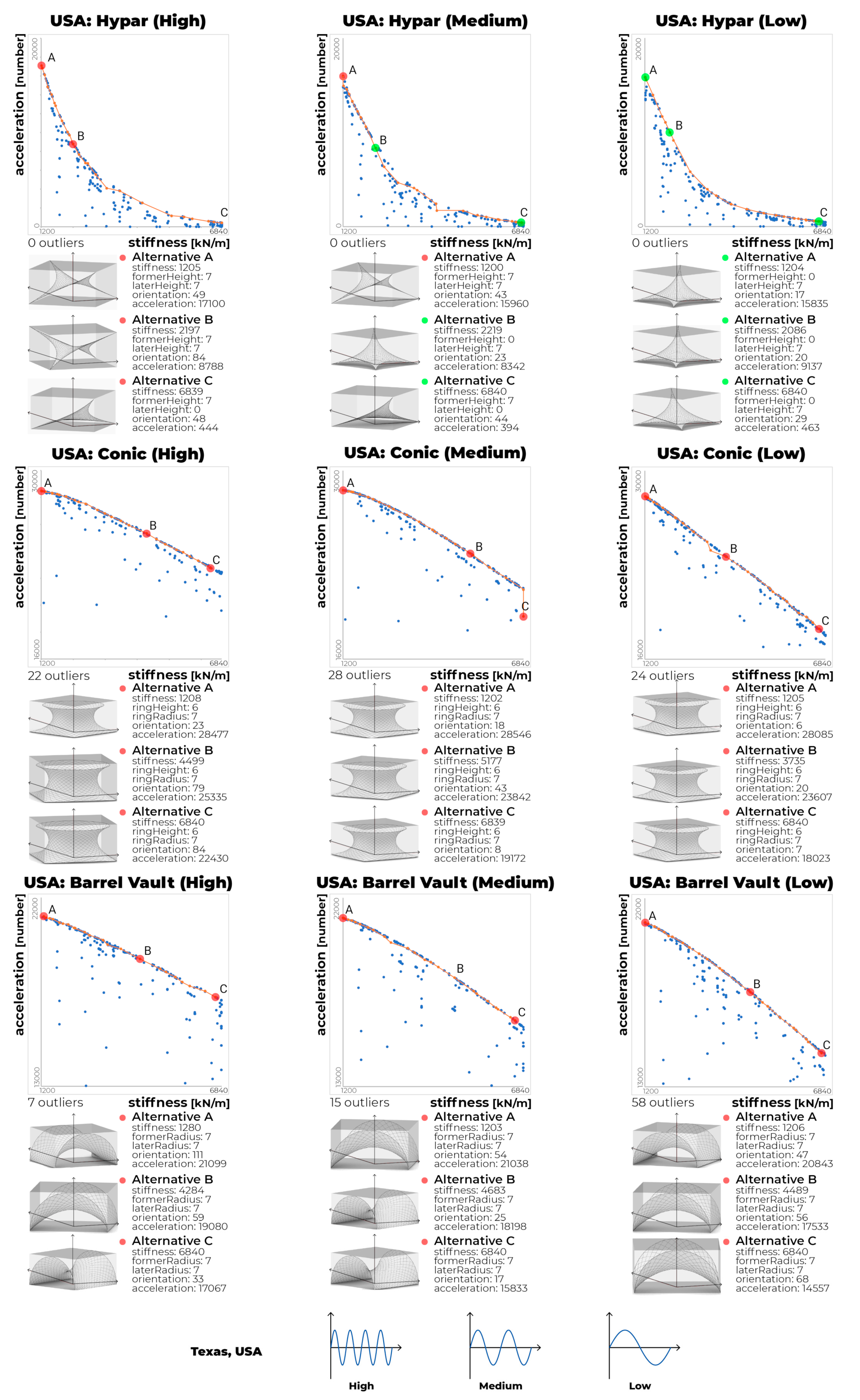
Figure 4 and
Figure 5 show the results of 18 multi-objective Pareto optimizations. Five optimization simulations were conducted, one at a time, on a total of two computers over 2 d, taking a total of 4 d. The x-axis of the graph indicates the stiffness, and the y-axis indicates the acceleration. To unify the graph range between structures of the same type and improve the legibility of the graph, we removed outliers whose acceleration values were too low. The number of alternatives removed is shown at the bottom left of each graph. The polyline in each graph represents the 30th-generation Pareto-front solutions. The three highlighted points in the graphs represent two extremes and middle design alternatives, which were used to assess the optimization, and the 3D models of the three alternatives are presented at the bottom of each graph. As provided the most energy generation among the alternatives, and the
Cs provided the highest stability (
Figure 4 and
Figure 5). One that has its acceleration value closest to the average acceleration value of As and Cs was selected as B. For each representative alternative, detailed values are presented on the right side of the model. In all the graphs, an inverse relationship between the stiffness and acceleration is clearly observed. Similar to the previous study [
12], the stability and energy efficiency are inversely correlated, regardless of the wind environment. The optimal graph for the hypar shape was convex, and the rest of the graphs were straight-like concave. Thus, the graphs for the conic and barrel-vault shapes differ substantially from that for the hypar shape. Because of the convex shape, the hypar is significantly affected by the material stiffness on small stiffness values, and the amount of electricity generated decreases as the material becomes stiffer. In comparison, the conic and barrel-vault shapes are constantly affected by material stiffness, and even if the material is stiff, it is not significantly affected by the amount of electricity generated. The selected alternatives of
Figure 4 and
Figure 5 exhibit efficient geometric shapes that are hardly affected by the wind pattern. Among a total of 54 alternatives, regardless of location in Inner Mongolia or USA, the shape variable that ensures high energy efficiency appears. Thus, the selected alternatives have common shapes. Dominating shapes that showed commonalities on most optimized alternatives are the hypar with former and later heights of 7 m; the conic with ring radius of 6 m and ring height of 7 m; and the barrel vault with former and later y-radiuses of 7 m. The selected alternatives with dominating shape were marked with red dots in
Figure 4 and
Figure 5. On the other hand, only the hypar selected alternatives in Texas have an optimized shape different from the dominating shape. The non-dominant hypar comprises the former height of 7 m and the later height of 0 m or the opposite. It shows that the optimized shape may be different depending on the wind environment. The shape of selected alternatives in Texas or the dominating shapes have similarities in which the height/side length ratio of geometry is large. Since the wind blows horizontally in the simulation environment, alternatives of shapes with a large height/side length ratio appear to be dominating heavily. In conclusion, the dominating shapes in the five environments, except the USA hypar, have the highest energy harvesting in any stiffness or wind environment.
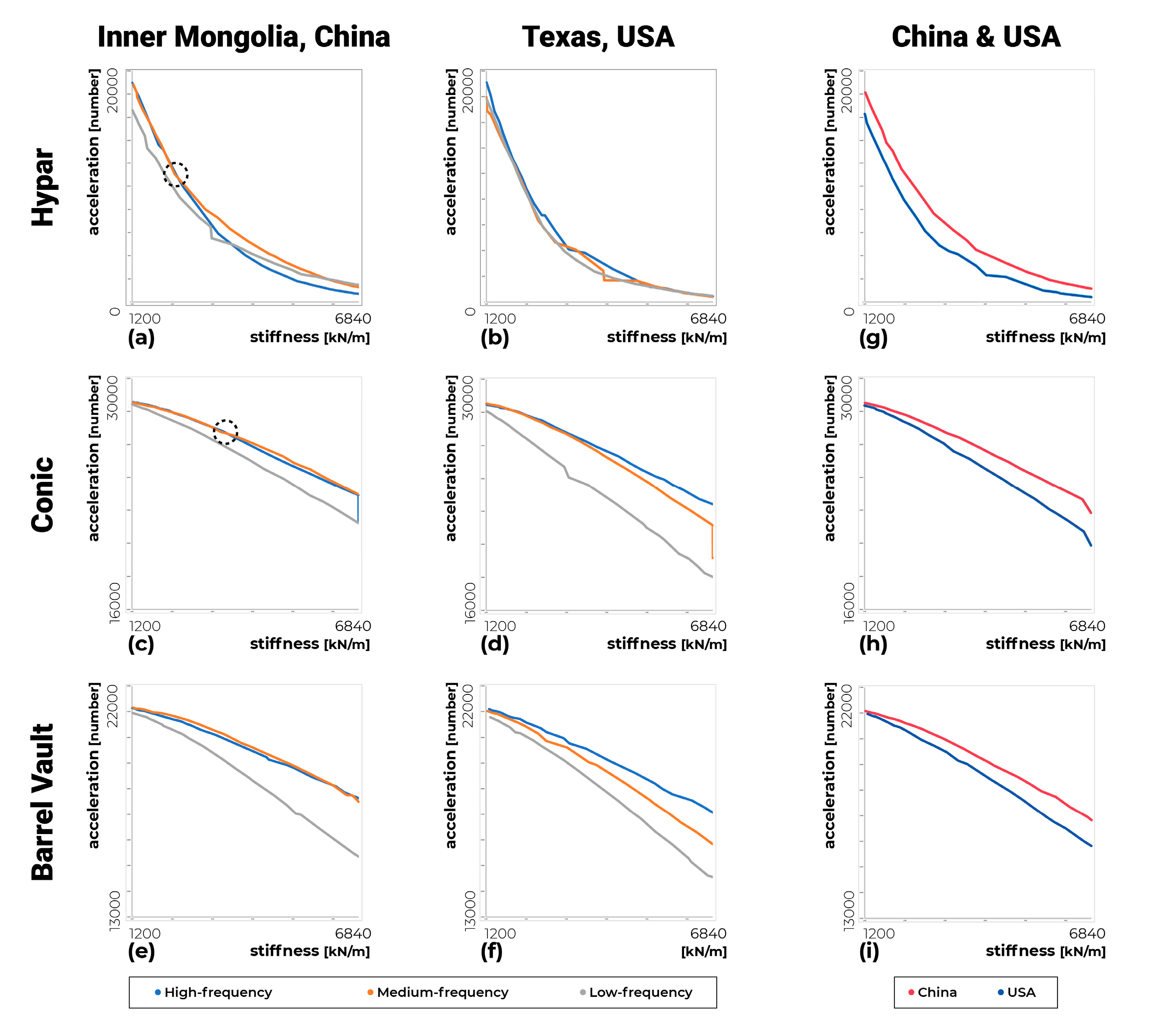
As shown in
Figure 6, the performance of the same TMA type in different environments was investigated. The results of the Pareto solutions of each experiment are presented, grouped by shape type and region. The performance of the TMAs in the same region and with the same shape type corresponding to the three wind patterns is visualized in
Figure 6a–f graphs.
Figure 6g–i graphs compares performance by region with the average acceleration value between Inner Mongolia and Texas. Inner Mongolia, which had a higher average wind speed, appeared to have a larger amount of electricity generated than Texas. In Texas, at a higher frequency, there was a higher probability for electricity to be generated. However, in Inner Mongolia, the electric generation was not proportional to the wind frequency. Moreover, the acceleration values of the low-frequency alternatives exceeded those of the high-frequency alternatives in
Figure 6a. In the Inner Mongolia graphs, the acceleration values of the medium-frequency alternatives overtook the high-frequency alternatives at stiffness values of 1900 (hypar), 2300 (conic), and the whole (barrel vault), respectively. The results for China’s medium-frequency alternatives indicate that the wind pattern plays an important role in the energy-harvesting performance of the TMA. As mentioned in
Section 3.2, the wind direction (WindVector) and wind strength (Amplitude) values changed every 10 iterations. The value of WindVector varied every 10 iterations according to the region (
Figure 1), regardless of the frequency, but the value of Amplitude varied every 10 iterations according to the frequency type (
Figure 2). The experimental results suggest that when the WindVector changed significantly, the high-frequency wind speed was low (close to zero), and the medium-frequency wind speed was high; thus, the acceleration was high. Importantly, the results indicate that a high wind frequency does not necessarily correspond to a high energy efficiency.
Table 2 shows the reduction rate from the largest acceleration value to the smallest acceleration value among the 30th generation results in
Figure 6. Since the reduction rate of hypar is much larger than those of the other two types, when designing hypars, it is recommended to determine the material stiffness as an extra consideration. The reduction rates of the conic and the barrel vault are about 20–30% thus, design focus on stability to prevent failure of the TMA seems more advantageous. The wind pattern affects the reduction rate without a specific rule. Design of a high energy efficiency TMA will need careful consideration of the wind pattern because it affects the acceleration value unexpectedly.
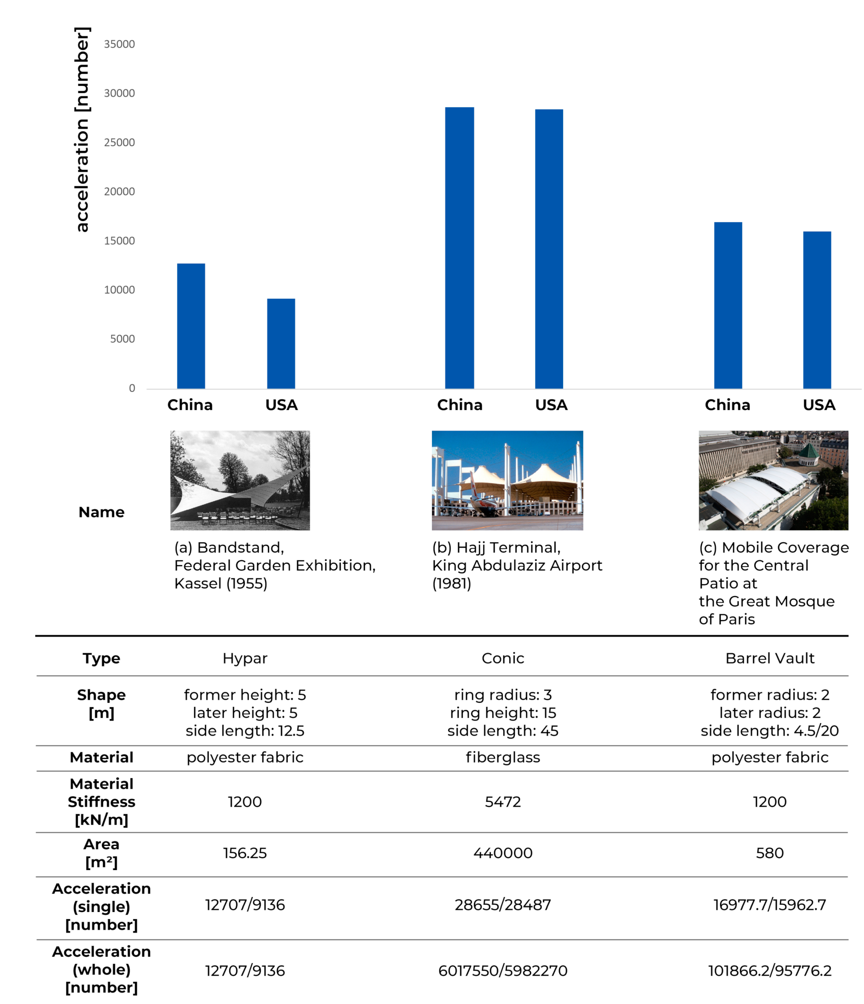
In
Figure 7, based on this study’s experimental results, virtual energy harvesting of TMAs was assumed, referring to existing TMAs. A total of three TMAs were determined for each shape type, and simulations were conducted to figure out their electric generation capacity. Information based on the TMAs in
Figure 7 was used to define the shapes, thus, polyester fabric provided the material stiffness of
Figure 7a,c and fiberglass provided the material stiffness of
Figure 7b. The three wind-frequencies of Inner Mongolia and Texas were used, and the orientation was fixed to 0. The simulation result presented an average of acceleration values of three different wind-frequencies in the two regions as bar charts. The covered surface of Arabia Jeddah Airport is extraordinarily large, composed of 10 modules consisting of 21 tent units. If the airport were an energy harvestable TMA, its sustainability would be a big help to run the facility and the building owner would gain advantages. It might have also been possible to collect the ambient energy from the other two TMAs if they were designed as energy harvestable TMAs and if they made use of wasted energy. TMA architects are recommended to consider an energy harvesting TMA to collect the wasted ambient energy.
To understand the energy harvesting TMA, shape, orientation, material, and vibration-based energy harvesting have been confirmed by examining Pareto optimal solutions with Pareto front graphs. Conic and barrel vault types had dominant shapes that performed maximum energy efficiency through the whole material stiffness range. The hypar type also had a dominant shape but two non-dominant shapes consisted of identical height/edge lengths with the dominant shape performed in Texas. The orientation did not attract much attention because it varied all in the optimization result. Material stiffness influenced the electric generation differently in hypar when compared to conic and barrel vault types. Not only a reduction rate but also the degree of decrease or increase showed a similar pattern between conic and barrel vault. Low material stiffness is significantly essential, especially for the hypar, to maintain high energy efficiency.
5. Conclusions
In this study, the previous research of Maeng and Hyun [
12] was extended, and the TMA was optimized with two objectives—power generation and stability—for the environments of Inner Mongolia and Texas. A total of 18 Pareto optimal graphs were visualized, and 54 selected Pareto-front solutions were proposed. When designing an energy-harvesting TMA, designers can determine appropriate tradeoffs through Pareto-optimal solutions and the correlation between the material stiffness and the electricity generation. Some designers may sacrifice energy efficiency to achieve the required stability whereas others may select the Pareto solution with the largest amount of electricity generation for enhancing the sustainability. Regardless of the design objectives, TMA designers can consider green energy in the future, and the TMA can be useful to designers considering green energy buildings. The novelty of this paper stems from the regional wind pattern and the TMA orientation. TMA designers have focused on TMA designs that do not fail and the elastic constants were mainly used as assistance for biaxial data and stress-strain data. Unlike the present, when designers put values in the feasible zone and end the investigation, after an introduction to a new research area—energy harvestable TMA—designers could adjust the elastic constants—push the parameters to the limit just before failure to maximize the electric generation. An important finding is that high wind frequency does not ensure high energy efficiency. Frequent changes in the wind speed do not necessarily improve the vibration of the harvesters on the membrane. Therefore, a detailed wind-pattern analysis is needed to construct an efficient energy-harvesting TMA. To the best of our knowledge, this was the first study in which the TMA was optimized with regard to the building shape, orientation, material, and vibration-based energy harvesting. According to the experimental results, it is recommended that designers select materials with a high stiffness with consideration of the effect of stability on efficiency when choosing materials for conic or barrel-vault structures. However, for hypar structures, it is recommended that designers choose materials according to the energy efficiency. The shapes of the Pareto front solutions did not differ significantly between Texas and Inner Mongolia, but in the case of the hypar shape, the design variable range is wider due to differences in optimized shapes between the two regions. For the conic and barrel-vault shapes, the specific shape suggested in the Pareto solution is expected to have the highest energy efficiency even in other wind environments. To overcome and supplement the limitations of computational simulation, an actual scale model of the TMA can be developed. Additionally, in this study, the Poisson’s ratios and shear moduli, which are used to evaluate the stability of TMAs, were neglected in order to focus on the material stiffness of each material type. The use of these properties together with the material stiffness (Young’s modulus) will enhance future simulations. Fluid–structure interaction programs that can consider the movements of the membrane due to wind will be useful for the development of a more sophisticated urban wind environment.
