Review

Attenuation Factors in Molecular Electronics: Some Theoretical Concepts

SPEC, CEA, CNRS, Université Paris-Saclay, CEA Saclay, 91191 Gif-sur-Yvette, CEDEX, France
Appl. Sci. 2020, 10(18), 6162; https://doi.org/10.3390/app10186162
Submission received: 30 July 2020 / Revised: 27 August 2020 / Accepted: 1 September 2020 / Published: 4 September 2020
(This article belongs to the Special Issue Molecular Electronics)

Abstract

:
Understanding the electronic transport mechanisms in molecular junctions is of paramount importance to design molecular devices and circuits. In particular, the role of the different junction components contributing to the current decay—namely the attenuation factor—is yet to be clarified. In this short review, we discuss the main theoretical approaches to tackle this question in the non-resonant tunneling regime. We illustrate our purpose through standard symmetric junctions and through recent studies on hybrid molecular junctions using graphene electrodes. In each case, we highlight the contribution from the anchoring groups, the molecular backbone and the electrodes, respectively. In this respect, we consider different anchoring groups and asymmetric junctions. In light of these results, we discuss some perspectives to describe accurately the attenuation factors in molecular electronics.

1. Introduction

One of the main goals of molecular electronics is to mimic standard electronic circuits using molecules instead of p-n junctions like components based on silicon [1]. To do so, the first property to achieve in a molecular junction is to favor and understand at the fundamental level the circulation of the electronic current through the molecule. The problem of the electronic conduction mechanism in a molecule connected to metallic electrodes is very complex, and the possibility of many different regimes has been well presented theoretically by Reed et al. [2,3]. In particular, according to the molecular length, different regimes are observed, which exhibit different dependences in voltage and temperature. Hence, in the frame of elastic transport (considering that inelastic interactions only occur in the electrodes), for big molecular chains (longer than 5 nm), the electronic transport lies in an activated regime, called hopping regime, which is thermally activated. Indeed, in this regime, the conductance evolution of the molecular junction can be written as G ~ exp(−EA/kBT), where EA represents the hopping activation energy, around 0.5 eV, kB is the Boltzmann constant and T the temperature [4]. With respect to the molecular length, the conductance decreases linearly, which is easily understandable since the electrons have to jump (hop) from one molecular site to the nearest neighbor one [5,6]. This behavior is characteristic of Ohm’s law, which we can observe at the macroscopic scale.
For smaller molecular chains, (i.e., below 5 nm) [7], the regime is not activated anymore and corresponds to the direct tunneling of the electrons through the molecular junction, provided that the applied voltage is lower than the characteristic electronic barrier of the system. In this case, there is no temperature dependence, and it is a reasonable approximation to say that the current varies linearly with the voltage at low bias. Indeed, the current–voltage relation is often non-linear for a significant range of voltages, before the molecular level is brought into alignment with the Fermi level of the electrodes. The transition between both regimes has been observed around 4 nm in conjugated polymers [8]. Note that, for larger voltages, this regime is generalized to the Fowler–Nordheim tunneling, where the current varies like the inverse of the voltage [9].
A fundamental problem in electronic transport in molecules lies in the length dependence of the conductance in the molecular junction. This dependence is reflected in the so-called attenuation factor, which is representative of the electronic current propagation in the molecular junction. Since a molecular junction is generally not metallic, the electronic conductance decreases as a function of the molecular length. Obviously, bearing in mind that the main application of molecular electronics is to design new devices for future electronics, one is interested in the lowest possible attenuation factor in order to increase the current in the molecular circuit. In the direct tunneling regime that we will particularly consider here, the conductance decays exponentially with respect to the molecular length, as we will detail in the next section. The main goal is therefore to reduce this exponential decrease as much as possible in order to optimize the electronic flow in the molecular circuit.
Hence, many experimental studies have been devoted to the determination of attenuation factors in different types of molecular junctions. In the meantime, theoretical methods have been developed to determine the electronic and transport properties of molecular junctions. The aim of this short review is not to describe extensively what has been done in the field, which would lead to an unreasonable amount of references, but more to discuss, in light of some representative systems, the progress and perspectives in theoretical methods to characterize the electronic transport in molecular junctions and to determine the attenuation factors.
In this respect, this review is organized as follows: in the first section, I will present a short state of the art of experimental determinations of attenuation factors in molecular junctions, and I will stress the most important results. Then, I will discuss the commonly used theoretical approaches, pointing out the corresponding strengths and weaknesses. In the fourth section, I will illustrate this discussion with the standard case of alkane-based molecular junctions, considering first the role of the anchoring groups in a symmetric junction with metallic electrodes and then by breaking this symmetry by using either different electrodes or different anchoring groups at each molecule sides. Obviously, since the anchoring groups are present in all the systems considered here, their influence will be analyzed in coordination with the different electrodes, molecular backbones and symmetry breakings. The underlying physical mechanisms will be addressed in light of these non-symmetric junctions. To complete this section, I will also discuss the role of the molecular backbone and its potential influence on the attenuation factor. Finally, I will summarize and draw some conclusions in the last section.

2. Some Attenuation Factors of Standard Molecular Junctions

In this review, we will consider specifically the non-resonant tunneling regime, which deals with small molecular lengths in the junction (typically below 5 nm [7]) and also low applied bias. In this case, the evolution of the conductance with respect to the molecular length can be written in the following form:
G = A exp (−βL),
where L is the molecular length, A is the pre-exponential factor representative of the contact resistance at the molecule–metal interface, and β is the attenuation factor [10]. This attenuation factor is representative of the current attenuation within the molecular junction, with respect to the molecular length. In order to redefine the context, the attenuation factor is zero for a pure metallic junction, as no attenuation occurs, whereas it is of the order of 25 nm−1 for the vacuum where the current is fully attenuated.
A standard example of attenuation factor measurement is alkane-based molecular junctions. Many studies have been devoted to this system, and the attenuation factor currently lies around 7–9 nm−1 [10,11,12]. It has to be noted that this value is strongly dependent on the chemical nature of the molecular wire, since substituting carbon by silicon to constitute what is called oligosilane chains reduces the attenuation factor to 3.9 nm−1 [13]. This effect is even more enhanced considering germanium-based molecular wire, to form a germane chain, leading to β ~ 3.6 nm−1 [14]. In this respect, we can speculate that going down the lines of the periodic table, i.e., increasing the atomic number of the chain constituents, would lead to an important reduction in the attenuation factor—in other words, a higher conductance, potentially related to the increasing number of electrons per atom. On the other hand, still considering non-conjugated molecular chains, the opposite behavior is found in siloxane chains, where the repetition unit is based on a Si-O dimer, with a very important attenuation factor of β ~ 12.3 nm−1 [15]—in other words, almost no conductance.
Beyond the chemical nature of the molecular chain elements, the nature of the molecular bonding plays an important role. For example, coming back to carbon elements, aromatic chains present reduced attenuation with respect to alkane chains, with β ~ 2.5 nm−1 [16]. Similarly, carotenoid polyenes present β of 2.2 nm−1 [17] and oligothiophenes have β between 2 and 3 nm−1 [18]. Consequently, one can deduce that the aromaticity of the molecular chain helps in reducing the attenuation factor; however, it is more or less always in the same range.
Besides the above, some more complex molecular systems also exhibit even lower attenuation factors, around 10 times lower than the polyenes discussed previously. For example, polymethine dyes, which are π-conjugated compounds with an odd number of carbons, have attenuation factor β ~ 0.4 nm−1 [19]. This is mainly attributed to greater electronic delocalization, in comparison to standard polyenes, enhanced by a smaller degree of bond order alternation. However, this behavior seems to be limited by the molecular length, leading to a more resistive junction for long molecular chains. In addition, the more exotic case of porphyrin polymers is very interesting. Indeed, when considering oligo-porphyrin molecular junctions, based on Zn porphyrins with pyridine ligands, one can observe a similar reduced attenuation factor β ~ 0.4 nm−1 [20]. Actually, it seems that the molecular conductance has a strong temperature dependence and a weak length dependence, even though it does not correspond to the hopping mechanism described in the introduction. It is rather consistent with phase-coherent tunneling through the whole molecular junction. Even more surprising is the result obtained by Leary et al., who have studied molecular chains of fused porphyrins [21]. Namely, in the considered porphyrin oligomers, the monomers connect directly with their nearest neighbor through the porphyrin cycle. In this case, contrary to the previous cases discussed here, the conductance increases with the distance, by more than a factor of 10, when a small bias (~0.7 V) is applied to the junction. This exceptional behavior is due to the evolution of the HOMO-LUMO gap that rapidly decreases with the molecular length, which compensates for the increased tunneling distance. Finally, the last example to be cited with respect to low attenuation factors is the work conducted by Brooke et al., who show a structural control on the electronic transport resonance in HS(CH2)n[1,4 −C6H4](CH2)nSH (n = 1, 3, 4, 6) metal–molecule–metal junctions, leading to very small attenuation factors [22]. This work offers very promising perspectives in gating the transport resonance in order to modulate the molecular junction behavior.
In this discussion, we have mainly considered the case of single molecule junctions. An interesting question that arises is this: what happens if we consider not only a single molecule junction but also a large molecular area? In this case, several experiments have found that the attenuation factor β mainly remains the same, and only the prefactor of the conductance is modified, as for molecular junctions based on biphenyl, nitrophenyl, ethynyl benzene, anthraquinone, etc., where one can observe attenuation factors around 2.7 nm−1 [23] (see Figure 1).
As an important consequence, these results show that the study of single molecule junctions is not only important at the fundamental level. The understanding of the transport mechanism at the single molecule level and, in particular, the determination of the attenuation factor may be extrapolated to large molecular areas, which are currently used in molecular electronics devices. Another important aspect that can be stressed is that, below 5 nm, it seems that there is no significant difference in the attenuation factor with respect to the molecular backbone of the aromatic molecules considered in the junction. This might be attributed to the relative positions of the molecular electronic levels, which remain constantly pinned near the Fermi level at around 1.3 eV [23,24]. We will see in the next sections that this position of the molecular levels is an important parameter to determine the attenuation factor. However, it has to be noted also that most of these experimental results have been obtained using molecular junctions in symmetric configurations, namely with the same electrode at each side of the junction (most of the time, metallic electrodes made of noble metals) and similar anchoring groups. Very few studies have considered non-symmetric junctions—for example, with different anchoring groups at each molecular end—which might have an influence on the position of the molecular levels and yield other kinds of information about the transport mechanism [25,26]. In addition, as we will detail later, some recent experiments have started to use different electrodes at each end as well as non-metallic electrodes. Obviously, the question that arises is this: what is the fundamental element in a molecular junction that determines the attenuation factor? Is it the chemical nature of the molecular backbone? Is it the anchoring groups? Is it the electrode or the coupling to the electrode? Alternatively, is it a mix of all these aspects? To answer these questions, theoretical modeling of the molecular junction and of the electronic transport through the junction is of paramount importance. In particular, it should help to discriminate these different contributions. In the next section, we will consider the most common theoretical approaches to characterize the electronic transport in a molecular junction and to determine the attenuation factor.

3. Theoretical Approaches

In this section, we will discuss the most common theoretical approaches used to determine the electronic transport and in particular the attenuation factor in a molecular junction. An extensive review of electronic transport calculations using ab initio and density functional theory (DFT) based methods and Green functions can be found in [27]. Unfortunately, a direct relationship with the attenuation factor and overall a deep interpretation is not necessarily straightforward to deduce from these calculations. The objective here is to present the main contribution from the different parts of the molecular junctions that are characterized theoretically in each approach.
Hence, the most common description of the electronic current in a molecular junction has been shown by Simmons [1,28], considering the tunnel effect between metallic electrodes and a thin insulating film. In this respect, the current and the electronic conductance follow an exponential decay, as proposed in Equation (1), where the attenuation factor β can be expressed as β ( 2 m φ / , with m the mass of the electron, the reduced Planck constant and where φ represents the electronic potential barrier of the system. In a molecular junction, this barrier is nothing other than the energy difference between the closest (non-resonant) molecular level to the Fermi level of the electrode and the Fermi level [1,10]. Namely, if we consider electron transport, β will depend on the ELUMO–EFermi difference, whereas, if we consider hole transport, β will depend on the EFermi–EHOMO (ELUMO, EHOMO and EFermi being, respectively, the energy position of the LUMO, HOMO and Fermi level of the system). The immediate consequence of this interface property is that, in principle, beyond the nature of the molecular backbone, one could modulate the attenuation factor by changing the specific anchoring groups forming the bond between the molecule and the electrode. Indeed, the position of the molecular levels with respect to the Fermi level is mainly influenced by the anchoring groups used to connect the molecule to the electrodes. This aspect will be detailed later when considering properly the influence of the anchoring groups in well-established examples. However, this heuristic model is inspired by scanning tunneling microscope (STM) experiments, or the standard evolution of a wave function through a potential barrier in quantum mechanics, and represents the simplest expression of the Simmons model [28], currently used in molecular electronics to describe conductance attenuation in molecular systems. It works rather well for molecular junctions where the levels are close to the Fermi level but requires more ingredients when this is not the case.
Other more sophisticated models highlight the role of the molecular backbones without taking into account the interfaces between the molecule and the electrode. For example, from an atomistic point of view, the conductance of the molecular wire can be understood using a simple tight-binding model, with N sites of energy ε1, ε2… εN coupled through hoppings t1,2, t2,3, …. tN-1,N and bridging the two electrodes [29] (see Figure 2).
Notice that these energy sites are independent of the coupling at the interfaces, which automatically eliminates the role of the anchoring groups. Moreover, we can consider that all these energies are identical, namely to ε0, and the same for the hoppings, which are all equal to t. In this approach, the attenuation factor can be expressed as:
β(E) = (2/a) ln |(E − ε0)/t|,
where a measures the segment size, for a total molecular length of Na [1]. Considering the energy E as the Fermi level, and average values of |(E − ε0)/t| = 10 and a = 5 Å, this expression gives typical values of β of around 9 nm−1, independently of the anchoring groups or the electrodes. Note that a similar result can be deduced from the dispersion relation of an infinite linear chain:
2t cosh(κa) = EFermi − ε0,
with κ = β/2, (EFermi − ε0)/t >> 1, and where the hyperbolic cosine stands for the exponential behavior at each side of the molecular chain where the electronic wavefunction tunnels from or to the electrode. In other words, this approach is also a generalization of the Simmons model. However, here, the energy difference EFermi−ε0 corresponds to the potential barrier of an infinite molecular chain without anchoring groups or electrodes, namely ε0 being an orbital of the infinite molecular backbone and not, for example, the HOMO level of the junction.
Finally, the last important model lies in the determination of the attenuation factor through a complex bandstructure calculation [30,31]. Similarly to what happens in solid state physics, an infinite molecular chain (analog to an infinite crystal) is considered and its bandstructure is calculated. Real wavevectors correspond to the usual molecular spectrum of the junction.
The attenuation factor is determined from the calculation of evanescent states of the electronic wavefunction inside the molecule, namely the electronic states corresponding to complex wavevectors. These evanescent states, which correspond to the Schockley surface states in solid crystals [32], correspond to the different potential conduction channels of the molecular junction, originating from the different orbital hybridizations. Obviously, among all these different channels, the current will follow the channel with the lowest attenuation factor, similarly to the macroscopic behavior. Therefore, the value of the attenuation factor can be read on the complex bandstructure for the evanescent state with the smallest extension in the gap, as represented in Figure 3. This approach also leads to attenuation factors around 8 nm−1 for alkane chains. Notice that an interesting mathematical derivation establishes a link between this result and a square root variation for the attenuation factor similar to the one of the Simmons model. However, this expression is valid again only for the infinite molecule and not for the one whose HOMO and LUMO levels are determined by the coupling at the interface.
To summarize the different theoretical approaches presented in this section, we can observe that each approach stresses a specific contribution. Hence, the model considers either the anchoring groups/electrodes (namely the coupling of the molecule at the interface) through the relative position of the molecular levels with respect to the Fermi level or the molecular backbone (namely the chemical nature of the molecular chain), in a rather exclusive manner. Consequently, it remains difficult to determine accurately and for all kinds of molecular junctions the corresponding attenuation factor. As such, a universal model does not seem to exist yet. Therefore, the debate remains open regarding whether the attenuation factor is determined by interface effects or only by the molecular backbone or by a combination of both. A large experimental consensus seems however to be established in favor of a major influence of the molecular backbone. As a remark, we can stress nevertheless that all of these theoretical studies (as already discussed in the previous section for most of the experimental studies) have only considered symmetric cases, where electrodes and anchoring groups at each side were similar. The study of a non-symmetric case through these models would be of high interest to test their range of applicability.
In the next section, we will illustrate these different models with standard test cases, namely alkane molecules sandwiched between metallic electrodes, and we will investigate the respective roles of the electrodes, the anchoring groups and the molecular backbone, by investigating asymmetries in the junctions.

4. A Test Case: Alkane Chains

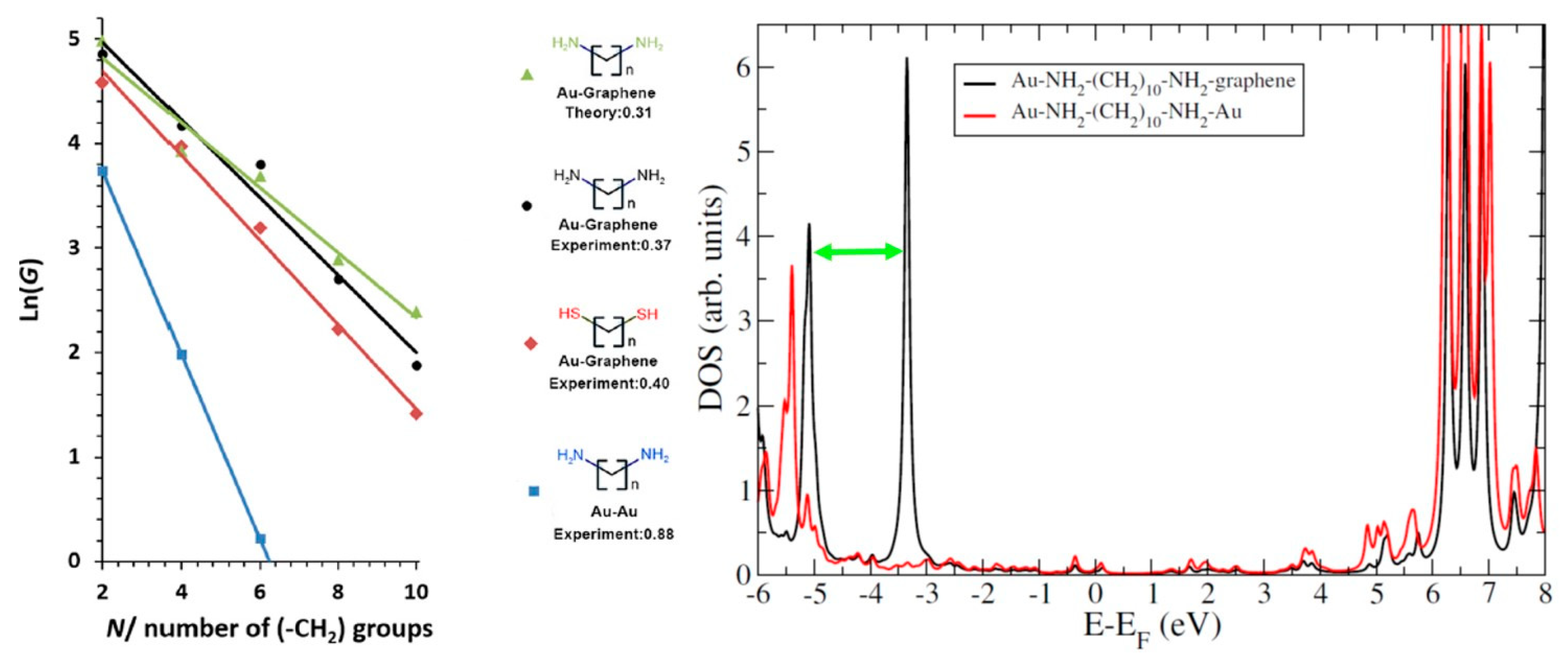
4.1. Role of the Anchoring Groups: Symmetric Junctions

Alkane polymers probably constitute the most common and the simplest molecular chains that have been studied in molecular electronics. Indeed, from their simple chemical nature, their easy availability and ability to connect to different chemical groups or metals and despite their very large gap, which would in principle reduce the conductance, it represents a toy model for electrical conduction in molecular systems. Hence, it is no surprise that this system has been measured in numerous works using different metallic electrodes (mainly noble metals Au, Ag, Cu) and different anchoring groups. Here, we briefly present the well-documented results in the literature on symmetric alkane-based molecular junctions, before exploring further the underlying physical mechanisms through the study of hybrid junctions. For example, anchoring groups like thiol (-SH) [33], amine (-NH2) [34], carboxylic acid (-COOH) [35], isocyanide (-NC) [36], methyl sulfide (-SMe) [37], etc., have been studied extensively. What is particularly interesting is the comparison of the measured attenuation factors for several junctions with different anchoring groups. For example, Chen et al. [38] performed such a comparison between thiol, amine and carboxylic acid anchoring groups. The first important difference in the respective electronic properties of these junctions lies in the contact resistance, which is inversely related to the prefactor A in Equation (1). Indeed, the contact resistance is smaller for thiol, bigger for amine and even bigger for carboxylic acid, which yields overall conductance higher for thiol than for amine and then higher for amine than for carboxylic acid. This is due obviously to the different kinds of electronic coupling at the interface, namely of covalent nature for the thiol, much weaker for the amine and related to a deprotonation process of the carboxylic acid to contact the electrode. In this respect, geometries at the interfaces are also affected and the involved symmetries are different, as we will see in more detail later. In addition, the electronic properties seem to be rather different, since the HOMO level is located at around 2.0 eV from the Fermi level in the thiol case, 5.5 eV for the amine case and 1.1 eV in the carboxylic acid case. These differences in HOMO level positions are attributed to different symmetry couplings at the interfaces, as will be discussed in the next section. However, despite these important differences, the attenuation factors seem to remain rather similar for the three junctions, around 0.8–0.9 per C atom (or –CH2 unit). Considering such similarities in the attenuation factors for different anchoring groups, one can wonder what the real impact of the anchoring groups on the attenuation factor is. From these first results, the only incidence that we can deduce is a variation in the contact resistance and consequently a variation in the overall conductance. In the next section, we will consider the role of the electrode, using different anchoring groups, in the electronic transport in molecular junctions. The main idea is to compare the influence of the anchoring groups with the same or different electrodes.

4.2. Role of the Electrodes: Hybrid Junctions Using a Graphene Electrode

Most of the conductance measurements in molecular electronics have used metallic electrodes and, in particular, noble metals, either using mechanically controlled break junctions (MCBJ) [39], scanning tunneling microscopy (STM) [40], conductive probe atomic force microscopy (CP-AFM) [41] or also the STM-based I(s) method developed by Nichols et al. [42]. Nevertheless, an important number of recent works have been devoted to the use of carbon electrodes or even graphene substrates [43,44]. In this respect, we will discuss here the attenuation factors measured experimentally and determined theoretically on hybrid molecular junctions with a gold electrode at one molecular end and a graphene electrode at the other. We will also consider the role of different anchoring groups using this graphene electrode.
First, we start by considering alkanedithiol molecules of different lengths, probed experimentally using the I(s) method and modeled using DFT and electronic transport calculations to interpret the obtained results [45]. An atomic model of the system is represented in the left part of Figure 4 for a butanedithiol sandwiched between a gold and a graphene electrode, forming a hybrid metal/molecule/graphene junction. The conductance has been measured for different molecular lengths between 2 and 12 –CH2 groups, allowing us to deduce the length dependence of the conductance. In this respect, the use of a graphene electrode does not affect the exponential conductance decay. In parallel, electronic transmission spectra and conductance have been calculated after DFT structural optimization of the junctions and density of states calculations. In addition, the contact resistance has been determined to be significantly larger than what is obtained for a standard symmetric junction with two gold electrodes. This is due to the weak coupling (of van der Waals nature) at the graphene–molecule interface.
The length evolution of the experimental and theoretical conductance is represented on the right part of Figure 4.
As a result, the attenuation factor for this hybrid junction is approximately half of the one obtained for its symmetric metal–molecule–metal counterpart. Namely, the attenuation factor now lies at around 0.4 per carbon atom. Hence, even though the contact resistance is quite high for the hybrid junction due to the weakly coupled interface with graphene, for molecules longer than ~1 nm, the metal–molecule–graphene junction turns to be more conductive than the standard metal–molecule–metal one. Moreover, for similar molecular lengths, the hybrid junction is also longer than the standard one, due to the van der Waals contact which requires a 3 Å distance between the molecule and graphene. Therefore, the question arises: how can such unusual behavior occur? We will try to understand it in the frame of the Simmons model, the most common theoretical approach to determine an attenuation factor that we have discussed in Section 3. Hence, the electronic behavior can be explained as follows by the different couplings at the electrode–molecule interfaces and the different molecular level alignments. When a thiol-terminated alkane is adsorbed on a gold surface, due to the strong interface electrostatic dipole, there is an important charge transfer, which partially depopulates the molecule and moves the HOMO level toward the Fermi level of the surface. If the same molecule is contacted between two gold electrodes, there is an interface dipole at each molecular extremity, in opposite directions, leading to a cancellation of the two dipoles. Then, the HOMO level remains far from the Fermi level, at around 2 eV, as discussed previously, yielding an important electronic barrier that is reflected in a high attenuation factor (β ~ 8.6 nm-1 or 0.8 per C atom [1,11]). Note that Brooke et al. have also studied the case of symmetric junctions, where it was argued that dipoles in symmetric junctions can result in the HOMO level being dragged down in energy [22]. If the second electrode is now a graphene plane, the interface dipole at the graphene side ruled by van der Waals interaction is much weaker than the one at the gold side, which is not cancelled in this situation. This results in an important charge transfer at the gold–molecule interface and a shift of the HOMO level toward the Fermi level. Consequently, the energy difference EFermi–EHOMO is reduced to 0.4 eV, which reduces considerably the attenuation factor, to 0.4 per C atom, as observed experimentally. In this case, as we can see, the simple Simmons model is perfectly able to describe the electronic behavior of the junction. Moreover, we have observed that the use of a graphene electrode at one extremity breaks the electrostatic symmetry of the system, leading to a reduced attenuation factor for thiol groups, as compared to the same junction and two gold electrodes.
Now, in order to extend the comparison to symmetric junctions, and to probe the theoretical model used for the thiol case, we will consider another hybrid junction with different anchoring groups, namely amine groups [46]. The same procedure has been applied here with I(s) measurements and DFT based electronic transport calculations. The corresponding results are presented in Figure 5. First, we consider the evolution of the conductance as a function of the molecular length, in a logarithmic scale. Similarly to the case of the thiol Au–graphene junction, an attenuation factor of 0.4 per C atom is also found in the amine case. This behavior is consistent with what happens with Au–Au junctions, as we have seen in the previous subsection. Indeed, for all the anchoring groups, the attenuation factor remains practically the same. Here, the introduction of a graphene electrode seems to result in a similar effect, but it is reduced to around half its value with respect to Au–Au junctions. What is more surprising here is the direct comparison of the conductance with the Au–Au junction and the same amine groups. Indeed, while, for the thiol case, we observed greater conductance above a certain molecular length due to the reduced attenuation factor, we can observe for the amine group a more important conductance independently of the molecular length is, as shown in Figure 5. Even more surprisingly, while, for the Au–Au junction, the thiol case presents higher conductance than the amine one (due to better contact and lower contact resistance), in the Au–graphene junction, the amine case presents higher conductance than the thiol one.
In order to understand this particular behavior, we have calculated the density of states (DOS) for the alkane-based junction with amine anchoring groups, using Au–Au or Au–graphene electrodes. The result is represented in the right part of Figure 5.
The calculated DOS allows us to determine the position of the HOMO level (which is the closest level to the Fermi level and therefore the conductive one in the junction, as for the thiol junction), so that we can apply the Simmons model used previously to determine the attenuation factor and the overall conductance. However, the calculated DOS indicates here a HOMO level located not around 0.4 eV below the Fermi level but 3.5 eV below the Fermi level for the amine anchoring group. As a consequence, the use of such a big potential barrier in the Simmons model would necessarily lead to a huge attenuation factor, which is not in agreement with the experimental observations. Therefore, this simple example highlights some limitations of the models presented in Section 3. Indeed, other models based on complex bandstructure calculations would not help either in determining correctly the attenuation factor, as electrode asymmetry cannot be taken into account. Note that the determination of the attenuation factor for the symmetric Au–Au junction is complicated as well, since, in that case, the energy barrier is about 5.5 eV, which does not fit into the Simmons model either. From this system, we can deduce that there is no universal model to calculate accurately the attenuation factors in molecular junctions. Hence, the Simmons model can be used only for specific ranges of electronic potential barriers, and the other models seem to be valid only for symmetric junctions, without properly considering the influence of the anchoring groups or the electrodes.
In [46], this problem has been solved by considering that, between the Au–Au and the Au–graphene amine junctions, the HOMO level has been relocated from the same amount as in the Au–Au and the Au–graphene thiol junctions, namely around 2 eV (as indicated by the green arrow on Figure 5). Since the attenuation factors are the same for both anchoring groups in Au–Au junctions, it can be deduced that they should be the same for the Au–graphene junctions. The underlying reason is the fact that the coupling to the electrode and the molecular conduction are different for thiol and amine anchoring groups. The thiol groups connect very well to the electrodes, as of π symmetry, which explains the small electronic barrier, whereas the amine groups connect poorly to the electrodes, as of σ symmetry. Conversely, the thiol groups connect poorly to the alkane molecular backbone, yielding low intramolecular electronic propagation, whereas the amine groups connect much better, which increases the intramolecular propagation. One effect compensating the other, both anchoring groups lead to the same attenuation factor, mainly depending on the electrodes. This balance between coupling to the molecular backbone, leading to a good intramolecular conductance, and coupling to the electrode, which reduces the interface potential energy barrier, also explains the similar attenuation factors for different anchoring groups in alkane-based symmetric junctions between gold electrodes.
One last point has to be clarified regarding the overall conductance of the amine junction, and the explanation is found again in the DOS calculation. Indeed, the HOMO level is different in the case of Au–graphene electrodes, due to a level splitting with respect to the Au–Au junction. Indeed, the introduction of the graphene electrode breaks the symmetry of the molecular junction (this effect was also observed for the thiol junction, where the symmetry breaking was seen in the non-compensation of the electric dipoles) and splits the original HOMO level, leading to a reduced molecular gap (by about 2 eV). Consequently, since the overall conductance depends on the self-energies that couple the molecule to the electrodes, and these self-energies vary as the inverse of the molecular gap, this important reduction of the gap leads to a much higher molecular conductance. This is why the Au–graphene alkanediamine junction presents more important conductance than its Au–Au counterpart but also than the alkanedithiol junction, where the introduction of the graphene electrode shifts the molecular levels without any gap reduction.

4.3. The Case of Platinum–Graphene Hybrid Junctions

In the previous subsection, we have considered hybrid Au–graphene electrodes for two different anchoring groups in alkane-based molecular junctions and we have observed an important reduction in the attenuation factor. Here, we will observe the effect of a change in the metallic electrode by substituting the gold electrode with a platinum one. As a matter of comparison, we consider again the alkanedithiol molecular junction, following the same experimental and theoretical procedure [47]. Similarly to the Au–graphene alkanedithiol molecular junction, the conductance presents an exponential decay, still within the framework of the non-resonant tunneling. The corresponding attenuation factor is slightly lower, around 0.3 per C atom, which is attributed mainly to the difference in work function between gold and platinum. It has to be noticed that this system is again very well modeled through the Simmons approach, because of the strong coupling to the electrode and the reduced electronic potential barrier.
Moreover, we can deduce from this result, combined with the results obtained on Au–graphene junctions, that the reduction of the attenuation factor is caused by the symmetry breaking of the graphene introduction in the system. This is not related to the nature of metallic electrode, but rather to the difference of interaction strength at each electrode interface. Indeed, the metallic electrode is coupled covalently to the molecule through the anchoring group, while the graphene electrode is coupled in a much weaker manner through van der Waals interaction. This is particularly true in the case of the thiol anchoring group, which deprotonates at the gold interface, leading to a –S radical (thiolate) that is very reactive with the gold electrode, whereas it remains in the thiol form –SH at the graphene interface, leading to van der Waals contact. Consequently, this is the interaction symmetry breaking at each molecular end, covalent/van der Waals, which leads to the important decrease in the attenuation factor and the increase in the molecular conductance. In this respect, one can anticipate that a molecule weakly coupled to two graphene electrodes through van der Waals interaction would probably present a similar attenuation factor as the one obtained for symmetric Au–Au junctions. As a remark, a similar junction has been studied using a graphitic tip for the I(s) measurements and the usual graphene electrode. The resulting attenuation factor was found to be very similar to the one of the Au–graphene junction, around 0.4 per C atom. This was due again to a coupling difference, since the graphitic tip was very reactive in this situation and coupled covalently to the molecule, whereas the graphene counter electrode coupled weakly to the molecule [48].

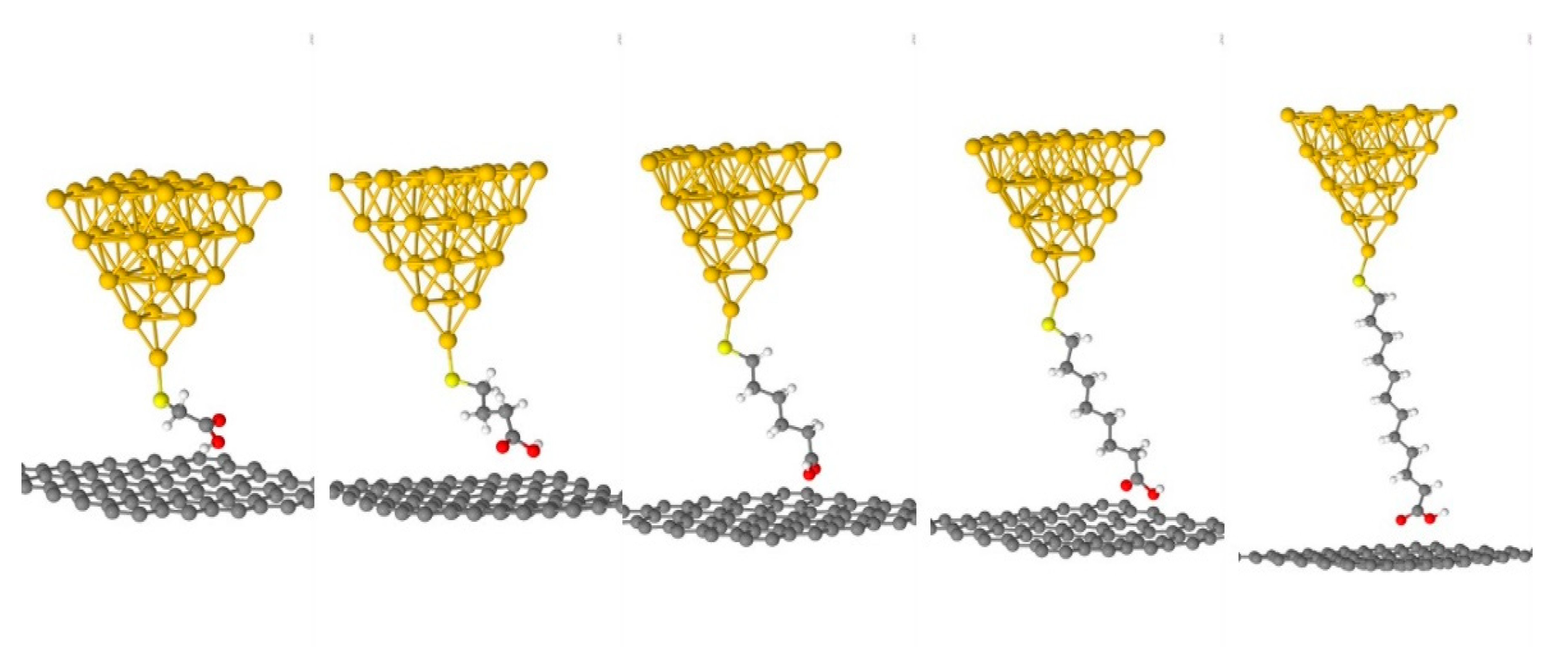
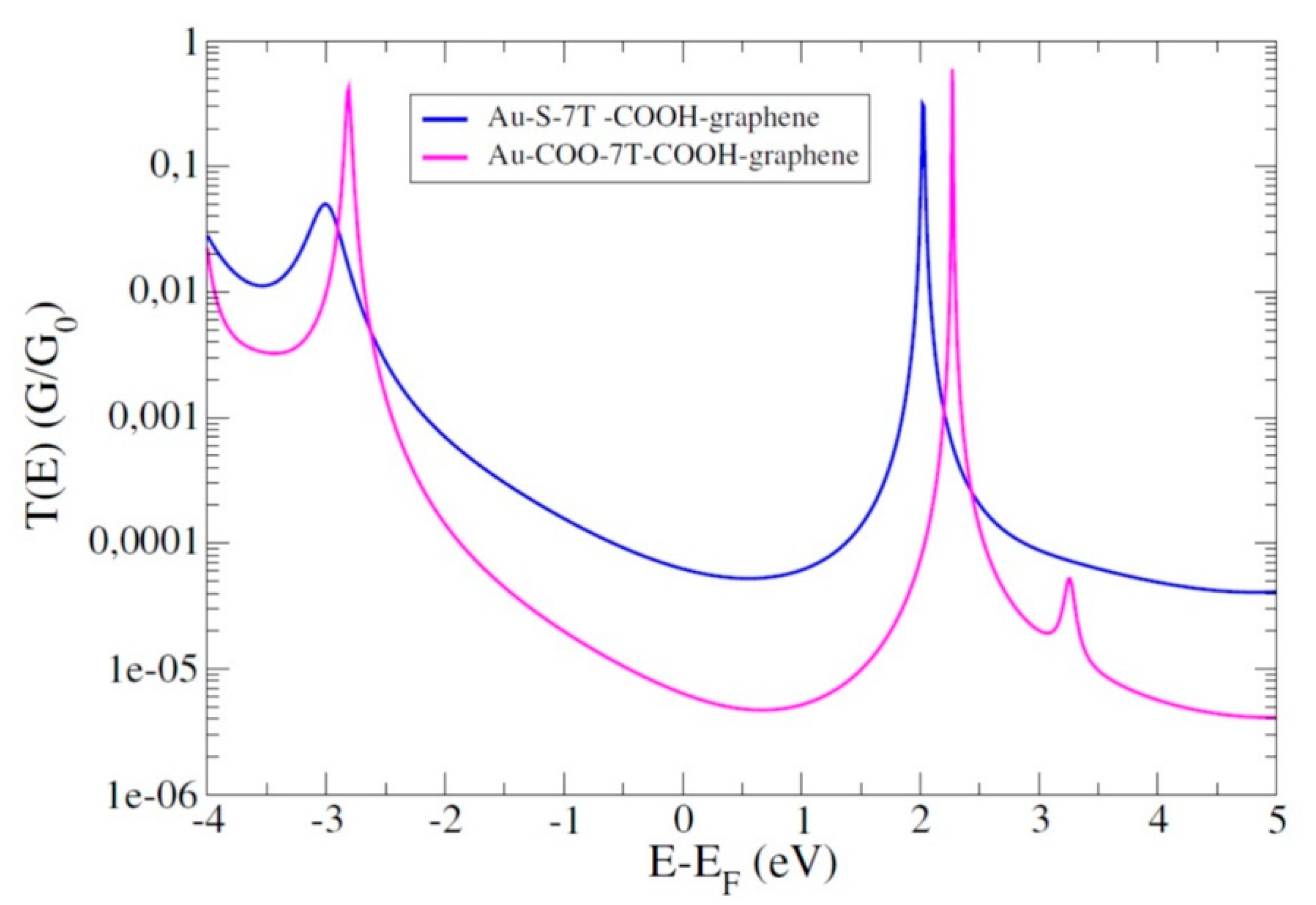
4.4. Role of the Anchoring Groups: Asymmetric Junctions

As we know now, symmetry effects are very important in electronic transport in molecular junctions. In particular, we have seen that it has a strong influence on the attenuation factor. For this reason, it is interesting also to see what would be the influence of considering different anchoring groups at each molecular side to connect the electrodes to the molecules. In this respect, we highlight here the interesting case of hybrid Au–S–alkane–COOH–graphene molecular junctions, where thiol and carboxylic acid groups have been used at each extremity of the junction with gold and graphene electrodes [49]. An atomic representation of the molecular junctions studied here is represented in Figure 6.
Obviously, from the theoretical considerations discussed above, there was no valid approach until now that was able to describe accurately such an asymmetric junction. Moreover, this type of junction has also been studied previously using Au–Au electrodes. As a reminder, the attenuation factor of junctions using only thiol or only carboxylic acid as anchoring groups are very similar, around 0.8–0.9 per C atom. Then, the corresponding attenuation factor for an asymmetric junction using different anchoring groups was found to be of the same magnitude, so without important change with respect to the symmetric junctions [25]. When considering junctions with Au–graphene electrodes, the situation is slightly different. Indeed, for a symmetric junction with carboxylic acid at both ends, the attenuation factor is around 0.7 per carbon atom, probably due to the low coupling of the carboxylic acid to the electrodes, which does not make a lot of difference in the situation of two gold electrodes. However, the situation is slightly different in the Au–graphene case, where the attenuation factor is around 0.4 per carbon atom, namely the same value as that found previously for thiol and amine groups in Au–graphene junctions. Interestingly, the electronic behavior is rather different. In thiol overall, but also in amine molecular junctions, the electronic transport is achieved through the HOMO level which is the closest level to the Fermi level. Here, as shown in Figure 7, the Fermi level is rather located near the middle of the HOMO and LUMO gap of the molecule, similarly to what is observed in the same junction with carboxylic acid at each molecular end. In terms of electronic transport, it means that there is no dominant molecular level (HOMO or LUMO) to the molecular conductance.
From this result, we can deduce that molecular junctions with asymmetries in the anchoring groups see their electronic transport driven by the anchoring group that couples the most, even though the electronic structure is also strongly affected by the less coupled anchoring group. In other words, the current flows along the most conductive channel, similarly to what happens at the macroscopic scale, namely the channel which presents the best coupling at the molecule–electrode interface or the lowest contact resistance. Certainly, this constitutes only one particular study of asymmetric junctions in terms of anchoring groups and many other examples should be probed to extract trends that are more general. Nevertheless, it appears rather intuitive that the most conductive anchoring group will favor the most conductive channel and therefore the lowest attenuation factor.

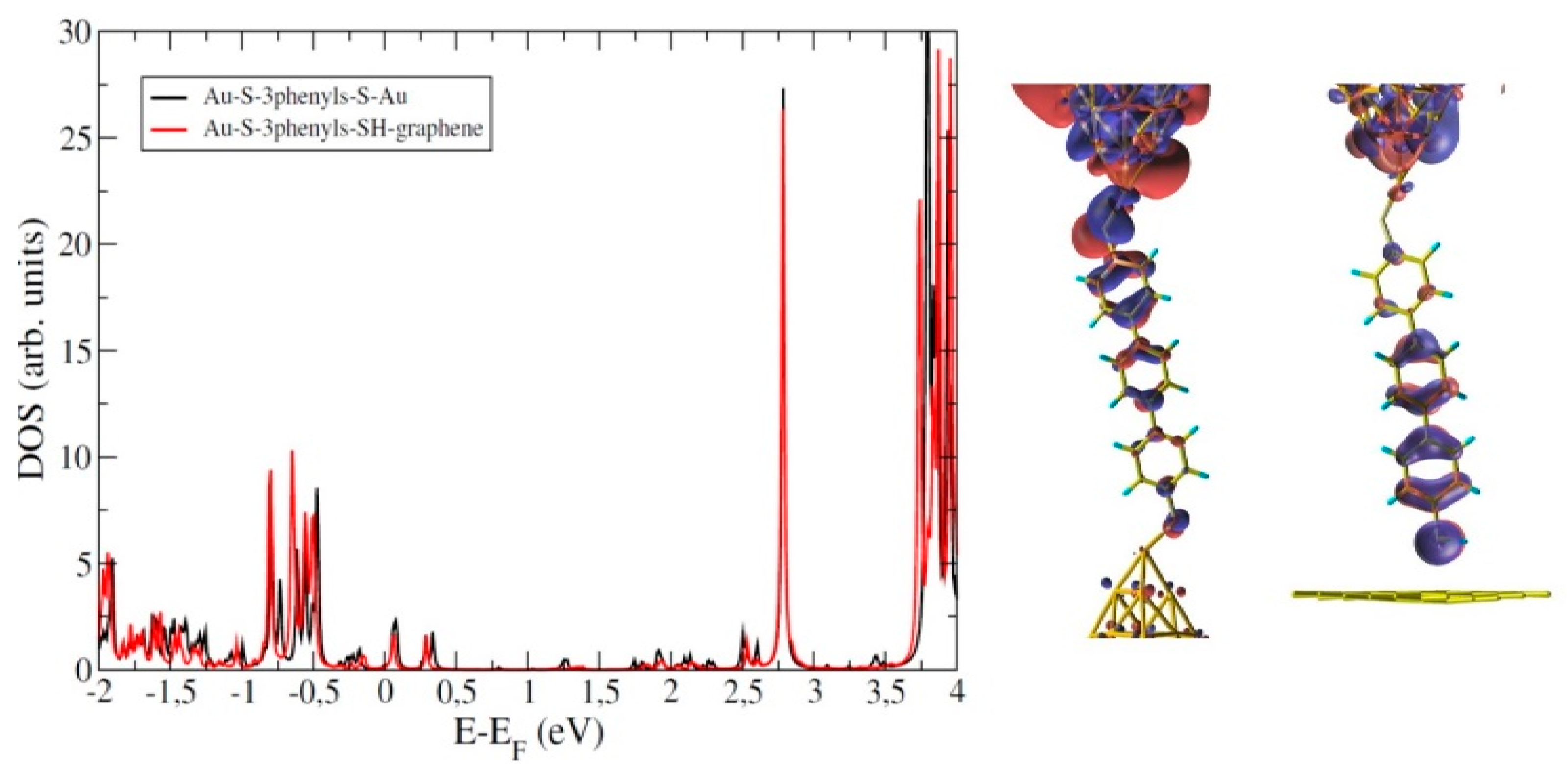
5. Importance of the Molecular Backbone: Conjugated Molecular Wires

In the previous section, we have focused the discussion on alkane molecular chains and we have considered the different parameters which can influence the electronic transport in the junction and consequently the attenuation factor. In particular, we have considered the anchoring groups, in symmetric or asymmetric junctions, and the electrodes, with different metals and with a graphitic tip. Without being exhaustive, it is important also to consider what happens when using another molecular backbone, like conjugated molecular wires. To this end, we chose to have a short look at polyphenylene chains, which are also very common and popular for molecular electronics. These polymers are very interesting, since, as presented in Figure 1 and [15], their attenuation factors are around three times smaller than for the alkane chains, making these molecular wires much more conductive. Hence, with what we have seen by using graphene electrodes, we can expect an even higher conductance for these polymers used in hybrid molecular junctions.
Therefore, hybrid Au–graphene and standard Au–Au molecular junctions have been studied through I(s) measurements and DFT calculations, with polyphenylenes, using thiol and amine anchoring groups, as a direct comparison with alkane-based molecular junctions [50].
Surprisingly, the electronic behavior is very different from what was expected. Indeed, either experimentally or theoretically, almost no difference has been found for the attenuation factors determined for Au–Au and Au–graphene junctions. Moreover, the different anchoring groups, thiol and amine, did not bring any significant difference. Again, this can be better understood from the DOS calculations represented in Figure 8. The projected DOS on the molecular part (including the anchoring group) reveals that there is almost no difference in the electronic structure of each molecular junction. This means that, in this case, the use of a graphene electrode does not break the symmetry, as was the case for the alkane chains. This is further illustrated in Figure 8 with the representation of the spatial extension of the HOMO level for both Au–Au and Au–graphene junctions. In both cases, we can observe a molecular orbital of π symmetry which propagates well along the molecular chain. However, we can also observe that the coupling to the electrodes remains the same in both junctions, despite the introduction of the graphene electrode. In other words, for this system, there is no symmetry breaking induced by the introduction of the graphene electrode. Consequently, the coupling to the electrode or the anchoring group used will have no effect on the electronic structure of the system and therefore on the electronic transport. Hence, the polyphenylene molecular chain solely drives the attenuation factor. From a theoretical point of view, in this case, the Simmons model would not help in discriminating the effect of the anchoring group, whereas a complex bandstructure calculation would probably give the correct attenuation factor, independently of the electrodes or the anchoring groups.

6. Summary

In this review, we have introduced the main electronic transport mechanisms in molecular junctions, to discuss mainly the non-resonant tunneling regime. In particular, we have considered as a characteristic of this regime the attenuation factor in the current exponential decay, observed experimentally and determined theoretically. In this respect, we have discussed the main theoretical approaches proposed to date to describe the attenuation factors. As we have seen, there is unfortunately no universal model to characterize the electronic transport in a molecular junction. Beyond performant DFT calculations, which allow us to calculate the electronic transmission and to deduce the attenuation factor, a full understanding of the electronic transport in a molecular junction remains complicated. Indeed, each present theoretical approach describes either the role of the anchoring group, by considering an accurate evaluation of the molecular levels position with respect to the Fermi level, or the role of the molecular backbone, without considering properly the coupling to the electrode or the interface states related to the anchoring groups. In addition, most of the studies consider symmetric junctions with the same electrodes and same anchoring groups at each molecular side.
Then, we have illustrated these aspects by shortly reviewing experimental and theoretical studies on alkane-based molecular junctions. Starting with standard junctions with gold electrodes at each end, we have also considered a hybrid junction where one gold electrode is substituted by a graphene electrode. In this case, and for different anchoring groups, we have obtained a much reduced attenuation factor. In addition, for some specific anchoring groups, it is even possible to increase the overall conductance of the molecular junction. By considering platinum instead of gold, yielding the same effect, we have deduced that the attenuation factor reduction can be attributed to symmetry breaking induced by the graphene electrode in the molecular junction. Indeed, at one side, the molecule is coupled covalently to the electrode, whereas it is weakly coupled (through van der Waals interactions) at the other side. Another interesting case to consider is a full asymmetric junction, with different anchoring groups and different electrodes at each side. As a result, the most conductive anchoring group, similarly to what happens at the macroscopic scale, mainly drives the conductance. Finally, hybrid junctions with conjugated molecular wires have been studied as well. A much lower attenuation factor could have been expected since these molecules are very conductive, unfortunately, due to bad coupling to the electrodes, the electronic transport properties remain unchanged, independently of the electrodes or the anchoring groups.
To conclude, despite the recent advances in the measurement techniques as well as in the theoretical and computational approaches, a full understanding of the electronic transport mechanism in molecular junctions has not been reached yet. In particular, the theoretical determination of the attenuation factor of the current remains a difficult task due to the lack of universal model to treat this problem. As we have seen, the Simmons model applies in very specific cases where the HOMO level is close to the Fermi level, as in the case of alkanedithiol in hybrid gold–graphene junctions. For other anchoring groups, the difference in symmetry couplings strongly modifies the energetic position of the molecular states, and the Simmons model does not apply anymore. Other theoretical approaches do not apply either since they consider infinite molecular chains and no effect of anchoring groups or electrodes. Therefore, the attenuation factors for these systems are theoretically deduced from this first case in comparison with the standard symmetric junctions, which are well documented in the literature. The attenuation factors of these hybrid junctions are all very similar, due to compensation effects between coupling and conduction in the molecular backbone and coupling to the electrodes. Moreover, we have also observed that the complex bandstructure approach may apply to aromatic molecular chains since the attenuation factors do not differ from the one determined in symmetric junctions. Consequently, a challenging task and an ideal perspective for theoretical approaches in determining attenuation factors in molecular junctions would be to consider, in the meantime, the intrinsic properties of the molecular backbone and the coupling to the electrodes through the anchoring groups that determines the positions of the molecular levels with respect to the Fermi level.

Funding

This research received no external funding.

Conflicts of Interest

The authors declare no conflict of interest.

References

  1. Cuevas, J.C.; Scheer, E. Molecular Electronics: An Introduction to Theory and Experiment; World Scientific: Singapore, 2010. [Google Scholar]
  2. Wang, W.; Lee, T.; Reed, M.A. Mechanism of electron conduction in self-assembled alkanethiol monolayer devices. Phys. Rev. B 2003, 68, 035416. [Google Scholar] [CrossRef]
  3. Sze, S.M. Physics of Semiconductor Devices, 2nd ed.; Wiley: New York, NY, USA, 1981. [Google Scholar]
  4. Hines, T.; Diez-Perez, I.; Hihath, J.; Liu, H.; Wang, Z.S.; Zhao, J.; Zhou, G.; Müllen, K.; Tao, N. Transition from Tunneling to Hopping in Single Molecular Junctions by Measuring Length and Temperature Dependence. J. Am. Chem. Soc. 2010, 132, 11658. [Google Scholar] [CrossRef] [PubMed]
  5. Segal, D.; Nitzan, A.; Davis, W.B.; Wasielewski, M.R.; Ratner, M.A. Electron Transfer Rates in Bridged Molecular Systems 2. A Steady-State Analysis of Coherent Tunneling and Thermal Transitions. J. Phys. Chem. B 2000, 104, 3817. [Google Scholar] [CrossRef] [Green Version]
  6. Nitzan, A. The relationship between electron transfer rate and molecular conduction 2. The sequential hopping case. Isr. J. Chem. 2002, 42, 163. [Google Scholar] [CrossRef]
  7. Yan, H.; Bergren, A.J.; McCreery, R.; Luisa Della Rocca, M.; Martin, P.; Lafarge, P.H.; Lacroix, J.C. Activationless charge transport across 4.5 to 22 nm in molecular electronic junctions. Proc. Natl. Acad. Sci. USA 2013, 110, 5326. [Google Scholar] [CrossRef] [Green Version]
  8. Choi, S.H.; Kim, B.; Frisbie, C.D. Electrical Resistance of Long Conjugated Molecular Wires. Science 2008, 320, 1482. [Google Scholar] [CrossRef]
  9. Von Hippel, A.R. Molecular engineering. Science 1956, 123, 315. [Google Scholar] [CrossRef]
  10. Kamenetska, M.; Koentopp, M.; Whalley, A.C.; Park, Y.S.; Steigerwald, M.L.; Nuckolls, C.; Hybertsen, M.S.; Venkataraman, L. Formation and Evolution of Single-Molecule Junctions. Phys. Rev. Lett. 2009, 102, 126803. [Google Scholar] [CrossRef]
  11. Li, C.; Pobelov, I.; Wandlowski, T.; Bagrets, A.; Arnold, A.; Evers, F. Charge Transport in Single Au | Alkanedithiol | Au Junctions:  Coordination Geometries and Conformational Degrees of Freedom. J. Am. Chem. Soc. 2008, 130, 318. [Google Scholar] [CrossRef] [Green Version]
  12. Li, X.; He, J.; Hihath, J.; Xu, B.; Lindsay, S.M.; Tao, N. Conductance of Single Alkanedithiols: Conduction Mechanism and Effect of Molecule-Electrode Contacts. J. Am. Chem. Soc. 2006, 128, 2138. [Google Scholar] [CrossRef]
  13. Klausen, R.S.; Widawsky, J.R.; Steigerwald, M.L.; Venkataraman, L.; Nuckolls, C. Conductive Molecular Silicon. J. Am. Chem. Soc. 2012, 134, 4541. [Google Scholar] [CrossRef] [PubMed]
  14. Su, T.A.; Li, H.; Zhang, V.; Neupane, M.; Batra, A.; Klausen, R.S.; Kumar, B.; Steigerwald, M.L.; Venkataraman, L.; Nuckolls, C. Single-Molecule Conductance in Atomically Precise Germanium Wires. J. Am. Chem. Soc. 2015, 137, 12400. [Google Scholar] [CrossRef] [PubMed]
  15. Li, H.; Garner, M.H.; Su, T.A.; Jensen, A.; Inkpen, M.S.; Steigerwald, M.L.; Venkataraman, L.; Solomon, G.C.; Nuckolls, C. Extreme Conductance Suppression in Molecular Siloxanes. J. Am. Chem. Soc. 2017, 139, 10212. [Google Scholar] [CrossRef] [PubMed] [Green Version]
  16. Bonifas, A.P.; McCreery, R.L. ‘Soft’ Au, Pt and Cu contacts for molecular junctions through surface-diffusion-mediated deposition. Nat. Nanotechnol. 2010, 5, 612. [Google Scholar] [CrossRef] [PubMed]
  17. He, J.; Chen, F.; Li, J.; Sankey, O.F.; Terazono, Y.; Herrero, C.; Gust, D.; Moore, T.A.; Moore, A.L.; Lindsay, S.M. Electronic Decay Constant of Carotenoid Polyenes from Single-Molecule Measurements. J. Am. Chem. Soc. 2005, 127, 1384. [Google Scholar] [CrossRef] [PubMed]
  18. Capozzi, B.; Dell, E.J.; Berkelbach, T.C.; Reichman, D.R.; Venkataraman, L.; Campos, L.M. Length-Dependent Conductance of Oligothiophenes. J. Am. Chem. Soc. 2014, 136, 10486. [Google Scholar] [CrossRef]
  19. Gunasekaran, S.; Hernangomez-Perez, D.; Davydenko, I.; Marder, S.; Evers, F.; Venkataraman, L. Near Length-Independent Conductance in Polymethine Molecular Wires. Nano Lett. 2018, 18, 6387. [Google Scholar] [CrossRef]
  20. Sedghi, G.; Garcia-Suarez, V.M.; Esdaile, L.J.; Anderson, H.L.; Lambert, C.J.; Martin, S.; Bethell, D.; Higgins, S.J.; Elliott, M.; Bennett, N.; et al. Long-range electron tunnelling in oligo-porphyrin molecular wires. Nat. Nano 2011, 6, 517. [Google Scholar] [CrossRef]
  21. Leary, E.; Limburg, B.; Alanazy, A.; Sangtarash, S.; Grace, I.; Swada, K.; Esdaile, L.J.; Noori, M.; Teresa Gonzalez, M.; Rubio-Bollinger, G.; et al. Bias-Driven Conductance Increase with Length in Porphyrin Tapes. J. Am. Chem. Soc. 2018, 140, 12877. [Google Scholar] [CrossRef]
  22. Brooke, C.; Vezzoli, A.; Higgins, S.J.; Zotti, L.A.; Palacios, J.J.; Nichols, R.J. Resonant transport and electrostatic effects in single-molecule electrical junctions. Phys. Rev. B 2015, 91, 195438. [Google Scholar] [CrossRef] [Green Version]
  23. Sayed, S.Y.; Fereiro, J.A.; Yan, H.; McCreery, R.L.; Bergren, A.J. Charge transport in molecular electronic junctions: Compression of the molecular tunnel barrier in the strong coupling regime. Proc. Natl. Acad. Sci. USA 2012, 109, 11498. [Google Scholar] [CrossRef] [PubMed] [Green Version]
  24. Fereiro, J.A.; McCreery, R.L.; Bergren, A.J. Direct Optical Determination of Interfacial Transport Barriers in Molecular Tunnel Junctions. J. Am. Chem. Soc. 2013, 135, 9584. [Google Scholar] [CrossRef] [PubMed]
  25. Martin, S.; Manrique, D.Z.; Garcia-Suarez, V.M.; Haiss, W.; Higgins, S.J.; Lambert, C.J.; Nichols, R.J. Adverse effects of asymmetric contacts on single molecule conductances of HS(CH2)n COOH in nanoelectrical junctions. Nanotechnology 2009, 20, 125203. [Google Scholar] [CrossRef] [PubMed] [Green Version]
  26. Wang, K.; Zhou, J.; Hamill, J.M.; Xu, B. Measurement and understanding of single-molecule break junction rectification caused by asymmetric contacts. J. Chem. Phys. 2014, 141, 054712. [Google Scholar] [CrossRef] [PubMed] [Green Version]
  27. Evers, F.; Korytar, R.; Tewari, S.; van Ruitenbeek, J.M. Advances and challenges in single-molecule electron transport. Rev. Mod. Phys. 2020, 92, 035001. [Google Scholar] [CrossRef]
  28. Simmons, J.G. Generalized Formula for the Electric Tunnel Effect between Similar Electrodes Separated by a Thin Insulating Film. J. Appl. Phys. 1963, 34, 1793. [Google Scholar] [CrossRef] [Green Version]
  29. Nitzan, A. Electron Transmission Through Molecules and Molecular Interfaces. Ann. Rev. Phys. Chem. 2001, 52, 681. [Google Scholar] [CrossRef] [Green Version]
  30. Tomfohr, J.K.; Sankey, O.F. Complex band structure, decay lengths, and Fermi level alignment in simple molecular electronic systems. Phys. Rev. B 2002, 65, 245105. [Google Scholar] [CrossRef]
  31. Picaud, F.; Smogunov, A.; Corso, A.D.; Tosatti, E. Complex band structures and decay length in polyethylene chains. J. Phys. Condens. Matter. 2003, 15, 3731. [Google Scholar] [CrossRef] [Green Version]
  32. Desjonqueres, M.C.; Spanjaard, D. Concepts in surface physics. In Springer Series in Surface Science; Springer: Berlin, Germany, 1993; Volume 30. [Google Scholar]
  33. Kiguchi, M.; Kaneko, S. Single Molecule Bridging Between Metal Electrodes. Phys. Chem. Chem. Phys. 2013, 15, 2253–2267. [Google Scholar] [CrossRef]
  34. Quek, S.Y.; Choi, H.J.; Louie, S.G.; Neaton, J.B. Length Dependence of Conductance in Aromatic Single-Molecule Junctions. Nano Lett. 2009, 9, 3949–3953. [Google Scholar] [CrossRef] [PubMed]
  35. Peng, Z.L.; Chen, Z.B.; Zhou, X.Y.; Sun, Y.Y.; Liang, J.H.; Niu, Z.J.; Zhou, X.S.; Mao, B.W. Single Molecule Conductance of Carboxylic Acids Contacting Ag and Cu Electrodes. J. Phys. Chem. C 2012, 116, 21699–21705. [Google Scholar] [CrossRef]
  36. Kiguchi, M.; Miura, S.; Hara, K.; Sawamura, M.; Murakoshi, K. Conductance of a Single Molecule Anchored by an Isocyanide Substituent to Gold Electrodes. Appl. Phys. Lett. 2006, 89, 213104. [Google Scholar] [CrossRef] [Green Version]
  37. Park, Y.S.; Whalley, A.C.; Kamenetska, M.; Steigerwald, M.L.; Hybertsen, M.S.; Nuckolls, C.; Venkataraman, L. Contact Chemistry and Single-Molecule Conductance: A Comparison of Phosphines, Methyl Sulfides, and Amines. J. Am. Chem. Soc. 2007, 129, 15768–15769. [Google Scholar] [CrossRef] [PubMed]
  38. Chen, F.; Li, X.; Hihath, J.; Huang, Z.; Tao, N. Effect of Anchoring Groups on Single-Molecule Conductance: Comparative Study of Thiol-, Amine-, and Carboxylic-Acid-Terminated Molecules. J. Am. Chem. Soc. 2006, 128, 15874–15881. [Google Scholar] [CrossRef] [PubMed]
  39. Reed, M.A.; Zhou, C.; Muller, C.J.; Burgin, T.P.; Tour, J.M. Conductance of a Molecular Junction. Science 1997, 278, 252–254. [Google Scholar] [CrossRef] [Green Version]
  40. Xu, B.; Tao, N.J. Measurement of Single-Molecule Resistance by Repeated Formation of Molecular Junctions. Science 2003, 301, 1221–1223. [Google Scholar] [CrossRef] [Green Version]
  41. Cui, X.D.; Primak, A.; Zarate, X.; Tomfohr, J.; Sankey, O.F.; Moore, A.L.; Moore, T.A.; Gust, D.; Harris, G.; Lindsay, S.M. Reproducible Measurement of Single-Molecule Conductivity. Science 2001, 294, 571–574. [Google Scholar] [CrossRef]
  42. Haiss, W.; van Zalinge, H.; Higgins, S.J.; Bethell, D.; Höbenreich, H.; Schiffrin, D.J.; Nichols, R.J. Redox State Dependence of Single Molecule Conductivity. J. Am. Chem. Soc. 2003, 125, 15294. [Google Scholar] [CrossRef]
  43. Castellanos-Gomez, A.; Agraït, N.; Rubio-Bollinger, G. Carbon fibre tips for scanning probe microscopy based on quartz tuning fork force sensors. Nanotechnology 2010, 21, 145702. [Google Scholar] [CrossRef]
  44. Dappe, Y.J.; González, C.; Cuevas, J.C. Carbon tips for all-carbon single-molecule electronics. Nanoscale 2014, 6, 6953. [Google Scholar] [CrossRef] [Green Version]
  45. Zhang, Q.; Liu, L.; Tao, S.; Wang, C.; Zhao, C.; González, C.; Dappe, Y.J.; Nichols, R.J.; Yang, L. Graphene as a promising electrode for low current attenuation in asymmetric molecular junctions. Nano Lett. 2016, 16, 6534. [Google Scholar] [CrossRef]
  46. Zhang, Q.; Tao, S.; Yi, R.; He, C.; Zhao, C.; Su, W.; Smogunov, A.; Dappe, Y.J.; Nichols, R.J.; Yang, L. Symmetry Effects on Attenuation Factors in Graphene-Based Molecular Junctions. J. Phys. Chem. Lett. 2017, 8, 5987–5992. [Google Scholar] [CrossRef] [PubMed]
  47. He, C.; Zhang, Q.; Gao, T.; Liu, C.; Chen, Z.; Zhao, C.; Zhao, C.; Nichols, R.J.; Dappe, Y.J.; Yang, L. Charge transport in hybrid platinum/molecule/graphene single molecule junctions. Phys. Chem. Chem. Phys. 2020, 22, 13498. [Google Scholar] [CrossRef] [PubMed]
  48. He, C.; Zhang, Q.; Tao, S.; Zhao, C.Z.; Zhao, C.; Su, W.; Dappe, Y.J.; Nichols, R.J.; Yang, L. Carbon-contacted single molecule electrical junctions. Phys. Chem. Chem. Phys. 2018, 20, 24553. [Google Scholar] [CrossRef] [PubMed]
  49. He, C.; Zhang, Q.; Fan, Y.; Zhao, C.Z.; Zhao, C.; Ye, J.; Dappe, Y.J.; Nichols, R.J.; Yang, L. Effect of Asymmetric Anchoring Groups on Electronic Transport in Hybrid Metal/Molecule/Graphene Single Molecule Junctions. Chem. Phys. Chem. 2019, 20, 1830. [Google Scholar] [CrossRef] [PubMed]
  50. Tao, S.; Zhang, Q.; He, C.; Lin, X.; Xie, R.; Zhao, C.Z.; Zhao, C.; Smogunov, A.; Dappe, Y.J.; Nichols, R.J.; et al. Graphene-Contacted Single Molecular Junctions with Conjugated Molecular Wires. ACS Appl. Nano Mater. 2019, 2, 12. [Google Scholar] [CrossRef] [Green Version]
Figure 1. Overlay of attenuation plots for eight different molecules constructed from J–V curves with different thicknesses of each structure (the length of the error bars is two standard deviations). The lines are least squares regression lines for aromatic (2.7 nm−1) molecules. The different abbreviations stand for the aromatic molecular names: NP = nitrophenyl, AQ = anthraquinone, NAB = nitroazobenzene, BrB = bromophenyl, EB = ethynylbenzene, AB = azobenzene and BTB = bisthienylbenzene. Adapted figure from [23] and with permission. Copyright (2010) American Chemical Society.
Applsci 10 06162 g001
Figure 2. Schematic representation of the bridge model with N sites of energy ε1, ε2… εN coupled through hoppings t1,2, t2,3, …. tN-1,N and bridging the left and right electrodes. Reprinted figure from [1] and with permission. Copyright (2010) World Scientific.
Applsci 10 06162 g002
Figure 3. Calculated complex bandstructure for an infinite alkane molecular chain. The left and right part of the graph correspond to the imaginary and real wavevectors, respectively. The attenuation factor can be read on the horizontal axis, in the imaginary wavevector part, considering the localized state with the smallest extension (semielliptical-like curve). Reprinted figure from [30] and with permission. Copyright (2002) by the American Physical Society.
Applsci 10 06162 g003
Figure 4. (Left) Schematic representation of the hybrid metal–molecule junction formed in the experiment for conductance measurements. (Right) Evolution of the conductance as a function of the molecular length: experimental measurements on asymmetric metal–graphene junction (black), experimental measurements on symmetric metal–metal junction (blue) and conductance calculation on asymmetric metal–graphene junction (red). Reprinted figure from [40] and with permission. Copyright (2016) American Chemical Society.
Applsci 10 06162 g004
Figure 5. (Left) Evolution of the conductance as a function of the molecular length for molecular junctions with different anchoring groups and electrodes: conductance calculation on Au–graphene junctions with amine group (green), conductance measurements on Au–graphene junctions with amine group (black), conductance measurements on Au–graphene junctions with thiol group (red) and conductance measurements on Au–Au junctions with amine group (blue). (Right) Density functional theory (DFT) calculated density of states (DOS) for Au–graphene and Au–Au molecular junctions with amine anchoring groups. Reprinted figure from [46] and with permission. Copyright (2017) American Chemical Society.
Applsci 10 06162 g005
Figure 6. Atomic representation of the different hybrid Au–graphene alkane-based molecular junctions using thiolate and carboxylic acid anchoring groups at each extremity. Reprinted figure from [49] and with permission. Copyright (2019) Wiley-VCH Verlag GmbH & Co.
Applsci 10 06162 g006
Figure 7. DFT calculated electronic transmissions for Au–graphene molecular junctions with carboxylic acid anchoring groups at each extremity (pink) and a thiol group at one extremity and a carboxylic acid at the other one (blue). Reprinted figure from [49] and with permission. Copyright (2019) Wiley-VCH Verlag GmbH & Co.
Applsci 10 06162 g007
Figure 8. (Left) DFT calculated projected density of states for Au–graphene and Au–Au triphenyl molecular junctions using thiol groups. (Right) Representation of the corresponding HOMO wavefunction for both junctions. Reprinted figure from [50] and with permission. Copyright (2019) American Chemical Society.
Applsci 10 06162 g008

