Article

Heuristic Global Optimization of an Adaptive Fuzzy Controller for the Inverted Pendulum System: Experimental Comparison

by
Miguel Llama
1,
Alejandro Flores
2,
Ramon Garcia-Hernandez
1,* and
Victor Santibañez
1
1
Tecnologico Nacional de Mexico/Instituto Tecnologico de La Laguna, Blvd. Revolucion y Av. Instituto Tecnologico de La Laguna S/N, Col. Centro, Torreon C.P. 27000, Coahuila, Mexico
2
Continental Automotive Guadalajara Mexico, Camino a la Tijera No. 3 Km 3.5, Carretera Guadalajara-Morelia, Tlajomulco de Zuñiga C.P. 45645, Jalisco, Mexico
*
Author to whom correspondence should be addressed.
Appl. Sci. 2020, 10(18), 6158; https://doi.org/10.3390/app10186158
Submission received: 15 July 2020 / Revised: 30 August 2020 / Accepted: 2 September 2020 / Published: 4 September 2020
(This article belongs to the Special Issue Control and Soft Computing)

Abstract

:
In this paper an adaptive fuzzy controller is proposed to solve the trajectory tracking problem of the inverted pendulum on a cart system. The designed algorithm is featured by not using any knowledge of the dynamic model and incorporating a full-state feedback. The stability of the closed-loop system is proven via the Lyapunov theory, and boundedness of the solutions is guaranteed. The proposed controller is heuristically tuned and its performance is tested via simulation and real-time experimentation. For this reason, a tuning method is investigated via evolutionary algorithms: particle swarm optimization, firefly algorithm and differential evolution in order to optimize the performance and verify which technique produces better results. First, a model-based simulation is carried out to improve the parameter tuning of the fuzzy systems, and then the results are transferred to real-time experiments. The optimization procedure is presented as well as the experimental results, which are also discussed.

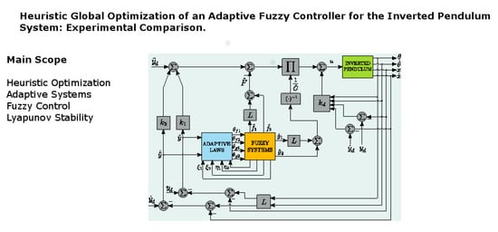
Graphical Abstract

1. Introduction

An inverted pendulum system is known as an underactuated mechanism, the main objective of which is to maintain in a vertical position a rod that rolls freely. Particularly, the inverted pendulum on a cart is composed by a rail on which the cart is mounted and has horizontal linear movement whereas the rod is attached to it. This is one of the most known inverted pendulum configurations and it is the plant under study of this work. Such a system is highly nonlinear, underactuated and it has an unstable equilibrium point, which makes it a pretty challenging exercise; for those reasons, it has become an important, well established and extensively studied problem in control theory.
Regarding inverted pendulums, several examples of applications can be found in sectors such as aerospace, biomechanics and transport. For example, in aerospace, active control of a rocket is required to keep it in an upside-down vertical position during takeoff. Here, the angle of inclination of the rocket is controlled by varying the angle of application of the thrust force, placed at the base of said rocket.
In biomechanics the inverted pendulum is frequently used to model walking bipeds, such as the humanoid robots. In biped robots, the support leg in contact with the ground is often modeled as an inverted pendulum, while the moving leg behaves like a pendulum that oscillates freely, suspended from the hip of the humanoid. Finally, it can be seen that a Segway human transporter is an inverted pendulum, the control of which is based on sensory inputs of gyroscopes mounted at the base of the Segway and a computer control system that maintains the balance while people walk on the vehicle.
As well as the examples shown above, there are many others associated with the applications of inverted pendulums, among which are the stabilization of cranes, the stabilization of the balancing of ships and cars, the positioning of a satellite, etc. Therefore, a study of inverted pendulum systems is an excellent starting point for understanding problems in dynamics and nonlinear control.
Fuzzy adaptive techniques have been successfully applied to several control problems like in [1], where a fuzzy adaptive scheme is proposed to achieve the motion control objective of robot manipulators and it is implemented in a two degree of freedom robotic arm. Fundamentally, fuzzy adaptive control is a nonlinear scheme that uses fuzzy systems with adjustable parameters as function approximators, which compute the control law without necessarily having to incorporate the dynamic model of the plant [2]. This kind of controllers may be robust enough and can deal with high nonlinear effects or with dynamics of the plant that changes during a task execution. That means, fuzzy adaptive controllers can compensate diverse phenomena, such as uncertainties, unmodeled dynamics or unknown variation in the parameters of the plant. That is one of the motivations to tackle the control of the inverted pendulum system through a fuzzy adaptive algorithm.
There exists a wide frame of previous works for the control of the inverted pendulum problem, and several of them with fuzzy adaptive approaches. However, most of them address the problem as a second-order system based on feedback linearization, dealing only with the rod dynamics and leading to the presence of unstable zero dynamics (the cart dynamics). Consequently, this might conduct to undesired behavior of the cart or hindering the experimental implementation of the controllers (as stated in [3]). In [4] a fuzzy adaptive controller in combination with a sliding mode action is proposed for operation of an inverted pendulum. The fuzzy system compensates for the plant nonlinearities and forces the inverted pendulum to track a prescribed reference model. When matching with the model occurs, the pendulum is stabilized at an upright position and the cart should return to its zero position. In [5], an adaptive fuzzy algorithm is designed for the tracking of the cart and stabilization of the pendulum; nevertheless, a PD action had to be incorporated to deal with the states of the cart (position and velocity). The controller was successfully applied in experimentation but the stability of the overall closed-loop system is not studied and it is an open problem.
More recent efforts have been made to take into account the states of the cart in this kind of scheme. In [6] an adaptive PD-like fuzzy controller is used with a good performance but only simulation results are presented and the stability of the algorithm is not proven. In [7], the authors present the study of dynamic response of the inverted pendulum in terms of classical control theory. Theoretical and experimental results using LQR design are presented. In [8] motion equations of a linear inverted pendulum system, and classical and artificial intelligence adaptive control algorithms are designed and implemented for real-time control. Classic PID controller and PID fuzzy logic controller methods are used to control the system. However, the authors in [7,8] do not use evolutionary techniques, nor is a stability analysis is presented. In [9], the authors present the design of a fuzzy-evidential controller in order to realize the stability control of the planar inverted pendulum system. The authors do not present a stability analysis.
In this paper we propose an adaptive fuzzy controller with a full-state feedback, i.e., a feedback of the four states of the inverted pendulum system (positions and velocities of both, pendulum and cart). This algorithm is meant to solve the trajectory tracking of the cart and the stabilization of the pendulum at the unstable equilibrium (vertical position). The full-state feedback action is inspired in the work presented by [3], where the nominal dynamic model of the plant is used in the control equation and only the disturbances are monitored through an adaptive fuzzy system. However, the stability of the system in closed-loop with the total control law is not studied. Those are the main differences regarding this work since the algorithm proposed here does not use any knowledge of the dynamic model; the adaptive fuzzy systems estimate the plant dynamics. The stability of the total control law and the adaptive fuzzy action together with the full-state feedback is proven through a classic adaptive system analysis [10] based on the Lyapunov theory. The latter guarantees that the solutions (positions and velocities of pendulum and cart) are bounded.
Another part of this paper deals with the application of evolutionary algorithms (EA), which are a subset of evolutionary computing and they can be considered as generic optimization metaheuristic algorithms. Most EA are based upon swarm intelligence or bio-inspired computation and they have been gaining wide interest and attention in the community of optimization since they have some advantages in comparison to classic (deterministic) algorithms. Some of those advantages are that EA can address a problem even in the presence of discontinuities in the objective function and they can find optimal or near optimal solutions in big multi-dimensional search spaces with no dependence of the initial guess [11].
Applications of EA have been done mainly in engineering problems. Particularly in control engineering, there exists a vast literature mainly used for tuning parameters in control equations. In [12] the authors propose the use of the differential evolution (DE) algorithm with fuzzy logic for parameter adaptation in the optimal design of fuzzy controllers for nonlinear plants. The DE algorithm is enhanced using Type-1 and Interval Type-2 fuzzy systems for achieving dynamic adaptation of the mutation parameter. Four control optimization problems in which the DE algorithm optimizes the membership functions of the fuzzy controllers are presented. In [13] a variant of the firefly algorithm (FFA) is presented as a tuning method to obtain, in simulation, the gains of a PID controller, which is implemented for a linear model of an automatic voltage regulator. In fuzzy control, there have been also works on the applications of EA to adjust the fuzzy systems used; for instance, in [14] the optimization of a sectorial Mamdani-type fuzzy controller for a two degrees of freedom robot is reported. Particle swarm optimization (PSO) is employed to adjust the centers and standard deviations of the input and output membership functions; scopes of research are limited to simulation. In [15] a method for “optimal design” of an interval type-2 fuzzy control is presented. The control law is applied to a linear plant in simulation. The centers and standard deviations of the upper type-2 membership functions are adjusted in a restricted footprint of uncertainty, limiting in that way the search space of the optimization problem. The human evolutionary algorithm is used and three different objective functions are proposed. In [16], a combination of approximate feedback linearization and sliding mode control approaches is applied to stabilize a fourth-order under-actuated nonlinear inverted pendulum system. A new version of PSO is implemented. The obtained results are illustrated in simulation and do not show a stability analysis. In [17], an approach for automating and facilitating the inverted cart-pendulum (ICP) control in one step is proposed. A holistic optimization is performed by a simplified Ant Colony Optimization method with a constrained Nelder–Mead algorithm (ACO-NM). Simulation results on an ICP nonlinear model show that ACO-NM in the holistic approach is effective compared to other algorithms. Stability analysis is not proven and no real-time experiments are presented.
In sum, our contributions can be described as follows:
  • The proposed algorithm does not use any knowledge of the plant. Unlike previous works, a formal stability analysis of the closed-loop system is proven via Lyapunov theory and therefore, boundedness of the solutions (position and velocity of the pendulum on a cart) is guaranteed.
  • A comparison among several evolutionary techniques are carried out in simulation, and then successfully exported to real-time experiments without any change in the optimized membership functions; only the gains of the controller were tuned again.
This paper is organized as follows: In Section 2, the modeling of the inverted pendulum on a cart system is described, as well as a brief explanation of the fuzzy systems considered. A review of the evolutionary algorithms PSO, DE and FFA used in order to optimize the performance of the adaptive fuzzy controller is also presented. In addition, the proposed controller design is derived and the stability analysis is developed. In Section 3, control and optimization results are presented. Finally, Section 4 concludes about some contributions of the proposed control strategy.

2. Methodology

2.1. Dynamics of the Inverted Pendulum System

Modeling of the inverted pendulum on a cart can be computed considering its free body diagram, which is shown in Figure 1,
Where the states of the system are
x = cart position [ m ] x ˙ = cart velocity m / s θ = angular position of the pendulum [ rad ] θ ˙ = angular velocity of the pendulum rad / s
which can be collected in the vector x = θ θ ˙ x x ˙ T . On the other hand, M [kg] is the mass of the cart, m [kg] is the mass of the pendulum, l [m] is the length to the center of mass of the pendulum, u [N] is the control input and g m s 2 is the gravity acceleration. Then, the dynamic model of this system can be computed from motion equations of Lagrange as suggested in [18], and it can be presented in a nonlinear state space equation as
d d t θ θ ˙ x x ˙ = θ ˙ f 1 ( x ) + g 1 ( x ) u x ˙ f 2 ( x ) + g 2 ( x ) u
with
f 1 ( x ) = Δ ( γ 2 θ ˙ 2 sin θ cos θ α δ sin θ ) f 2 ( x ) = Δ ( γ β θ ˙ 2 sin θ + γ δ sin θ cos θ ) g 1 ( x ) = Δ γ cos θ g 2 ( x ) = Δ β
where α = m + M , β = m l 2 + I , γ = m l , δ = m g l , Δ = 1 / ( α β γ 2 cos 2 θ ) have been used to simplify the representation, and I is the moment of inertia.
Now, by using the approach given in [3], the fourth-order system (1) is put in function of the actuated state and the unactuated state by selecting a suitable output y as
y = L θ + x
where L is a design constant. The new states in function of the actuated and unactuated outputs are given by
d d t y y ˙ = y ˙ F ( x ) + G ( x ) u
where
F ( x ) = L f 1 ( x ) + f 2 ( x )
G ( x ) = L g 1 ( x ) + g 2 ( x )
A system modeled by (3) is to be used to represent the dynamics of the inverted pendulum on a cart and it is the objective plant to control in the following sections. It is important to note that this mathematical model is only required for simulations and not for the real-time implementation.

2.2. Fuzzy Systems Description

In this section, a concise explanation of the fuzzy systems considered in this paper is presented, which perform a mapping from U R 2 to V R . Also we recall an outstanding result in function approximation of fuzzy systems.
Consider the fuzzy systems f ^ i and g ^ i ( i = 1 , 2 ) for the case of two inputs ϕ i j ( j = 1 , 2 ), i.e., f ^ i ( ϕ i 1 , ϕ i 2 ) and g ^ i ( ϕ i 1 , ϕ i 2 ) , where ϕ i 1 ϕ i 2 U f i R 2 and ϕ i 1 ϕ i 2 U g i R 2 , and one output ζ f i V f i R and ζ g i V g i R respectively. Each input variable ϕ i j is defined by p i j fuzzy sets A i j l i j ( l i j = 1 , 2 , , p i j ), each one of them characterized by a membership function μ A i j l i j ( ϕ i j ) , and each one of the output membership functions ζ f i l i 1 l i 2 , ζ g i l i 1 l i 2 is corresponded by a singleton function type.
Such systems f ^ i and g ^ i are constructed from the set of j = 1 2 p i j fuzzy IF-THEN rules in the forms
I F ϕ i 1 is A i 1 l i 1 A N D ϕ i 2 is A i 2 l i 2 T H E N f ^ i is ζ f i l i 1 l i 2 I F ϕ i 1 is A i 1 l i 1 A N D ϕ i 2 is A i 2 l i 2 T H E N g ^ i is ζ g i l i 1 l i 2
Moreover, if specifically product inference engine and center average defuzzifier are employed, the fuzzy system f ^ i ( ϕ i 1 , ϕ i 2 ) can be represented as
f ^ i = l i 1 = 1 p i 1 l i 2 = 1 p i 2 ζ f i l i 1 l i 2 j = 1 2 μ A i j l i j ( ϕ i j ) l i 1 = 1 p i 1 l i 2 = 1 p i 2 j = 1 2 μ A i j l i j ( ϕ i j ) .
and g ^ i ( ϕ i 1 , ϕ i 2 ) as
g ^ i = l i 1 = 1 p i 1 l i 2 = 1 p i 2 ζ g i l i 1 l i 2 j = 1 2 μ A i j l i j ( ϕ i j ) l i 1 = 1 p i 1 l i 2 = 1 p i 2 j = 1 2 μ A i j l i j ( ϕ i j ) .
Let ζ ( · ) i l i 1 l i 2 be the free parameters or adjustable parameters, which can be collected into a vector θ ( · ) i R j = 1 2 p i j , i.e., θ ( · ) i = ζ ( · ) i 11 ζ ( · ) i p i 1 p i 2 T , then (6) and (7) can be rewritten respectively as
f ^ i ( ϕ i 1 , ϕ i 2 | θ f i ) = θ f i T ξ i ( ϕ i 1 , ϕ i 2 )
g ^ i ( ϕ i 1 , ϕ i 2 | θ g i ) = θ g i T η i ( ϕ i 1 , ϕ i 2 )
where ξ i = ξ i 11 ξ i p i 1 p i 2 T R j = 1 2 p i j and η i = η i 11 η i p i 1 p i 2 T R j = 1 2 p i j are the regressor vectors of which the l i 1 l i 2 -th elements (in function of ϕ i 1 , ϕ i 2 ) are given respectively by
ξ i l i 1 l i 2 = j = 1 2 μ A i j l i j ( ϕ i j ) l i 1 = 1 p i 1 l i 2 = 1 p i 2 j = 1 2 μ A i j l i j ( ϕ i j )
η i l i 1 l i 2 = j = 1 2 μ A i j l i j ( ϕ i j ) l i 1 = 1 p i 1 l i 2 = 1 p i 2 j = 1 2 μ A i j l i j ( ϕ i j ) .
By using the result obtained in [2], it follows that for any given real continuous function f ( ϕ ) defined on a compact set U R n , and with arbitrary ϵ f > 0 , there exists a fuzzy system (6) such that
sup ϕ U | f ( ϕ ) f ^ ( ϕ ) | < ϵ f .

2.3. Evolutionary Algorithms for Optimization

In this section we provide a brief review of the algorithms used to solve the performance improvement problem previously stated. Key components, structure and terminology of every algorithm are presented. These concepts and theory have been extracted from [11], where further information about evolutionary algorithms is available.

2.3.1. Particle Swarm Optimization—PSO

PSO was introduced by [19] and several variants that extend the standard PSO have been developed since then. One of the most noteworthy improvements is the use of an inertia function, which is equivalent to introduce a virtual mass to stabilize the search and improve the convergence of the algorithm. PSO with inertia function was proposed in [20] and further studied in [21]; such a variant is used in this research and its description is the following.
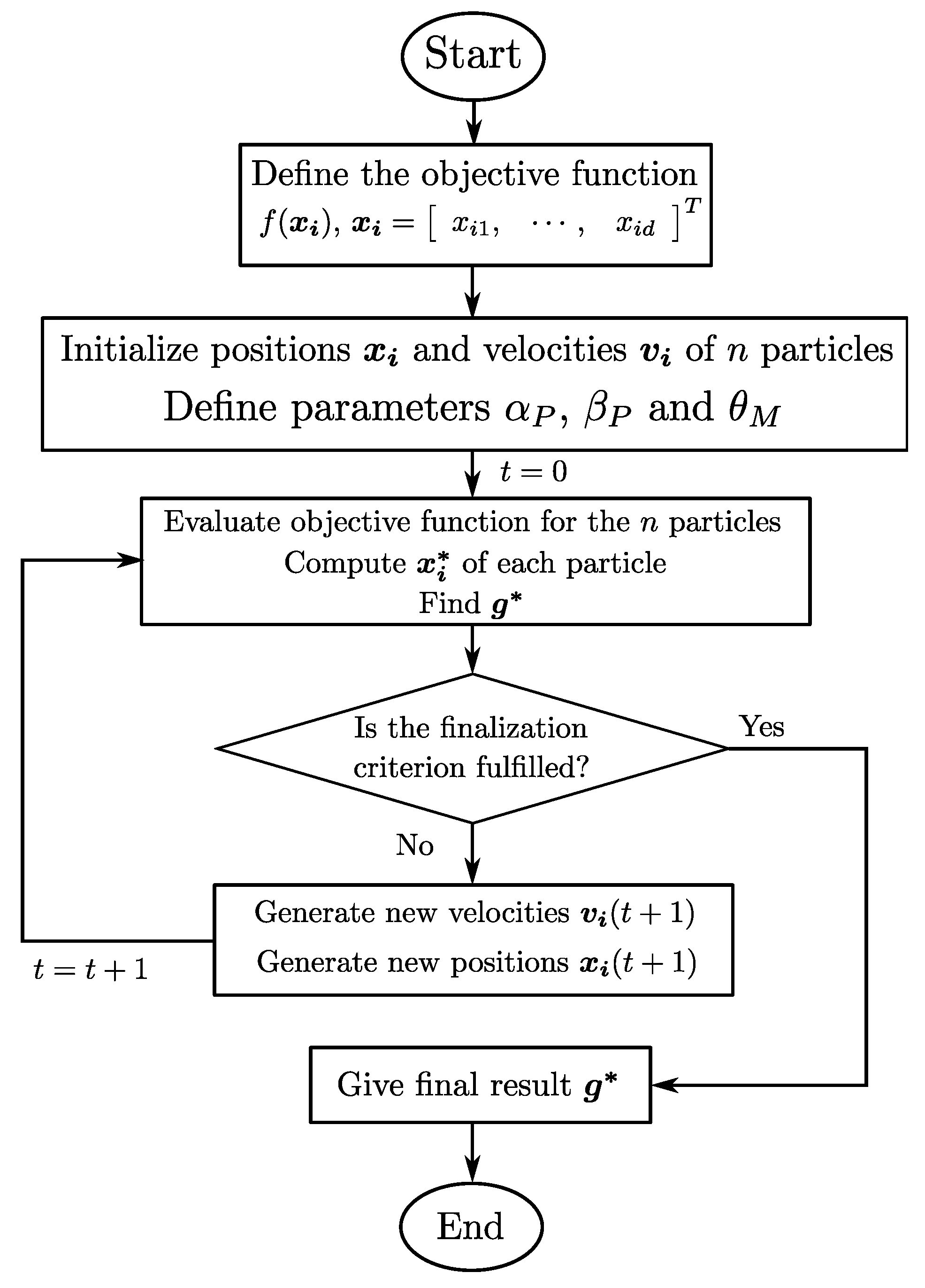
PSO searches in the space of an objective function by adjusting the trajectories of individual agents called particles. The movement of each particle is composed by two main components: a stochastic and a deterministic component, in which every particle is attracted to both: the position of the current global best g * and to its own best position in history x i * , while at the same time it has a tendency to move randomly. The set or array of particles is known as a swarm. Now, we analyze the algorithm itself.
Let x i ( t ) R d i.e., x i ( t ) = [ x i 1 x i d ] T , be the position vector and v i ( t ) R d i.e., v i ( t ) = [ v i 1 v i d ] T the velocity vector of a particle i respectively, where d is the dimension of the search space. Then, the new velocity is determined by
v i ( t + 1 ) = θ M v i ( t ) + α P ϵ 1 ( g * x i ( t ) ) + β P ϵ 2 ( x i * x i ( t ) )
where, ϵ 1 and ϵ 2 are two random numbers that take values between 0 and 1. Parameters α P and β P are the learning parameters or acceleration constants which typically take approximate values of 2, for example, α P β P 2 . θ M ( t ) is the inertia function and takes values between 0 and 1. In the most simple case the inertia function can be considered as a constant, i.e., θ M ( t ) = θ M , and typically θ M 0.5∼0.9 is used.
On the other hand, the new position of particle i is updated by
x i ( t + 1 ) = x i ( t ) + v i ( t + 1 )
The fundamental steps of the PSO algorithm can be summarized as it is shown in Figure 2.

2.3.2. Differential Evolution—DE

It was developed in [22] and further studied in [23]. It is a vector-based metaheuristic algorithm with explicit crossover and mutation equations. DE is based on a population of n size where each individual is represented by a vector x i ( t ) R d for i = 1 , 2 , , n in the d-dimensional search space, i.e.,
x i ( t ) = [ x i 1 x i d ] T
Every element of the vector x i is called a chromosome or genome.
In this paper we used a DE variant in which the mutation scheme uses the best current solution and two difference vectors, and in which the crossover scheme is the binomial. Such variant is known as DE/Best/2/Bin and its description is given as follows.
The mutation process generates a so-called donor vector, which is given by
v i ( t + 1 ) = x b ( t ) + F 1 ( x q ( t ) x r ( t ) ) + F 2 ( x 1 x 2 )
where x b is the best current solution, x q and x r are two distinct vectors selected randomly from the population, x 1 and x 2 are two vectors of dimension d, the elements of which are generated from a Gaussian distribution or uniform distribution with values between 0 and 1. F 1 is a constant parameter often referred to as differential weight and F 2 R d × d is a diagonal matrix in which the elements are positive constants that act as scaling factors. Note that the last two terms in the right-hand side of (13) are the two difference vectors mentioned above.
On the other hand, the crossover stage produces a vector u i and is controlled by the crossover parameter C r [ 0 , 1 ] , which controls the rate or probability for crossover. In the binomial scheme two different numbers must be generated: a uniformly distributed random number r i [ 0 , 1 ] and index J r i { 1 , 2 , , d } computed randomly by permutation. Then every entry of vector u i is obtained by
u i j ( t + 1 ) = v i j ( t ) if r i C r or j = J r i x i j ( t ) if r i > C r and j J r i
Finally, in the selection process, the fittest individual is chosen, i.e., the individual who got a better value for the objective function. For a minimization approach the fittest individual is the one who obtained the lowest value when evaluated for the objective function; this can be mathematically expressed by
x i ( t + 1 ) = u i ( t + 1 ) if f ( u i ( t + 1 ) ) f ( x i ( t ) ) x i ( t ) if f ( u i ( t + 1 ) ) > f ( x i ( t ) )
Components of the DE algorithm used here can be seen schematically in Figure 3.

2.3.3. Firefly Algorithms—FFA

FFA was first developed and published in [24] and is based upon the flashing patterns and behavior of fireflies. In this algorithm the position of a firefly is referred by a vector x i of dimension d, which evaluates the objective function f ( x ) , x = [ x 1 x d ] T .
The absolute attractiveness or long distance attraction of a firefly i is equal to its brightness B i which is determined by the objective function. For the minimization problem, the brightest firefly, and therefore the firefly with the most absolute attractiveness, is the one that gets the lowest value of the objective function. In this minimization approach the brightness (absolute attractiveness) of a firefly i can be determined by
B i = 1 f ( x i ) .
In the FFA process, for any two fireflies, the less brighter one (the firefly with less absolute attractiveness) will move toward the brighter one (the firefly with more absolute attractiveness). Nevertheless this movement is governed by the local attraction or relative attractiveness between two fireflies, which decreases as distance between those two fireflies increases.
Relative attractiveness can be defined as the brightness of a firefly i seen by a firefly j, which is expressed by
β F = β 0 e γ F r i j 2
where γ F > 0 is a light absorption coefficient, β 0 > 0 is an attractiveness for r i j = 0 , and r i j is the distance between any two fireflies i, j which is defined as
r i j = x i x j = k = 1 d ( x i k x j k ) 2
where x ( · ) k is the k-th element of firefly x ( · ) . On the other hand, the movement of a firefly i attracted toward another firefly j with more absolute attractiveness is determined by
x i ( t + 1 ) = x i ( t ) + β 0 e γ F r i j 2 ( x j ( t ) x i ( t ) ) + α 0 e η F t ϵ i ( t )
The second term in the right-hand side of (19) stands for the relative attractiveness; the third term is a randomness action where α 0 R d × d is a diagonal matrix in which the positive elements are considered as scaling factors, while η F > 0 is an attenuation constant and ϵ i ( t ) is a vector of which the entries are random numbers drawn by a uniform distribution or a Gaussian distribution in the bounds [ 0 , 1 ] .
Here the output of the algorithm or the final result is the brightest firefly when the finalization criterion is met.
The fundamental steps of FFA are summarized as shown in Figure 4.

2.4. Proposed Controller Design

The control objective for the inverted pendulum system, in this paper, is defined as the stabilization of the pendulum at its upwards vertical position (unstable equilibrium), while the cart follows a given reference trajectory. In the following, the dynamics of the system in function of a defined error is presented, then the proposed full-state feedback adaptive fuzzy controller is described and its stability is proven.

2.4.1. Controller Design

Let us define the generalized error vector as
e = y ˜ y ˜ ˙ T ,
where y ˜ = y d y is the generalized error, with y d being the desired output which is given by (2), i.e., y d = L θ d + x d , where θ d and x d are the desired position of the pendulum and the desired trajectory of the cart respectively. By combining Equations (3) and (20) we get
e ˙ = d d t y ˜ y ˜ ˙ = y ˜ ˙ F ( x ) G ( x ) u + y ¨ d
which can be considered as the error dynamics. Now to fulfill the control objective we designed a controller u such that the plant (21) follows accurately the desired output y d , or in other words to keep the error y ˜ bounded. The proposed control law is given by
u = 1 G ^ [ F ^ + k T e + y ¨ d ] + k d T x ˜
where F ^ = L f ^ 1 ( θ , θ ˙ | θ f 1 ) + f ^ 2 ( x , x ˙ | θ f 2 ) and G ^ = L g ^ 1 ( θ , θ ˙ | θ g 1 ) + g ^ 2 ( x , x ˙ | θ g 2 ) are the adaptive fuzzy actions which estimate F ( x ) and G ( x ) respectively, and
k = k 1 k 2 T ; k d = k d 1 k d 2 k d 3 k d 4 T x ˜ = θ θ ˙ x d x x ˙ d x ˙ T
where k 1 , k 2 are positive constants and k d i for i = 1 , , 4 , are suitable feedback control gains.
The adaptive fuzzy systems f ^ 1 ( θ , θ ˙ | θ f 1 ) , f ^ 2 ( x , x ˙ | θ f 2 ) , g ^ 1 ( θ , θ ˙ | θ g 1 ) , and g ^ 2 ( x , x ˙ | θ g 2 ) are constructed as those described by (6) and (7) and may be expressed as in (8) and (9), i.e.,
f ^ 1 ( θ , θ ˙ | θ f 1 ) = ξ 1 T θ f 1 , f ^ 2 ( x , x ˙ | θ f 2 ) = ξ 2 T θ f 2 g ^ 1 ( θ , θ ˙ | θ g 1 ) = η 1 T θ g 1 , g ^ 2 ( x , x ˙ | θ g 2 ) = η 2 T θ g 2
On the other hand, the adaptive laws used to update the free parameters were designed as
θ ˙ f 1 = γ 1 L e T P b ξ 1 ( θ , θ ˙ )
θ ˙ f 2 = γ 2 e T P b ξ 2 ( x , x ˙ )
θ ˙ g 1 = γ 3 L e T P b η 1 ( θ , θ ˙ ) u
θ ˙ g 2 = γ 4 e T P b η 2 ( x , x ˙ ) u
where P and b are defined further on in (33) and (28) respectively.
The block diagram of the proposed controller is shown in Figure 5. The closed-loop equation is gotten by substituting control law (22) into system (21) and under some manipulations it can be expressed as
e ˙ = y ˜ ˙ ( F ^ F ) + ( G ^ G ) u k T e G ^ k d T x ˜
or also, it may be written into the vector form
e ˙ = A e + b ( F ^ F ) + ( G ^ G ) u G ^ k d T x ˜
where
A = 0 1 k 1 k 2 , b = 0 1

2.4.2. Stability Analysis

Let θ f i * R j = 1 2 p i j and θ g i * R j = 1 2 p i j ( i = 1 , 2 ) be the vector of optimal parameters such that the fuzzy systems
f ^ 1 * ( θ , θ ˙ | θ f 1 * ) = ξ 1 T θ f 1 * , f ^ 2 * ( x , x ˙ | θ f 2 * ) = ξ 2 T θ f 2 * g ^ 1 * ( θ , θ ˙ | θ g 1 * ) = η 1 T θ g 1 * , g ^ 2 * ( x , x ˙ | θ g 2 * ) = η 2 T θ g 2 *
are the best approximators of their corresponding nominal functions f 1 , f 2 , g 1 and g 2 . Then, we define the minimum approximation error as
w = [ F ^ * F ] + [ G ^ * G ] u + [ G G ^ ] k d T x ˜
where F ^ * = L f ^ 1 * ( θ , θ ˙ | θ f 1 * ) + f ^ 2 * ( x , x ˙ | θ f 2 * ) and G ^ * = L g ^ 1 * ( θ , θ ˙ | θ g 1 * ) + g ^ 2 * ( x , x ˙ | θ g 2 * ) . By using w we can now express (27) as
e ˙ = A e + b [ L ( f ^ 1 f ^ 1 * ) + ( f ^ 2 f ^ 2 * ) + L ( g ^ 1 g ^ 1 * ) + ( g ^ 2 g ^ 2 * ) G k d T x ˜ + w ]
or well
e ˙ = A e + b [ L ( ξ 1 T θ f 1 ξ 1 T θ f 1 * ) ] + ( ξ 2 T θ f 2 ξ 2 T θ f 2 * ) + L ( η 1 T θ g 1 η 1 T θ g 1 * ) + ( η 2 T θ g 2 η 2 T θ g 2 * ) G k d T x ˜ + w
Finally, let us define
θ ˜ = θ ˜ f 1 θ ˜ f 2 θ ˜ g 1 θ ˜ g 2 T
where every element θ ˜ ( · ) = θ ( · ) θ ( · ) * . Then, by considering these elements into (30), we can obtain a closed-loop dynamic equation given by
e ˙ = A e + b [ L ξ 1 T θ ˜ f 1 + ξ 2 T θ ˜ f 2 + L η 1 T θ ˜ g 1 + η 2 T θ ˜ g 2 G k d T x ˜ + w ]
which specifies explicitly the relationship between the generalized error e and the fuzzy parameters estimation error θ ˜ .
In order to achieve the analysis of boundedness of the solutions, the following Lyapunov function candidate is proposed
V ( e , θ ˜ ) = 1 2 e T P e + 1 2 θ ˜ T Γ 1 θ ˜
which is globally positive definite and radially unbounded since Γ R 4 × 4 is a diagonal matrix of which non-zero elements γ k ( k = 1 , , 4 ) are positive constants also known as adaptive gains, P R 2 × 2 is a positive definite matrix.
Then, the time derivative of V ( e , θ ˜ ) along of the solution trajectories of the closed-loop system (32) results in
V ˙ ( e , θ ˜ ) = 1 2 e T P e ˙ + 1 2 e ˙ T P e + θ ˜ T Γ 1 θ ˜ ˙
V ˙ ( e , θ ˜ ) = 1 2 e T P [ A e + b [ L ξ 1 T θ ˜ f 1 + ξ 2 T θ ˜ f 2 + L η 1 T θ ˜ g 1 + η 2 T θ ˜ g 2 G k d T x ˜ + w ] ] + 1 2 [ A e + b [ L ξ 1 T θ ˜ f 1 + ξ 2 T θ ˜ f 2 + L η 1 T θ ˜ g 1 + η 2 T θ ˜ g 2 G k d T x ˜ + w ] ] T P e + θ ˜ T Γ 1 θ ˜ ˙
V ˙ ( e , θ ˜ ) = 1 2 e T [ A T P + PA ] e + e T Pb w e T Pb G ( x ) k d T x ˜ + θ ˜ f 1 T 1 γ 1 θ ˙ f 1 + L e T Pb ξ 1 + θ ˜ f 2 T 1 γ 2 θ ˙ f 2 + e T P b ξ 2 + θ ˜ g 1 T 1 γ 3 θ ˙ g 1 + L e T P b η 1 u + θ ˜ g 2 T 1 γ 4 θ ˙ g 2 + e T P b η 2 u
V ˙ ( e , θ ˜ ) = 1 2 e T Q e + e T Pb w e T Pb G ( x ) k d T x ˜ + θ ˜ f 1 T 1 γ 1 θ ˙ f 1 + L e T Pb ξ 1 + θ ˜ f 2 T 1 γ 2 θ ˙ f 2 + e T P b ξ 2 + θ ˜ g 1 T 1 γ 3 θ ˙ g 1 + L e T P b η 1 u + θ ˜ g 2 T 1 γ 4 θ ˙ g 2 + e T P b η 2 u
where Q = A T P + PA . By using (31), the fact that θ ˜ ˙ ( · ) = θ ˙ ( · ) , and considering the given adaptive laws (23)–(26), we have that
V ˙ ( e , θ ˜ ) = 1 2 e T Q e + e T Pb w G ( x ) e T Pb k d T x ˜
For the sake of determining the definiteness of V ˙ ( e , θ ˜ ) we first examine a property of G ( x ) which from the dynamic model of the inverted pendulum can be written as
G ( x ) = Δ ( I + κ )
where
Δ = 1 / ( m 2 l 2 + λ m 2 l 2 cos 2 θ )
for λ = m I + m M l 2 + M I and κ = m l 2 m L l cos θ . It may be noted that Δ > 0 θ R ; since 0 cos 2 θ 1 it is evident that
m 2 l 2 m 2 l 2 cos θ
and hence the denominator of Δ in (35) is always grater than λ which is an addition of positive values. Now we examine the term κ . For nonpositive values of cos θ we have that
κ = m l 2 L m l cos θ > 0
On the other hand, for positive values of cos θ , κ bounds the following expression: κ m l 2 m L l , then by selecting the design parameter
L l
we guarantee that κ m l 2 m L l 0 θ R , which implies also that
G ( x ) 0 θ R .
Now we examine the third term of the right-hand side of (34). Note that the control objective implies θ d = 0 , then y ˜ = x d x L θ and therefore e T Pb k d T x ˜ can be expressed as
x ˜ T M x ˜
where M R 4 × 4 is given by
M = L 0 1 0 0 L 0 1 T Pb k d T
Let us define
B = M + M T 2
Then, M is a positive semidefinite, i.e., M 0 if and only if all principal minors Δ i ( i = 1 , , 4 ) of B are nonnegative [25]. Principal minors of B are the followings:
Δ 1 = det [ b 11 ] = L k d 1 p 12 ,
and by selecting k d 1 < 0 we have that Δ 1 > 0 . The second principal minor is computed as
Δ 2 = L 2 k d 1 2 p 22 2 4 + L 2 k d 1 k d 2 p 12 p 22 2 L 2 k d 2 2 p 12 2 4 .
Then selecting k d 2 < 0 and k d 1 p 22 = k d 2 p 12 we ensure that Δ 2 = 0 . Finally we have that
Δ 3 = 0
and
Δ 4 = 0 .
Under above considerations it may be concluded that
e T Pb k d T x ˜ = x ˜ T M x ˜ 0
By combining results (37) and (39) it is achieved that
G ( x ) e T Pb k d T x ˜ 0
Next, the Rayleigh–Ritz Theorem is invoked to bound the first term on the right-hand side of (34) as
e T Q e λ m { Q } e 2
where λ m { Q } denotes the smallest eigenvalue of Q .
So, by using (41) in conjunction with (40) allows us to get an upper-bound of V ˙ ( e , θ ˜ ) (see Equation (34)) given by
V ˙ ( e , θ ˜ ) λ m { Q } e 2 + e T Pb w
The expression given in (42) can be rearranged as follows:
V ˙ ( e , θ ˜ ) λ m { Q } 1 2 e 2 + 1 2 Pb w 2 1 2 e 2 2 e T Pb w + Pb w 2
which can be simplified as
V ˙ ( e , θ ˜ ) λ m { Q } 1 2 e 2 + 1 2 Pb w 2
By recalling the outstanding result from [2] (Theorem 9.1, p. 124) we can tune the fuzzy systems to make the minimum approximation error w small enough such that Pb w < δ with δ > 0 as an arbitrarily small constant. Hence, by stability theory of perturbed systems (see, e.g., [26] Lemma 9.3, pp. 348–349) and selecting λ m { Q } > 1 2 is possible to conclude that e and θ ˜ are uniformly bounded, and e is uniform ultimately bounded.
Then, we have that the states of the closed-loop system, that is to say, the generalized error and the fuzzy parameters estimation error, are bounded [27] in the sense that sup t 0 e < and sup t 0 θ ˜ < i.e, e L 2 and θ ˜ L 2 ( i = 1 2 j = 1 2 p j ) .
Furthermore by integrating both sides of (43) and selecting λ m { Q } > 1 2 we have
0 t e ( τ ) 2 d τ 1 2 [ λ m { Q } 1 2 ] 0 t Pb w ( τ ) 2 d τ + V 0 λ m { Q } 1 2
where V 0 : = V ( e ( 0 ) , θ ˜ ( 0 ) ) . If w is square integrable, then e is also square integrable, and from (32) follows that e ˙ is also bounded; then from Barbalat Lemma we can conclude that lim t e = 0 .
In order to assure G ^ in (22) is different from zero, we require that θ g : =   θ g 1 T , θ g 2 T be bounded from below by a positive constant ϵ > 0 . Towards this end we have used a projection modification for (25) and (26) given by [2]:
Whenever an element of θ g 1 or θ g 2 equals ϵ , use
θ ˙ g 1 = γ 3 L e T P b η 1 u if e T Pb η 1 u < 0 0 if e T Pb η 1 u 0
or
θ ˙ g 2 = γ 4 e T P b η 2 u if e T Pb η 2 u < 0 0 if e T Pb η 2 u 0
according to each case.

3. Results and Discussion

In this section, the procedure to optimize the performance of the controller (22) is presented, i.e., the logic used to adjust the parameters of the input membership functions of the adaptive fuzzy systems in order to reduce the stabilization error of the pendulum and the tracking error of the cart while it delivers a smooth control signal (keeping the noise low in the force applied to the cart). The performance results are presented and compared with a previous heuristic tuning of the controller in real-time experiments.

3.1. Optimization Logic

In order to approximate the dynamics of the inverted pendulum, the universe of discourse for each of the four states of the system (positions θ , x and velocities θ ˙ , x ˙ ) was partitioned in p i j = 5 ( j = 1 , 2 ) fuzzy sets (membership functions), which were labeled as follows: A i j 1 = NB (Negative Big), A i j 2 = NS (Negative Small), A i j 3 = Z (Zero), A i j 4 = PS (Positive Small), A i j 5 = PB (Positive Big), and which were characterized by Gaussian functions.
Then, to adjust the parameters of the input membership functions, we consider that the fuzzy sets are symmetric in the positive side and in the negative side with respect to the zero of the linguistic variable. This is exemplified in Figure 6 for the membership functions of variable θ .
Thereby for each input there are five adjusting parameters (since they are symmetric): the centers of positive small and positive big functions and standard deviations of zero, positive small and positive big functions; therefore, a total of 20 parameters will be optimized for the four inputs. Due to the computational cost of the stated problem, we have opted to carry out the optimization in two stages; in the first one the optimized parameters are those of the membership functions for inputs θ and x, and in the second stage we optimize the parameters of the membership functions for inputs θ ˙ and x ˙ . By adjusting a total of 10 parameters per stage instead of 20 at once, we avoid the use of a much greater amount of iterations in every algorithm, unlike the low amount of iterations needed under the proposed approach, such as it is shown later.
The objective function used to optimize the adaptive fuzzy controller (22) is given by
y = i = t 0 t s T t s ϱ 1 θ ˜ ( i ) 2 + ϱ 2 x ˜ ( i ) 2 + ϱ 3 { τ ( i ) τ ( i 1 ) }
where t 0 is the initial time of interest, T is the final time of interest, t s is the sample time and ϱ k ( k = 1 , 2 , 3 ) are scaling factors which are meant to take all terms of the objective function to a similar order.
Objective function (45) was designed such that the regulation error of the pendulum and the tracking error of the cart were reduced (attributable to the two first terms in the summatory) while still getting smooth control signals, for example, low noise in the control input (attributable to the third term in the summatory). In the first stage of optimization we used ϱ 1 = 1 [ rad 2 ], ϱ 2 = 1 [ m 2 ], ϱ 3 = 1 × 10 2 [ N 1 ], meanwhile in the second stage we used ϱ 1 = 2 [ rad 2 ], ϱ 2 = 1 [ m 2 ], ϱ 3 = 1 × 10 2 [ N 1 ]. These parameters were obtained heuristically.
The parameters employed for each algorithm in both optimization stages are listed below
For PSO
  • Stage 1: Particles=10, Iterations=15, θ M = 0.5 , α P = 2 and β P = 2 .
  • Stage 2: Particles=10, Iterations=15 θ M = 0.4 , α P = 1 and β P = 1 .
For FFA
  • Stage 1: Fireflies=11, Iterations=25, γ F = 0.0018 , β 0 = 1 , η F = 0.05 and
    α 0 = diag { 0.5 , 0.5 , 0.5 , 0.5 , 25 , 0.5 , 0.5 , 0.5 , 0.5 , 15 } .
  • Stage 2: Fireflies=11, Iterations=15, γ F = 0.0012 , β 0 = 1 , η F = 0.09 and
    α 0 = diag { 0.15 , 0.15 , 0.15 , 0.15 , 1.5 , 0.15 , 0.15 , 0.15 , 0.15 , 1.5 } .
For DE
  • Stage 1: Individuals=10, Generations=25, C r = 0.6 , F 1 = 0.15 and
    F 2 = diag { 0.5 , 0.5 , 0.5 , 0.5 , 25 , 0.5 , 0.5 , 0.5 , 0.5 , 15 } .
  • Stage 2; Individuals=10, Generations=15, C r = 0.55 , F 1 = 0.12 and
    F 2 = diag { 0.15 , 0.15 , 0.15 , 0.15 , 1.5 , 0.15 , 0.15 , 0.15 , 0.15 , 1.5 } .
The initial conditions of the design vectors x i for every algorithm, for example, the initial positions of the particles in PSO, the initial population in DE and the initial positions of the fireflies in FFA, were generated as linear combinations of the heuristically tuned parameters used in the not optimized controller, which are contained in column three of Table 1. This was done in each one of the optimization stages by multiplying the value of the corresponding set of parameters by a random number r 0 [ 0 , 1 ] drawn from a uniform distribution, for example, in the second optimization stage, for the DE algorithm, every individual of the initial population was generated by multiplying a random number r 0 by the values of the parameters of inputs x ˙ and θ ˙ .

3.2. Inverted Pendulum on a Cart Application

The values of the parameters for the inverted pendulum model (1) used in simulation have been computed based upon the physical prototype, available at Tecnologico Nacional de Mexico—Instituto Tecnologico de La Laguna, which are collected in Table 2. The inverted pendulum on a cart, shown in Figure 7, is an experimental platform built by ourselves, which is a type of underactuated system of the inverted pendulum. This consists of a freely rotating rod (pendulum) mounted on top of a cart with linear horizontal movement. The cart is actuated by a belt system mounted inside the rail and powered by a Kollmorgen brushless servomotor AKM24F through a gear set connected to the belt. A digital encoder (US Digital) is mounted at the shaft of the freely rotating pendulum. The computer is a Windows-based system with a Sensoray 626 multifunction 16 bits analog/digital I/O card. The sampling time used for the control algorithm is 1 millisecond. Magnetic sensors and switches are used to avoid cart crashes at the ends of the rail. A Kollmorgen Digital Servo Amplifier S 300 and a DC power supply is also used.
In the following activities for both simulation and real-time experiments, it is considered the addition of a swing-up controller which is in charge of approximating the pendulum to its unstable equilibrium point (0 [deg]) from the stable equilibrium point ( 180 [deg]), through short movements in the cart as it is outlined in Figure 8.
Once the pendulum is near to its unstable equilibrium point, a switch to the full-state feedback adaptive fuzzy controller is performed. In this paper we are interested on the proposed controller part; that is, on the adaptive fuzzy controller. The values of the optimized parameters obtained by every algorithm and those of the previous heuristic tuning (not optimized parameters) are contained in Table 1.
On the other hand, Figure 9 outlines the membership functions for each one of the inputs, which have been drawn according to the values of the optimized and not optimized parameters obtained by the three different algorithms. In Figure 10 all membership functions are plotted together in such a way that the effect of each tuning algorithm can be appreciated.
The values of the objective function obtained by the optimization process in the first and second stages are presented in Table 3. It can be seen that the PSO algorithm gets the smallest value in both optimization stages.
Also, in order to quantify the control performance, we have computed three indexes: the root-square average of the regulation error of the pendulum, the root-square average of the tracking error of the cart and the root-square average of the applied torque (all of them based upon the L 2 norm) which are given in general form by
L 2 [ ( · ) ] = 1 T t 0 t 0 T ( · ) 2 d t
where T is the total control time and t 0 is the initial time of interest.

3.3. Real-Time Experimental Results

The membership functions shown in Figure 9 were exported to the experimental inverted pendulum on a cart, shown in Figure 7, without any change; meanwhile the control and adaptive gains used in all experiments were: γ 1 = 20 [ rad s 3 ] , γ 2 = 20 [ m 2 rad · s 3 ] , γ 3 = 0.026 [ rad kg · m · s ] , γ 4 = 0.026 [ m rad · kg · s ] , p 12 = 20 [ rad m 2 ] , p 22 = 25 [ rad · s m 2 ] , L = 0.25 m rad , k = 173.42 [ s 2 ] 25.26 [ s 1 ] T , k d 1 = 1122.864 N rad , k d 2 = 153.442 kg · m s · rad , k d 3 = 105 kg s 2 and k d 4 = 397.1 kg s .
As it was said before, in this paper we are interested only on the proposed controller part; that is, on the adaptive fuzzy controller. Thereby, the experiments were carried out for a longer time frame and only the steady state responses were evaluated; this happens from 30 to 80 s.
The comparison of the position errors of the pendulum and the tracking error of the cart as well as the control input for the not optimized and each optimized controller are shown in Figure 11, Figure 12 and Figure 13, meanwhile the performance indexes of errors and applied force are available in Table 4. Specifically, Figure 11 shows steady state responses of the PSO algorithm vs. the not optimized algorithm, starting from 30 to 80 s. We can observe that the pendulum position error response for PSO fluctuates between + 2 and 3 degrees, while for the not optimized varies between + 3.5 and 3 degrees. The same comparison can be observed for the position error of the cart, making more evident the superiority of the PSO response ( + 10 cm vs. + 5 cm). The control efforts are similar for both approaches. Figure 12 and Figure 13 show similar advantages for the other optimized algorithms. In order to quantify more precisely the control performance, we use the root-square average index, shown in Table 4. It is evident that the evolutionary algorithms improved the performance of the controller in the physical experiments; the improvement is more noticeable on the cart. Also, it can be concluded that PSO gets the best performance index for both the pendulum and the cart.
On the other hand, it follows that the values of the optimized parameters are not identical, even though they are pretty similar, which can be better appreciated in Figure 9 where it is clear that the fuzzy sets for each input variable are coincident among those obtained by the three different algorithms.
For comparison purposes, a Takagi–Sugeno Fuzzy Servo Control (TSFSC) scheme designed in [28] is used. TSFSC is comprised of only two membership functions with one input (position of the pendulum), and designed via local approximation in a fuzzy partition spaces technique, and the feedback gain is obtained via a linear matrix inequalities (LMIs) approach.
The performance of the TSFSC scheme applied on the pendulum-cart system is verified and exhibited in Figure 14.
Table 5 presents the norms for the TSFSC algorithm. It is clear that the TSFSC has greater values for the three L 2 norms than those of the optimized approaches (except for the L 2 norm of the cart for the not optimized controller), showing a less performance and a higher control effort. This is mainly due to the fact that the controller has only two membership functions with one input, while the proposed approach has five for each of the four inputs. Nevertheless, it must be seen that although TSFSC has only two membership functions, it must be realized that this controller uses a linear approximator of the nonlinear dynamics, meanwhile the proposed approach does not use any dynamics of the system, and hence, fuzzy approximators must be used. These fuzzy approximators do not work well with few fuzzy rules.

4. Conclusions

For the tracking control problem of the inverted pendulum on a cart, we proposed an adaptive fuzzy controller with a full-state feedback, which does not require any knowledge of the plant and uses the four states of the system: positions and velocities of both the pendulum and the cart. Stability and boundedness of solutions for the overall closed-loop system for this original controller were proven through a Lyapunov synthesis approach. The scheme was successfully implemented via simulation and real-time experiments, getting outstanding results and showing the feasibility of the controller, in addition of verifying the theoretical statements achieved here. Those are some of the contributions from this paper regarding previous works in which the problem is addressed as a second-order system based on feedback linearization dealing only with the rod dynamics and leading to the presence of unstable zero dynamics (the cart dynamics). This, consequently, might conduct to undesired behavior of the cart and infeasibility for experimental implementation. The previous works in which the four states of the system are taken into account do not present a study of the boundedness or stability of the signals of the closed-loop system.
As an added value, an optimization tuning was investigated via evolutionary algorithms; specifically PSO, FFA and DE were used. Everyone tuned the parameters of the fuzzy systems in a model-based simulation, and then those optimized parameters were used in real-time experiments. The performance of the controller was notoriously improved with respect to a previous heuristic tuning. The exportation of the optimization results in simulation to physical experiments represents another key contribution since in control applications usually most of the works do not show a validation of the optimization procedures for the real physical system.
Finally, despite the vastly documented fact that in general all EA are efficient and that each one can be more or less suitable for a given problem, in this work in particular, it is worth concluding that PSO had the best application based on its efficiency, ease implementation and fast convergence, without discrediting the results reached by DE and FFA as well as their capabilities.

Author Contributions

Conceptualization, M.L. and A.F.; data curation, M.L. and A.F.; formal analysis, M.L., A.F., and V.S.; funding acquisition, M.L., R.G.-H., and V.S.; investigation, M.L., A.F., R.G.-H., and V.S.; methodology, M.L., A.F., R.G.-H., and V.S.; project administration, M.L. and R.G.-H.; software, A.F.; supervision, M.L.; validation, M.L., A.F., and V.S.; visualization, R.G.-H.; writing—original draft, M.L.; writing—review and editing, R.G.-H. and V.S. All authors have read and agreed to the published version of the manuscript.

Funding

This research work was funded by Tecnologico Nacional de Mexico (TecNM) grants.

Acknowledgments

This work was done with the support of Tecnologico Nacional de Mexico (TecNM) projects.

Conflicts of Interest

The authors declare no conflict of interest.

Abbreviations

The following abbreviations are used in this manuscript:
ACO-NMAnt Colony Optimization method with a constrained Nelder–Mead algorithm
DCDirect Current
DEDifferential Evolution
EAEvolutionary Algorithms
FFAFirefly Algorithm
ICPInverted Cart-Pendulum
I/OInput-Output
LMILinear Matrix Inequality
LQRLinear Quadratic Regulator
PDProportional-Derivative
PIDProportional-Integral-Derivative
PSOParticle Swarm Optimization
TSFSCTakagi–Sugeno Fuzzy Servo Control

References

  1. Llama, M.; Kelly, R.; Santibañez, V.; Centeno, H. An adaptive fuzzy controller for robot manipulators: Theory and experimentation. Int. J. Fact. Autom. Robot. Soft Comput. 2009, 1, 122–131. [Google Scholar]
  2. Wang, L.-X. A Course in Fuzzy Systems and Control; Prentice-Hall International, Inc.: Upper Saddle River, NJ, USA, 1997. [Google Scholar]
  3. El-Hawwary, M.I.; Elshafei, A.L.; Emara, H.M.; Fattah, H.A.A. Adaptive Fuzzy Control of the Inverted Pendulum Problem. IEEE Trans. Control Syst. Technol. 2006, 14, 1135–1144. [Google Scholar] [CrossRef]
  4. Chen, C.-S.; Chen, W.-L. Robust adaptive sliding-mode control using fuzzy modeling for an inverted-pendulum system. IEEE Trans. Ind. Electron. 1998, 45, 297–306. [Google Scholar] [CrossRef]
  5. Centeno, H. Adaptive Fuzzy Control for Mechatronic Systems: Experimental Implementation to an Inverted Pendulum and a 2-dof Robot Manipulator. Master’s Thesis, Instituto Tecnologico de La Laguna, Torreon, Mexico, 2008. [Google Scholar]
  6. Pal, A.K.; Chakrabarty, J. Adaptive Fuzzy Control of Inverted Pendulum with a Fuzzy-based Set-Point Weighting Scheme. In Proceedings of the Fourth International Conference of Emerging Applications of Information Technology, Kolkata, India, 19–21 December 2014; pp. 46–51. [Google Scholar]
  7. Maity, S.; Luecke, G.R. Stabilization and Optimization of Design Parameters for Control of Inverted Pendulum. J. Dyn. Syst. Meas. Control 2019, 141, 1–11. [Google Scholar] [CrossRef]
  8. Abut, T.; Soyguder, S. Real-time control and application with self-tuning PID type fuzzy adaptive controller of an inverted pendulum. Ind. Robot 2019, 46, 159–170. [Google Scholar] [CrossRef]
  9. Tang, Y.; Zhou, D.; Jiang, W. A new fuzzy evidential controller for stabilization of the planar inverted pendulum system. PLoS ONE 2016, 11, 1–16. [Google Scholar] [CrossRef]
  10. Ioannou, P.; Sun, J. Robust Adaptive Control; Dover Publications: New York, NY, USA, 1996. [Google Scholar]
  11. Yang, X.-S. Nature-Inspired Optimization Algorithms; Elsevier: London, UK, 2014. [Google Scholar]
  12. Ochoa, P.; Castillo, O.; Soria, J. Optimization of fuzzy controller design using a Differential Evolution algorithm with dynamic parameter adaptation based on Type-1 and Interval Type-2 fuzzy systems. Soft Comput. 2020, 24, 193–214. [Google Scholar] [CrossRef]
  13. Bendjeghaba, O. Continuous Firefly Algorithm for Optimal Tuning of PID Controller in AVR System. J. Electr. Eng. 2014, 65, 44–49. [Google Scholar] [CrossRef] [Green Version]
  14. Bingül, Z.; Karahan, O. A Fuzzy Logic Controller tuned with PSO for 2 DOF robot trajectory control. Expert Syst. Appl. 2010, 38, 1017–1031. [Google Scholar] [CrossRef]
  15. Castillo, O.; Melin, P.; Alanis, A.; Montiel, O.; Sepulveda, R. Optimization of Interval Type-2 Fuzzy Logic Controllers Using Evolutionary Algorithms. Soft Comput. 2011, 15, 1145–1160. [Google Scholar] [CrossRef]
  16. Mahmoodabadi, M.J.; Haghbayan, H.K. An optimal adaptive hybrid controller for a fourth-order under-actuated nonlinear inverted pendulum system. Trans. Inst. Meas. Control 2019, 42, 285–294. [Google Scholar] [CrossRef]
  17. Blondin, M.J.; Pardalos, P.M. A holistic optimization approach for inverted cart-pendulum control tuning. Soft Comput. 2019, 24, 4343–4359. [Google Scholar] [CrossRef]
  18. Fantoni, I.; Lozano, R. Non-Linear Control for Underactuated Mechanical Systems; Springer: London, UK, 2002. [Google Scholar]
  19. Kennedy, J.; Eberhart, R.C. Particle swarm optimization. In Proceedings of the International Conference on Neural Networks, Perth, WA, Australia, 27 November–1 December 1995; pp. 1942–1948. [Google Scholar]
  20. Kennedy, J.; Eberhart, R.C.; Shi, Y. Swarm Intelligence; Academic Press: London, UK, 2001. [Google Scholar]
  21. Chatterjee, A.; Siarry, P. Nonlinear inertia variation for dynamic adaptation in particle swarm optimization. Comput. Oper. Res. 2006, 33, 859–871. [Google Scholar] [CrossRef]
  22. Storn, R. On the usage of differential evolution for function optimization. In Proceedings of the North American Fuzzy Information Processing Society, Berkeley, CA, USA, 19–22 June 1996; pp. 519–523. [Google Scholar]
  23. Storn, R.; Price, K. Differential evolution—A simple and efficient heuristic for global optimization over continuous spaces. J. Glob. Optim. 1997, 11, 341–359. [Google Scholar] [CrossRef]
  24. Yang, X.-S. Firefly algorithms for multimodal optimization. In Stochastic Algorithms: Foundations and Applications. SAGA 2009; Watanabe, O., Zeugmann, T., Eds.; Lecture Notes in Computer Science; Springer: Berlin, Germany, 2009; Volume 5792, pp. 169–178. [Google Scholar]
  25. Ogata, K. State Space Analysis of Control Systems; Prentice-Hall, Inc.: Englewood Cliffs, NJ, USA, 1967. [Google Scholar]
  26. Khalil, H.K. Nonlinear Systems; Prentice-Hall, Inc.: Upper Saddle River, NJ, USA, 2002. [Google Scholar]
  27. Haddad, W.M.; Chellaboina, V. Nonlinear Dynamical Systems and Control: A Lyapunov-Based Approach; Princeton University Press: Princeton, NJ, USA, 2008. [Google Scholar]
  28. Llama, M.A.; De La Torre, W.; Jurado, F.; Garcia-Hernandez, R. Robust Takagi-Sugeno Fuzzy Dynamic Regulator for Trajectory Tracking of a Pendulum-Cart System. Math. Probl. Eng. 2015, 1, 1–11. [Google Scholar] [CrossRef]
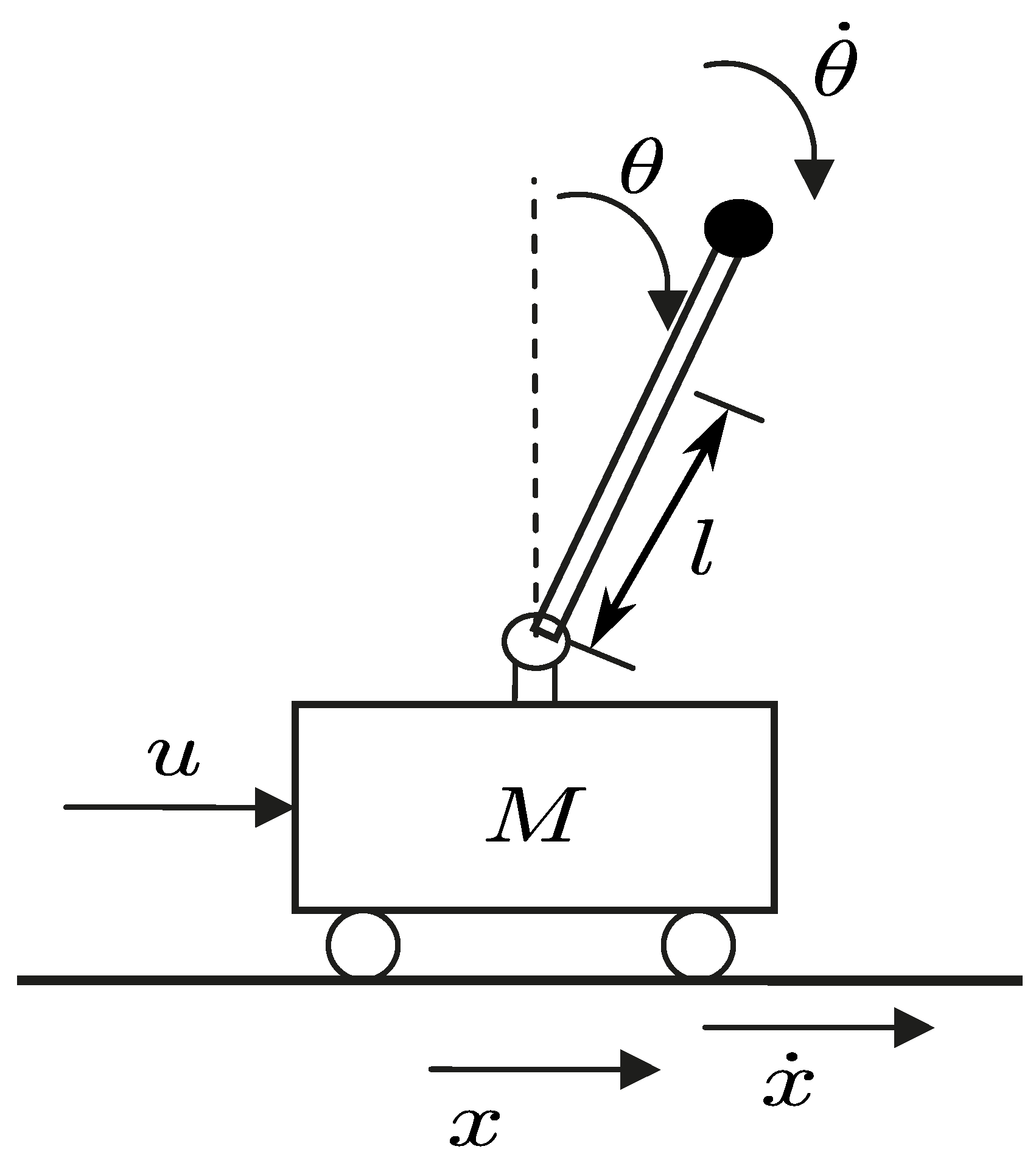
Figure 1. Schematics of the inverted pendulum on a cart.
Applsci 10 06158 g001
Figure 2. Flowchart of the particle swarm optimization (PSO) process.
Applsci 10 06158 g002
Figure 3. Flowchart of the differential evolution (DE) process.
Applsci 10 06158 g003
Figure 4. Flowchart of the firefly algorithm (FFA) process.
Applsci 10 06158 g004
Figure 5. Block diagram of the proposed controller.
Applsci 10 06158 g005
Figure 6. Outline of θ input membership functions.
Applsci 10 06158 g006
Figure 7. Experimental inverted pendulum on a cart.
Applsci 10 06158 g007
Figure 8. Operation outline of the swing-up controller.
Applsci 10 06158 g008
Figure 9. Optimized and not optimized membership functions for each one of the inputs.
Applsci 10 06158 g009
Figure 10. Membership functions plotted together for each input.
Applsci 10 06158 g010
Figure 11. Time response in real-time for the not optimized and optimized controller by PSO.
Applsci 10 06158 g011
Figure 12. Time response in real-time for the not optimized and optimized controller by FFA.
Applsci 10 06158 g012
Figure 13. Time response in real-time for the not optimized and optimized controller by DE.
Applsci 10 06158 g013
Figure 14. Time response in real-time for the Takagi–Sugeno Fuzzy Servo Control (TSFSC) scheme.
Applsci 10 06158 g014
Table 1. Parameters of the input membership functions.
Optimization Algorithm
InputParameterNOT OPT.PSOFFADE
σ Z 0.130.390.410.37
σ P S 0.130.610.730.65
θ σ P B 502.802.442.69
c P S 0.260.881.191.08
c P B 0.41.031.291.18
σ Z 0.070.580.830.59
σ P S 0.070.630.80.65
x σ P B 302.751.942.68
c P S 0.10.480.560.53
c P B 0.30.610.960.63
σ Z 0.650.290.250.37
σ P S 0.650.560.520.56
θ ˙ σ P B 108.526.802.79
c P S 1.300.990.960.93
c P B 21.431.371.2
σ Z 0.40.10.150.1
σ P S 0.40.110.10.1
x ˙ σ P B 612.2412.559.8
c P S 0.50.220.210.2
c P B 0.550.320.330.42
Table 2. Parameters of the experimental inverted pendulum on a cart system.
DescriptionNotationValue
Mass of the cartM 2.024 [kg]
Mass of the pendulumm 0.338 [kg]
Length of the pendulum L p 0.421 [m]
Length of the rail L r 1.43 [m]
Length to the center of mass of the penduluml 0.33 [m]
Moment of InertiaI 0.015 [ kg / m 2 ]
Viscous friction of the pendulum f v θ 0.003 [Nm seg/rad]
Viscous friction of the cart f v x 6.33 [Nm seg/rad]
Coulomb friction of the cart (positive sense) f c x + 28.1 [Nm]
Coulomb friction of the cart (negative sense) f c x 23.2 [Nm]
Gravity accelerationg 9.81 [ m / seg 2 ]
Table 3. Obtained values of the objective function in every optimization stage.
AlgorithmStage 1Stage 2
NOT OPT. 175.939 235.608
FFA 96.835 115.871
DE 96.544 115.741
PSO 96.520 114.916
Table 4. Performance indexes in real-time experimentation.
Algorithm L 2 [ θ ˜ ] [deg] L 2 [ x ˜ ] [m] L 2 [ τ ] [N]
NOT OPT. 1.0360 0.0776 20.4555
DE 0.9765 0.0191 18.9581
FFA 0.9451 0.0193 19.3536
PSO 0.9371 0.0170 18.9549
Table 5. Performance index for T-S fuzzy servo controller with two MFs.
Algorithm L 2 [ θ ˜ ] [deg] L 2 [ x ˜ ] [m] L 2 [ τ ] [N]
TSFSC 4.5969 0.0356 27.0273