1. Introduction
Vertical-cavity surface-emitting lasers (VCSELs) [
1,
2] are nowadays substituting the traditional edge emitting semiconductor lasers (EEL) in many applications, such as Fiber to the Home links, computer networks, optical interconnects, optical sensing, laser printing, etc. The reason lies in their significant advantages, such as low power consumption, small footprint, high reliability, easy packaging, single longitudinal mode emission, high modulation speed, low cost, circular output beam and easy fabrication in two-dimensional arrays. The last couple of years brought a huge deployment of VCSEL for proximity and 3D sensing and autofocus functions in smart phones with overall VCSEL revenue of ∼1.78 billion USD in 2018 and a trend to reach 3.8 billion USD by 2023 [
3]. Short and medium range optical communication links, the very first wide deployment of VCSELs, demand for continuous increase of VCSEL modulation speed [
4]. Consequently, many efforts have been paid to boost the VCSEL direct modulation speed [
5,
6,
7,
8,
9,
10] with continuously increasing the modulation speed up to 71 Gb/s [
11]. Further increase of the VCSEL modulation speed would require abandoning the direct modulation approach and, eventually, integrating VCSEL with an electro-optic modulator [
12,
13]. Recently, an impressive small-signal modulation cut-off frequency of about 30 GHz for such an integrated VCSEL with electro-absorption modulator (EAM), i.e., EAM-VCSEL has been reported [
14]. Separating the functions of the VCSEL as a light source and the EAM as a modulator allows for optimizing each of the two parts of the integrated device with respect to its functions. Electrical optimization of the integrated EAM has been reported in [
15,
16] for a lumped element and traveling electrode design, respectively. Comparison of optimized and experimental characteristics of a stand alone EAM and integrated EAM-VCSEL has been reported in [
13,
14], respectively.
In an EAM-VCSEL, the EAM layer is very thin compared to the EAM section in an edge emitter laser. To obtain enough extinction ratio a resonant structure is needed where the light passes the EAM layer several times. A problem is that a resonant modulator normally gives strong and time varying back reflections that will perturb the carrier density in the VCSEL and hence lead to spurious VCSEL modulation. In this paper we show that it is possible to modulate a resonant EAM without disturbing the amplitude lasing condition of the VCSEL. By careful design, utilizing detuned loading and the chirp factor of the EAM material, one can obtain VCSEL-EAMs with a resonantly enhanced, flat modulation response with ultrahigh bandwidth. We carry out a thorough analysis of the small- and large-signal modulation response of such an integrated EAM-VCSEL based on the coupled-cavity approach as reported in the recent experimental studies [
13,
14]. The paper is organized as follows. In
Section 2, we provide the single-mode rate equations for the EAM-VCSEL and their stead-state solutions. On the base of these equations, we first derive in
Section 3 expressions for the modulation transfer function (MTF) of EAM-VCSEL for small-signal modulation of either the EAM losses or the VCSEL injection current. We then present a number of MTF characteristics of coupled-cavity EAM-VCSEL for three typical cases of strong, intermediate and small coupling strength. These three cases are also considered in
Section 6 where we carry out the large-signal modulation response of EAM-VCSEL. Finally, in
Section 7 we conclude.
2. Single-Mode Rate Equations for EAM-VCSELs
A coupled-cavity VCSEL possesses at least two longitudinal modes that experience a generic mode anticrossing effect as the two cavities are tuned in resonance to each other [
17,
18,
19,
20,
21,
22]. When the two cavities are strongly detuned, the standing wave patterns of these two modes are profoundly different—each of them being mostly concentrated in a separate cavity [
18,
19,
21,
22]. In such a case, only the mode that is situated mostly in the VCSEL cavity providing the gain suffices to be considered as the second one is strongly depressed. Considering such strongly detuned cavities, the single-(composed) mode rate equations for EAM-VCSELs are
for the photon density
and
for the carrier density
n. Here
is light group velocity,
is the variable confinement factor in the VCSEL QW region and
with
and
;
being the gain compression coefficient.
is the total effective cavity loss resulting from both internal losses and radiation losses; it depends on the internal photon distribution in the device and is obtained from the mode solver.
The stationary solution of the above equations is obtained as follows: from Equation (
2)
which replaced in the stationary expression of Equation (
1)
leads to quadratic equation for the photon density
Denoting
, we can rewrite this equation as
with solutions
with
and
.
4. EAM-VCSEL: Structure and Eigenmodes
Details of the EAM-VCSEL structure designed to operate at a wavelength of 850 nm are listed in
Table 1. We based our choice of the structure on the recently reported experimental GaAs/AlGaAs EAM-VCSEL [
13] with enhanced modulation bandwidth [
14]. In order to make the comparison with more elaborated numerical approach [
23], some details as grading layers in the DBRs and the cavity cladding layers are replaced by average refractive index uniform layers and EAM and VCSEL quantum well (QW) and barrier regions are lumped in single uniform layers. We calculate the EAM-VCSEL eigenmodes following the transfer matrix method and imposing the condition that there is no in-coming field to the whole multilayer structure as outlined in [
21,
24]. However, when considering EAM-VCSEL it is important to take into account the refractive index changes with carrier density in the QW region of the VCSEL cavity and the one of the EAM QW region with
, i.e., the linewidth enhancement factors
and
[
23]. The refractive index change
in the QW regions of the VCSEL when changing carrier density by
is
We consider that
starts changing as soon as
. The eigenmode and steady-state carrier density calculations are done repeatedly updating QW refractive index accordingly to Equation (
22) until
.
The change of the real part of the refractive index of the EAM QW region is given by
Here, the EAM cavity thickness is taking three values in order to treat the representative cases of strong (m), moderate (m) and weak (m) coupling between the EAM and the VCSEL cavities.
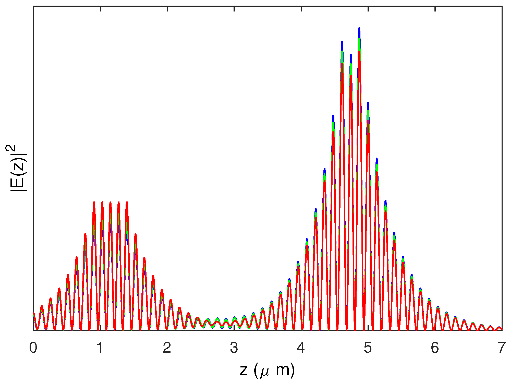
We illustrate the importance of considering the linewidth enhancement factors in
Figure 1 where we present the optical power distributions along the EAM-VCSEL obtained in a similar way as in [
21,
24] for strong coupling between the VCSEL and the EAM cavity and
. The blue curves correspond to the case when the refractive indices of both VCSEL and EAM QW regions are constant, i.e.,
. When only the VCSEL active region antiguiding effect is taken into account, i.e.,
(green curve), the coupling between the two cavities improves. It also further improves when both linewidth enhancement factors are accounted for—red curve for
.
In order to self-consistently calculate the impact of antiguiding effect in the VCSEL active region, we consider typical VCSEL parameters for the steady-state solution of EAM-VCSEL rate in Equations (
10) and (
11), as listed in
Table 2.
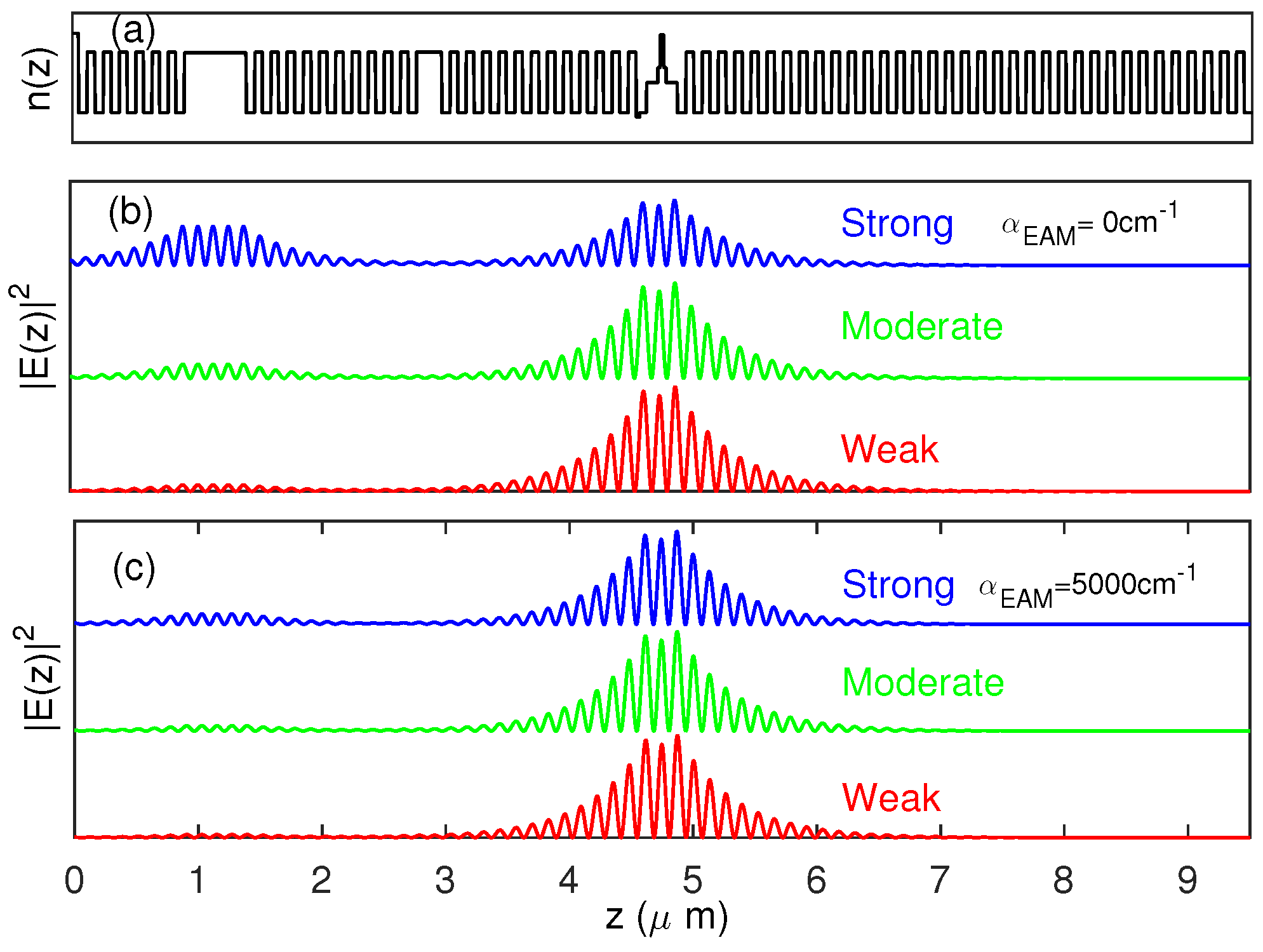
In
Figure 2, we present the optical power distributions along the EAM-VCSEL for the composed cavity mode situated primary in the VCSEL cavity for these three cases and
,
. The coupling between the EAM and VCSEL cavities is determined by their relative optical thicknesses as demonstrated in [
21,
24]. It is the strongest at the designed wavelength when both cavities optical thicknesses are integer numbers of
. Increasing
, the EAM cavity is tuned out of resonance with the VCSEL cavity, the optical field distribution becoming more asymmetric and concentrated into the VCSEL cavity—c.f. the blue, green and red curves in
Figure 2b. The result is an increased (decreased) confinement factor in the VCSEL (EAM) QWs similarly to [
21]. Increasing the EAM absorption plays a similar role as increasing the detuning between the cavities (c.f. the similar optical power distribution for the detuned case without absorption in
Figure 2b and the resonance case with large
in
Figure 2c).
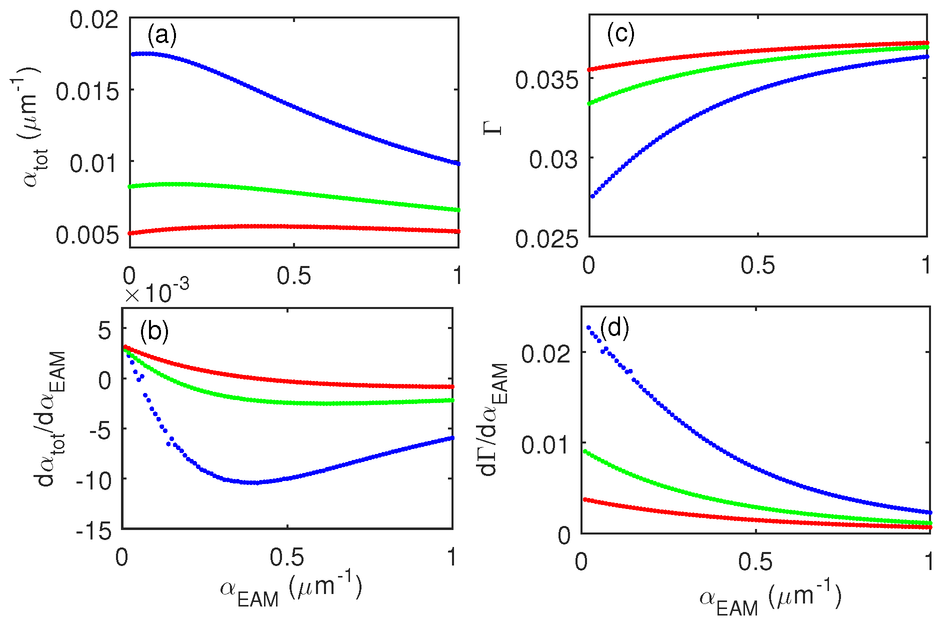
The relevant quantities for the small-signal response Equation (
14) are the derivatives
and
. Repeating the eigenmode calculations when varying the absorption coefficient
in the EAM QW layer, we obtain the dependence of the total absorption
of the EAM-VCSEL and the VCSEL cavity confinement factor
on the EAM absorption
as shown in
Figure 3. As can be seen from this figure, for the strongly and moderately coupled cases (blue and green curves)
and
and their derivatives are strongly nonlinear with
. Therefore, we draw the conclusion that the weak coupling case is best suited for loss modulation of the EAM-VCSEL as the device total absorption and VCSEL confinement factor are much less dependent on
.
5. Results on Small-Signal Modulation Response of EAM-VCSELs
Figure 4 presents the EAM-VCSEL small-signal modulation response for the case of strong coupling between the EAM and the VCSEL cavities.
Figure 4a represents the VCSEL current modulation case, i.e.,
from Equation (
21) and
Figure 5b represents the loss modulation case, i.e.,
from Equation (
18). Different colors correspond to different bias points for the EAM losses as denoted in the figure caption. From
Figure 4a we see that the modulation cut-off frequency for current modulation strongly improves as the bias absorption of the EAM is increased: from 13.5 GHz for
(black curve) to 24 GHz for
(red curve). This is due to the fact that as
is increased, the optical power distribution along the EAM-VCSEL is modified: it is decreased (increased) in the EAM (VCSEL) cavity. Consequently, the confinement factor in the VCSEL cavity and photon density are increased. However, one remains limited by the relaxation oscillation frequency. For the case of small-signal modulation of EAM losses shown in
Figure 4b, the relaxation frequency peak is still well pronounced, however its amplitude strongly decreases with
and the modulation curve is flatter compared to the current modulation case. Consequently, the cut-off frequency is considerably increased, up to about 45 GHz for
(black curves) and beyond 100 GHz for
(all other curves). This, together with the conclusions drawn when comparing the optical power distribution for strong and moderate coupling with and without absorption in the EAM, leads to the expectation that such a high cut-off frequency should be easily achieved for the cases of moderate and weak coupling.
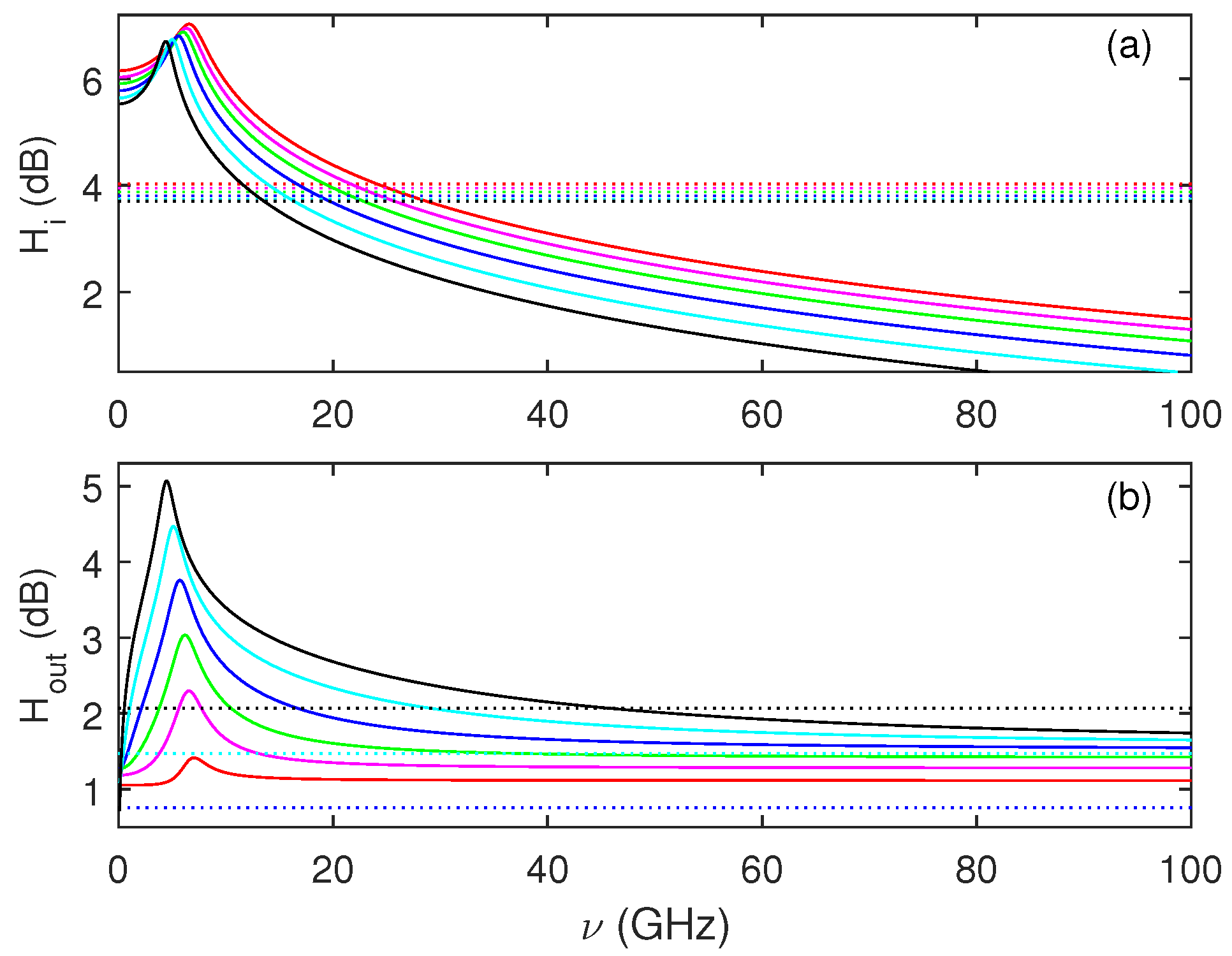
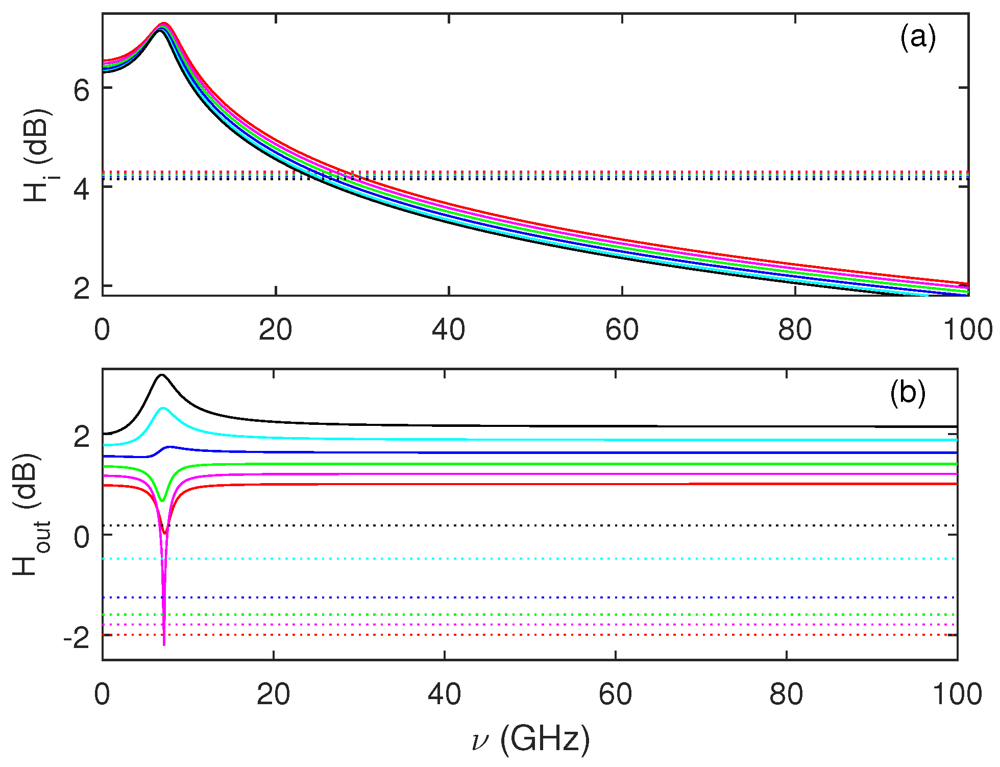
Figure 5 presents the EAM-VCSEL small-signal modulation response for the case of moderate coupling between the EAM and the VCSEL cavities.
Figure 5a represents the VCSEL current modulation case and
Figure 5b—the losses modulation case. Different colors correspond to different bias points for the EAM losses in the same way as for
Figure 4. From
Figure 5a we see that the modulation cut-off frequency for current modulation is much less influenced as compared to the case of strong coupling (increasing from about 25 GHz to 28 GHz) as the bias absorption of the EAM is increased. This is due to the fact that the changes of
now impact much less the optical power distribution along the EAM-VCSEL and, consequently, the confinement factor in the VCSEL cavity and photon density. For VCSEL current modulation, the cut-off frequency remains limited by the relaxation oscillation frequency. For the case of small-signal modulation of EAM losses shown in
Figure 5b, the cut-off frequency remains beyond 100 GHz for all the cases of different
considered, except for the magenta curve for
. The modulation curve is quite flat with features only around the relaxation oscillation frequency. Moreover, the shape of these features considerably depends on the bias
; while it has a well pronounced maximum, for small
(black and cyan curves), it flattens, transits a region of both maximum and minimum (
, blue curve) and then remains a sharp minimum only (green, magenta and red curves)). Such profound change of the shape of the modulation curve has been indeed found experimentally in [
14] but remained unexplained. Our results therefore, not only provide an explanation for the change of the shape of the modulation curve but give the insight that the high frequency cut-off of about 30 GHz for the EAM-VCSEL structure investigated in [
14] is due to electrical parasitics limitation.
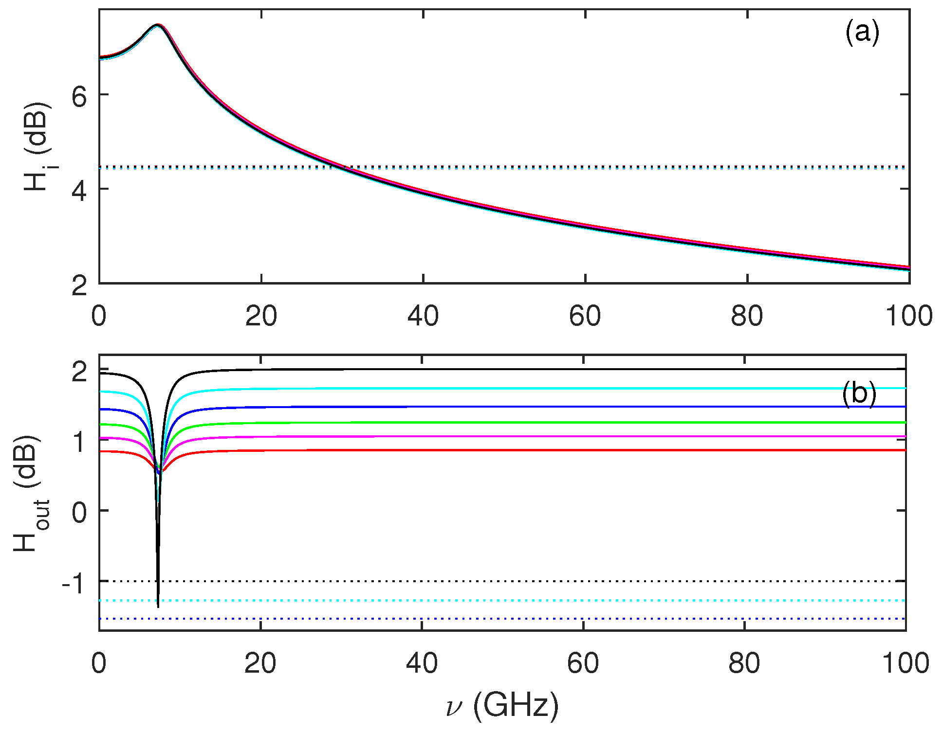
Finally,
Figure 6 presents the EAM-VCSEL small-signal modulation response for the case of weak coupling between the EAM and the VCSEL cavities. The tendencies observed for the previous two cases remain the same. From
Figure 6a we see that the modulation cut-off frequency for current modulation is now hardly influenced by the bias EAM absorption and modulation curves for loss modulation becomes quite flat and displays only a minimum at the relaxation oscillation frequency which becomes very shallow with increased EAM absorption. The quite flat response of the modulation curves for different biased
indicates to the possibility to realize a large-signal modulation response beyond 100 GHz, which we investigate in the next section.
It is worthy to note that in our way of calculations we consider that the optical field reaches its steady-state distribution on a time scale that is much shorter than the rest of the time scales (carrier dynamics and electro-optical modulation). This consideration is justified as the coupled-cavity VCSEL is very short ( length scale) and, therefore, the roundtrip time is also very short ( time scale). Furthermore, there is no significant change of the optical field distribution during modulation and therefore, not many roundtrips are necessary for reaching optical field steady state.
6. Large-Signal Modulation Response of EAM-VCSEL
Large-signal modulation response of EAM-VCSEL is investigated by integrating numerically the single mode rate equation for the normalized electric field, i.e.,
together with the Equation (
2) for the carrier density
n, and supplemented by a third equation for the electrical response of the EAM modulator as an RC circuit, namely
We consider for the time-constant
ns which provides an electrical cut-off frequency of 300 GHz. Here,
is the modulation signal applied to the EAM and is taken as a random sequence of not-return-to zero bits of length
. In order not to recalculate the optical field distribution at each step of integration, we approximate the dependencies of the total absorption
of the EAM-VCSEL and the VCSEL cavity confinement factor
on the EAM absorption
(c.f.
Figure 3) by a third order polynomial.
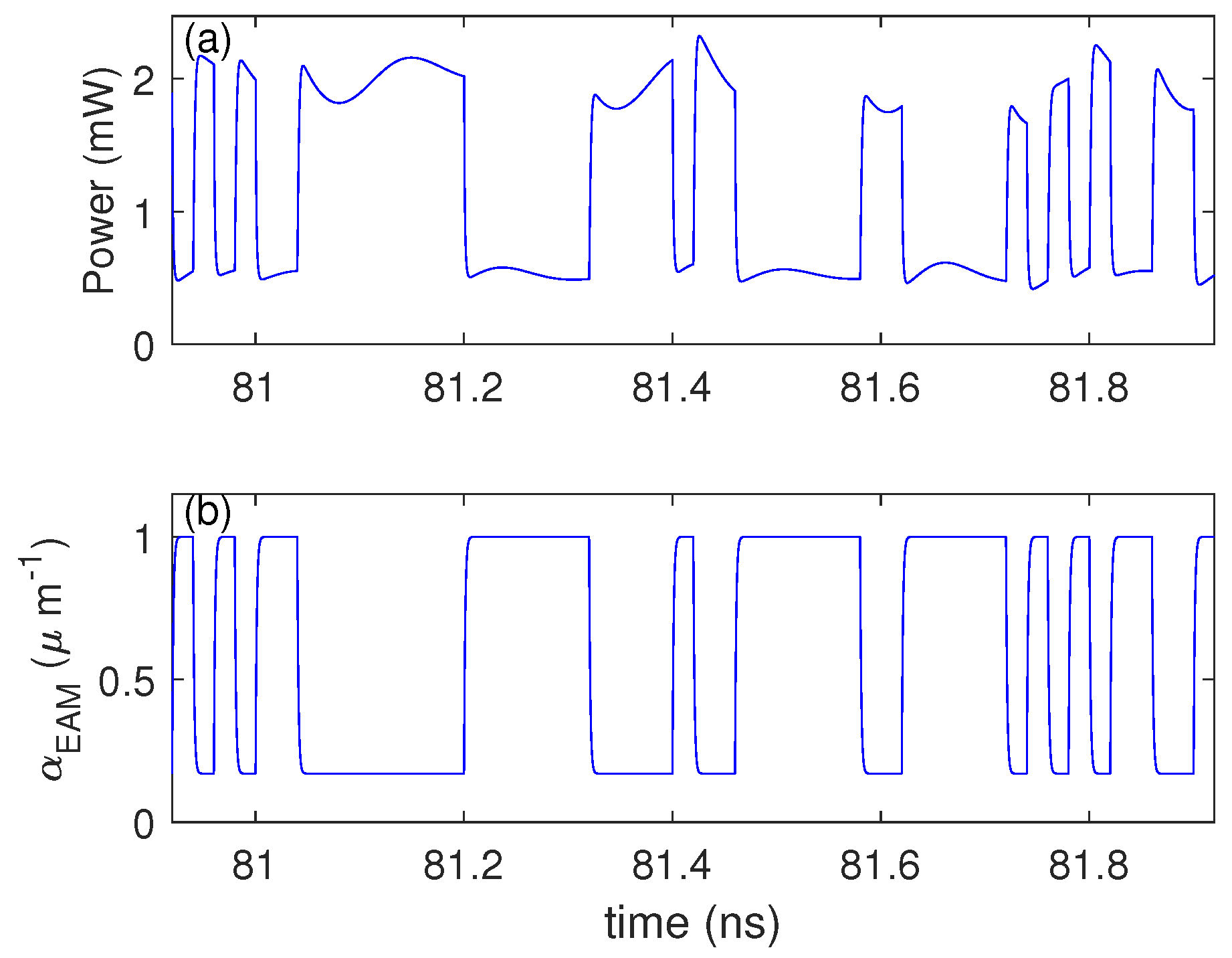
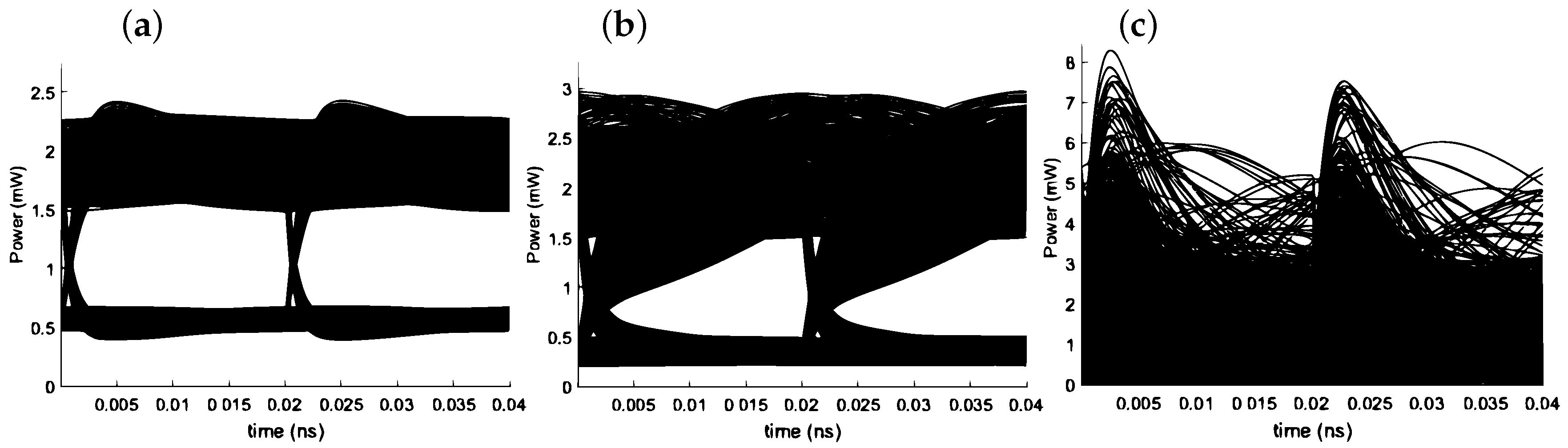
Figure 7 presents the time traces of the output power (a) and
(b) for digital, non-return-to-zero modulation at 100 Gb/s of an EAM-VCSEL with
displaying that the output power manages to well follow the modulation signal of
. Therefore, a well opened eye diagram is observed for this EAM cavity length—see
Figure 8a. However, the eye becomes closed for shorter and longer EAM cavities—see
Figure 8b,c. Carrier dynamics in the EAM section play an important role for the ultra-high-speed operation of EAM-VCSEL. Considering the very small length of the EAM cavity, a 1 ps carrier sweep rate of order of
m/s would suffice. The reverse bias of the EAM section will also contribute to significantly increasing the sweep rate of optically generated carriers [
25].
7. Conclusions
We consider an integrated electro-absorption modulator within a coupled-cavity VCSEL structure (EAM-VCSEL) and demonstrate that it is possible to modulate the output light power at frequencies as high as 100 GHz by modulating the EAM voltage. Such an ultrahigh bandwidth modulation can be achieved by a careful design, utilizing detuned loading and the chirp factor of the EAM material in order not to disturb the amplitude lasing condition of the VCSEL. We derive expressions for the modulation transfer function (MTF) of the EAM-VCSEL for small-signal modulation of either the EAM losses or the VCSEL injection current. We present a number of MTF characteristics for three typical cases of strong, intermediate and small coupling strength. These three cases are also considered when carrying out the large-signal modulation response of the EAM-VCSEL and a clear open-eye diagram is demonstrated at 100 Gbs for an optimal EAM cavity length.
On the base of our analysis, we conclude that it is not only the coupling strength between the VCSEL and EAM cavities that is important but also the refractive index induced effect in the EAM cavity. Therefore, an optimal EAM cavity length exists when modulating the EAM absorption in order to obtain best modulation. Ideally, for an optimized EAM-VCSEL design, the photon density in active section will not vary as the EAM losses are modulated. The field inside the active layer will then be purely frequency modulated. In addition, the field from the bottom of the VCSEL will exhibit flat frequency modulation without any residual amplitude modulation. Only the field from the top will exhibit amplitude modulation due to the EAM loss modulation and the frequency-to-amplitude nodulation conversion caused by the detuned loading during output coupling, i.e., the wavelength dependence of the EAM output mirror transmittivity.


