Article

Flexural Performance of Novel Nail-Cross-Laminated Timber Composite Panels

1
Department of Civil and Environmental Engineering, Western University, London, ON N6A 5B9, Canada
2
School of Civil Engineering, Shenyang Jianzhu University, Shenyang 110168, China
*
Author to whom correspondence should be addressed.
Appl. Sci. 2020, 10(17), 5983; https://doi.org/10.3390/app10175983
Submission received: 11 June 2020 / Revised: 6 August 2020 / Accepted: 25 August 2020 / Published: 29 August 2020
(This article belongs to the Special Issue 10th Anniversary of Applied Sciences: Invited Papers in Materials)

Abstract

:
Cross-laminated timber (CLT) is an innovative wood panel composite that has been attracting growing interest worldwide. Apart from its economic benefits, CLT takes full advantage of both the tensile strength parallel to the wood grain and its compressive strength perpendicular to the grain, which enhances the load bearing capacity of the composite. However, traditional CLT panels are made with glue, which can expire and lose effectiveness over time, compromising the CLT panel mechanical strength. To mitigate such shortcomings of conventional CLT panels, we pioneer herein nail-cross-laminated timber (NCLT) panels with more reliable connection system. This study investigates the flexural performance of NCLT panels made with different types of nails and explores the effects of key design parameters including the nail incidence angle, nail type, total number of nails, and number of layers. Results show that NCLT panels have better flexural performance than traditional CLT panels. The failure mode of NCLT panels depends on the nail angle, nail type, and quantity of nails. A modified formula for predicting the flexural bearing capacity of NCLT panels was proposed and proven accurate. The findings could blaze the trail for potential applications of NCLT panels as a sustainable and resilient construction composite for lightweight structures.

1. Introduction

Cross-laminated timber (CLT) is a wood panel product made by gluing layers of solid wood together. Each layer is orientated perpendicular to adjacent layers and glued on the wide faces of each panel, usually in a symmetric scheme so that the outer layers have the same orientation [1]. Regular timber is an anisotropic material with physical properties depending on the direction at which a force is applied [2]. By gluing layers of wood at perpendicular angles, the panel can achieve structural rigidity in both directions. CLT panels are distinct to glued laminated timber, a product having all laminations orientated in the same direction [3]. Because of its structural properties, ease of prefabrication and lightweight compared with other construction materials, CLT panels have gained wide use in high-rise buildings [4].
CLT panels were first developed in Europe, then quickly promoted in other countries. Several studies on CLT panels have been conducted in Canada, Finland, the United States, Germany, and other countries [5,6]. Moreover, CLT panels have been used in diverse projects, which greatly stimulated further development of this industry. Amini et al. [7] studied the application of CLT panels in shear wall systems and proposed factors that affect its performance. Mayencourt and Mueller [8] introduced the unidirectional bending state of CLT panels and proposed a structural optimization scheme. He et al. [9] further studied cross-laminated timber panels under bending and compression. Their results showed that the bending stiffness and ultimate load resisting capacity of CLT panels can be predicted by numerical models.
CLT panels have numerous advantages, making it attractive as a building material [10,11,12]. This includes design flexibility since they can be applied in walls, roofs, ceilings, etc. The thickness of the panels can easily be increased by adding more layers, and the length of the panels can be augmented by joining panels together. Other benefits include eco-friendliness, prefabrication, and thermal insulation. Yet, CLT panels have shortcomings including: (i) most glues are susceptible to environmental exposures, which compromises service life [13]; (ii) large amounts of glue are used, causing environmental pollution [14].
Therefore, Nail-Cross-Laminated Timber (NCLT) panels are proposed in this study as an alternative. Compared to CLT panels, NCLT panels have numerous benefits including: (i) longer service life; (ii) high yield; (iii) pipelines can be integrated; (iv) superior recovery ability after large deformation; and (v) NCLT panels can be used with many cavities, which requires less raw materials [15]. Several studies have previously shown that steel-CLT composite connection panels have good connection properties and long service life in buildings [15,16]. The orthogonal staggered laminated staple structure of the glulam-CLT shear connections with double-sided punched metal panel improved the shear load carrying capacity [17,18]. There are still no detailed experimental studies in the open literature to demonstrate this concept. Moreover, there is no analysis or discussion on the extent to which different nails and other design parameters affect the NCLT panel structural performance.
Accordingly, the present study reports experimental results of six groups of NCLT panels subjected to four-point load bending. The flexural performance of the NCLT panels was discussed, and the effects of influential parameters including the nail incidence angle, nail type, total number of nails, and number of layers have been explored, discussed, and analyzed. Based on the test results, a modified formula for predicting the flexural bearing capacity of NCLT panels was proposed and proven accurate. This work could blaze the trail for future research on NCTL panels and its introduction in building codes and full-scale construction.

2. Experimental Program

2.1. Test Specimens

Six groups of specimens were investigated in this flexural test. All specimens were made of Canadian SPF (including spruce, pine, and fir), namely spruce-pine-hemlock mixed standard material. All specimens were connected by nails. The details of the test specimens are outlined in Table 1. The material properties of the wood used in this test are summarized in Table 2. Vertically and horizontally textured solid wood panels were interlaced orthogonally to each other, thus forming the new NCLT panels. Vertically textured solid wood panels were 2350 mm in length and 235 mm in width with 38 mm thickness. The horizontally textured solid wood panels were 705 mm in length, 235 mm in width, and 38 mm in thickness. The 3-layer and 5-layer NCLT panels were nailed from bottom to top, that is, the nail was nailed from the bottom layer to the first layer. When the nailing angle was 0°, the nail gun was positioned perpendicular to the surface of the nail panels. When the nail was shot at 30°, an auxiliary nailing bracket was used. Figure 1a–d and Figure 2a–e show partial detail views of the longitudinal section of each set of test specimens and a partial detail of the top view. In the 5-layer CLT panel structure, the arrangement of nails between the first and second layers was the same as the one between the third and fourth layers, as shown in Figure 2d. The nail arrangement between the second and third layers was the same as that between the fourth and fifth layers, as shown in Figure 2e.

2.2. Test Setup and Experimental Procedures

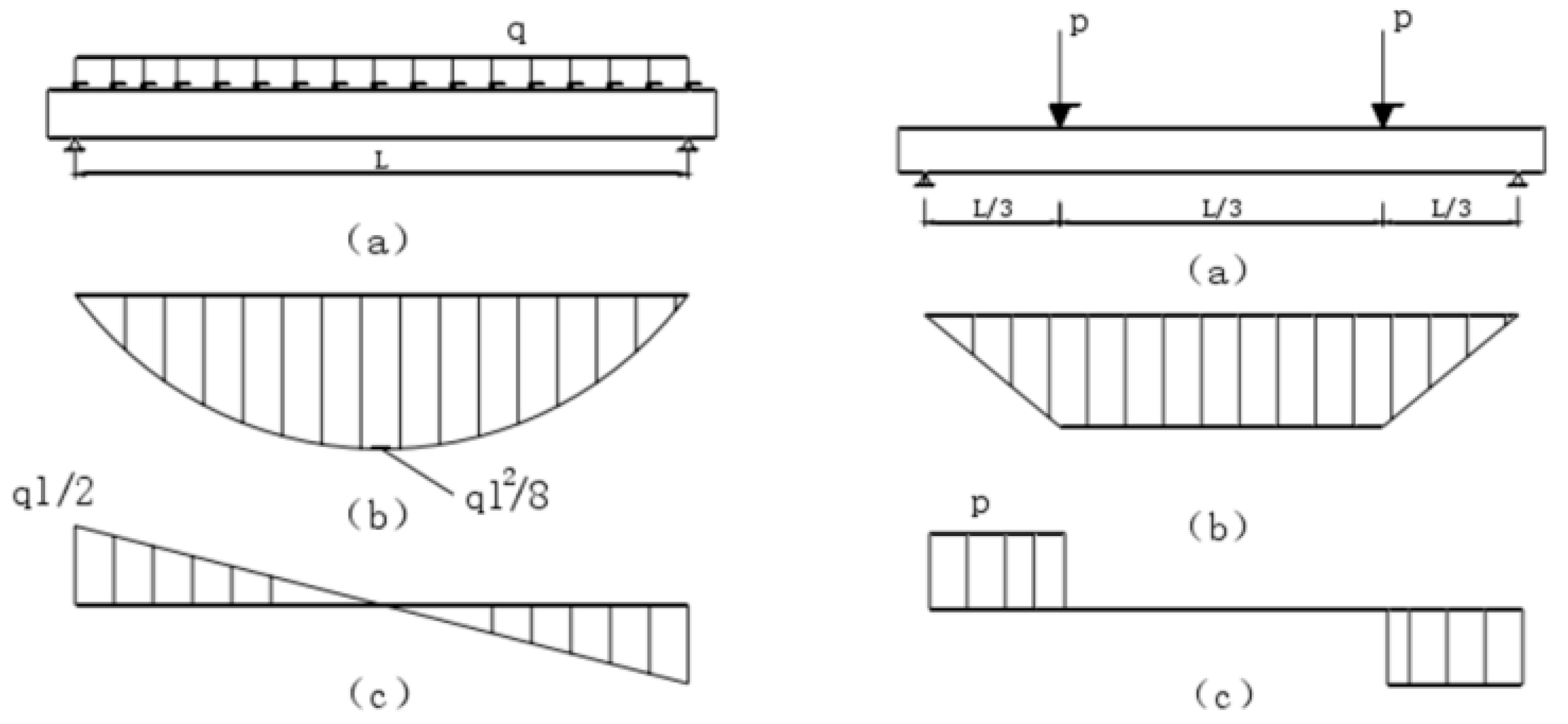
The bending behavior was investigated using the four-point loading method. The different stress states of pure bending and bending shear zones are shown in Figure 3a–c. During the test, the displacement of each section of the specimen was measured by linear variable displacement transducers (LVDTs) of different ranges, arranged as per the scheme shown in Figure 4. Large displacement gauges were required at mid span since wood is an elastic-plastic material that can undergo considerable deformation. Since vertical displacement at both specimen’s ends near the support is small, small-range LVDTs were selected. Strain gauges were attached at the lower surface at mid-span, one-third, two-thirds, quarter, and three-quarters of the section and staggered at the centerline on both sides of the specimen, as shown in Figure 5. The various strain gauges on the lower surface were labelled as illustrated in Figure 5a. The strain gauges on both sides were sequentially numbered from top to bottom and left to right, i.e., from C1 to C10. Strain gauges were also mounted on the side of the 3-layer panel and the 5-layer panel, as shown in Figure 5b,c.
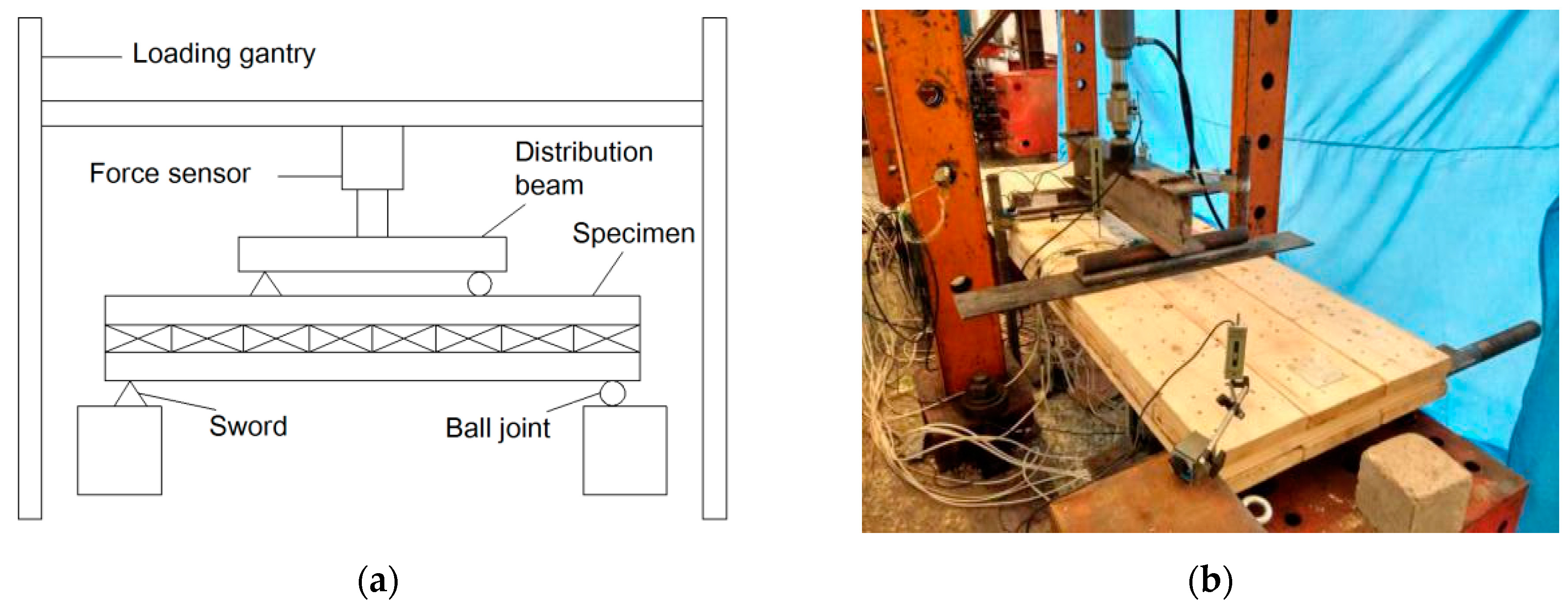
The test was carried out under four-point loading, and the specimen was loaded via an I-beam. To prevent local shear failure, a steel support panel was placed at the loading point to strengthen the load contact area. The total weight of the I-beam, support, and steel panel (220 kg) were converted to a preload. The load was held for 3 min to check whether all strain and displacement gauges functioned properly. Each level of load was incrementally increased by 2 kN, and the load at each stage was maintained for 3 min. Data were recorded using a data acquisition system until specimen failure. The loading set-up is shown in Figure 6a,b.

3. Experimental Results and Analysis

3.1. General Behavior

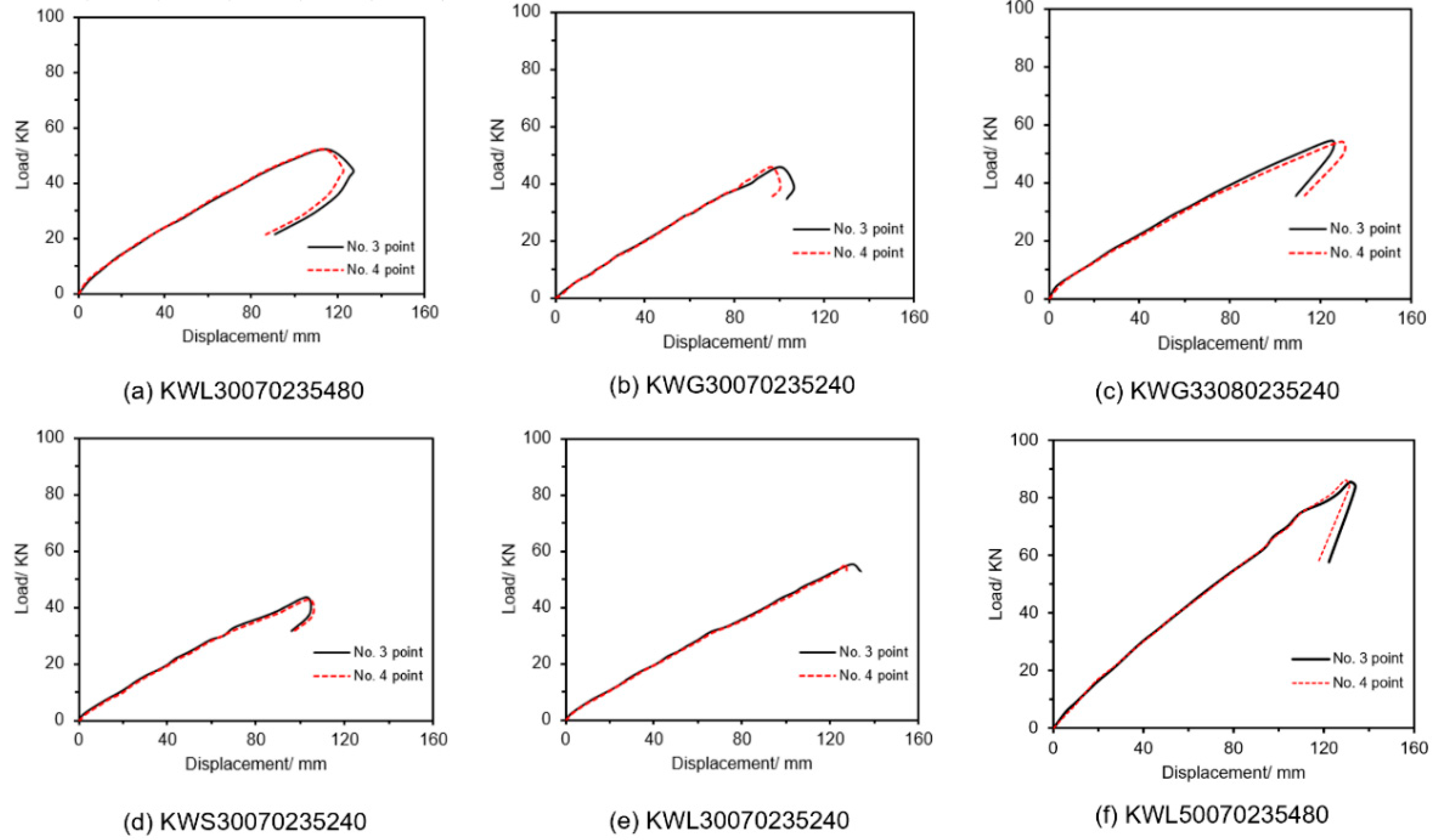
During the initial stage of loading, the NCLT panels were in the elastic stage, and the specimen occasionally emitted slight sound. When the load was about 30 kN, the specimen started to emit continuous soft sound, and the average mid-span displacement reached 50–60 mm. In the later stage of loading, the specimen entered the plastic deformation phase with significantly larger deformation and continuous fracture sound. The bottom tensile side of the pure bending part of the specimen also began to emit wood powder, indicating that wood fibers were continuously braking. When the specimen reached its limit load bearing value, the veneer at the bottom tension zone was suddenly pulled off and lifted, emitting a loud breaking sound. At this stage, the bearing capacity of the CLT panels sharply decreased, and specimens became ductile. Load-displacement curves of the six panels are shown in Figure 7a–f. Values of mid-span displacement and the corresponding ultimate bearing capacity results are summarized in Table 3.

3.2. Load Resistance and Failure Modes

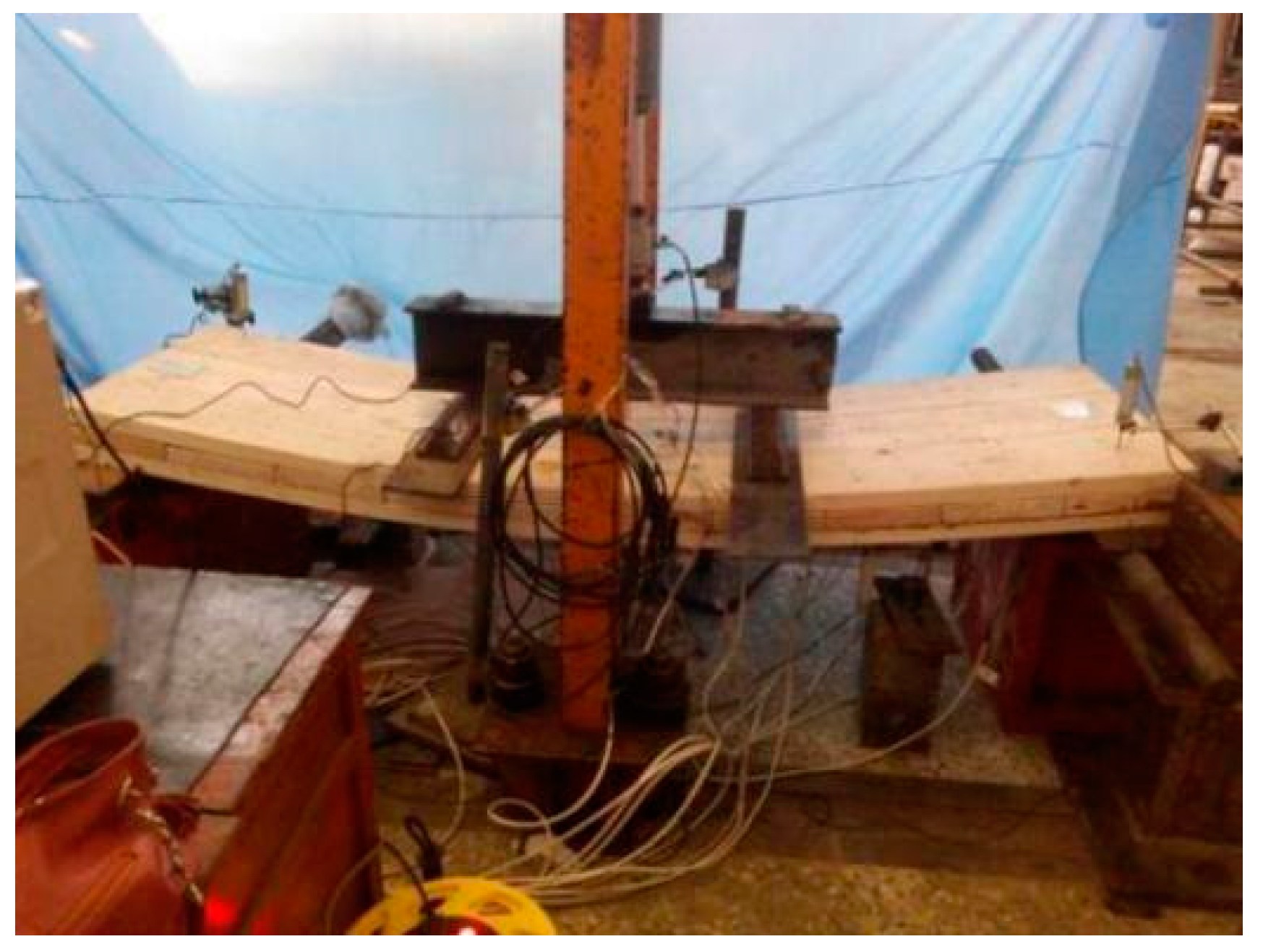
Typical deformation of a NCLT test specimen is shown in Figure 8. The mid-span displacement of specimen 2 was the smallest, yet exceeded 100 mm; specimen 5 had the largest displacement at mid-span, exceeding 130 mm, far beyond the floor deformation limit of L/200 according to the Chinese Standard GB 50010-2002 [19] under normal use conditions, indicating that NCLT panels have very large deformation capacity. The failure mode of specimens was primarily through tensile failure of the panel in the extreme tension zone, while the horizontally pressed wooden panels did not undergo failure. The test specimens exhibited overall ductile behavior. Damage of specimens originated from weak links in the tension zone, such as wood knots and defects, which caused stress concentration, leading to crack initiation and growth. Such cracks further developed into diagonal shape, which eventually caused the veneer to be broken. Some specimens warped in the width direction during processing, which resulted in larger gap between plates. As a result, the depth at which the nails were nailed into the wood decreased, and the nail force between the layers weakened. It was also observed that threaded nails in NCLT panels pulled out. Damage then occurred right at the part where the nails were pulled out, indicating that the pullout force of the threaded nails needed to be strengthened, for instance by increasing the nail diameter. When using veneers, previous experience with conventional CLT panels showed that they exhibited slippage and rolling shear. However, NCLT panels in this study experienced no slippage or rolling shear, demonstrating that the interlaminar combination and integrity can be largely improved by using nail connections rather than glue.

3.3. Effects of Different Panel Design Parameters

3.3.1. Effect of Nailing Angle

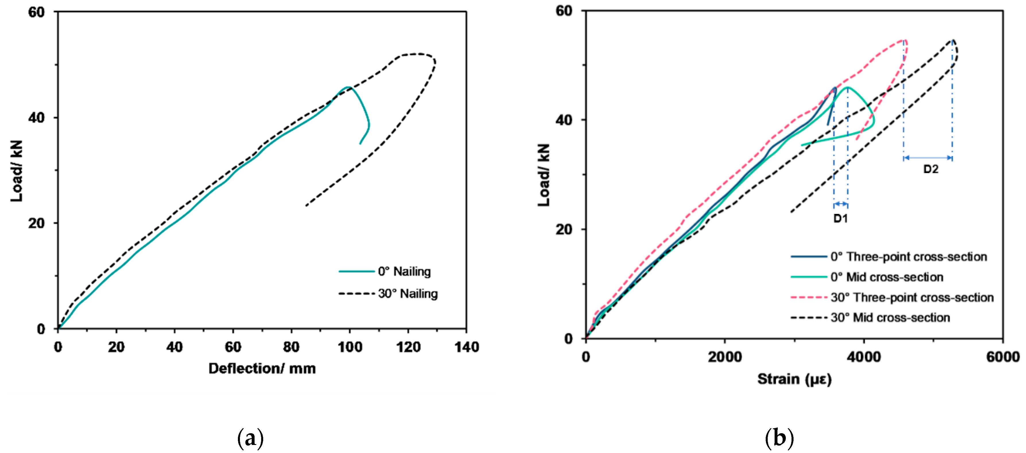
Specimens KWG30070235240 and KWG33080235240 were used as comparative test specimens to explore the effect of the nailing angle, as shown in Figure 9a,b. From analysis of the failure mode, the NCLT panels having 0° nailing angle incurred more serious damage than that of NCLT panels with 30° nailing angle. The 30° nailing could better bite the vertically and horizontally textured solid wood panels, which limited cocking of the wood slabs during the progress of damage. It also limited the development of rupture cracks along the slanting direction, maximizing structural integrity of the NCLT panels. From Figure 9a,b, the ultimate bending moment capacity increased by 18.8% when testing specimen KWG33080235240. In addition, the maximum displacement at mid-span increased by 22.8%, and the ultimate bearing capacity and mid-span displacement were significantly improved, indicating that 30° nailing could indeed improve the bending resistance of NCLT panels. The slatted wood at the bottom tension zone was deformed faster than that of the 0° NCLT panels when deploying 30° nailing, and the difference of strain in the pure bending and bending–shear zone increased with loading. This caused the wood in the bottom tension zone to deform at a faster rate, which was detrimental to the wood material.

3.3.2. Effect of Nail Type

Test specimens KWG30070235240, KWS30070235240, and KWL30070235240 were used for comparison of the effect of the nail type. It can be deduced from Table 4 that the ultimate bearing capacity, deflection, and strain of the threaded nail NCLT panels were the largest, followed by the polished rod NCLT panels, then the screw NCLT panels. From morphological analysis, the polished rod NCLT panels incurred the most serious damage, followed by the screw NCLT panels, then the threaded nail NCLT panels. Accordingly, the threaded nails seemed to be most beneficial at improving the bending resistance of the NCLT panels; the strong pullout force of the threaded nails could prevent cracks from developing from the outside towards the inside, thereby protecting the inside structure and preventing panels from being completely bent and broken.
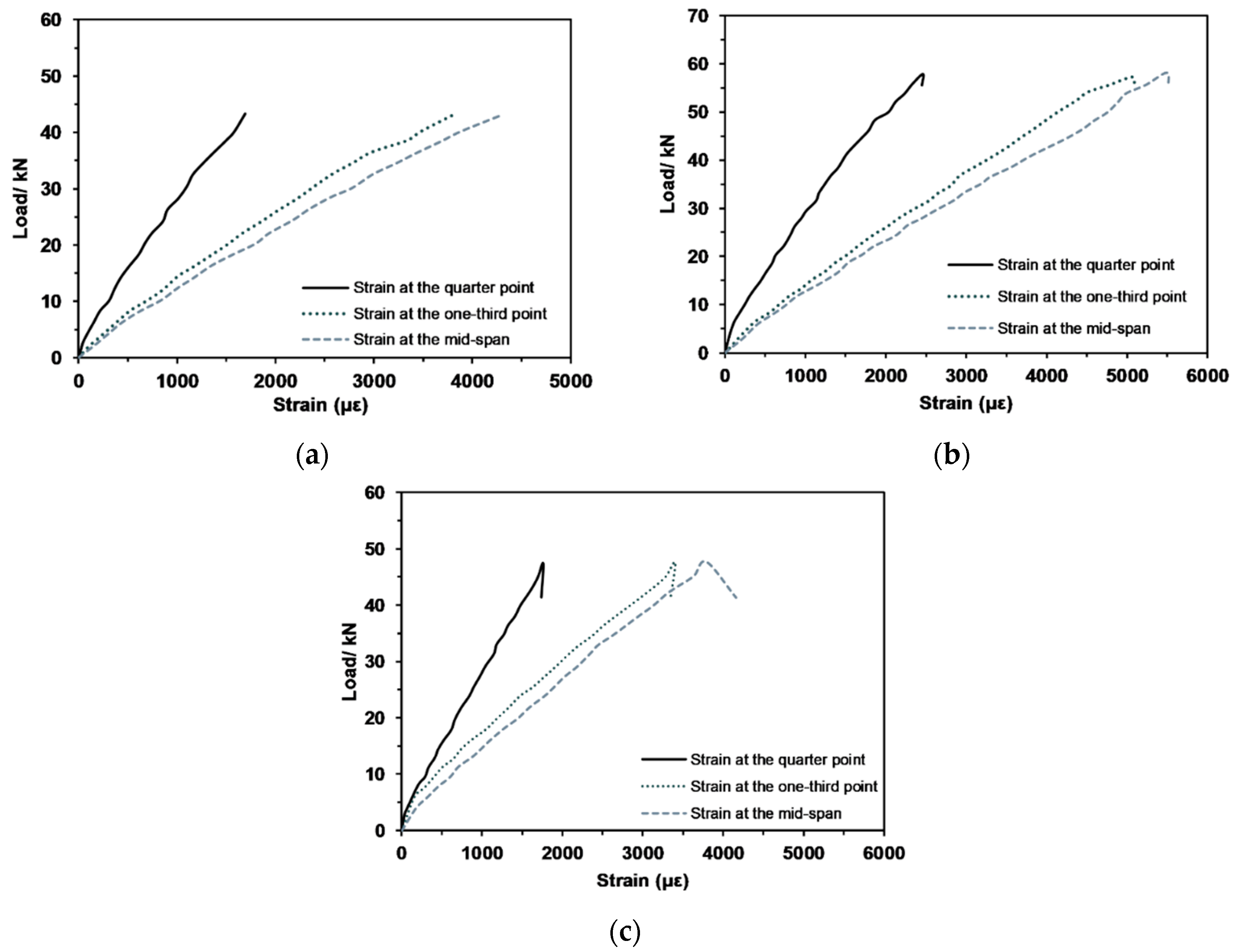
According to the Canadian CLT handbook [20], the actual experimentally measured ultimate bearing capacities of the three types of NCLT panels were greater than the corresponding theoretically calculated values expected for conventional CLT panels, indicating advantages of the nailing method versus using glue. The ultimate bearing capacities of the three types of panels were 47.96 kN for polished rod NCLT panels, 58.46 kN for the threaded nail NCLT panels, and 45.46 kN for the screw NCLT panels. The threaded nail NCLT panels achieved best bending resistance. As shown in Figure 10a,b, the three types of NCLT panels (KWG30070235240, KWS30070235240, and KWL30070235240) displayed superior ductility and large deformation capacity. While threaded nails appeared to be most beneficial for increasing the deflection of the NCLT panels, under similar load, strains of the three NCLT panels were rather comparable, indicating that the type of nail had little effect on strain of the NCLT panels. Generally, the load versus deformation of NCLT panels exhibited desirable linear elastic relationship under normal use (Figure 11a–c).

3.3.3. Effect of Number of Nails

Specimens KWL30070235480 and KWL30070235240 were used to investigate the effect of the number of nails. As the number of nails doubled, the ultimate bearing capacity, ultimate bending moment, and maximum displacement at mid-span decreased by 6%, 5.8%, and 5%, respectively. From Figure 12a, the maximum displacement of specimen KWL30070235240 with 240 nails was 130.69 mm. The maximum displacement of specimen KWL30070235480 with 480 nails was 124.09 mm. An increase of the number of nails could effectively reduce deformation under same load of the NCLT panels. From the analysis in Figure 12b, Strain in the tension zone of the specimen KWL30070235480 was lower than that of specimen KWL30070235240 under similar load at both mid-span section and one-third section. This indicates that an increase in the number of nails improved the interlaminar force of NCLT panels, making their composite behavior more effective. Therefore, the integrity of NCLT panels was consequently enhanced, which is advantageous for maintaining their effective bending rigidity.

3.3.4. Effect of Number of Nailed Layers

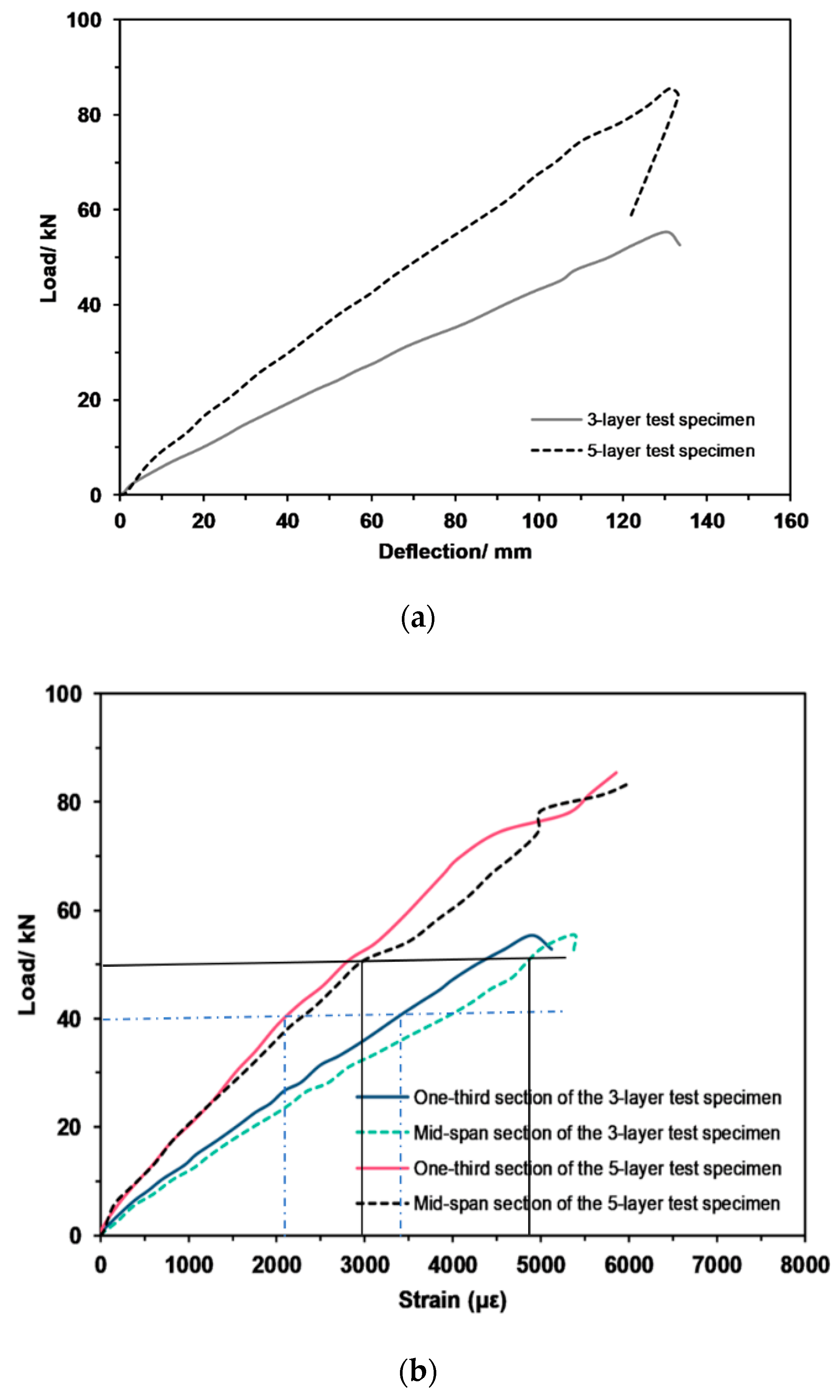
Specimens KWL30070235240 and KWL50070235480 were used to examine the influence of the number of nailed layers. When the number of nailed layers increased by two, the ultimate bearing capacity of the NCLT panels increased by 55.3%, and the ultimate bending moment increased by 55.2%. In addition, the maximum displacement at mid-span slightly increased by 1.2%. It can be deduced from the aforementioned results that increasing the number of nailed layers can greatly improve the load resistance of NCLT panels. According to Figure 13a, the maximum displacement of the 3-layer NCLT panels was 130.69 mm, while that of the 5-layer NCLT panels was 132.47 mm. The effective bending stiffness also increased when the number of nailed layers increased. Strain of the 5-layer NCLT panels was significantly smaller than that of the 3-layer panels (Figure 13b). This implies that the increase in number of nailed layers improved the overall rigidity of the NCLT panels and decreased the deformation rate in the bottom tension zone.

3.4. Ultimate Bending Capacity

FP Innovation theory system refers to the simplified theoretical analysis of conventional CLT panels of Canada’s FP Innovation: mechanical connection theory and combined K-factor theory [20]. Mechanical connection theory and European standard “Eurocode 5” [21] were combined, thus the maximum bending stress in the CLT panels can be considered as:
σ m a x =   σ g l o b a l +   σ l o c a l
σ g l o b a l is the overall stress and can be calculated by Equation (2):
σ g l o b a l = γ 1 E 1 a 1 M ( E I ) e f f
σ l o c a l is the local stress and can be calculated by Equation (3):
σ l o c a l = 0.5 E 1 h 1 M ( E I ) e f f
In Equations (2) and (3): γ is the connection coefficient (0 < γ ≤ 1); a1 is the distance between the center of the first layer and the neutral axis of the CLT panels; and h1 is the thickness of the first layer of slatted wood. From Equations (1) to (3), we can get:
σ = M E 1 ( E I ) e f f ( γ 1 a 1 + 0.5 h 1 ) m a x
If the material of each layer is the same, in other words, E1 = E2 = E3 = E, then:
σ = M I e f f ( γ 1 a 1 + 0.5 h 1 ) m a x
The following assumption has been made per the Canadian Standards CSA-O86:
σ m a x =   σ g l o b a l +   σ l o c a l φ f b
where, φ is the resistance coefficient, and fb is the flexural strength of the wood.
Then the theoretical bending moment of the CLT panels can be calculated by:
M r = φ f b I e f f ( γ 1 a 1 + 0.5 h 1 )
The effective bending stiffness (EI)eff of the CLT panels using the mechanical connection theory is calculated as:
( E I ) e f f = i = 1 n ( E i I i + r i E i A i I i a i 2 )
where, Ei is the modulus of elasticity of the i-th layer; Ii is the moment of inertia of the i-th layer; Ai is the area of the i-th layer; ai is the distance between the center of the i-th layer and the neutral axis of the CLT panels; ri is the combination coefficient of the i-th layer. According to the general combination structure theory, the size of the combination degree between the combination plates defines the combination coefficient r, where (a) r = 0 indicates no combination; (b) 0 < r < 1 indicates partial combination; and (c) r = 1 represents complete binding.

3.4.1. Calculation for 3-Layer CLT Panels

As shown in Figure 14: b = 705 mm, h1 = h2 = 38 mm, h 1 ¯ = 38 mm, htot = 114 mm, L = 2150 mm, E = 11,200 MPa, fb = 11.8 MPa, GR = 50 MPa. Hence: E1 = E2 = E, Ai = bi × hi, Ii = b i h i 3 12 , γ 1 = 1 1 + ( π 2 E 1 A 1 L 2 h 1 ¯ G R b ) , γ 2 = 1 1 + ( π 2 E 2 A 2 L 2 h 2 ¯ G R b ) , a1 =   h 1 2 + h 1 ¯ 2     a 2 , a3 =   h 2 2 + h 2 ¯ 2 + a 2 . In this case, A1 = A2 = A, a2 = 0, I1 = I2 = I.
Accordingly, A = b × h = 705 × 38 = 26,790 mm2, a =   38 2 + 38   2   = 38 mm.
γ 1 = γ 2 = 1 1 + π 2 11200 ( 705 38 ) 2150 2 38 50 705 = 0.59
I =   b h 3 12 = 705 × 38 3 12   = 3.22 × 106 mm4
Hence, E I e f f = i = 1 2 ( E i I i + γ i E i A i a i 2 ) =   2 E I ( 1 + γ A a 2 I ) = 2 × 11,200 × 3.22 × 106 ( 1 + 0.59 26790 38 2 3.22 × 10 6 ) = 584.24 × 10⁹ N·mm2
Ieff = 52.16 × 106 mm4
Thus, M r = φ f b I e f f ( γ 1 a 1 + 0.5 h 1 )   = 0.9 × 11.8 × 52.16 × 10 6 0.59 × 38 + 0.5 × 38 × 10 6 = 13.37 kN·m

3.4.2. Calculation for 5-Layer CLT Panels

As shown in Figure 15: b = 705 mm, h1 = h2= h3 = 38 mm, h 1 ¯ = h 2 ¯ = 38 mm, htot = 190 mm, L = 2150 mm, E = 11,200 MPa, fb = 11.8 MPa, GR = 50 MPa. In this case E1 = E2 = E3, Ai = bi hi, Ii =   b i h i 3 12 , γ 2 = 1, γ 1 = 1 1 + ( π 2 E 1 A 1 L 2 h 1 ¯ G R b ) ,   γ 3 = 1 1 + ( π 2 E 3 A 3 L 2 h 2 ¯ G R b ) , a1 =   h 1 2 + h 1 ¯ + h 2 2 a 2 , a3 = h 2 2 + h 2 ¯ + h 3 2 + a 2 .
Since, A1 = A2 = A3 = A, a2 = 0, I1 = I2 = I3 = I
Hence, A = b × h = 705 × 38 = 26,790 mm2, a = 38 2 + 38 + 38 2 = 76 mm
γ 1 = γ 3 = 1 1 + π 2 × 11200 ( 705 × 38 ) 2150 2 38 50 × 705 = 0.59
I =   b h 3 12 = 705 × 38 3 12   = 3.22 × 106 mm4
Hence, E I e f f = i = 1 3 ( E i I i + γ i E i A i a i 2 ) = E [ ( I 1 + γ 1 A 1 a 1 2 ) + I 2 + ( I 3 + γ 3 A 3 a 3 2 ) ] = E I ( 3 + 2 γ A a 2 I ) = 11,200 × 3.22 × 106 × ( 3 + 2 × 0.59 × 26790 × 76 2 3.22 × 10 6 ) = 2153 × 109 N·mm2.
Ieff = 192.234 × 106 mm4
Hence, M r = φ f b I e f f ( γ 1 a 1 + 0.5 h 1 )   = 0.9 × 11.8 × 192.234 × 10 6 0.59 × 76 + 0.5 × 38 × 10 6 = 31.98 kN·m
Table 5 summarizes the ultimate bending moment of test specimens using the ultimate bearing capacity of each test specimen listed in Table 4. For the three-layer NCLT panels, the measured ultimate bending moment of specimen 4 was 15.41 kN·m, slightly larger than the theoretical value Mr = 15.11 kN·m. Due to the large size of the 5-layer NCLT panel, the probability of wood defects increased. In addition, cracks between plates caused by processing were also larger, and the NCLT panels were slightly warped. Therefore, the 5-layer NCLT panels test values were lower than the corresponding theoretical values, but the difference was within error range.
It can be observed that the difference between theoretical and measured ultimate bending moment values of the three-layer panel bending moment were large, with error ranging between 15.26% and 46.90%. This indicates that the bending moment calculated according to the mechanical connection theory Formula (7) was larger compared to corresponding experimental values, and thus needs to be corrected. It can be observed from the test results that the nail connection scheme improved the bending capacity of NCLT panels. Hence, a nail connection influence coefficient α as a mathematical adjustment was introduced in the bearing capacity formula to correct for the bending moment value of the limit state, as shown in Equation (9). The adjustments are shown in Table 6.
M r = α φ f b I e f f ( γ 1 a 1 + 0.5 h 1 )
After this correction was implemented, the error was greatly reduced, and ratio between the average value of the measured bending moment and the corresponding theoretical bending moment was x ¯ = 1.006. Based on this, the theoretical calculation formula of the mechanical connection was modified as:
M r = 1.33 φ f b I e f f ( γ 1 a 1 + 0.5 h 1 )
The European standard “Eurocode 1” [22] stipulates that the standard value of the live load of building floors for domestic and residential activities is 2 kN/m2. The ultimate bearing capacity of NCLT panels made with screws, which is the smallest, was converted to its plane load value of 26.1 kN/m2, which is 13 times the value required by the standard. This underscores that the bearing capacity of the NCLT panels far exceeds the required value in specifications, demonstrating the great potential of NCLT panels in diverse structural engineering applications.

4. Conclusions

To mitigate shortcomings of conventional cross-laminated timber (CTL) composites, this study introduces nail cross-laminated timber (NCTL) panel composites. The behavior of NCLT panels under four-point bending load was studied experimentally in this study. Test parameters included the nail penetration angle, nail type, number of nails, and number of nailed layers. In addition, a modified formula for calculating the bending moment of NCLT panels was proposed. From this study, the following conclusions can be drawn:
  • NCLT panels are characterized by tensile failure. The stress-carrying process of NCLT panels is divided into elastic phase and elastic-plastic phase. The elastic phase typically extends longer compared to the elastic-plastic phase.
  • The failure mode of NCLT panels depends on the angle, type, and quantity of nails. When the nailing angle was 30° or larger (less than 45), cracks mainly developed along the transverse direction; when the nail type was threaded nails and screws, cracks mainly develop along the direction of the grain; when the number of nails was larger, cracks developed primarily along the horizontal direction.
  • Comparing the theoretically calculated bending capacity of NCLT panels to corresponding experimentally measured values, the test values for three-layer NCLT panels were larger than the theoretical values. Hence, the bending moment calculation formula for CLT panels can be corrected with a nail connection influence coefficient α = 1.33.
  • The effective bending stiffness of NCLT panels was positively correlated with the force between layers. Strong interactions between panel layers improved the bending stiffness, and the interaction between the layers was positively related to the nail pullout force. The greater the nail pullout force, the greater was the force between the layers.
  • From the nailing angle analysis, 30° nailing angle increased inter-panel force, and the ductility of NCLT panels also increased by 2.27%. The 30° nailing mitigated both the cocking of the wood slabs during damaged and the development of rupture cracks along the direction of the grain.
  • In terms of the type of nailing, the damage was ranked from worst to least in the order: polished rod NCLT panels, threaded nail NCLT panels, and screw NCLT panels. The ultimate bearing capacity was 47.96 kN, 58.46 kN, and 45.46 kN for the polished rod nail NCLT panels, threaded nail NCLT panels, and screw NCLT panels, respectively.
  • The increase in number of nails seemed to cause stress concentration in weak parts of the NCLT panels but also enhanced the interlaminar connection force, which was beneficial to improving the effective bending stiffness of the NCLT panels.
  • The effective bending stiffness increased with the number of nailed layers, and the deformation rate of the wood at the bottom tensile zone was greatly decreased. Under the same displacement, the force performance and the damage form were both greatly increased with increased number of nailed layers.
  • NCLT panels are more sustainable and more resilient compared to conventional glued CLT panels. Hence, NCLT panels can be a strong contender for diverse structural applications. This work should blaze the trail for further research towards the development of pertinent design provisions for NCLT panels and their wide implementation in full-scale construction.

Author Contributions

Y.Z.: Conceptualization, methodology, validation, formal analysis, resources, data curation, writing original draft. M.L.N.: Conceptualization, methodology, formal analysis, validation, resources, writing review and editing. X.G.: Data curation, writing original draft, writing review and editing. L.V.Z.: data curation, writing review and editing. All authors have read and agreed to the published version of the manuscript.

Funding

This research received no external funding.

Conflicts of Interest

The authors declare no conflict of interest.

References

  1. Brandner, R. Cross laminated timber (CLT) in compression perpendicular to plane: Testing, properties, design and recommendations for harmonizing design provisions for structural timber products. Eng. Struct. 2018, 171, 944–960. [Google Scholar] [CrossRef]
  2. Betti, M.; Brunetti, M.; Lauriola, M.P.; Nocetti, M.; Ravalli, F.; Pizzo, B. Comparison of newly proposed test methods to evaluate the bonding quality of Cross-Laminated Timber (CLT) panels by means of experimental data and finite element (FE) analysis. Constr. Build. Mater. 2016, 125, 952–963. [Google Scholar] [CrossRef]
  3. Ahmed, S.; Arocho, I. Emission of particulate matters during construction: A comparative study on a Cross Laminated Timber (CLT) and a steel building construction project. J. Build. Eng. 2019, 22, 281–294. [Google Scholar] [CrossRef]
  4. Jones, K.; Stegemann, J.; Sykes, J.; Winslow, P. Adoption of unconventional approaches in construction: The case of cross-laminated timber. Constr. Build. Mater. 2016, 125, 690–702. [Google Scholar] [CrossRef] [Green Version]
  5. Xu, S. A Review on Cross Laminated Timber (CLT) and Its Possible Application in North America; University of British Columbia Library: Vancouver, BC, Canada, 2013; Available online: http://hdl.handle.net/2429/45502 (accessed on 13 November 2018).
  6. Lehringer, C.; Gabriel, J. Review of recent research activities on one-component pur-adhesives for engineered wood products. In Materials and Joints in Timber Structures; Reinhardt, H.W.S., Garrecht, H., Eds.; RILEM Bookseries; Springer: Dordrecht, The Netherlands, 2014; Volume 9, Available online: https://doi.org/10.1007/978-94-007-7811-5_37 (accessed on 8 October 2018).
  7. Amini, M.O.; Van De Lindt, J.; Rammer, D.R.; Pei, S.; Line, P.; Popovski, M. Systematic experimental investigation to support the development of seismic performance factors for cross laminated timber shear wall systems. Eng. Struct. 2018, 172, 392–404. [Google Scholar] [CrossRef]
  8. Mayencourt, P.; Mueller, C. Structural optimization of cross-laminated timber panels in one-way bending. Structures 2019, 18, 48–59. [Google Scholar] [CrossRef]
  9. He, M.; Sun, X.; Li, Z. Bending and compressive properties of cross-laminated timber (CLT) panels made from Canadian hemlock. Constr. Build. Mater. 2018, 185, 175–183. [Google Scholar] [CrossRef]
  10. Pilon, D.S.; Palermo, A.; Sarti, F.; Salenikovich, A. Benefits of multiple rocking segments for CLT and LVL Pres-Lam wall systems. Soil Dyn. Earthq. Eng. 2019, 117, 234–244. [Google Scholar] [CrossRef]
  11. Jiang, Y.; Crocetti, R. CLT-concrete composite floors with notched shear connectors. Constr. Build. Mater. 2019, 195, 127–139. [Google Scholar] [CrossRef]
  12. Nairn, J.A. Cross laminated timber properties including effects of non-glued edges and additional cracks. Eur. J. Wood. Wood. Prod. 2017, 75, 973–983. [Google Scholar] [CrossRef]
  13. Chen, C.X.; Pierobon, F.; Ganguly, I. Life Cycle Assessment (LCA) of Cross-Laminated Timber (CLT) produced in Western Washington: The role of logistics and wood species mix. Sustainability 2019, 11, 1278. [Google Scholar] [CrossRef] [Green Version]
  14. Ataei, A.; Chiniforush, A.; Bradford, M.; Valipour, H. Cyclic behaviour of bolt and screw shear connectors in steel-timber composite (STC) beams. J. Constr. Steel Res. 2019, 161, 328–340. [Google Scholar] [CrossRef]
  15. Chiniforush, A.; Valipour, H.; Bradford, M.; Akbarnezhad, A. Long-term behaviour of steel-timber composite (STC) shear connections. Eng. Struct. 2019, 196, 109356. [Google Scholar] [CrossRef]
  16. Schmidt, E.L.; Riggio, M.; Barbosa, A.R.; Mugabo, I. Environmental response of a CLT floor panel: Lessons for moisture management and monitoring of mass timber buildings. Build. Environ. 2019, 148, 609–622. [Google Scholar] [CrossRef]
  17. Hassanieh, A.; Valipour, H.; Bradford, M.A. Load-slip behaviour of steel-cross laminated timber (CLT) composite connections. J. Constr. Steel Res. 2016, 122, 110–121. [Google Scholar] [CrossRef]
  18. Jacquier, N.; Girhammar, U.A. Tests on glulam-CLT shear connections with double-sided punched 431 metal panel fasteners and inclined screws. Constr. Build. Mater. 2014, 72, 444–457. [Google Scholar] [CrossRef]
  19. China Standards. GB 50010-2002: Code for Design of Concrete Structures; China Building Science Academy: Beijing, China, 2002. [Google Scholar]
  20. Karacabeyli, C.E.; Pirvu, C.L.T. Handbook: Cross-laminated timber; FP Innovations: Quebec City, QC, Canada, 2019; pp. 1–45. [Google Scholar]
  21. European Standard Norme Europeenne Europaische Norm. EN 1995-1-1 (English): Eurocode 5: Design of Timber Structures—Part 1–1: General-Common Rules and Rules for Buildings; The European Union Per Regulation: Stockholm, Sweden, 2004. [Google Scholar]
  22. European Standard Norme Europeenne Europaische Norm. En BS. 1-2: 2002 Eurocode 1: Actions on Structures—Part 1–2: General Actions—Actions on Structures Exposed to Fire; British Standards: Brussels, Belgium, 2002. [Google Scholar]
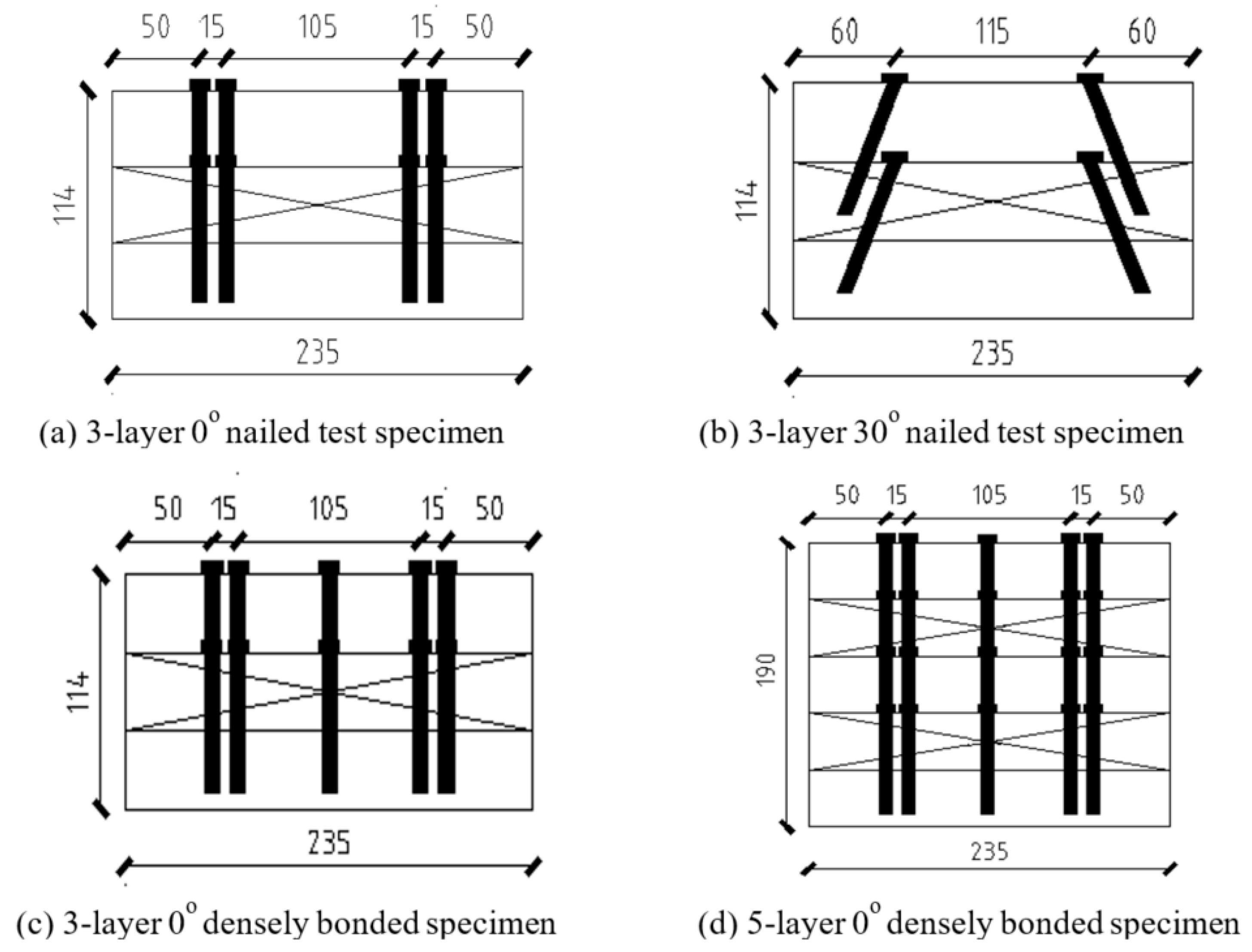
Figure 1. Partial detail view of specimens.
Applsci 10 05983 g001
Figure 2. Partial detail of top view of each group of test specimens.
Applsci 10 05983 g002
Figure 3. Load scheme: (a) Loading; (b) bending moment, and (c) shear force.
Applsci 10 05983 g003
Figure 4. Location of LVDTs in test specimen.
Applsci 10 05983 g004
Figure 5. Strain gauge install on nail-cross-laminated timber (NCLT) panels. (a) Strain gauge mounted on the lower surface; (b) Strain gauge mounted on the side of the 3-layer panel; (c) Strain gauge mounted on the side of the 5-layer panel.
Applsci 10 05983 g005aApplsci 10 05983 g005b
Figure 6. Loading device. (a) Schematic of the loading test; (b) In-situ testing details.
Applsci 10 05983 g006
Figure 7. Load-deflection curves for tested NCLT panels.
Applsci 10 05983 g007
Figure 8. Full view of specimen deformation.
Applsci 10 05983 g008
Figure 9. Effect of nail penetration angle on load-deflection and load-strain relationship. (a) Load-deflection curve; (b) Load-strain curve.
Applsci 10 05983 g009
Figure 10. Effect of nail type on load-deflection and load-strain relationship. (a) Load-deflection curve; (b) Load-strain curve.
Applsci 10 05983 g010
Figure 11. Strain curves of different sections in NCLT panels with different nail connections. (a) Polished rod nail NCLT panels; (b) Screwed NCLT panels; (c) Threaded nail NCLT panels.
Applsci 10 05983 g011
Figure 12. Effect of nail number on load-deflection and load-strain relationship. (a) Load-deflection curves of specimens with a different number of nails; (b) Load-strain curves of mid-span and one-third sections in the specimens with a different number of nails.
Applsci 10 05983 g012
Figure 13. Effect of number of nail layers on load-deflection and load-strain relationship. (a) Load-deflection curve; (b) Load-strain curve.
Applsci 10 05983 g013
Figure 14. Illustration of 3-layers CLT panels.
Applsci 10 05983 g014
Figure 15. Illustration of 5-layers CLT panels.
Applsci 10 05983 g015
Table 1. Details of test specimen.
Test SequenceSpecimen NumberNumber of LayersNail Incidence AngleTypes of NailsNail Specifications\mmTotal Number of NailsSize\mm
1KWL300702354803Threaded nail2.5, 704802350 × 705 × 114
2KWG300702352403Polished rod3.5, 702402350 × 705 × 114
3KWG33080235240330°Polished rod3.5, 802402350 × 705 × 114
4KWS300702352403Screw3.0, 702402350 × 705 × 114
5KWL300702352403Threaded nail2.5, 702402350 × 705 × 114
6KWL500702354805Threaded nail2.5, 704802350 × 705 × 114
KW indicates the bending resistance; L indicates the nail type; G indicates polished rod type; S indicates screw type; the first digit is the number of layers; the second and third digits represent the nail incidence angle; fourth and five digits represent the length of the nail; the last three digits represent the total number of nails.
Table 2. Physical properties of spruce, pine, and fir (SPF).
SpeciesBending Strength/MPaHorizontal Texture Compressive Strength/MPaVertical Texture Compressive Strength/MPaTensile Strength/MPaElastic Modulus/103 MPaDensity (kg/m3)Water Content (%)
Spruce12.537.84.192.3911.243015
Pine10.943.23.683.6610.945515
Fir12.138.93.888.2611.444015
Table 3. Load test results.
Specimen LabelMaximum Mid-Span Displacement/mmBearing Capacity/kN
No. 3 Measuring PointNo. 4 Measuring PointAverage ValueFFmaxF/Fmax
KWL30070235480126.44121.74124.0944.952.00.85
KWG30070235240106.48100.61103.5539.045.80.85
KWG33080235240124.58129.67127.1349.954.40.92
KWS30070235240104.22105.95105.0937.443.30.86
KWL30070235240133.54127.84130.6952.755.20.95
KWL50070235480133.24131.70132.4783.985.70.98
F is the theoretical bearing capacity; Fmax is the maximum bearing capacity from the experiments.
Table 4. Ultimate bearing capacity, deflection, and strain.
Specimen NumberUltimate Bearing Capacity/kNDeflection/mmMaximum Strain Value
KWG3007023524047.96106.424293
KWL3007023524058.46133.725503
KWS3007023524045.46104.223844
Table 5. Ultimate bending moment of all specimens.
SpecimenMoment Theoretical Calculation (Mr)/kN·mMeasured Bending Moment (Ms)/kN·mMs/Mr(MsMr)/Mr (%)
KWL3007023548013.3718.491.3838.29
KWG3007023524013.3716.301.2219.45
KWG3308023524013.3719.361.4544.80
KWS3007023524013.3715.411.1515.26
KWL3007023524013.3719.641.4746.90
KWL5007023548031.9830.490.92−4.66
Table 6. Correction of bending moment.
SpecimenMoment Theoretical Calculation/kN·mMeasured Ultimate Bending Moment/kN·mMeasured Bending Moment/Theoretical Bending Moment(Measured Bending Moment—Theoretical Bending Moment)/Theoretical Bending Moment (%)α
KWL3007023548017.7818.491.063.991.33
KWG3007023524017.7816.300.92−8.321.33
KWG3308023524017.7819.361.088.871.33
KWS3007023524017.7815.410.87−13.331.33
KWL3007023524017.7819.641.1010.461.33