Abstract
The mid-air image is a very powerful method for presenting computer graphics in a real environment, but it cannot be used in bright locations owing to the decrease in brightness during the imaging process. Therefore, to form a mid-air image with a high-brightness light source, a square pyramidal mirror structure was investigated, and the sunlight concentration was simulated. We simulated the tilt angle and combination angle of the condenser as parameters to calculate the luminance of the surface of a transparent liquid crystal display. The light collector was installed at 55 from the horizontal plane and mirror. A high level of illumination was obtained when these were laminated together at an angle of 70. To select a suitable diffuser, we prototyped and measured the brightness of the mid-air image with an LED lamp to simulate sunlight in three settings: summer solstice, autumnal equinox, and winter solstice. The maximum luminance of the mid-air image displayed by collecting actual sunlight was estimated to be 998.6 . This is considerably higher than the maximum smartphone brightness to allow for outdoor viewing, and it can ensure fully compatible visibility.
1. Introduction
Augmented reality (AR) technology is currently used in the entertainment industry to make fictional characters appear as if they exist in real space. One means of achieving AR is by superimposing images on an HMD of a device worn by the user, or on a tablet or other device. However, methods are also available that do not burden users, such as displaying virtual images of computer graphics (CG) characters by using a half-mirror or superimposing CG images on images captured by a camera to display the characters on the screen of a tablet device. The CG characters displayed in the former are virtual images, whereas the characters are displayed only on the screen in the latter; this makes it difficult for observers to interact with the characters in the real world.
Mid-air imaging technology, in which real images are formed in the air by reflecting and refracting the light emitted from a light source, is one of the most useful methods for creating CG and real space. However, it is difficult to observe a mid-air image in bright locations owing to its low luminance. Therefore, it is challenging to use mid-air images outdoors or in bright rooms; thus, the environments in which mid-air images can be used are limited. To address this problem, we propose increasing the luminance of the light source to display a high-luminance mid-air image.
In this study, an optical system for displaying mid-air images with high luminosity is proposed to make such images visible in outdoor environments. As the brightness of a mid-air image is proportional to the brightness of the light source, using a high-luminance display as the light source can produce a high-luminance mid-air image. However, a high-luminance display suffers from the problem of high the power consumption of the backlight, which is not suitable for the design of a high-luminance display considering the sustainable development goals (SGDs). A high-luminance display with low power consumption is realized using concentrated sunlight as backlight for a transparent LCD, and a high-luminance mid-air image is displayed. The design of the light concentrator is optimized using lighting simulation software. Moreover, two experiments are conducted to select a diffuser for the display and to measure the luminance of the mid-air image displayed by collecting sunlight.
2. Related Work
Several methods are available for forming mid-air images; these include those that use a Fresnel lens [1,2], a concave mirror [3], a dihedral corner reflector array (DCRA) [4,5], an ASKA3D plate [6], a roof mirror array (RMA) [7,8], and aerial imaging by retro-reflection (AIRR) [9].
FLOATS V [1] and FuwaVision [2] are available as techniques using Fresnel lenses. These methods can display three-dimensional (3D) images by presenting different images to the left and right eyes. However, the following problem is encountered: the position of the viewpoint is limited in the mid-air image of the Fresnel lens. Therefore, using it in a situation in which multiple people view the image is difficult. Concave mirrors can be combined with lenticular lenses to form 3D mid-air images. However, large concave mirrors are not widely available, and the issue of distortion is also encountered. The DCRA [4,5] reflects the light twice in the transparent material on the grid, whereas the ASKA3D [6] plate reflects the light twice in two orthogonal mirrors and displays the real image at a position that is plane-symmetrical to the light source. The RMAs [7,8] can be used for realizing a mid-air image with a large number of V-shaped roof mirrors arranged in parallel. Although RMAs appear to be easy to manufacture, the required components are not commercially available at present. The AIRR [9] is a method of reflecting and transmitting light from a light source by means of retro-reflective elements and half-mirrors to form a mid-air image at the plane-symmetrical position of the light source with respect to the half-mirror. Although the optical element of this method is available in the market, it exhibits large brightness attenuation.
In this study, we use Aska3D, which is already commercially available and is easy to purchase in large sizes. This is because this device is brighter and more luminous than others. Owing to its structure, of this deviceis referred to as a micro mirror array plates (MMAPs) herein.
Several interaction systems with a mid-air image using MMAPs exist; these include MARIO [10] and Scoopirit [11]. MARIO changes the image formation position in 3D by moving the light source up and down in relation to the mid-air image optical element. The user interacts with the CG character in real space. Scoopirit is a system that allows users to scoop up mid-air images that are displayed upright in or above water with their bare hands. These methods are good examples of how mid-air images displayed by MMAPs can interact with CG in the real world. However, the mid-air images displayed by these methods have low brightness and can only be used in dimly lit rooms. Although the use of MARIO has been demonstrated in public spaces, these demonstrations were limited to the interior of the National Museum of Emerging Science and Innovation. Scoopirit has also been demonstrated, but the actual mid-air image has a maximum brightness of 6.46 . Therefore, it is necessary to increase the brightness of the mid-air images to use such optical designs in bright rooms and outdoors.
Although luminance attenuation is a major challenge for mid-air images, few technologies have been developed to solve this problem. Research has been conducted on increasing the brightness of general displays but not mid-air images [12]. For example, to obtain a high-luminance active-matrix organic LED display that is compatible with high dynamic range technology, the effects of basic components were investigated and a high-luminance display with a peak luminance exceeding 3000 was fabricated. A low power, high-brightness display is realized by creating a highly efficient backlight. Furthermore, many problems, such as heat generation, must be solved for outdoor use. In this study, we propose the use of LCDs, which are available extensively in the market and have reached technological maturity. By using concentrated sunlight as the backlight of a transparent LCD, we can create a display with high luminance, without using electricity for the backlight. We believe that this is beneficial from the perspective of SGDs, as well as energy-consumption reduction.
3. Method
The proposed system is a combination of the Sunny Day Display [13] and the design of a sunlight condenser. In Sunny Day Display, we proposed an optical system for displaying mid-air images with a transparent LCD using sunlight as the backlight. The maximum luminance of the mid-air image displayed by the optical system was 358 . However, this luminance is still insufficient for outdoor visibility. According to a previous study, a luminance of 1000 is suitable under 10,000 environment [14]. Thus, in this study, we set a target value of 1000 to increase the brightness of the mid-air image.
The proposed optical design is presented in Figure 1a. The system consists of a mirror, an infrared reflector, a diffuser, a transparent LCD, a light shield, and MMAPs. First, the incident light is reflected by the mirror and focused on the infrared reflector. The infrared reflector is subsequently used to reflect the infrared rays in the sunlight to reduce the heating of the transparent LCD and to prevent damage thereto by heat. Thereafter, the light moves to the diffuser. The diffused light passes through the transparent LCD, and the color is selected as RGB and black; it then moves to the MMAPs to form a mid-air image. To prevent the entry of undesirable light, we shielded the system from all directions other than the imaging direction of the mid-air image using a light-shielding material.
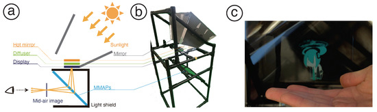
Figure 1.
Overview of the proposed system. (a) Principle: Sunlight is focused by mirrors, reflecting the heat through hot mirrors and diffusing it through diffusers to act as a backlight for the display. MMAPs reflect the light from the display and present a mid-air image in front of the user’s eyes. (b) Implementation: The mirror is fabricated using acrylic cut by a laser cutter. We covered this system with a black cloth to prevent the entry of undesirable light. (c) Example of the displayed mid-air image: It has white (RBG = (255,255,255)) and black (RBG = (0, 0, 0)) parts.
A Fresnel lens was also investigated as a light collection method. Preliminary experiments were conducted, and it was determined that four times the amount of light entering the lens on a clear day was necessary for a high-brightness mid-air image. The focal length of the large Fresnel lens used for the prototype was 60 . We set the distance between the transparent LCD and Fresnel lens to 30 so that the illuminance of the light source was set to four times that at the position of the Fresnel lens.
It was also possible to add a tracking component in the solar panel system for collecting sunlight; however, this method was not adopted in this study. Because using electrical power increases the energy consumption, we did not install a drive system and only used a mirror structure.
4. Simulation
4.1. Conditions
The goal of this study was to design mid-air images with high luminosity. According to the previous research [13], if the illuminance on the surface of the transparent LCD is 40,000 or more, a mid-air image with a brightness of 1000 or more can be formed. Therefore, the criterion for displaying a high-intensity mid-air image is that the illuminance on the surface of the transparent LCD is 40,000 or more.
4.2. Design
Lighting Simulator CAD from BestMedia Co., Ltd. was used as the lighting simulation software. In the simulator, the materials of the Fresnel lens, mirror, light source, and evaluation surface were set. The illuminance on the evaluation surface was compared by changing the position of the light source, the angle of the condenser mirror, and the inclination of the condenser. The plastic lens POLYCA was used as the material for the Fresnel lens and the ratio of the absorptance, transmittance, and reflectance was 0:1:1. For the material of the mirror, the ratio of the absorptance, transmittance, and reflectance was set to 0.15:0:0.85. The radiation type of the light source was parallel light, the number of rays at the time of the simulation was set to 50 million, and the luminous flux was set to 100,000 , which is equivalent to the sun. The size of the evaluation surface was the same as that of the transparent LCD mounted on the device; the width was 100 and the height was 60 . The number of divisions of the evaluation surface was 100, and the average value of the illuminance of each divided cell on the evaluation surface was equal to the illuminance of the evaluation surface.
Figure 2 shows the parameter of this simulation, angle of the mirror attachment, and the change in the angle of the condenser. In the simulation, the tilt of the left, right, top and bottom mirrors was changed from 60 to 80 in 10 increments. The angle between the light condenser and the horizontal plane was changed from 40 to 60 in increments of 5, as shown in Figure 3. For the position of the sun, we set the azimuth in the front of the device at 0 and conducted experiments every 5 with the azimuth and altitude in the ranges of −90 to 90 and 0 to 90, respectively.
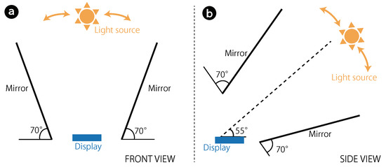
Figure 2.
Angles of the mirror lamination: (a) front view, top and bottom side; (b) side view, left and right side.
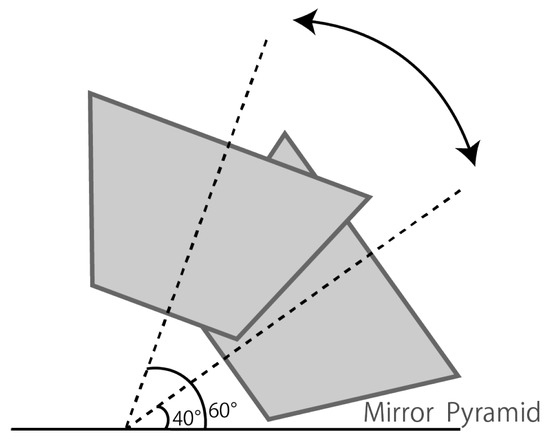
Figure 3.
Angles of the condenser.
Moreover, we calculated the position of the sun every 15 min from 4:00 to 20:00 in Tokyo, Japan. We confirmed how many times per year the conditions matching each simulation condition (angle) occur. Under each condition, the ratio of the time zone when the illuminance was 40,000 or more was calculated.
4.3. Results
The values with and without the Fresnel lens for the illuminance obtained for each condensing design are shown in Figure 4.
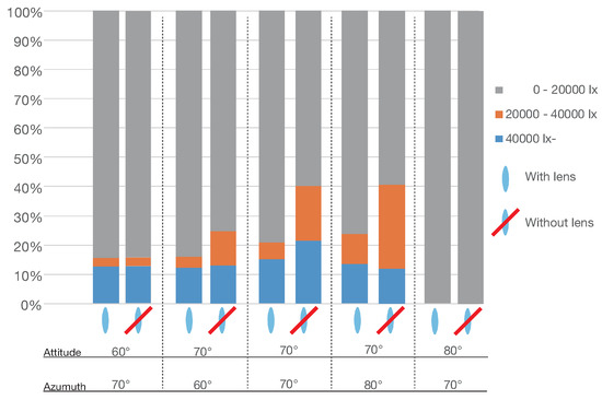
Figure 4.
Proportion of illuminance per light collector design with and without Fresnel lens).
Regardless of the presence or absence of the Fresnel lens, when the mirrors were tilted at 70 and bonded together, the ratio of illuminance above 40,000 was the highest. Moreover, the average illuminance was 40,000 or more when the Fresnel lens was not used compared to when the Fresnel lens was used. Therefore, it is desirable to install the mirrors with an angle of 70 and a condenser device inclined by 55 from the horizontal plane without the use of a Fresnel lens.
Figure 5 presents the relationship between the altitude of the light source and the illuminance on the surface of the transparent LCD when the light condenser was installed at an angle of 55 from the horizontal plane. At this time, the illuminance on the surface of the transparent LCD was 40,000 or more when the azimuth was 0 and the sun altitude was within the range of 30–90. The range of sun altitudes from 30 to 90 included the sun altitude in the winter and summer solstices. That is, by installing the light condenser at an angle of 55 from the horizontal, it is possible to display a high-intensity mid-air image at least at noon for the entire year.
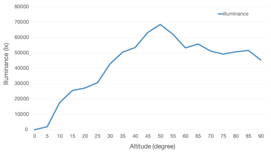
Figure 5.
Illuminance at each solar elevation at 0 azimuth (when the mirror was laminated at 70 and the pyramid was inclined at 55).
5. Implementation
5.1. Prototype
Figure 1b presents the implementation of this system. The transparent LCD was the QUIMAT 3.5-inch LCD (QC35C-JP) from which parts other than the liquid crystal panel were removed, and the mirror was an acrylic mirror. The infrared reflector was an Edmund Optics hot mirror 45 (reflectance: 90%, reflection wavelength: 750 to 1125 , transmittance: 85%, transmission wavelength: 425 to 675 ), and the retro-transmissive optical element ASUKANET ASKA3D-366 (size: 366 × 366 , pitch width: 0.5 ) was used.
5.2. Diffuser Selection
The brightness of the mid-air image displayed using multiple diffusers was compared and the diffuser to be used was selected. The brightness of the mid-air image displayed was measured by simulating the movement of the sun using a super-narrow-angle LED light (with an irradiation angle of 3). The azimuth was 0 directly in front of the device, and the position and tilt of the super-narrow-angle LED light were moved by 10 in the range of −50 to 50. The movements of the sun at the summer solstice, autumn equinox, and winter solstice were simulated. The brightness of each mid-air image was measured by replacing 10 types of diffuser plates for each position of the super-narrow-angle LED light. The diffuser used were circular diffuser known as LSD0.5, 1, 2, 3, 10, 20, 30, 40, 60, 80 (the numerical values indicate diffusion angles), by Luminit, LLC. An image in which a white circle was drawn on a black background was displayed as the mid-air image, and the brightness of the center of the white circle was measured from three directions: the front of the mid-air image, and oblique directions of 10 and 20 from the front.
5.3. Results
Figure 6, Figure 7 and Figure 8 present the luminance measurement results of the summer solstice, autumn equinox, and winter solstice, respectively. According the experimental results, the magnitude of the mid-air image brightness was dependent on the direction of the light source and type of diffuser for each season, and the magnitude of the illuminance on the surface of the transparent LCD for each season could be determined.
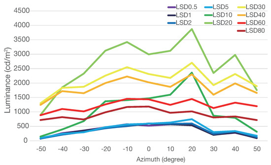
Figure 6.
Measurement results when moving LED light as sun of summer solstice.
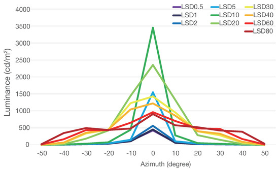
Figure 7.
Measurement results when moving LED light as sun of autumn equinox day.
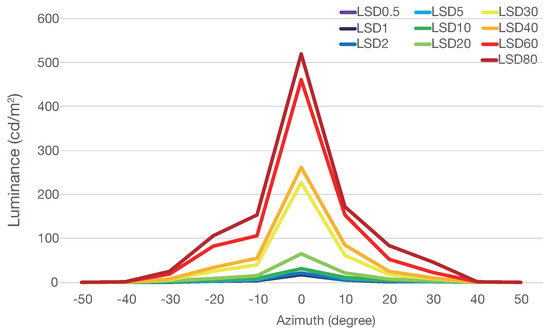
Figure 8.
Measurement results when moving LED light as sun of winter solstice.
From Figure 6, it is clear that in the summer solstice, LSD20 was highest in the light source azimuth range of , but the brightness decreased significantly in the light source azimuths of 50 and −50. The use of LSD30, which was very bright in the light source azimuth range of , is considered to be effective.
It can be observed from Figure 7 that LSD5, LSD10, LSD20, LSD30, and LSD40 were over 1000 in autumn. When the light source direction was 0, the brightness of the mid-air image when using LSD10 was the highest. However, when LSD10 was used, the brightness decreased when the light source direction was 10 or more. Furthermore, when LSD20 was used, the brightness decreased when the light source direction was 20 or more. Similar changes in the luminance were observed for LSD30 and LSD40, and the values decreased gradually as the light source direction changed from 20 or more to 50. Therefore, among the candidate diffusers that exceeded 1000 in the maximum luminance, it was deemed preferable to use LSD30, which had higher brightness in wider light source directions.
According to Figure 8, in the winter solstice, the brightness of each diffuser used was the same regardless of the light source, and the brightness was the highest when LSD80 was used. Therefore, it was considered preferable to use LSD80 in the winter solstice.
The measurement results from the directions of 10 and 20 are illustrated in Figure 9 and Figure 10. It can be observed that when the position of the light source was displaced from the front of the device, the direction in which the mid-air image could be viewed the brightest was considered to be offset from the front of the mid-air image. This is because the light source has directivity, and MMAPs re-image the light emitted from the light source at a plane-symmetrical position. Therefore, when observing from a plane-symmetrical position with MMAPs as a boundary with respect to the incident direction of parallel light, a mid-air image is obtained, and it appears bright.
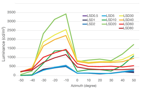
Figure 9.
Measurement results from 10 when moving LED light as sun of summer solstice.
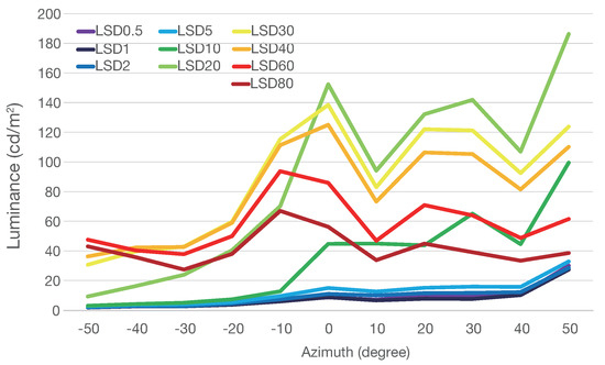
Figure 10.
Measurement results from 20 when moving LED light as sun of summer solstice.
It is considered that this is the reason that locations existed at which the brightness of the mid-air image did not exceed 1000 when the illuminance at the measurement time was greater than 40,000 .
5.4. Luminance Measurement in the Open Air Using Sunlight
The device was installed facing south, and the brightness of the mid-air image was measured directly in front of the mid-air image and at an angle of 10 from the front. The image that was displayed as a mid-air image was an image in which a white circle was drawn on the same black back surface, and the luminance of the center of the white circle was measured as an indoor experiment. We also used three diffuser types, namely LSD20, LSD30, and LSD80, and measured the brightness of the mid-air image for each diffuser type every 15 min from 10:45 a.m. to 17:00 p.m.
The measurement date was 1 February 2020. There were no clouds around the sun, and the sunlight was not blocked.
The maximum luminance on the measurement day was 998.6 when LSD80 was used at 12:00 as shown in Figure 11. At 14:15, the transparent LCD was not exposed to sunlight and the brightness thereafter was less than 100 .
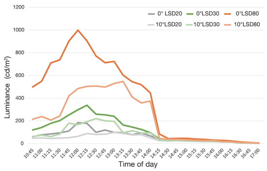
Figure 11.
Results of luminance measurements at 0 and 10 from the front of the mid-air image in the open air using sunlight.
Similar to the experiment in the room, when measured from an angle of 10 directly in front of the mid-air image, the brightness value was the highest when the orientation of the light source was 0 or greater.
Figure 1c is the mid-air image provided by our system in the open air using sunlight, and Figure 12 shows the color of the mid-air image of our system. The settings of the camera are the same, but the color of the light sources are different. (a) is normal white, and (b) is an orange filter similar to the sunset color. The image color of (b) becomes more reddish than (a). Although the color temperature of the light source has an effect, a multi-color image can be shown.
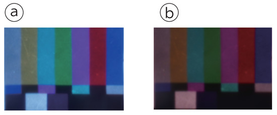
Figure 12.
Color of mid-air image. Settings of the camera are the same. (a) The light source is white-LED video light (YONGNUO YN600 II, 5500 K color temperature). (b) The light source is the same as that in (a) with a 3200 K filter.
6. Discussion
The limitation of the display, removal of the light on the surface of the MMAPs surfaces, and the limited time width for displaying a high-intensity mid-air image are considered to be the problems encountered by this system.
First, the display has certain limitations. The light transmittance of a transparent LCD is low (approximately 8%). Additionally, the display color is affected by the color of the light source; thus, as the color temperature of the light source changes, the color temperature of the mid-air image also changes. The replacement of the diffuser, which must be performed during winter, is another problem. This is only performed twice a year, before and after winter.
Second, the MMAPs also have some limitations. As explained in the Methods section, the system needs to be enclosed by a light shield to prevent the entry of undesirable light. Additionally, it was found that in outdoor environments, the ambient light was reflected onto the surface of the MMAPs surfaces and that mid-air image was inferior. In this regard, it is considered that the reflection of ambient light can be removed by the same principle as the optical isolator by removing the polarizing plate of the liquid crystal and using a circular polarizing plate before the MMAPs.
Finally, we consider the limited time width in which a high-intensity mid-air image is displayed. We believe that by using an auxiliary light source according to the illuminance, it is possible to provide sufficient generation thereof. In future work, we would like to design suitable auxiliary light.
7. Conclusions
We aimed to display a bright mid-air image by concentrating sunlight using a mirror. For evaluation, we selected the diffuser and adjusted the brightness of the mid-air image by moving the LED light as if it were sunlight. When selecting the diffuser to be used along with the LED light, it was found that the diffuser type that provides the highest mid-air image brightness changes depending on the position of the light source. In Japan, the 30 diffuser is optimal for spring, summer, and autumn. On the other hand, in winter, an 80 diffuser is the most suitable.
The maximum brightness of the mid-air image displayed by sunlight was 998.6 on the measurement day in February in Tokyo, Japan.
The mid-air image was displayed with higher brightness than that in the previous research, and the brightness was sufficiently higher than that of a smartphone, which can be considered to be contributing to the use of mid-air images outdoors.
Author Contributions
Conceptualization, N.K.; Data curation, K.Y.; Formal analysis, K.Y.; Funding acquisition, N.K.; Investigation, N.K.; Software, K.Y.; Writing—original draft, N.K.; Writing—review & editing, N.K. All authors have read and agreed to the published version of the manuscript.
Funding
This work was supported by PRESTO, JST (JPMJPR16D5), and JSPS KAKENHI Grant Number JP20H04223.
Conflicts of Interest
The authors declare no conflict of interest.
References
- Kakeya, H. P-65: FLOATS V: Real-Image-Based Autostereoscopic Display with TFT-LC Filter. SID Symp. Dig. Tech. Pap. 2004, 35, 490–493. [Google Scholar] [CrossRef]
- Nii, H.; Kening, Z.; Yoshikawa, H.; Htat, N.; Aigner, R.; Nakatsu, R. Fuwa-Vision: An auto-stereoscopic floating-image display. In Proceedings of the SIGGRAPH Asia 2012 Emerging Technologies, Singapore, 28 November–1 December 2012; pp. 13:1–13:4. [Google Scholar] [CrossRef]
- Huang, T.; Zhang, X.; Liao, H. Floating autostereoscopic display with in situ interaction. J. Soc. Inf. Disp. 2019, 27, 785–794. [Google Scholar] [CrossRef]
- Maekawa, S.; Nitta, K.; Matoba, O. Transmissive optical imaging device with micromirror array. In Three-Dimensional TV, Video, and Display V; International Society for Optics and Photonics (SPIE): Bellingham, WA USA, 2006; Volume 6392, pp. 130–137. [Google Scholar]
- Yoshimizu, Y.; Iwase, E. Radially arranged dihedral corner reflector array for wide viewing angle of floating image without virtual image. Opt. Express 2019, 27, 918–927. [Google Scholar] [CrossRef] [PubMed]
- Otsubo, M. Optical Imaging Apparatus and Optical Imaging Method Using the Same. U.S. Patent 8,702.252 B2, 22 April 2014. [Google Scholar]
- Maeda, Y.; Miyazaki, D.; Maekawa, S. Aerial Imaging Display Based on a Heterogeneous Imaging System Consisting of Roof Mirror Arrays. In Proceedings of the IEEE 3rd Global Conference on Consumer Electronics (GCCE’14), Tokyo, Japan, 7–10 October 2014; pp. 211–215. [Google Scholar] [CrossRef]
- Maeda, Y.; Miyazaki, D.; Maekawa, S. Volumetric aerial three-dimensional display based on heterogeneous imaging and image plane scanning. Appl. Opt. 2015, 54, 4109–4115. [Google Scholar] [CrossRef]
- Yamamoto, H.; Tomiyama, Y.; Suyama, S. Floating aerial LED signage based on aerial imaging by retro-reflection (AIRR). Opt. Express 2014, 22, 26919–26924. [Google Scholar] [CrossRef] [PubMed]
- Kim, H.; Takahashi, I.; Yamamoto, H.; Maekawa, S.; Naemura, T. MARIO: Mid-air Augmented Reality Interaction with Objects. Entertain. Comput. 2014, 5, 233–241. [Google Scholar] [CrossRef]
- Matsuura, Y.; Koizumi, N. Scoopirit: A Method of Scooping Mid-Air Images on Water Surface. In Proceedings of the 2018 ACM International Conference on Interactive Surfaces and Spaces (ISS ’18), Tokyo, Japan, 25–28 November 2018; Association for Computing Machinery: New York, NY, USA, 2018; pp. 227–235. [Google Scholar] [CrossRef]
- Eguchi, S.; Nakamura, D.; Kusunoki, K.; Kawashima, S.; Takita, Y.; Seo, S.; Dobashi, M.; Misawa, C.; Nakada, M.; Yamazaki, S. 35-1: Strategy for Developing an Ultra-High-Luminance AMOLED Display. SID Symp. Dig. Tech. Pap. 2018, 49, 433–436. [Google Scholar] [CrossRef]
- Koizumi, N. Sunny Day Display: Mid-Air Image Formed by Solar Light. In Proceedings of the 2017 ACM International Conference on Interactive Surfaces and Spaces (ISS’ 17), Brighton, UK, 17–20 October 2017; Association for Computing Machinery: New York, NY, USA, 2017; pp. 126–131. [Google Scholar] [CrossRef]
- Kim, M.; Jeon, D.H.; Kim, J.S.; Yu, B.C.; Park, Y.; Lee, S.W. Optimum display luminance depends on white luminance under various ambient illuminance conditions. Opt. Eng. 2018, 57, 1–9. [Google Scholar] [CrossRef]
© 2020 by the authors. Licensee MDPI, Basel, Switzerland. This article is an open access article distributed under the terms and conditions of the Creative Commons Attribution (CC BY) license (http://creativecommons.org/licenses/by/4.0/).