1. Introduction
The computer mouse is one of the most widely used devices for interacting with a computer. It is primarily used as an input device for interacting with visuals displayed on a computer screen—diagrams, pictures, graphs, etc. The computer mouse is a handheld (haptic) device, but the output or feedback made by it is, in most cases, visual or aural. A user only perceives the passive feedback of holding the mouse in their hands instead of acquiring rich and diverse feedback that would be provided when interacting with real objects. This uneven fidelity on different modalities in the interaction may result in the decrements of the efficiency and intuitiveness of interaction [
1]. To remedy this, this paper focuses on a computer mouse providing a holistic haptic feedback for providing a rich virtual experience to the interactor. This is in particular beneficial to the visually impaired who rely heavily on their sense of touch.
During haptic interaction, humans use both tactile and kinesthetic information [
2,
3]. The tactile sense deals with texture, pressure, and lateral forces on the skin, while the kinesthetic sense handles the perception of stiffness, motion, and normal and rotational forces. In order for a haptic display to exhibit a holistic perception of a virtual object, it needs to provide both kinds of haptic information in physically correct form [
4,
5]. Combining this rich feedback with the most common interface, i.e., computer mouse, would maximize the positive effect of this holistic haptic experience.
Various haptic devices have been designed to provide different kinds of haptic feedback. Most of these devices offer only a single kind of haptic feedback, i.e., any one of tactile feedback, force feedback, and thermal feedback. Tactile feedback is generally provided using pin arrays, voice coil actuators, or linear resonant actuators, etc. [
6,
7]. Force feedback is delivered using pneumatic actuators, or motors, etc. [
8,
9,
10]. Thermal feedback is usually implemented using peltier, piezoelectric, or microfluidic elements (haptx), etc. [
11,
12]. The advantage of using a single mode of feedback is that the form factor of the device can be compact, as it houses a single type of actuator. The downside is the lack of other modes of feedback to create a holistic haptic experience.
On the other hand, certain devices do offer multi-mode haptic feedback [
13,
14]. These deploy a combination of the above mentioned elements for generating various modes of feedback concurrently. The multi-mode devices can provide a richer haptic experience by incorporating more than one kind of haptic feedback. However, the provision of each type of feedback adds an additional module or end-effector which adds to the form factor and complexity of the device. A higher number of modalities may result in a bigger device with multiple end-effectors, which may interfere with the normal haptic experience.
Another shortcoming that can be related to both types of devices is the variability in their structure. In terms of devices used for interacting with computers, most come in unique forms and shapes. It requires a user to get accustomed to the device itself before it can provide a satisfactory haptic experience. Furthermore, a majority of them tend to target a certain location of the hand, i.e., mostly the finger tips.
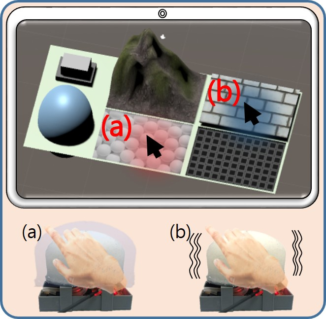
The current paper aims at a haptic system capable of providing multi-mode feedback with single actuator to the user’s whole hand. To this end, we propose a pneumatically-controlled, silicone-based haptic mouse capable of providing multi-mode haptic feedback using a single end-effector, as shown in
Figure 1. The dome of the mouse is made from flexible and lightweight silicone which allows efficient pneumatic control. It consists of two distinct layers, i.e., a stretchable layer and a non-stretchable layer. The mouse is capable of rendering three different haptic modalities using a single end-effector, i.e., providing static pressure to generate geometry, high frequency vibrations to generate texture or other tactile sensations, and impact feedback to generate impulses or clicking events. The non-stretchable layer is used to hold the form of the mouse, while the stretchable layer is used for generating high frequency vibrations and impact responses by rapid inflation and deflation. The silicone end effector rests on top of a typical mouse circuit board to ensure the normal operations of a mouse. A computer mouse capable of offering the above mentioned modalities can be used to perceive texture, geometry, and contours of virtual objects in addition to the clicking feedback. Details and analysis of these characteristics are provided in the following sections.
The rest of the paper is organized as follows.
Section 2 highlights the pertinent literature in the field of pneumatics and previous approaches used for creating a haptic mouse. In
Section 3 the design, structure, and control modules of the haptic mouse are elaborated.
Section 4 discusses the various haptic effects that the haptic mouse can generate and the characteristics of the proposed system. Haptic rendering based on the various modalities of the haptic mouse are elaborated in
Section 5. The evaluation of the rendering capabilities of the system is discussed in
Section 6. Lastly, a brief summary of the system, limitations, and possible future directions are provided in
Section 7.
2. Related Works
The haptic mouse proposed in this paper is powered with the help of a pneumatic system. Previously, pneumatics have mostly found applications in force feedback systems while rarely focusing on providing vibrotactile or static pressure. In the following subsections some of the previous studies using pneumatics will be put forward. Since our prototype is a computer mouse, we also highlight some of the previous attempts made at producing a haptic mouse.
2.1. Pneumatic Actuation for Haptic Feedback
Pneumatic actuators use the rapid flow of compressed air to inflate/deflate or push/pull mechanical parts to create diverse haptic feedback. In the literature, pneumatics have vastly been used to provide force feedback by manipulating pistons or some other mechanical parts [
15,
16,
17]. Other systems have used pneumatics in combination with tactile or force feedback actuators to generate multimodal haptic effects [
18,
19,
20]. In another study, a pneumatic system was used to create powerful haptic feedback using a comparatively smaller end-effector [
21]. Noritsugu et al. used this higher force weight/size ratio of pneumatic systems to design smaller sized wearable actuators to enhance usability and user experience [
22].
Another advantage is the ease of control of a pneumatic system. A variety of feedback can be achieved by controlling the volume, velocity, etc., of air, thereby ensuing multiple kinds of effective haptic feedback [
23]. Most existing actuators cannot simultaneously create different kinds of haptic feedback and mostly the size of actuator dictates the strength of the output; i.e., the larger the size, higher the feedback strength [
14].
One of the commonalities of pneumatic systems is that they are used for either delivering large force feedback or as wearables. This means that these are standalone systems which are not readily used by users in their day to day lives. The proposed haptic mouse makes use of the pneumatic system as an add-on to a standard mouse. In this way, the haptic mouse can be used as a replacement for a standard mouse. In addition to that, the haptic mouse provides a variety of haptic feedback for a rich user experience.
2.2. Haptic-Enabled Computer Mouses
Several studies have attempted to design a haptic device in the shape of a computer mouse to deliver tactile or kinesthetic feedback. Some of those focused solely on tactile or kinesthetic feedback, and a few of them provided a combination. In [
24] the authors provided tactile feedback at the fingertips using a standard mouse with a piezoelectric actuator incorporated. M. Price et al. used a mechanically steered wheel mouse to provide force feedback while exploring mazes on a touch screen [
25]. In [
26], R.G. Golledge et al. provided tactile and kinesthetic feedback to render virtual walls and textures. Similarly, the haptic mouse used in [
27] rendered tactile and kinesthetic feedback to select targets on a computer screen. Other studies used mouse-like devices to render shapes [
28] or shapes and textures [
29]. In [
1] the authors provided all the sub-modalities of tactile feedback using a mouse-like structure.
The above mentioned devices either provide a single form of actuation or use multiple end-effectors to provide multiple haptic effects. The present paper, however, focuses on generating both tactile and kinesthetic feedback in the form of three distinct haptic effects using the same end-effector. These haptic effects are static pressure to render geometry, vibrations to generate texture, and impact to generate crisp button clicks.
3. Haptic Mouse Fabrication and Hardware Control
The main focus of this study was that the haptic mouse should be able to completely replace a typical mouse, and it should be able to render complex and powerful haptic feedback (vibration, static pressure, and impact) rather than simply expressing an interaction feedback. Another deliberation was that it should be able to effectively deliver haptic feedback to fingers and palm of the user. It was considered that operating the haptic mouse should be convenient for users over long periods of time. Typical haptic devices have the disadvantage of being too complex or unfamiliar for use with a conventional computer environment. Therefore, it was decided to produce the haptic mouse in a shape similar to the typical mouse to maintain usability.
3.1. Fabrication
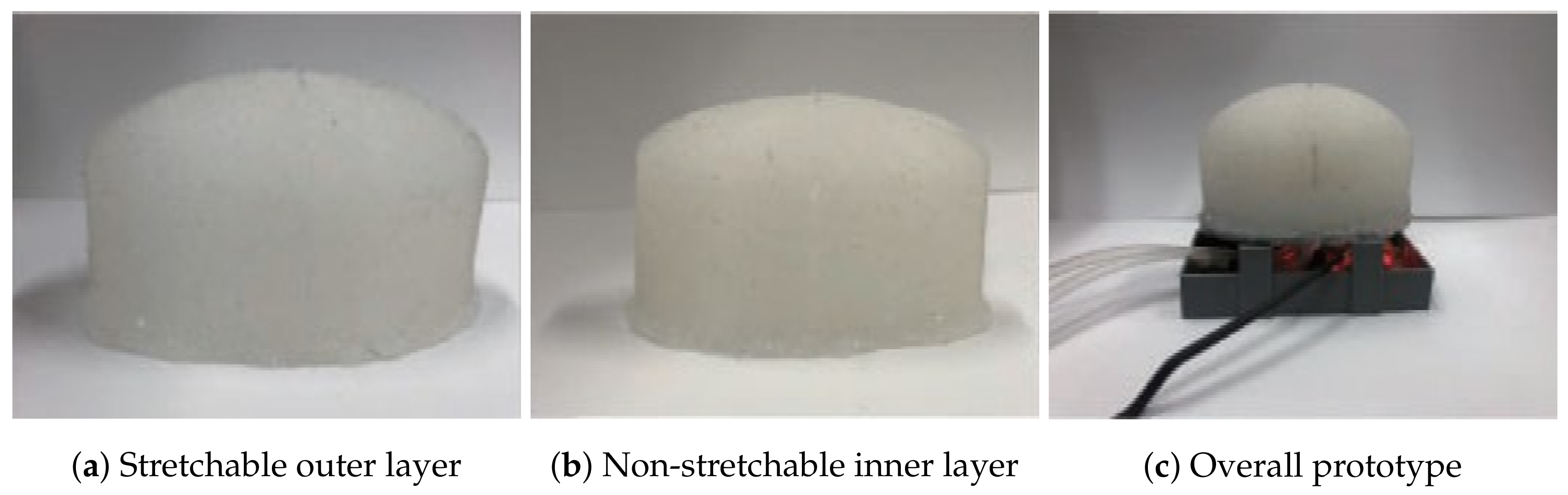
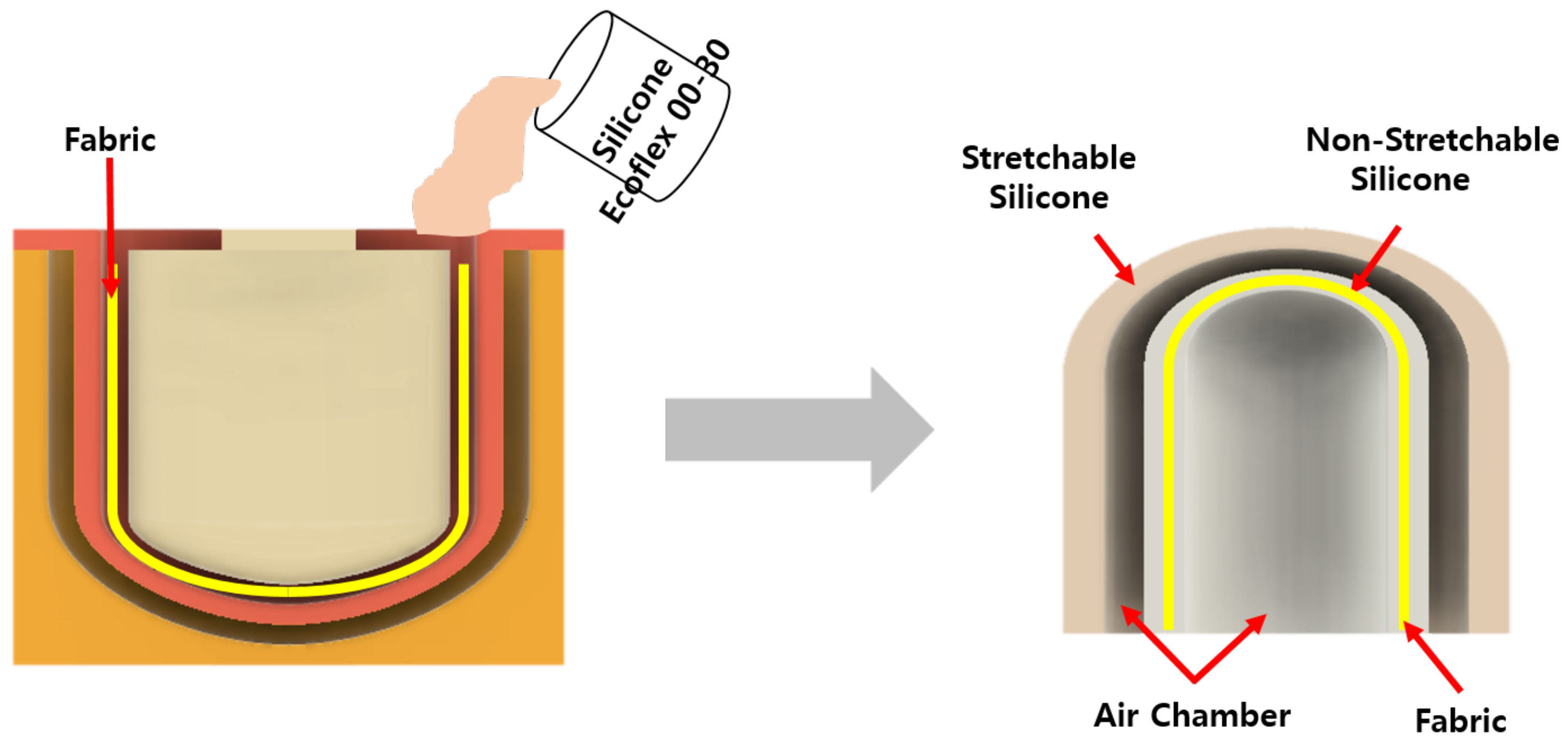
The haptic mouse is a combination of a standard mouse control circuit and a silicone housing in the shape of a standard computer mouse. The silicone housing, in the form of a dome, provides the various haptic effects. These effects are enabled by the dome being divided into two distinct layers, i.e., the stretchable layer and the non-stretchable layer. Two air cavities are also present in the structure. One air cavity is inside the non-stretchable layer and the other air cavity is between the two layers of silicone. The overall fabrication process is shown in
Figure 2. The fabrication process of the dome is presented in the following sections in detail.
3.1.1. Materials
The main material used for the fabrication of the dome was Ecoflex 00-30 (Young’s modulus = 0.1694 MPa, Shore hardness = 00-30, 100% modulus at 10 Psi) platinum-based cure silicone (Smooth-on, Inc., Pennsylvania, United States).
Other silicone models can also be used, but according to our past experience and from our previous studies, we determined that Ecoflex 00-30 is soft, safe to touch, has a high value of tear strength even with a thin layer, and provides a larger and more rapid displacement compared to the other models [
30].
3.1.2. Stretchable and Non-Stretchable Layers
As mentioned earlier, the basic design of our haptic mouse comprised of two distinct silicone layers. The stretchable layer can be produced by the traditional technique of mixing, molding, and curing the Ecoflex silicone. This layer swells in size when air is pumped into it. In order to construct a non-stretchable layer, a fiber-based fabric (or other stretch resistant material) is added to the silicone during the molding process. The addition of the alien material into the silicone stops it from stretching when air is blown into it. Therefore, instead of an increase in size of the silicone, an increase in stiffness occurs.
The stretchable layer is used to render various haptic modalities, i.e., static pressure, vibrations, and impulse response. The non-stretchable layer carries a two-fold functionality. First, it is used to hold the shape of the soft haptic mouse. Second, it enhances the effect of the stretchable layer. Since the non-stretchable does not inflate due to air pressure, when air is blown into the cavity, only the stretchable layer inflates. If both sides of the cavity were lined with stretchable layers, the inflation towards inside of the mouse would have been futile and resulted in a lesser degree of inflation towards outside.
3.1.3. Curation of Stretchable and Non-Stretchable Layers
The first step in the fabrication process is the creation of 3D printed molds for curing the silicone layers. The mold for the stretchable layer is larger than the mold for non-stretchable layer. The second step is to cast the silicone layers into the desired shape. The two silicone compounds (silicone rubber compound A and B) must be mixed in equal ratios. The mixture must then go through the degassing process; i.e., the mixture is kept inside a vacuum chamber to remove any air bubbles that might be trapped inside. Afterwards, the mixture is to be poured into the 3D printed casts made for the stretchable and non-stretchable layers. In case of the non-stretchable layer, a portion of the mixture is to be poured into the 3D printed cast. A fiber-based fabric (cut to exact dimensions) should then be placed on top of the mixture, and the remaining mixture must be poured into the cast to trap the tissue inside the mixture. Both the casts containing the mixtures are then to be set aside to rest for four to six hours at room temperature.
The last step is to combine both the layers together and attach that to the base of a standard mouse. A 3D printed housing must be built for the circuitry of a standard mouse. The non-stretchable layer must be glued to a flat 3D printed surface (bottom plate). An opening must be made in the bottom plate and a hose must be inserted into the air cavity inside the non-stretchable layer. The stretchable layer must be placed on top of the non-stretchable layer and glued to the bottom plate. Another opening must be made in the bottom plate for inserting an air hose into the stretchable layer. Finally, the bottom plate must be attached to the mouse housing with the help of 3D printed pillars.
3.2. Hardware
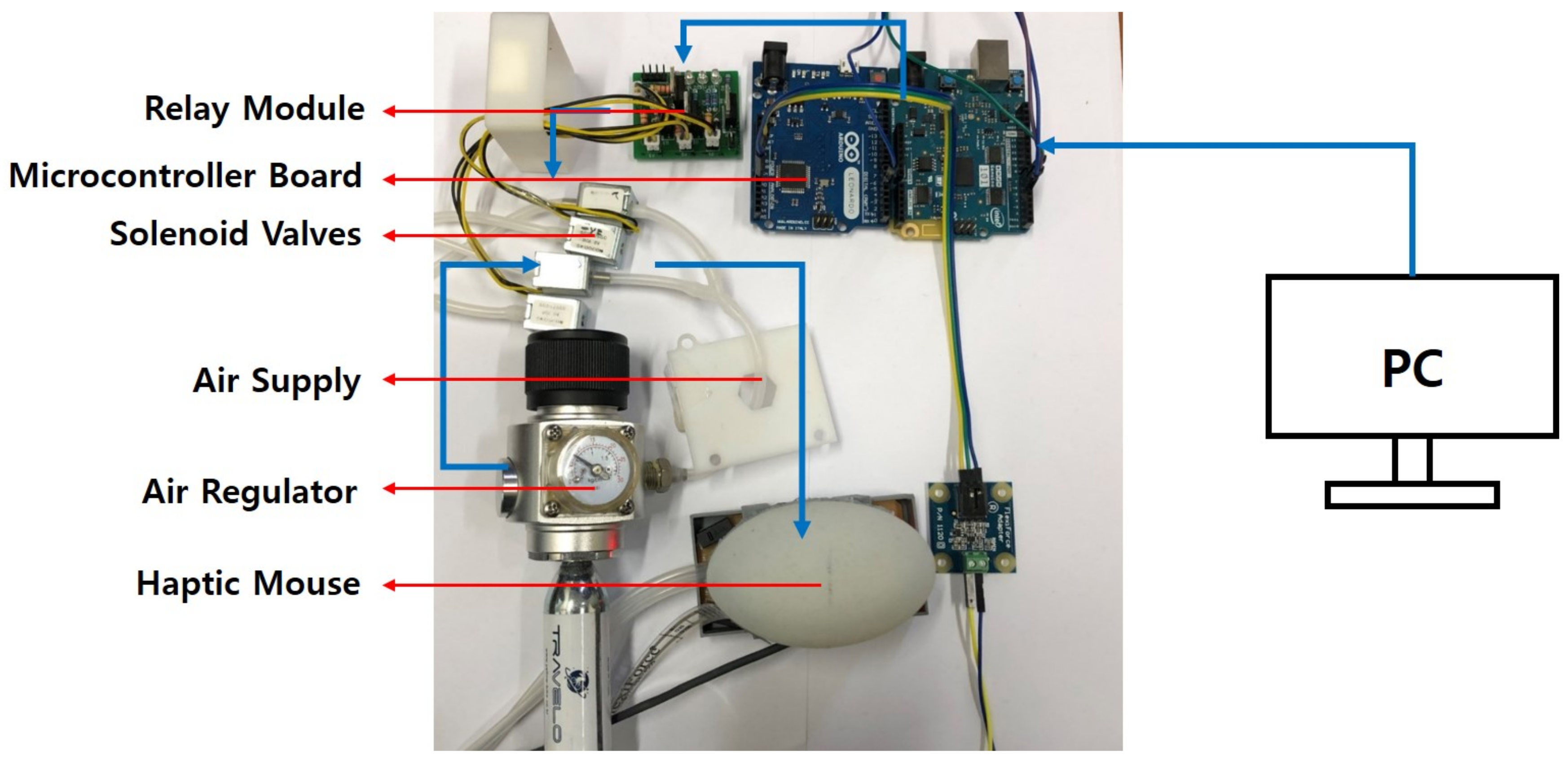
The haptic mouse is mainly driven by pneumatic control which inflates or deflates the stretchable and non-stretchable layers. Depending upon the volume and frequency of inflation/deflation, various haptic effects are generated. Pneumatic control is achieved by using solenoid valves which respond to change in input voltage. The pneumatic valves are operated using control circuitry which enables the different haptic effects. Other hardware, apart from the pneumatic control, consists of components for mouse event handling. The hardware used in this system is shown in
Figure 3, and further detailed in the following subsections.
The central part of pneumatic control is the group of valves that control the flow of air in and out of the silicone layers. Each layer requires two solenoid valves for operation, i.e., a positive valve (SC0526GC, Skoocom Technology Co.,Ltd, Shenzhen, China) and a negative valve (SC0526GF; Skoocom Technology Co., Ltd, Shenzhen, China). The positive valve is used to pump air into the mouse layers, while the negative valve is used to extract air from the mouse layers. There are a total of two layers in the mouse and each layer requires two valves; thus, a total of four solenoid valves are used. The valves are connected at one end to the layers and at the other end to a source of compressed CO2. The regulator for the air supply is operated at 5 and 10 psi for the haptic effects, which is further detailed in the following sections.
3.2.1. Pneumatic Control Hardware
The valves are electrically connected to the analog output port of Arduino Genuino 101. Both the valves remain closed as long as they receive a digital low (zero volts), and they remain open as long as they receive a digital high (2 volts). A transistor relay circuit is used to protect the valves from overdrive. The Arduino communicates with a computer through serial communication. Data are sent from a computer to the Arduino, which then uses the positive and negative valves accordingly.
3.2.2. Mouse Event-Handling Hardware
The solenoid valves are also connected to Arduino Leonardo. Arduino Leonardo has in-built mouse event handling protocols; therefore, events such as mouse clicks and drags are controlled through it. A force sensor (Flexiforce A201 (0-25lb), Tekscan) is used to mimic the click button in the haptic mouse. When the user clicks on the force sensor, the Arduino first sends a mouse pressure event to the PC. Second, the Arduino opens the positive valve of the stretchable layer for a predefined amount of time (300 ms) to provide feedback for the click event. When the click button (force sensor) is released, the Arduino again generates a mouse event and opens the negative valve to release the pumped air.
4. Multimodal Haptic Effects
As mentioned earlier, the haptic mouse presented here is able to render three different kinds of haptics effects, i.e., static pressure, high frequency vibrations, and impact. The rendering methodologies and working principles of these different effects are detailed in the following subsections.
4.1. Static Pressure
Static pressure can be defined as a certain amount of pressure or force exerted over a sustained period of time. In the current system, static pressure is achieved by opening the positive valve for a given duration of time and then closing it (while also keeping the negative valve closed). The volume of the air chamber grows as long as air is blown into it (while remaining below the mechanical tear point). When the valves are closed, the air remains trapped inside the chambers and thus produces the sensation of static pressure on the hand holding the haptic mouse. Once the static pressure is no longer required, the negative valve is opened and the trapped air is allowed to escape, bringing the haptic mouse to it’s initial state.
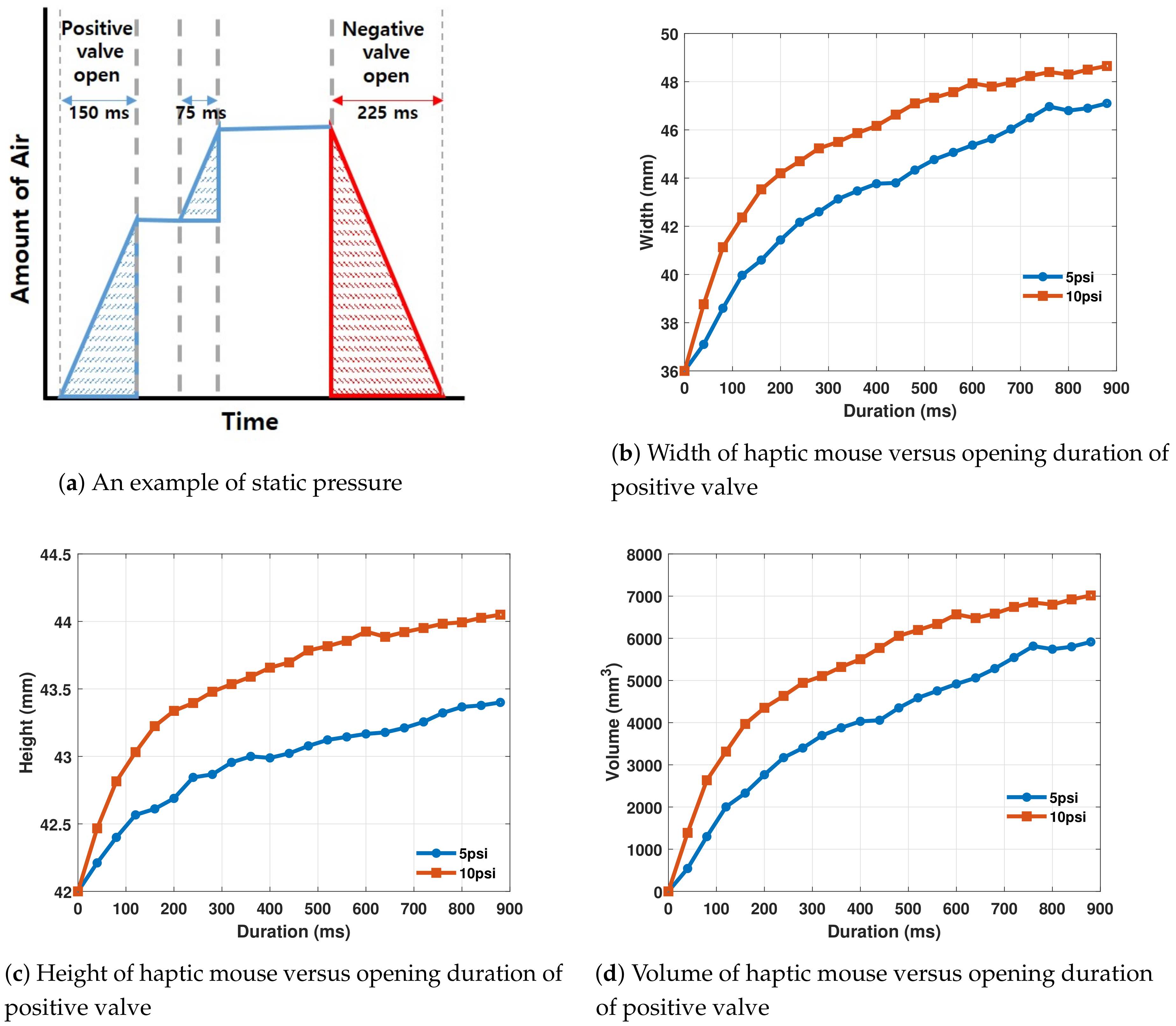
The main variable in producing static pressure is the duration of time for which the positive valve is opened. The amount of static pressure can be adjusted by operating the valves. It can be increased by reopening the positive valve, or decreased by opening the negative valve for a certain amount of time. An example is given in
Figure 4a, showing static pressure for having an initial opening duration of 150 ms and a subsequent one of 75 ms.
Experiment: Relation Between Volume and Duration
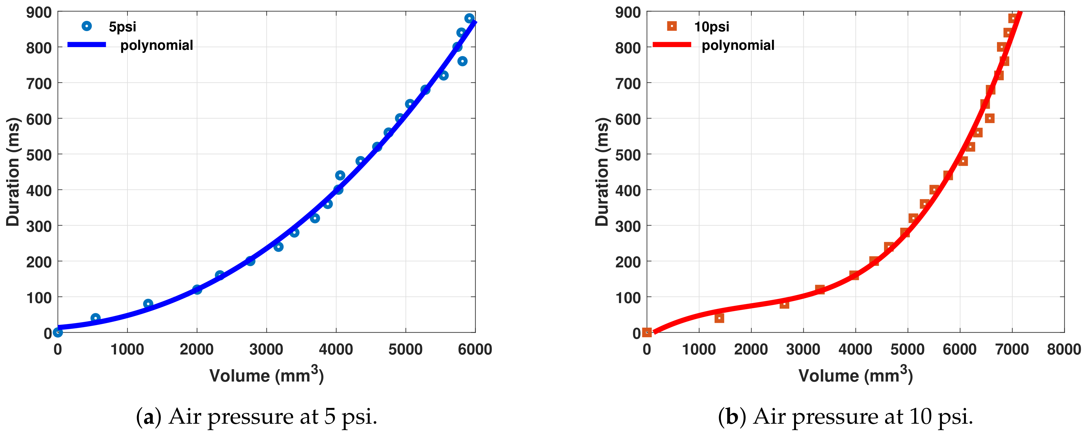
The key factor in rendering and perceiving static pressure is the amount of increase in the volume of the haptic mouse. In order to render a given volume successfully, the relationship between volume and duration of opening the valves should be calculated. For this purpose, an experiment was carried out to map the duration of opening of valves against changes in volume at different air pressure levels.
Setup and Procedure: In this experiment, the maximum duration for opening the positive valve was fixed at 880 ms, in order to avoid damage to the air chamber. The positive valve was opened in increments of 40 ms at a time, so as to achieve a continuous relationship between duration and volume over the course of 880 ms (22 increments). The volume calculation includes the length, width, and height; however, in our current case, the length dimension of haptic mouse was constrained. Thus, change in volume occurred only through changes in width and height. The default width of the haptic mouse was 36 mm and height was 42 mm, while length was 24 mm and kept constant.
The whole experiment was carried out at two different air pressure levels, i.e., 5 and 10 Psi. Each experiment was repeated three times and the results were averaged.
Results: Width and height changes were individually calculated for the increasing duration. As mentioned earlier, length of the mouse was kept constant by clamping it and stopping it from expanding. The shape of the haptic mouse can be considered as one half of an ellipsoid. The formula for calculating the area of an ellipsoid is,
where
,
, and
are the length, width, and height of the ellipsoid. The
was used because the haptic mouse was half an ellipsoid. The changes in width, height, and volume with respect to duration are given in
Figure 4.
As is evident, an increase in duration resulted in an increase in the total volume of the haptic mouse. Initially, increase in duration of air flow caused a rapid increase in volume; however, after some time the increase in volume slowed down, and towards the end, i.e., above 800 ms, an increase in duration caused only a negligible increase in volume. The air had higher pressure at 10 psi as compared to 5 psi, and thus the total volume increase at 10 psi was higher than the volume increase at 5 psi.
4.2. High Frequency Vibrations
High frequency vibrations can be generated by rapidly opening and closing the positive and negative valves alternatively. In order to render synchronous vibrations, the positive and negative valves should be opened for the same amount of time during each cycle. Thus, each valve can be opened for a maximum of half a cycle, and as a result we achieve a duty cycle (the amount of time for which a valve is open) of 50% for each valve. This ensures that all the air that is pumped into the air chamber during the positive valve opening is extracted during the negative valve cycle. The two main characteristics of a vibration signal are its amplitude and frequency. The amplitude (displacement of the stretchable layer) of the vibrations is governed by the amount of time the positive valve remains open during each cycle.
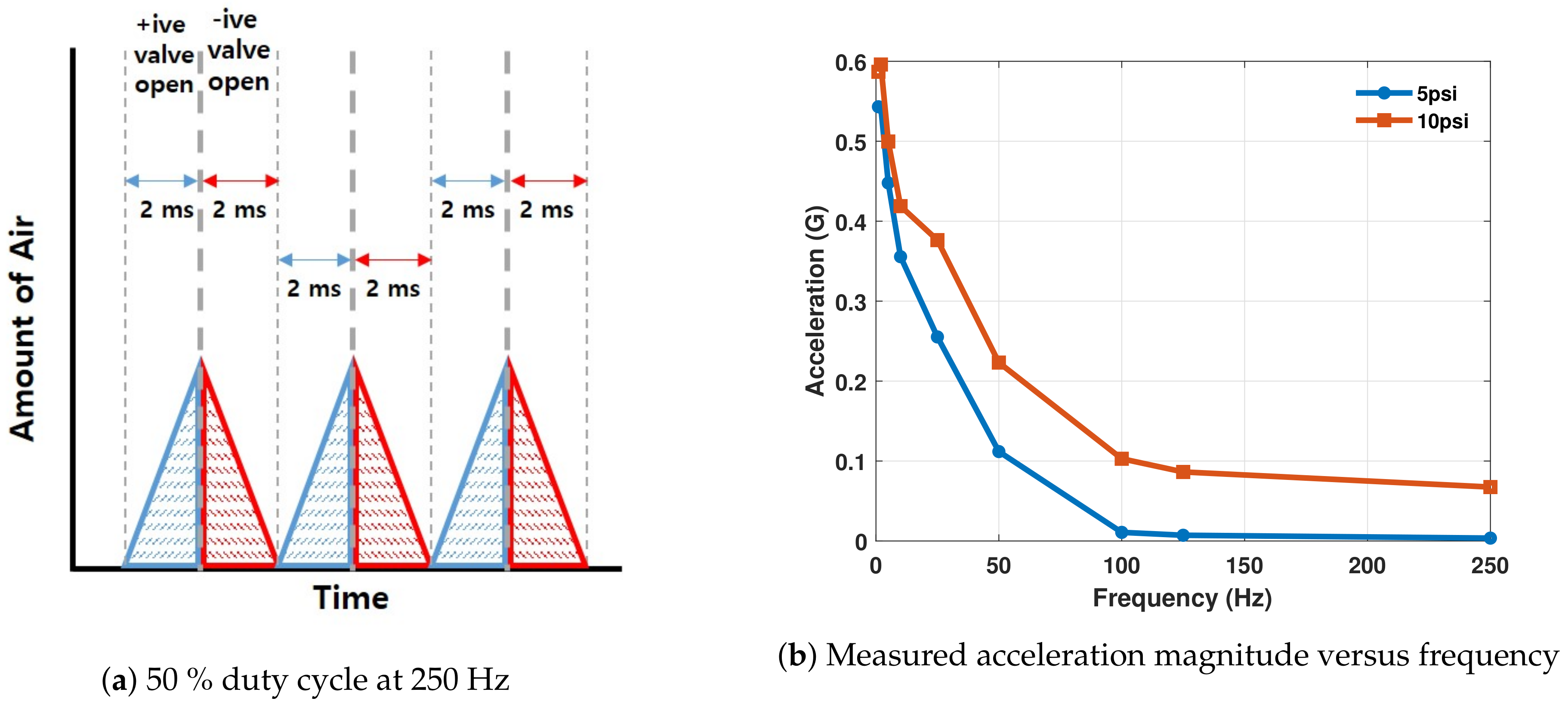
The frequency of vibrations is calculated by the speed at which the solenoid valves can open and close. The solenoid valves used in the haptic mouse have a response time of 2 ms. In one cycle we operate both the valves for 2 ms; therefore, the total minimum duration required by the valves is 4 ms. The highest frequency that can be achieved with a 4 ms response time is 250 Hz (as f = ). Thus, the highest frequency which can rendered with the haptic mouse is 250 Hz.
The rendering frequency and duty cycle (while less than 50%) can be changed according to the needs of application. The frequency and duty cycle are sent to the Arduino from a computer and the Arduino calculates the corresponding duration for opening each valve. This is achieved through the following formula.
where
f is the desired frequency and
represents the desired duty cycle. An example of 250 Hz frequency at 50% duty cycle is provided in
Figure 5a.
Experiment: Relation Between Frequency and Acceleration
After establishing the maximum possible frequency and duty cycles for the haptic mouse, it is important to calculate the amount of acceleration/displacement that is produced by the haptic mouse at various frequencies and to establish whether the displacements at different frequencies are perceivable.
Setup and Procedure: In this experiment, a total of nine (1, 2, 5, 10, 25, 50, 100, 125, 250 Hz) different frequencies were rendered at 50% duty cycle. An accelerometer (ADXL335; Analog Devices, Inc) was attached on one side of the haptic mouse which recorded the acceleration. A total of five seconds of data was collected for each frequency at a sampling frequency of 1000 Hz. The acceleration values were collected from the axis perpendicular to surface where accelerometer was attached. The whole experiment was conducted for two different air pressure levels, i.e., 5 and 10 psi.
Results:
Figure 5b shows the relationship between frequency and acceleration in gravitational force (g-force or Gs) units. It can be seen that the haptic mouse produces greater acceleration/displacement at lower frequencies. As the frequency increases, the magnitude of acceleration also decreases. This can be accredited to the fact that at lower frequencies the valves remain open for longer duration. A longer opening duration results in a higher change in volume of the haptic mouse and thus creates a higher acceleration value. Furthermore, the haptic mouse produces higher acceleration at 10 psi as compared to 5 psi across all the frequencies due to higher air pressure (more air entering the mouse in the same amount of time).
The acceleration magnitude achieved for 10 psi air pressure ranged from 0.1 G to 0.6 Gs. According to [
31,
32], this range of acceleration magnitude is sufficient and effective for human perception. Therefore, it was decided to use the 10 psi air pressure for vibration feedback.
4.3. Impact Response
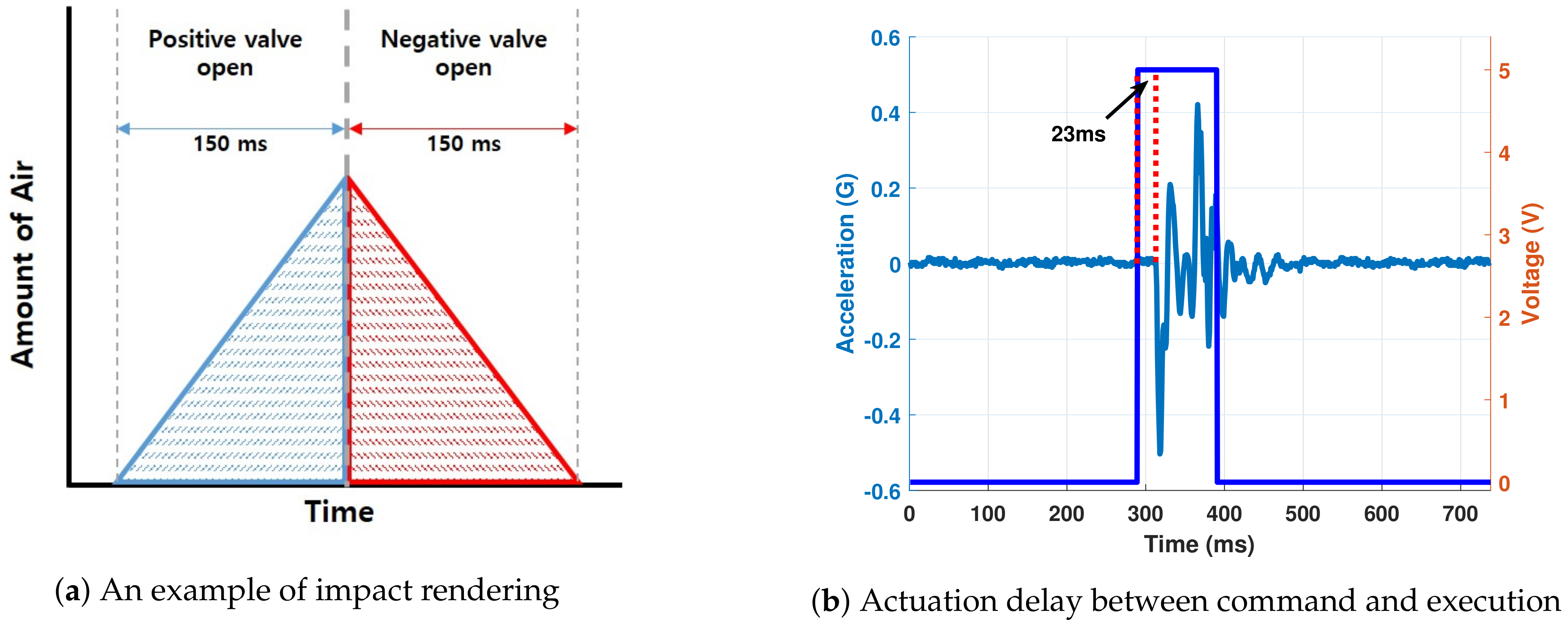
The main idea behind impact is to deliver a high amount of force in a relatively short interval of time. This imparts the illusion of a strike rather than sustained pressure, as was the case in static pressure rendering. Impact rendering can be achieved by opening the positive valve for a short amount of time and allowing the air to fill up the haptic mouse. Afterwards, the positive valve is closed and negative valve is opened to drain all the air immediately. A user or receiver would perceive a sudden spike of high pressure for a limited amount of time. The solenoid valves used in the haptic mouse have a response time of 2 ms, which makes it possible to deliver a sudden impact force. It was empirically established that opening the positive valve for 100 ms at 10 psi air pressure renders rigid, brisk, and precise impact feedback. However, the type of impact feedback can be changed depending on the application or rendering requirement. An example of 150 ms impact rendering is shown in
Figure 6a.
Experiment: Actuation Delay in Impact Rendering
The main idea behind impact rendering is to deliver a large enough force in a rapid fashion at a precise point in time. The first key point in this statement is that the magnitude of force should be large enough to deliver an impact. The second point is the ability to generate a force swiftly, or in other words, a high gradient of acceleration. It has already been established that the haptic mouse can generate acceleration magnitude of up to 0.6 Gs, as shown in
Figure 5b. An experiment was conducted to test the practical swiftness of the impact capabilities of the haptic mouse. The main aim of this experiment was to test if any delay between the time an impact command is instructed and the time it is actually executed by the hardware occurs.
Setup and Procedure: The delay in question here is the time it took for actual execution of impact from the time a command was generated at the Arduino output pin (electrical high). This was done by attaching an accelerometer to the haptic mouse and recording its readings with a time stamp of occurrence. The Arduino board was programmed to fire commands at exact points in time and this time was also recorded. When the Arduino outputs an electrical high at the corresponding output port, the valves begin to fill up the mouse chambers with air. This causes an increase in volume of the mouse, which triggers accelerometer readings. The accelerometer records these readings along with a timestamp.
Results: An inspection of both sets of data showed a slight discrepancy between the output command time and the actual actuation time. The time it took to send the output command was 264 ms, while the accelerometer recorded its first significant change at 287 ms. The difference in times shows that there was a delay of 23 ms between command and actual execution. This 23 ms is the actuation delay of the haptic mouse. The impact response and timings are shown in
Figure 6b.
The delay in a pneumatic system can depend on a number of factors, the primary candidate being the response time of the valves, which in this case is 2 ms. Apart from the valves, delays can occur due to the source of air supply and its efficiency. The length of the hose also plays an important role. According to previous research ion haptics and multimodal feedback, a delay between 27 ms and 71 ms can be deemed as perceptually insignificant [
33,
34,
35].
6. Evaluation Experiment
The characteristics and capabilities of the haptic mouse were discussed in detail in the aforementioned sections. The haptic mouse is capable of generating multimodal feedback using the same end-effector/actuator. The types of feedback include generating static pressure, high frequency vibrations, and impact. In order to test the feasibility and realism of the feedback types, a psychophysical experiment was designed. In this experiment, virtual objects were rendered and the participants were asked to compare them against their real counterparts. The main aim of this experiment was to judge the effectiveness of the haptic mouse to render various kinds of haptic feedback.
6.1. Participants
A total of eight participants participated in the experiment. Their average age was 25 (range 22–29). Three out of eight participants had prior experience of haptic feedback, while the remaining participants had never experienced haptic feedback. In addition, all eight participants reported familiarity with the use of a computer mouse.
6.2. Stimuli
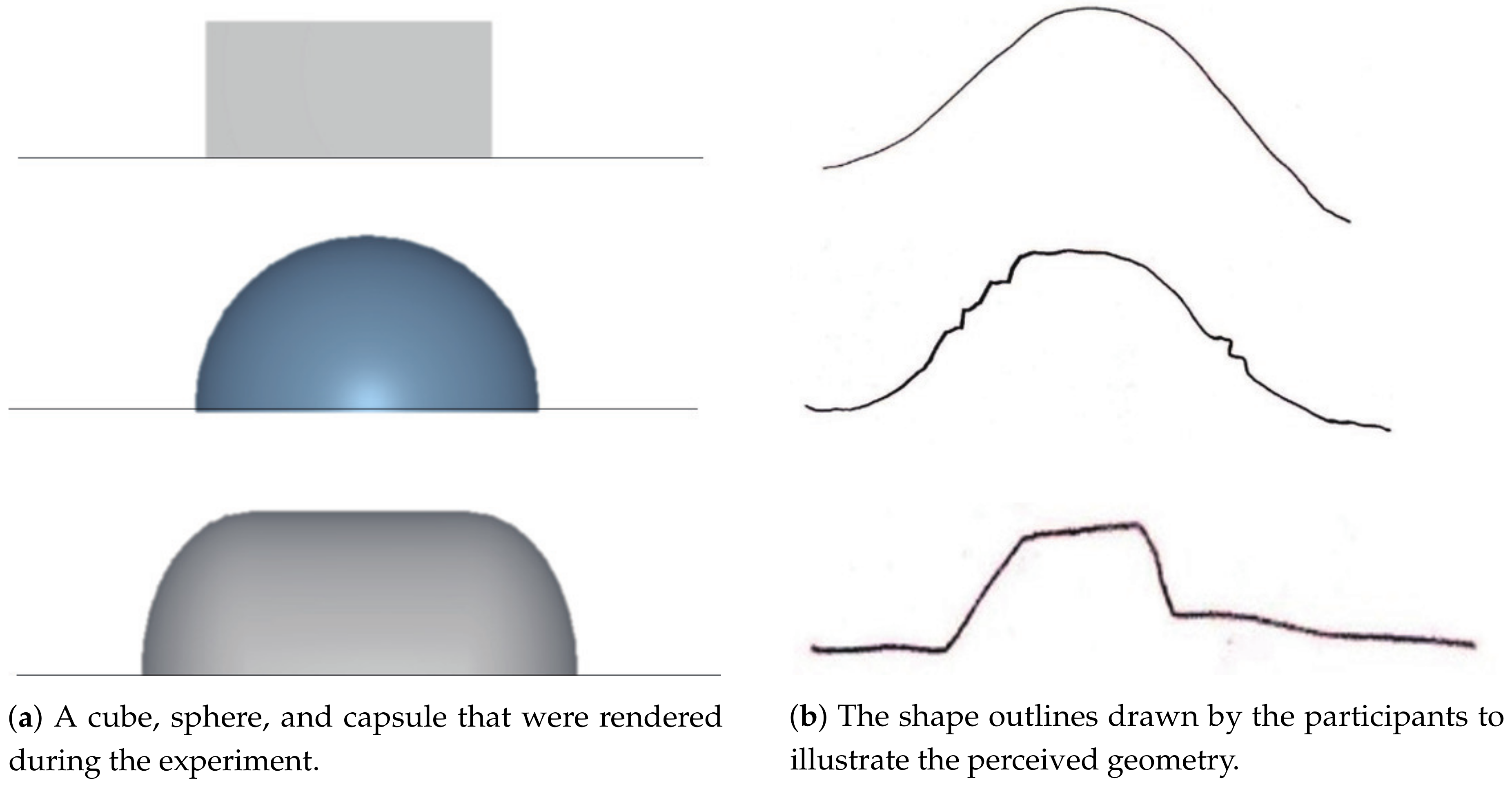
The experiment was divided into three sub-types based on the rendered objects. First, the haptic mouse was used to render geometry of virtual objects using static pressure. The objects in this sub-experiment were a cube, a sphere, and a capsule. These shapes were chosen because they represent subtle diversity. The cube has uniform surfaces with sharp edges, the circle does not have any sharp edges and instead follows a continuous decline, and the capsule lies somewhere in between these two. The capsule has areas of uniform height and contains gentle edges as compared to the sharp edges of a cube. The shapes are shown in
Figure 8a.
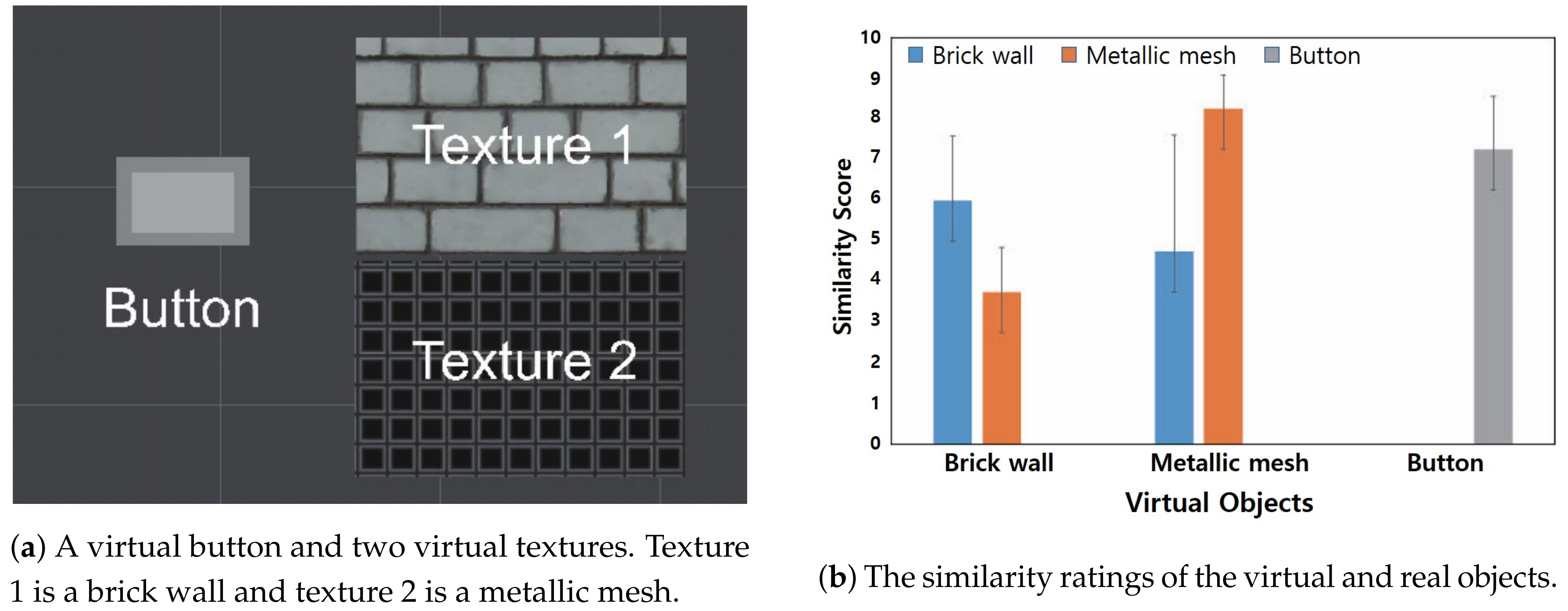
Second, two different textures were rendered using the high frequency vibrations of the haptic mouse. These textures were a brick wall and a metallic mesh. These were compared to their real counterparts, i.e., an actual brick wall and a real metallic mesh. Third, a virtual button was rendered on the screen using the impact response of the haptic mouse and it was being compared against a real life button. The second and third sub-types were merged into a single procedure during the experiment. The textures and button are shown in
Figure 9a.
6.3. Procedure
Every participant took part in all the sub-experiments. The first experiment was to test the ability of the haptic mouse to portray geometry information using its static pressure response. The three stimuli, i.e., cube, sphere, and capsule, were presented in random order. The participants were presented with one stimulus at a time and were asked to draw its shape. They used the haptic mouse to move along the surface of each object. They were not allowed to see the shape on the screen; instead they had to rely solely on the haptic response.
In the second experiment (combined sub-type two and three), the subjects were given three objects: a metallic mesh, a brick wall, and a button. Similarly to the first experiment, the participants were not informed about the object being rendered. They used the haptic mouse to interact with the surface of the presented virtual object, one at a time. The participants were asked to rate the similarity/realism of the rendered virtual object against all the real textures and button. A higher value of similarity/realism meant that the textures were more alike, and a value of zero meant that they were completely different.
6.4. Results
The results from the geometry rendering experiment are provided in
Figure 8b, and those from the texture and button rendering are shown in
Figure 9b. It can be seen from
Figure 8b that the participants were more successful at identifying and reproducing the shapes of the sphere and capsule than they were with the cube. The contours of a cube were perceived as similar to those of a sphere. This can be accredited to the fact that the edges of a cube exhibit a sharp decline, whereas the haptic mouse was unable to render such a sharp decline in slope. In order to render vertical edges, the air to the haptic mouse had to be pumped/drained instantaneously. However, in its current state, it was unable to accomplish such feedback.
The participants were able to differentiate the various textures and button presented in experiment two. The virtual-real pairs of textures and button received high similarity values from the participants, as shown in
Figure 9b. The most obvious was the button, as it did not receive any similarity to the textures from all the participants. The button did not receive a complete ten which shows that the haptic feedback was not exactly the same as a real button; however, an average value of around seven meant a high amount of similarity to a real button.
In case of the textures, the real–virtual pairs received a high similarity score; i.e., the virtual brick-wall received a high similarity score to the real one, and the virtual metallic mesh was rated as highly similar to the real metallic mesh. Some of the participants rated the virtual brick-wall as somewhat similar to the real metallic mesh and vice versa. However, the overall results show that the participants were able to perceive the differences in rendering and correctly identify the virtual textures and button.
7. Discussion
In this study, a pneumatically-actuated soft mouse was proposed to deliver myriad haptic information. A mouse-shaped end-effector was created with a silicone-based end effector that could change in size, produce vibrations, and render impact feedback. The haptic mouse can be used to help users recognize objects efficiently and from a new perspective using different types of haptic feedback. Among other things, the focus was on expressing the geometry of objects, and in addition, properties (texture, etc.). To express the properties of objects, we identified the characteristics of various effects that the end-effector can express. We quantified the change in the volume of the haptic mouse by injecting air into the air chamber and the vibration effect by rapidly injecting and extracting air. The results measured for each feedback showed satisfactory values and a wide range to be applicable to various objects. These digitized data can be used in real-world applications to render haptic feedback of geometries and texture of objects.
The haptic mouse can easily be built into various forms (being made of silicone) and configured for use. This means that a very specific end-effector focusing only on a particular type of feedback and application can be constructed to produce a higher effect. It can be argued that the pneumatic actuator with a soft end-effector can be successfully reconfigured to find application in a number of other studies.
The haptic mouse proposed in this study is not intended to deliver highly realistic haptic feedback; instead, it is used to add haptic information to visual information so that users can more effectively perceive objects in the process of recognizing objects. In the current study, the participants were not allowed visual information during the experiment. The experiments were designed in this way to test pure haptic capabilities of the haptic mouse. In a real world application scenario, haptic feedback created in synchrony with visual information would provide a highly immersive and in-depth perception of virtual objects.
An avenue where the haptic mouse can find a useful application is in helping people with disabilities. Visually impaired people can use the haptic mouse to get a feel for the textures of virtual objects. The shape and end-effector of the haptic mouse is such that it covers the whole hand. Hence, the visually impaired users can form a holistic impression of the geometry of virtual objects.
Limitations and Future Work
The current study proposed a haptic mouse capable of rendering multimodal haptic effects. However, there are certain limitations which can impede its widespread application. The haptic mouse consists of two silicone layers with an air chamber in between them. This air chamber is responsible for vibrating the whole top layer of the mouse, which means that air chamber extends under the entirety of the top layer. The huge size of this air chamber can prove to be a hindrance in applications wherein sharp feedback is required. An example of this phenomenon occurred during the cube geometry rendering in
Section 6, wherein the haptic mouse could not render sharp edges. A potential solution could be to divide the air cavity into multiple smaller chambers. All the smaller chambers would be individually controlled. Such a design would provide a faster response, and aid in rendering more complex geometries.
The current system uses compressed CO cartridges for air supply. These cartridges run out after a few minutes of continuous use and have to be replaced. There are other mechanisms which use atmospheric air for supply; however, those systems are slower and not effective for high frequency haptic feedback. One solution would be to store the extracted air in another cartridge and reuse it afterwards. This, nonetheless, requires pertinent expertise and a significant hardware overhead. Currently, there does not exist a feasible solution to solve this problem; however, with improving technology and hardware, feasible alternatives could be available in the future.


