1. Introduction
The energy crises in the 1970s led to the birth and development of large-scale wind turbines, which were further commercialized in the 1980s. Nowadays, environment-friendly wind power is at a rapidly developing stage, with land-based wind power accounting for a large proportion [
1,
2,
3]. Onshore wind power had started earlier, with a large installed capacity at present. In comparison, the installed capacity of offshore wind power generation keeps growing, owing to its advantages such as favorable wind conditions and high applicability. Among the offshore wind power support structures, the single-pile foundation is most widely applied. Other multipile foundations, gravity foundations, and suction bucket foundations also account for a certain proportion [
4,
5].
Wind turbines, towers, and foundations belong to high-rise structures, which need to withstand complex external environmental loads during their operation, and face problems such as structure vibration [
6,
7,
8,
9,
10], soil–structure coupled vibration [
11], seismic dynamic response [
12,
13], and vibration reduction control [
14,
15,
16]. Offshore wind turbines, especially, have to face many challenges in complex ocean environments, including waves, currents, and erosion. The interaction between the support structure and soil and the dynamic response analysis method involves the safe operation of the structure. Up to now, scholars around the world have conducted a number of in-depth studies on single- and multipile foundations, which are frequently applied to offshore wind power generation [
17,
18].
Along with the large-scale construction of onshore wind farms, the form of onshore wind power infrastructure is constantly being improved and optimized, thereby forming the base structures that are adapted to different geological conditions. The wind power generation system belongs to a towering structure; however, due to the particularity of its structural form, it is slightly different from the ordinary tower structure in terms of mass distribution. For example, the wind turbine on the top has a large mass, so the bottom foundation structure is subjected to the coupling of torque–vertical load–horizontal load–bending moment load (i.e.,
T–
V–
H–
M) under the external random wind conditions [
19,
20,
21,
22]. Therefore, the stability of a wind power foundation structure is the key to ensuring the normal operation of wind power generation. Since the upper load has to be transferred to the base, the connection between the bottom of the tower and the top of the base is a key component, which is usually embedded on the top of the base. The commonly used structures of connection include the foundation ring and the anchor bolt. Note that the former is mostly used because of its simple structure, massive production, easy quality control, and convenient installation and construction [
23,
24,
25].
The main loads that a wind turbine foundation bears include vertical, horizontal, and bending moment loads transferred from the upper tower tube, wind turbine, and fan blade. At present, the corresponding design and research mostly focus on the stress state of the structure under the coupling effect of these loads. In order to obtain the maximum wind energy in practice, the angle needs to be adjusted quickly and smoothly to align with the wind direction. At this time, the foundation structure will bear the horizontal torque load, which is transmitted by the wind turbine yaw [
26,
27,
28]. Since the horizontal torque load caused by fan yaw is relatively small compared with the bending moment load, it is often not considered separately in the conventional foundation design. However, it is still not clear how the torque load is transmitted within the wind turbine foundation and which part mainly bears the torque load. The top radial reinforcement on the top of the foundation, during the design process, is mainly based on the uplift resistance of the foundation, while its contribution to torsion resistance or the stress state and the level of top radial reinforcement under the torque load is not taken into account. This is mainly due to the fact that, at present, there is no definite conclusion about the torque load-sharing ratio of antipull bars. However, since the torque load is an indispensable component under the composite loading system, how to determine the sharing ratios of the top radial reinforcement and the foundation ring is still a difficult problem.
In order to study the transmission path of the torque load in the foundation, the force characteristics of the foundation under the horizontal torque load alone are studied in this paper without considering the simultaneous coupling effects of vertical, horizontal, and bending moment loads. First, the sources and the transfer process of the torque load are analyzed. Then, an experimental torque-loading system of an indoor scale model is proposed, and torsional tests on four foundation ring extended models are carried out. On this basis, the stress and force transfer mechanism of the top radial reinforcement, the antipull bar, the foundation ring, and the surrounding concrete under the torque load are analyzed in detail. Finally, the transfer characteristics of the torque load in the foundation ring expanded foundation, as well as the torque load-sharing ratios, are determined.
2. Torque Transmission Mechanism and Experimental Scheme
2.1. Torque Load Source and Transmission Process
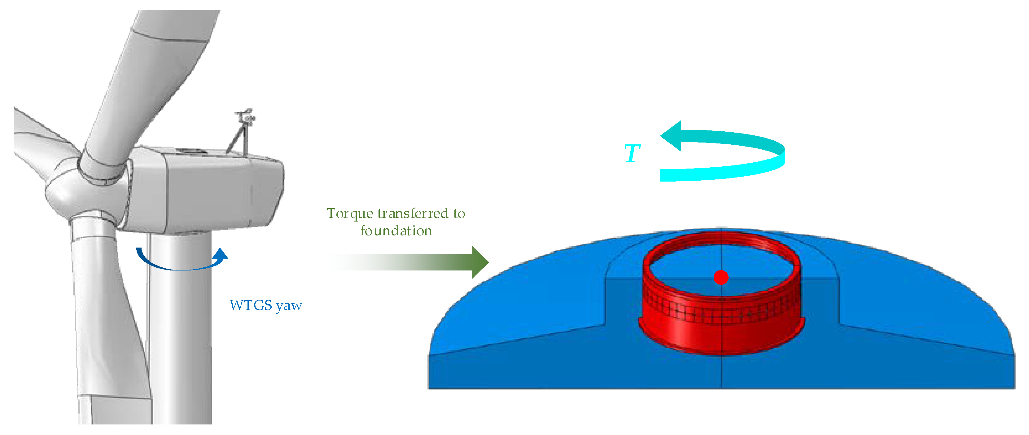
When the turbine is in operation, the wind load on its blades and the load caused by the wind turbine yaw will act on the top of the tower through the structure and the transmission mechanism and will be further transferred to the top of the foundation structure [
29,
30,
31,
32]. The torque load on the horizontal plane, which the foundation structure bears, is mainly caused by fan yaw load, as shown in
Figure 1. Due to the gyroscopic effect, the yaw operation will cause the gyroscopic force to act on the top of the tower when the fan is yawing, i.e., the yaw load. At different stages of yaw movement, the load is divided into the starting load and uniform rotating load.
(1) Start deflection
When a fan is yawing, the yaw activation torque on the tower is
where
A is the swept area of the wind blades;
PH is the average pressure on the swept area of the wind blades;
ew is the eccentricity between the aerodynamic force and the center of the wind blades.
At the beginning, in addition to torque, there is also a lateral force acting on the top of the tower, i.e.,
where
mM is the total mass of the generator and blades;
s the distance from the centroid of total mass to the tower;
is the yaw acceleration.
(2) Uniform deflection movement
If reasonable acceleration time data are not available for a wind turbine with a passive yaw system, then the acceleration duration is assumed to be 1 s, and the system’s yaw rate is adopted. For a wind turbine equipped with an active yaw system, its angular velocity is usually small and can be ignored accordingly. In this case, the following loads will be applied:
where
Z is the number of blades;
IB is the moment of inertia of blades relative to the rotor shaft;
is the yaw rate.
In this paper, the scale model test was based on a 70-m tower foundation structure with a 1.5 MW wind turbine in a real project. Based on the above calculation method, the horizontal torque load was obtained, and the torsion test on the scale model was carried out using a graded method.
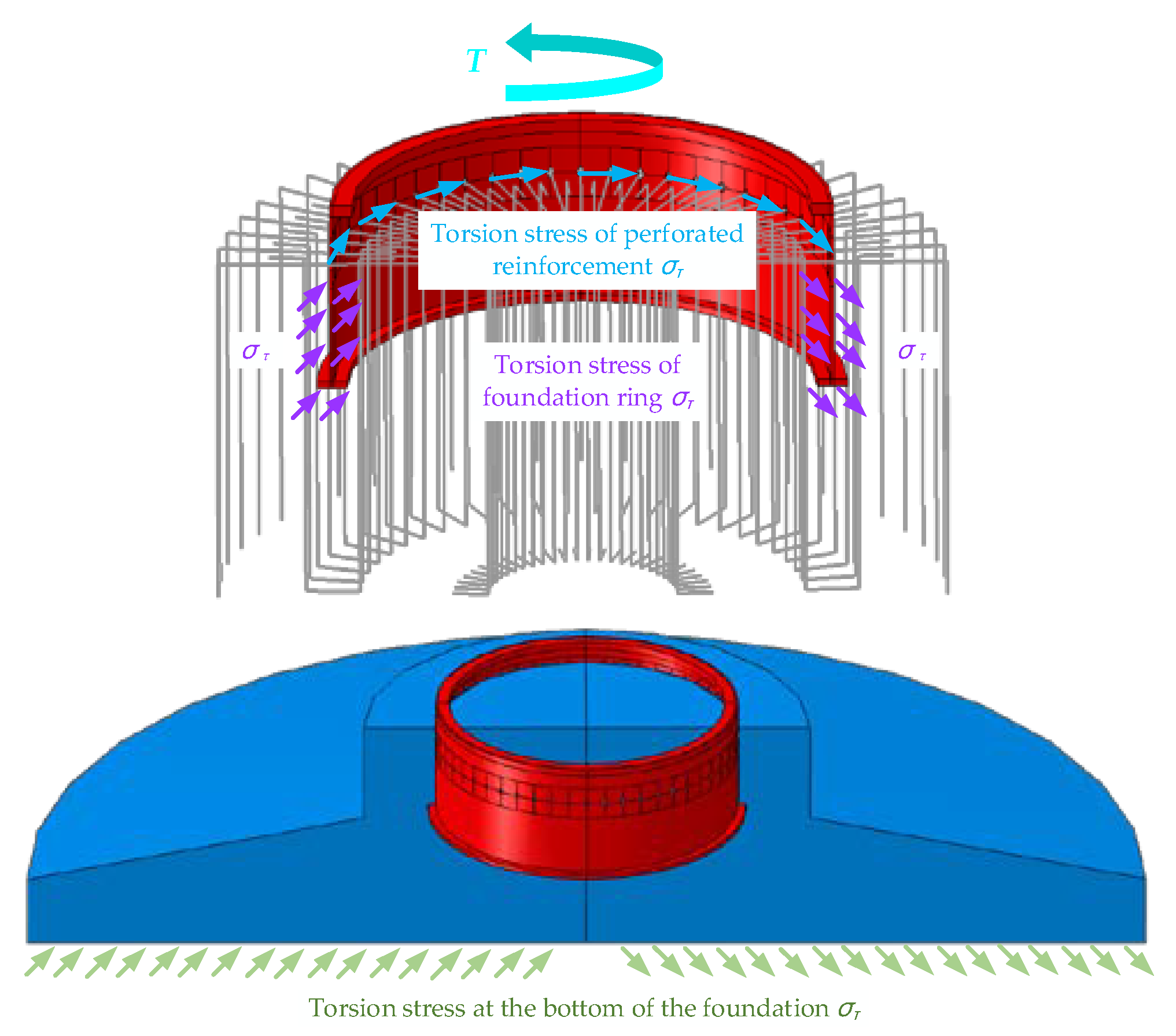
The upper structure transfers the torque load to the top of the foundation ring, then to the internal components of the foundation through the foundation ring, and finally to the base. The foundation resists the upper torsional load by its own frictional resistance to the underlying soil. As shown in
Figure 2, the torque load is transferred to the base structure as follows: top flange of foundation ring → top radial reinforcement (with the surrounding concrete) → sidewalls on the foundation ring (with the surrounding concrete) → foundation ring flange (with the surrounding concrete). In this process, the main component responsible for the transfer process is the foundation ring: one part of the load is shared by the top radial reinforcement, while the other part is further passed downwards.
In the design process, the effect of top radial reinforcement on the antipull capacity is mainly considered, excluding its effect on the antitorsional bearing capacity of the foundation. This is mainly due to the fact that there is currently no definite conclusion about the torque load sharing ratio of antipull bars, and the torque load sustained by the foundation is relatively smaller. However, the load during the actual operation of the foundation ring infrastructure is a composite load, i.e., T–V–H–M, of which the torque load also has a great influence on the stress and force transfer mechanism.
2.2. Torque Load Measurement Method
The torsion deformation of the circular shaft will occur under the torque load, which needs to be simplified to a certain degree when calculating its stress distribution. According to the flat cross-section theorem, it is assumed that the cross-section of the circular shaft still remains a circular plane after twisting and the original radius remains a straight line.
In this experiment, the torque load on the foundation ring was measured using the elastic shaft strain measurement method, i.e., when the circular shaft is subjected to the torque load, the cross-section is subjected to shear stress, and the maximum tensile stress and compressive stress are generated in the direction at an angle of 45° to the axis, and their values are equal to the maximum shear stress on the original section.
The strains along the
and
directions are
where
E is the elastic modulus of the material, and
μ is Poisson’s ratio.
Based on the mechanics of the materials, the following relation can be obtained:
As for the physical relationship and stress distribution, Hook’s law is applied, i.e.,
The calculation formula for torque load
M is as follows:
For a hollow section circular shaft, the calculation formula for its torsion section coefficient
Wp is as follows:
where
is the ratio between the inner and outer diameters of the same section.
2.3. Design and Fabrication of the Experimental Scale Model
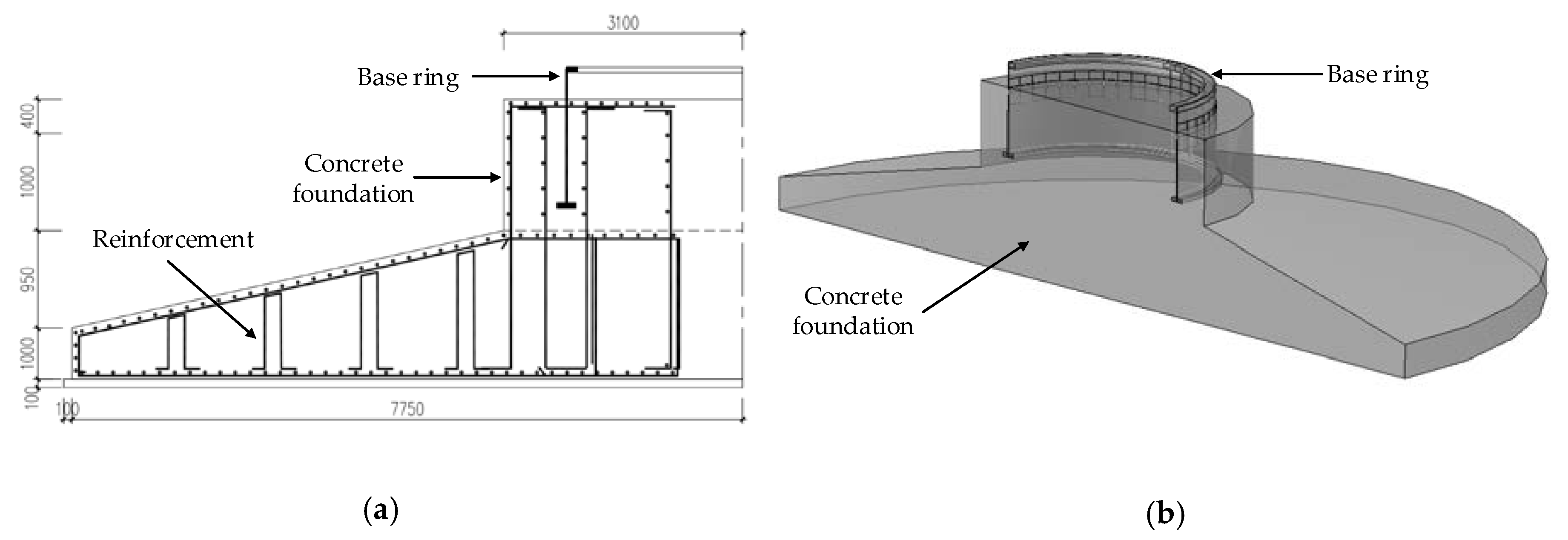
To study the torque transfer mechanism in a foundation ring wind power expanded infrastructure, a 1:3 scale model test on a 1.5-MW onshore wind power infrastructure with a 70-m tower was carried out. Considering the effects of factors (e.g., foundation ring depth, thickness of the bottom flange, and concrete strength) on the bearing capacity of the foundation, the inherent mechanism was analyzed in detail. The size of the original 1.5 MW wind turbine foundation is shown in
Figure 3.
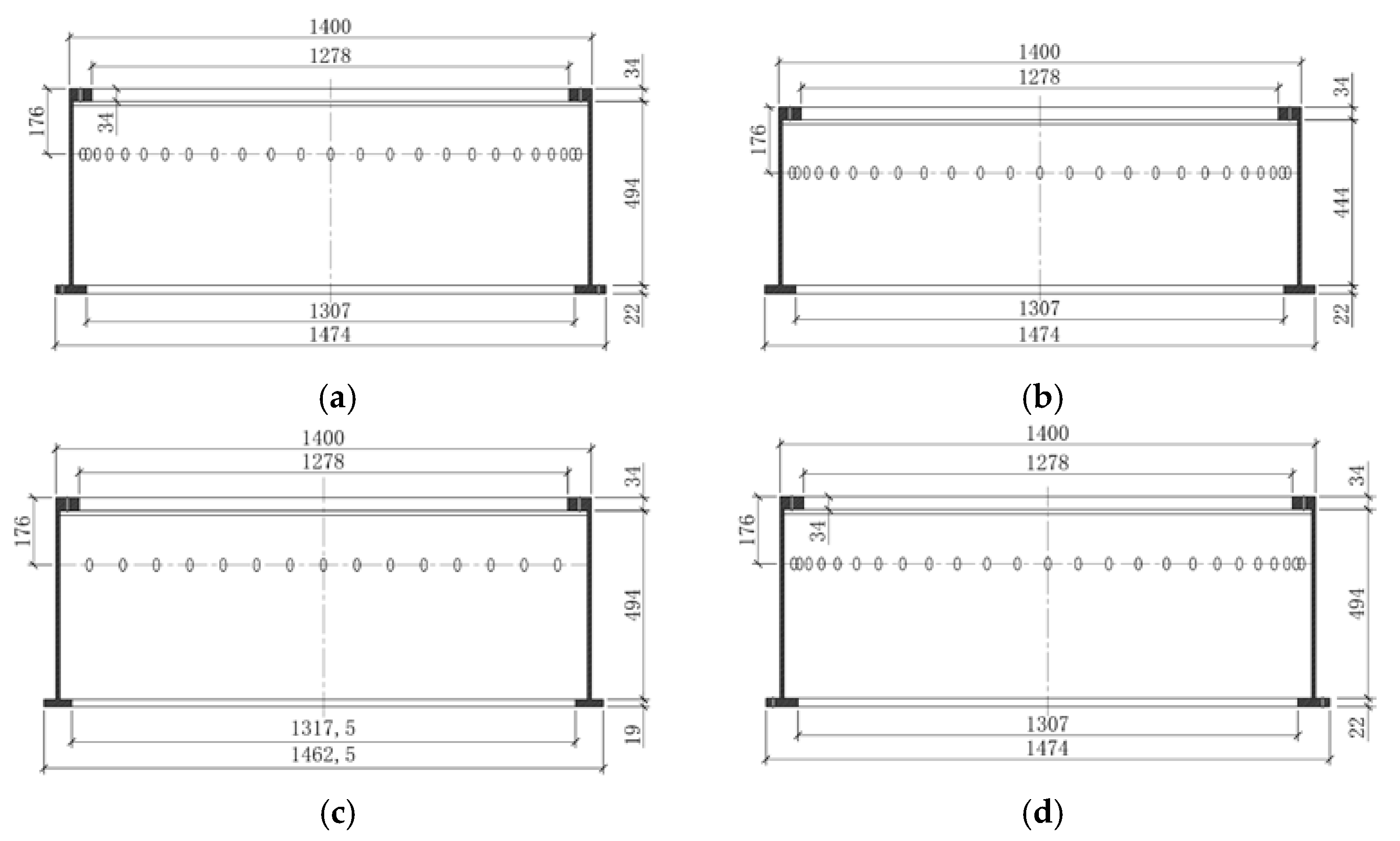
Considering that there is a certain degree of discretion in the performance of the concrete structure, to obtain the system’s experimental data while combining the actual onsite conditions, some parameters of the original drawings should be adjusted, e.g., reducing the foundation ring depth, the thickness of the foundation ring flange, and the strength grade of the concrete. According to the same ratio of 1:3, four scale models were fabricated (see
Table 1), and their monitoring devices were installed.
In this batch of scale model tests, the geometric similarity ratio
, material of the same intensity was used, i.e., the elastic modulus similarity ratio
, and the density similarity ratio
1. The model similarity theory was strictly followed, and similar criteria for other physical quantities can be obtained using the dimensional analysis method, as listed in
Table 2 [
33,
34,
35].
When selecting the foundation ring and reinforcement, the primary scale, based on the basic scale, is selected. Then, the plate thickness and diameter that are closest to the calculated values are selected. The prototype size of the foundation ring and steel reinforcement, as well as the calculated scale size and the actual size of the model, are shown in
Table 3. Note that the foundation ring plate thickness and steel reinforcement diameter can only be chosen from existing models on the market, while the basic ring components and opening sizes can be laser cut and processed to meet the requirements for model size in practice.
Four scale models were fabricated, as shown in
Figure 4.
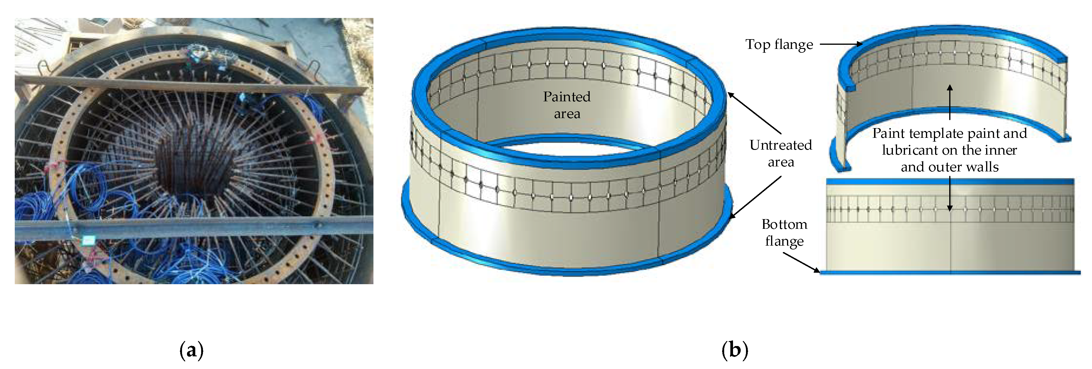
Considering that the research object of this paper is the foundation ring, only the pillars and some concrete in the vicinity were built. The column and pressure beam templates were made with steel mold, the steel bars were fabricated according to design drawings, the strain gauges and pressure boxes were installed at the corresponding positions of the foundation ring, and the reinforcing bars and the concrete meter were installed at the corresponding positions of steel bars. Lastly, concrete pouring was conducted after the foundation ring had been located. In order to eliminate the bonding effect between the sidewall and the concrete, formwork paint was applied to the sidewall of the foundation ring, as shown in
Figure 5b.
In the design process, it is generally believed that the torque load on the top of the foundation ring is all borne by the bottom flange of the foundation ring, together with the top radial reinforcement. The adhesion between the sidewall of the foundation ring and the concrete is not considered but taken as a safety reserve. In order to be consistent with the basic design assumptions and considering that the objective of this paper is to study the distribution ratio of the torque load between the radial reinforcement on the top of the foundation and the bottom flange of the foundation ring, the inner and outer sides of the sidewall were painted with template paint and lubricant during fabrication. Notably, lubricating oil was applied as much as possible to eliminate the adhesion between the sidewall and the concrete, as shown in
Figure 5b. However, the bonding effect cannot be completely eliminated in practice.
2.4. Torque Loading Experiment and Arrangement of Measurement Points
2.4.1. Loading Scheme for Torsion Experiment
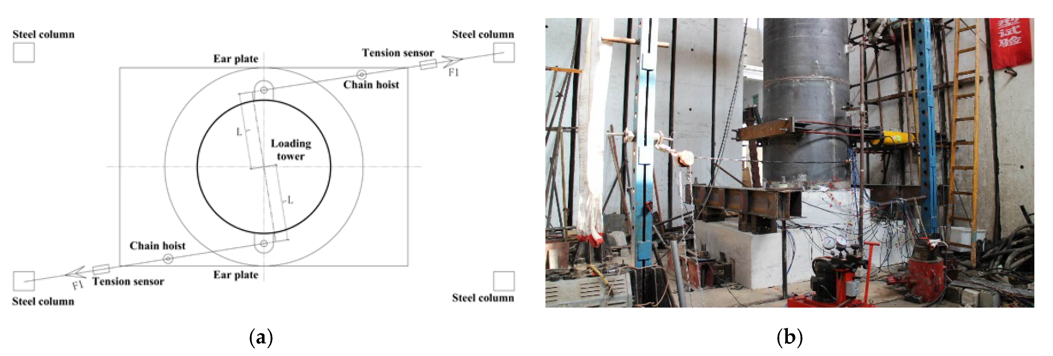
For the torque load
T on the top of the foundation, in light of the actual site conditions in our structural laboratory, the load was applied on the scale model by chain hoist, wire rope, tension sensor, and the surrounding steel columns. Here, the loading point was located at the lifting lug on the bottom of the tower department. The loading devices and arrangement mode are shown in
Figure 6.
In
Figure 6,
T on the foundation ring can be calculated as
where
F1 is the unilateral actual load that should be applied, and
L is the distance from the loading point to the center of the loading tower.
Then,
F1 can be calculated as follows:
To study the transfer mechanism of the internal torque load in the foundation ring expanded foundation, the torque loading test was carried out after the installation of the four model specimens. Through the arrangement of sensors, the stress state of each component inside the foundation was measured, thus obtaining the transfer process and mechanism of the torque load. When carrying out the torque load test alone, the load was applied using the graded loading method, as listed in
Table 4.
According to
Table 4, graded loading was applied on each specimen. In the case of single-torque loading, two horizontal jacks were required to be released to ensure that the loading tower was free from constraints. The vertical load simulates the self-weight of wind turbines and the support system by a real wind power infrastructure. Therefore, when a single-torque load is applied, this load cannot be ignored, and the vertical load should be kept stable during loading.
2.4.2. Arrangement of Foundation Ring Strain Measurement Points
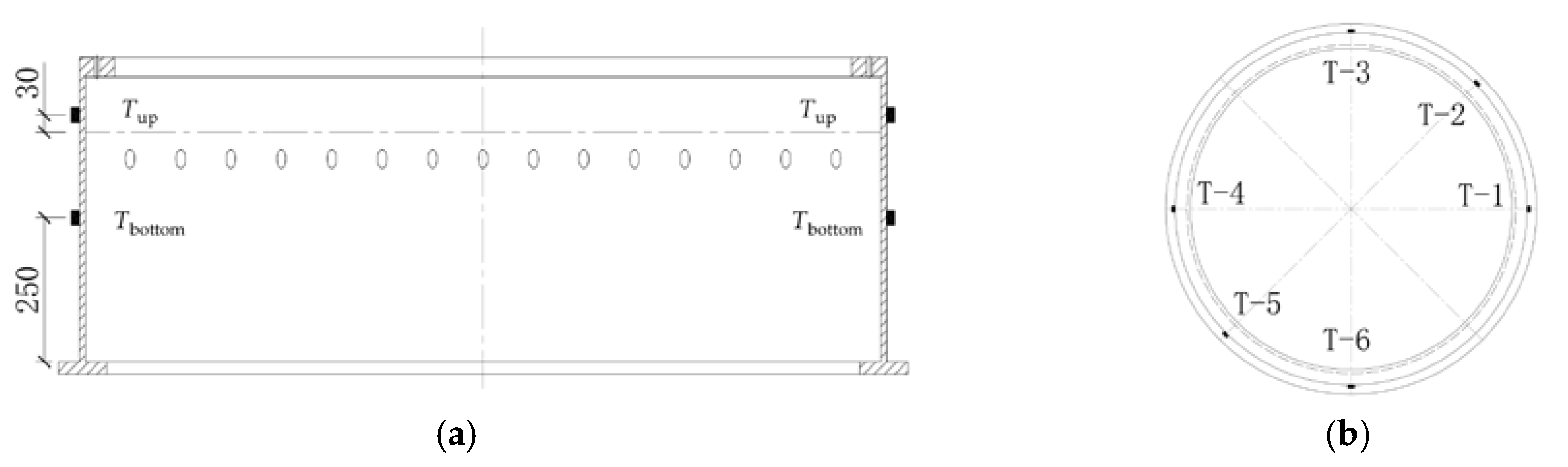
To study the stress distribution on the sidewall of the foundation ring while taking into account the ease of lead-out, two layers of strain gauge measuring points were installed in the circumferential direction on the outer side of the foundation ring. These layers were buried in the concrete, and six measuring points were symmetrically set on each layer, as shown in
Figure 7.
3. Analysis of Torque Load Transfer Mechanism
3.1. Standard Scale Model
In this test, the strain gauge on the sidewall of the foundation ring is located on the outer side, so the measured torsional strain (stress) should be the maximum. Through the above analysis, the theoretical shear stress in each specimen under torsional load can be calculated. Based on the mean value of shear stress on different cross-sections, the transfer mechanism of the torsional load can be further analyzed.
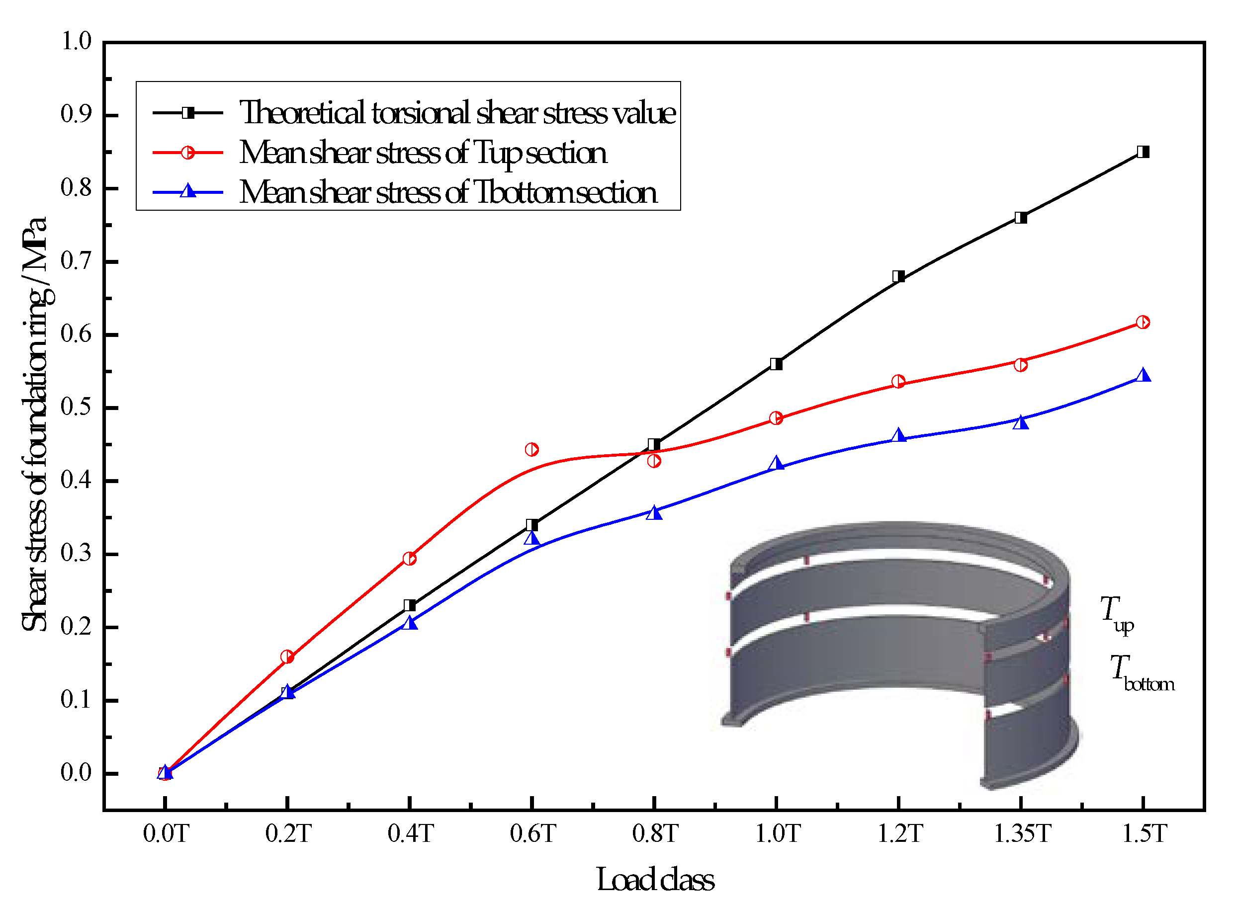
Here, the standard specimen ZT-1 is taken as an example. To avoid the influence of stress concentration at the opening of the foundation ring, the corresponding stress measurement point was arranged at a certain distance from the opening. The stress at each measurement point on the flat cross-section above or under the opening was analyzed, as shown in
Figure 8.
Consider that when the experimental model was being made, the isolation measures of the template paint and lubricant had been applied to the sidewall of the foundation ring. Assume that the adhesion between the foundation ring sidewall and the concrete is small at this time. The calculation method for the torque load on the three sections is as follows:
(1) Actual torque load applied
The actual torque load was applied step by step, according to
Table 4. The actual applied tension value was measured by two tension sensors, and then the actual applied torque load was calculated according to Equation (10).
(2) Torque load transferred to the foundation ring
On the outer surface of the foundation ring, at a certain distance upwards from the top radial reinforcement, a 45° right-angle strain rosette measurement point on the top of the first layer was set, and the measured strain value can be calculated according to Equation (8).
(3) Actual torque load on the bottom flange of the foundation ring
On the outer surface of the foundation ring, at a certain distance downwards from the top radial reinforcement, a 45° right-angle strain rosette measurement point at the bottom of the first layer was set, and the torque load of this section can also be calculated.
At this time, it can be considered that the torque load difference between
Tup and
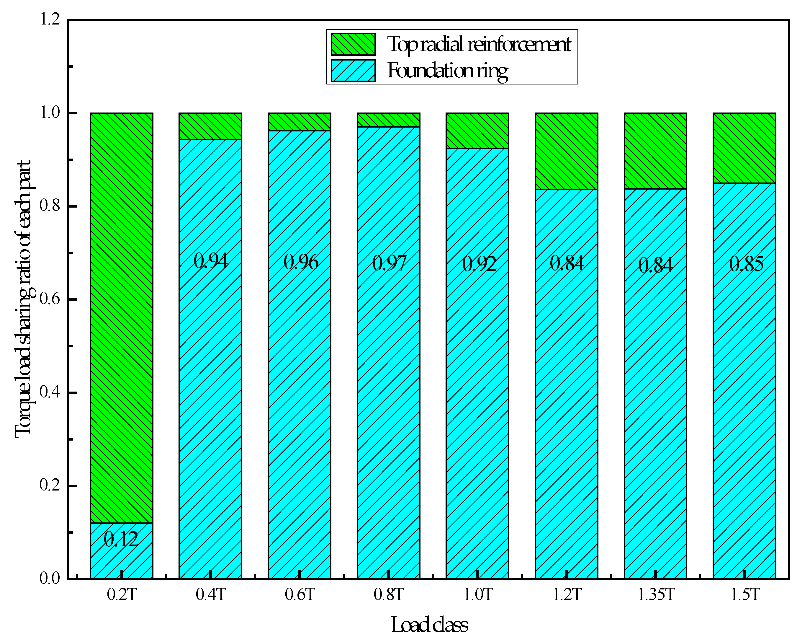
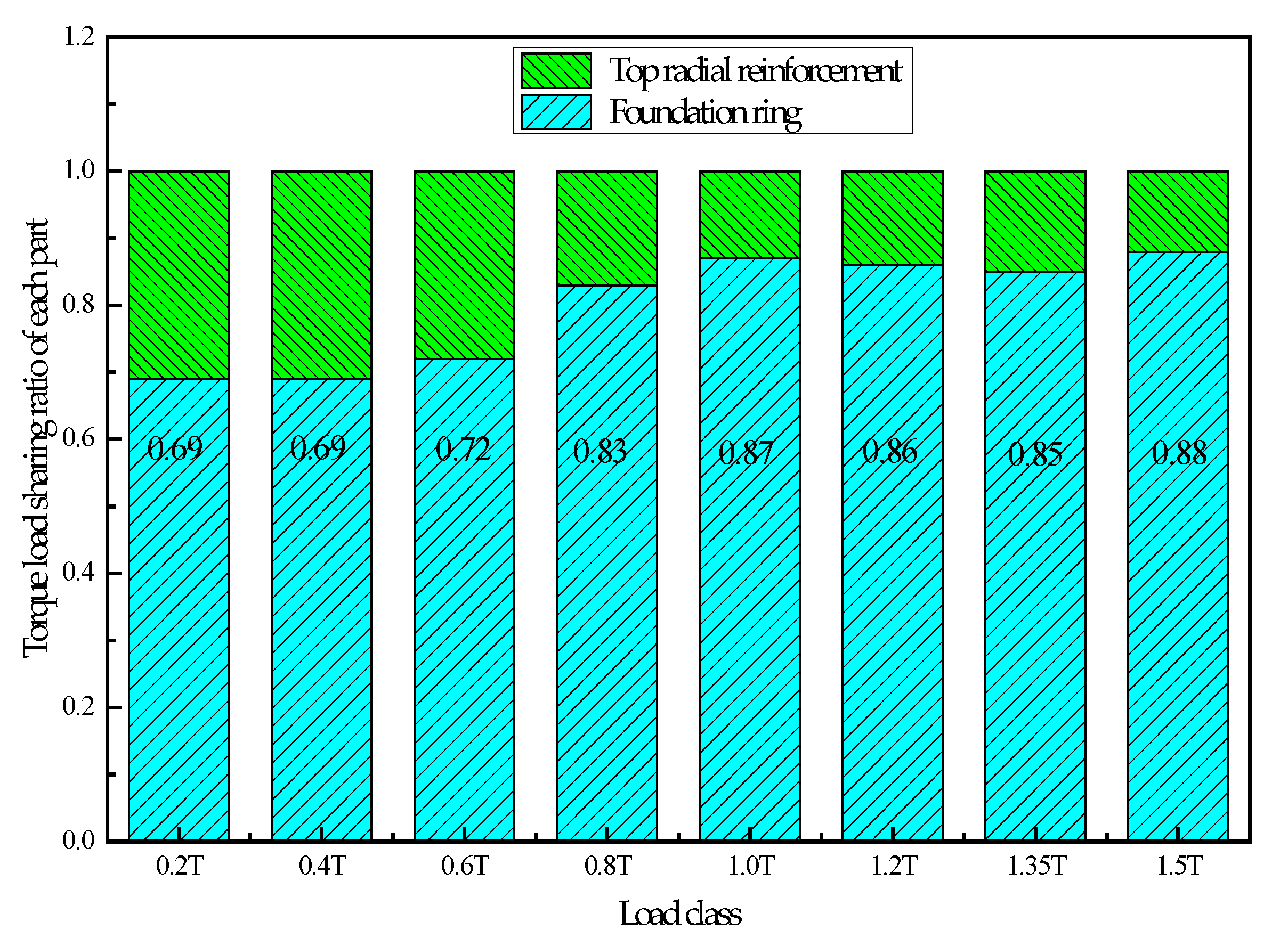
Tbottom is shared by the top radial reinforcement. Using this simplified analysis method, the forces of top radial reinforcement and the foundation ring of ZT-1 during the whole loading process can be summarized, as shown in
Figure 9.
Under the torque load, the foundation ring shares the main torque load except at the first stage. Under 0.4–1.0 T, the foundation ring shares about 90%; after 1.0 T, the ratio changes to about 85%. After the torque load is transferred through the top radial reinforcement to the foundation ring, it is further transferred to its lower part. As a result, the top radial reinforcement on the top layer shares only a small part.
3.2. Influence of Foundation Ring Depth
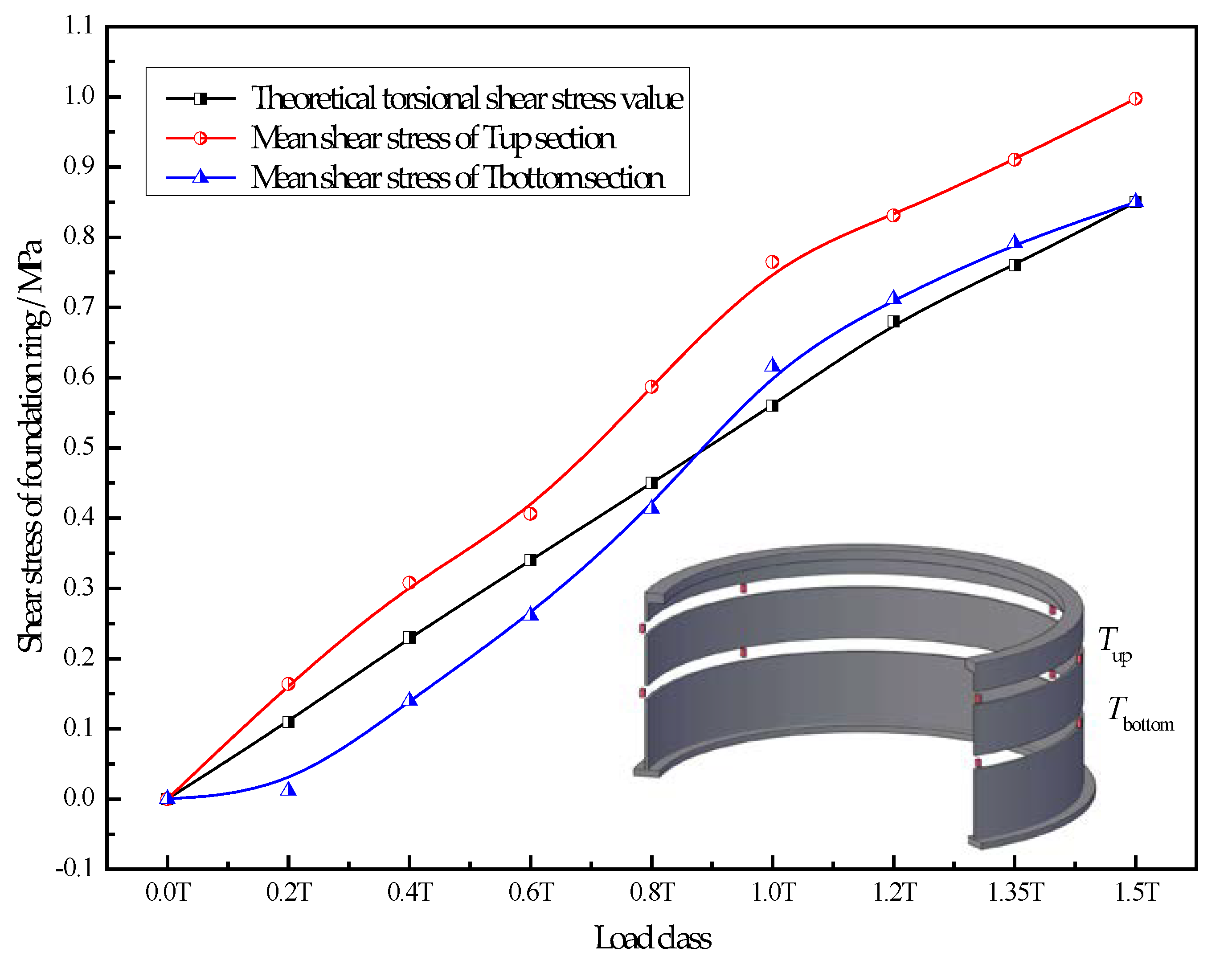
Using the same analysis method, the torque load transfer process of specimen ZT-2, with a reduced foundation ring depth, was analyzed. The changes in torsional shear stress at the measurement points on the planes above or below the opening of ZT-2, under various loads, are shown in
Figure 10.
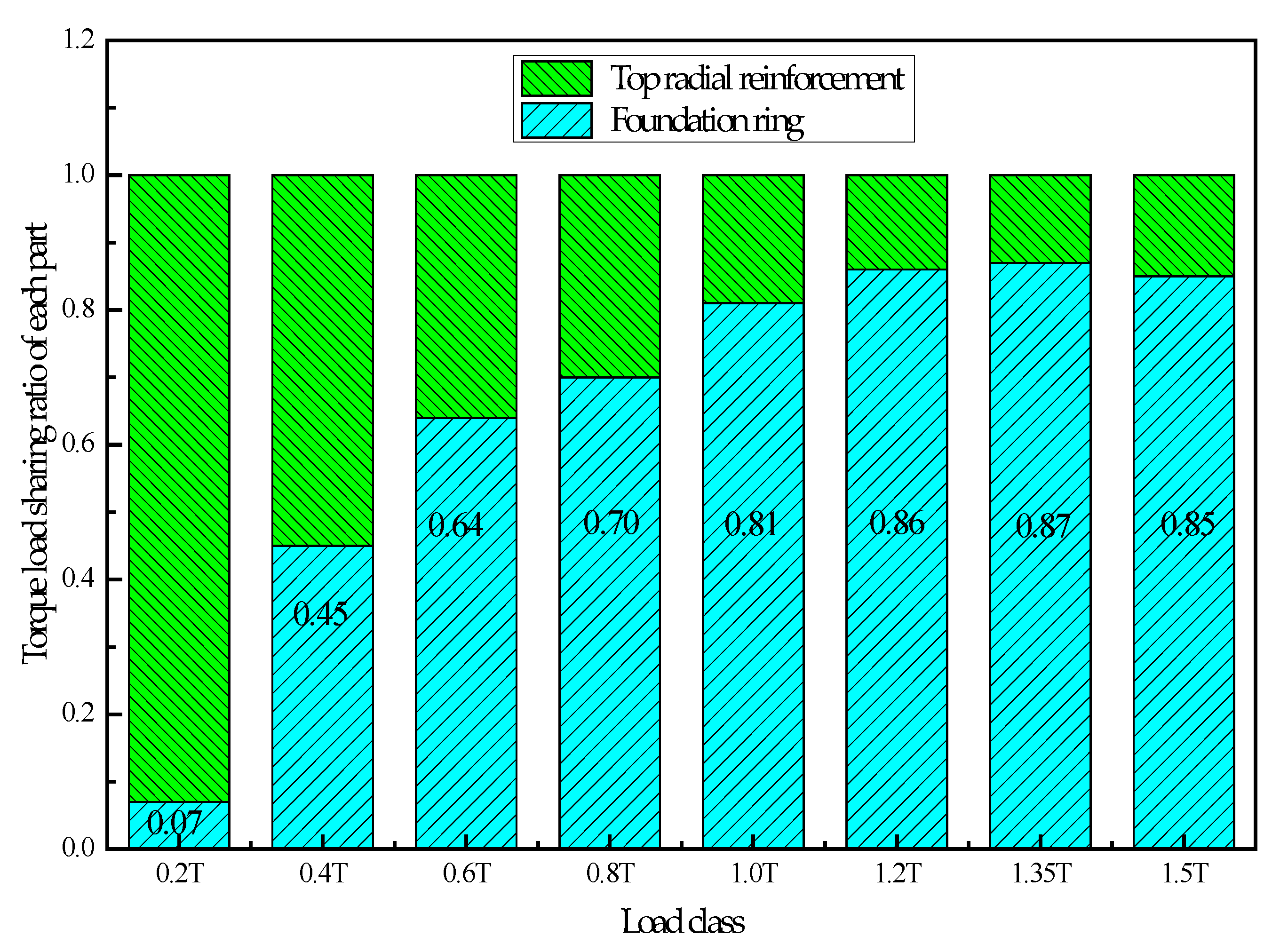
Using the simplified analysis method, the forces in the top radial reinforcement and the foundation ring of ZT-2, during the whole loading process, were analyzed, as shown in
Figure 11.
The variation trend of ZT-2 is consistent with that of ZT-1. Under the working conditions of the 1st-level load, the torque load sharing ratio of the foundation ring is smaller; afterward, the overall trend increases and tends to be stable. In addition to the conditions of the 1st-level load, the foundation ring still shares the main torque load. Within 0.4–0.8 T, the torque load sharing ratio increases rapidly. After 1.0 T, the foundation ring shares about 86%, which is basically the same as that of ZT-1. The torque load is mainly transferred downwards and around the foundation ring, while the top radial reinforcement in the top layer only shares a smaller part.
Combined with the results of the previous analysis, the stress change in the rest reinforcement around the foundation ring is limited, so it can be inferred that the torque load is mainly sustained by the sidewall of the foundation ring, as well as the bonding force between the bottom flange and the surrounding concrete. Under 1.5 times the limit load, there is no obvious stress damage to the foundation ring or to the surrounding concrete. When the foundation ring depth was reduced by 13%, the load transfer process and the mechanism of the torsional load on the foundation ring were not obviously affected. The torque load was still mainly sustained and transferred by the foundation ring. After 1.0 T, the torque load sharing ratio of the top radial reinforcement is about 14%.
3.3. Influence of Bottom Flange Width on Foundation Ring Bottom
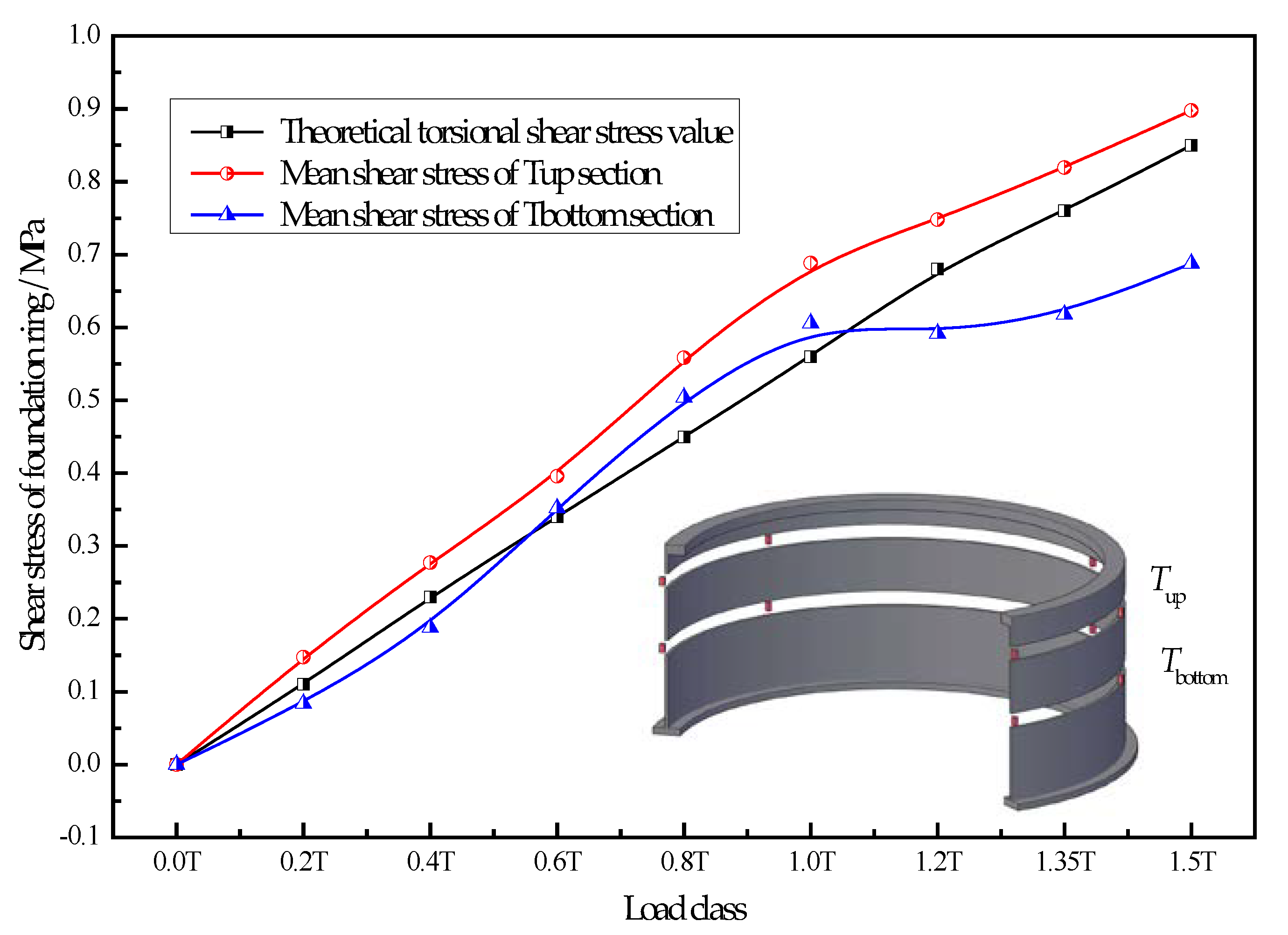
Using the same analysis method, the torque load transfer process of specimen ZT-3, with reduced flange width and thickness of the foundation ring bottom, was analyzed. Under various loads, the stress changes at the measurement points on the planes above or under the opening of specimen ZT-3 were obtained, as shown in
Figure 12.
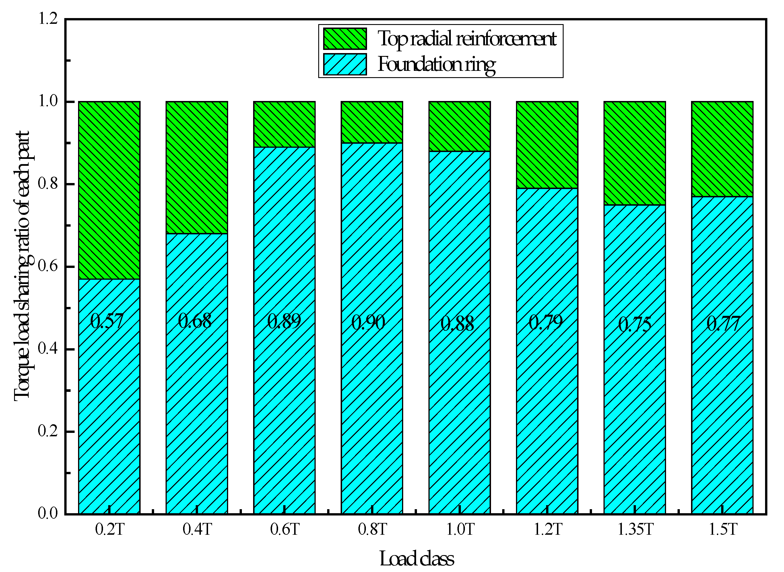
Using the simplified analysis method, the force in the top radial reinforcement and the foundation ring of specimen ZT-3 during the whole loading process was analyzed, as shown in
Figure 13.
The torque load is still mainly sustained by the foundation ring, which is the same as those for ZT-1 and ZT-2. The sharing ratio of the foundation ring fluctuates at the early stage and tends to be stable afterward. Under 0.6–1.0 T, about 90% of the torsional load is sustained by the foundation ring. After 1.2 T, this ratio changes to about 78%.
After the width and thickness of the flange on the foundation ring bottom were both reduced by 13%, the load transfer process and mechanism of the torsional load of the foundation ring were not obviously affected, and the torque load was still mainly sustained and transferred by the foundation ring. The top radial reinforcements tend to be stable after 1.0 T, and the torque load sharing ratio is about 22%.
3.4. Influence of Concrete Strength Grade
Using the same analysis method, the torque load transfer process of specimen ZT-4, with a reduced concrete strength grade, was analyzed. Under various loads, the stress changes at the measurement points on the plane above or under the opening of specimen ZT-4 were obtained, as shown in
Figure 14.
Using the simplified analysis method, the force in the top radial reinforcement and the foundation ring of specimen ZT-4 during the whole loading process was analyzed, as shown in
Figure 15.
The torque load on specimen ZT-4 is mainly sustained by the foundation ring; within 0.2–0.6 T, the foundation ring shares about 70%; after 0.8 T, the region is stable, and the foundation ring shares about 85%.
The concrete strength grade of standard ZT-1 was C35. After it was reduced to C25, as in specimen ZT-4, the load transfer process and the mechanism of torsional load in the foundation ring were not obviously affected, and the torque load was still mainly sustained and further transferred by the foundation ring. The top radial reinforcement tends to be stable after 0.8 T, and the sharing ratio is about 15%.
3.5. Comparative Analysis of Test Results
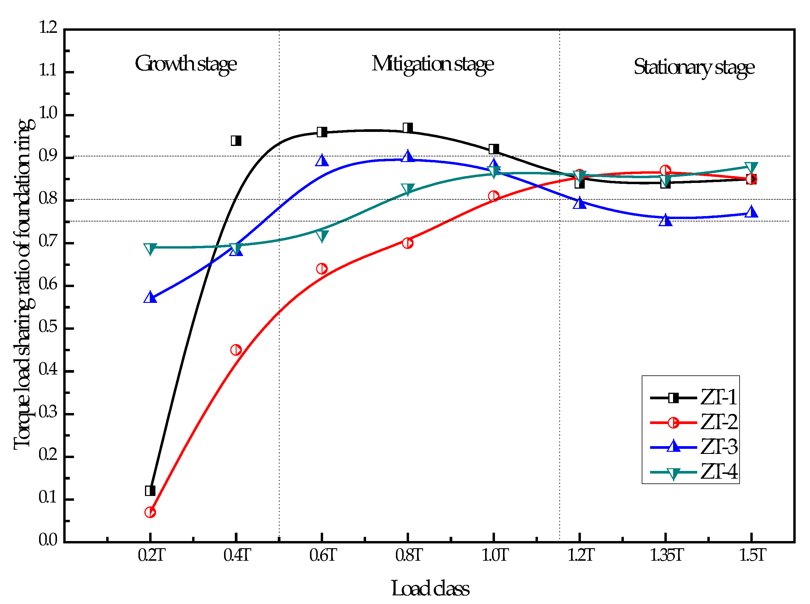
The shear stress in the foundation rings of the four specimens under the torque load was analyzed, and the variation in torsional shear stress in each specimen was obtained. The changing trends of shear stress in each specimen under the torque load were compared, as shown in
Figure 16.
Under the torque load, the characteristics of shear stress in the foundation ring of the four specimens were more consistent, which can be divided into the following three stages.
- (1)
Growth stage: within 0.2–0.5 T, the shear stress shared by the foundation ring of each specimen fluctuated slightly, which was a common characteristic at the initial loading stage. Nevertheless, the growing trend was relatively rapid as a whole.
- (2)
Mitigation stage: within 0.5–1.1 T, the growing rate of the shear stress sharing ratio (60–95%) of the foundation ring in each specimen slowed down.
- (3)
Stationary stage: within 1.1–1.5 T, the shear stress sharing ratio (75–90%) of the foundation ring in each specimen tended to be stable, with an average value of about 80%.
Experimental results show a certain degree of dispersion, especially at the initial loading stage. This is due to two reasons. First, the torque load itself was too small. Second, the concrete material itself had greater dispersion, even though the four concrete experimental scale models were made and poured in the same batch. However, the overall trends of experimental results were relatively consistent, reflecting the influences of various parameters on the torque load transmission. The torque load shared by the foundation ring fluctuated initially and tended to be stable afterward.
The torque load was mainly sustained by the foundation ring and further transferred downwards, while only a small part was sustained by the top radial reinforcement. At the stationary stage, after the width and thickness of the bottom flange were both reduced by 13%, the torque load sharing ratio of the foundation ring decreased most obviously. On the contrary, the effects of the reduction in the foundation ring depth and strength grade of the base concrete were not obvious. The top radial reinforcements shared about 15–22% of the torque load, most of which were sustained and further transferred by the foundation ring. This part of the torque load had less effect on the force in the top radial reinforcement.
During this experiment, only the vertical self-weight load and torque load were applied. In order to study the transmission path of the torque load in the foundation by only one single factor, template paint and lubricant were applied to the sidewall of the foundation ring during its fabrication. However, even after this treatment, there was still a certain amount of adhesion and friction therein. Therefore, at the early and middle stages of torque loading, most of the torque was borne by the residual cohesive force of the sidewall and the top radial reinforcement, while the torque load transmitted to the bottom anchor flange of the foundation ring was relatively small. With the continuous increase in torque load, after gradually eliminating the bonding force between the sidewall of the foundation ring and the residual concrete, the torque load transferred to the anchor flange at the bottom of the foundation ring gradually increased.
4. Conclusions
Based on the designed torque loading system and the proposed measurement method, four specimens subjected to torque load were tested, and the following conclusions were obtained.
- (1)
The method of applying template paint and lubricant on the sidewall of the foundation ring can effectively reduce the adhesion between the two parts, thus providing technical conditions for a single-factor stress analysis of the foundation under torque load.
- (2)
The ratio of the torque load borne by the foundation ring increases with the growing torque load, which can be divided into the growth, mitigation, and stationary stages.
- (3)
When the torque load is small, it is mainly borne by the adhesion force of the sidewall of the foundation ring and the top radial reinforcement. When it is large, it is gradually borne by the anchor bottom flange of the foundation ring.
- (4)
At the middle and late stages of loading, the radial reinforcement on the top of the foundation shares about 20% of the torque load, while the foundation ring bottom flange shares about 80%.
- (5)
When the width and thickness of the bottom flange were both reduced by 13%, the proportion of torque load borne by the foundation ring decreased most obviously. In comparison, the reduction in the embedded depth of the foundation ring and the concrete strength had less effect.
Finally, it needs to be clarified that the main purpose of this article is to study the transmission mechanism of the torque load in the wind turbine foundation, take certain loading measures, and reduce friction measures. However, this method can only minimize the influence of other loads on the torque load, and cannot completely eliminate the influence of the bending moment load.


