Article

Laboratory Investigation of the Temperature-Dependent Mechanical Properties of a CRTS-Ⅱ Ballastless Track-Bridge Structural System in Summer

School of Civil Engineering & National Engineering Laboratory for High Speed Railway Construction, Central South University, 68 South Shaoshan Road, Changsha 410075, China
*
Author to whom correspondence should be addressed.
Appl. Sci. 2020, 10(16), 5504; https://doi.org/10.3390/app10165504
Submission received: 17 July 2020 / Revised: 6 August 2020 / Accepted: 6 August 2020 / Published: 9 August 2020

Abstract

:
To study the mechanical properties of the China Railway Track System type II (CRTS-II) ballastless slab track structure, a 1/4-scale specimen of a CRTS-II slab ballastless track-32-m standard prefabricated simply supported box girder bridge with three spans and two high-speed railway lines was developed. The mechanical properties of the structure under the action of daily natural temperatures were studied under the natural environmental conditions. The structural strain and relative interlayer displacements were analyzed. The results show that the temperature of the CRTS-II ballastless track-bridge structural system changes periodically every 24 h. The strain of the structural layers of the track system first increases and then decreases sinusoidally, and the internal strain of the track system lags along the vertical depth direction. The relative displacement between the layers of the ballastless track bridge structure system increases with the increase in temperature. The extreme value of the vertical relative displacement appears between the track bed and the bridge at section 1/4 in the span, so it should be paid attention to by the maintenance personnel. Due to the constraint of the shear slots, the structural strain and relative displacement at the fixed end near the shear slots are smaller than those at the sliding end. The mid-span deflection is the largest, and the overall deflection during the cooling phase is more significant than that during the heating phase.

1. Introduction

With its advantages, such as high smoothness, high stability and good durability, the CRTS-II ballastless slab track has been widely used in China [1,2,3]. However, under the joint action of construction, the natural environment, external loading, self-aging, and other factors, the CRTS-II ballastless track system will experience a series of issues, such as interlayer separation [4], longitudinal irregularities [5], and track slab warping [6]. Existing studies show that the effects of various temperature loads, such as annual temperature loads, sudden temperature drops, and daily temperature loads, cannot be ignored [7,8,9,10].
The ballastless track system in the natural environment is affected by the overall rise and fall of the temperature and the temperature gradient along with the structure height [11,12,13]. The former will cause expansion deformation, and the latter will cause flexural deformation of the track system. Chinese and international scholars have achieved much research work on the time-dependent temperature field law, mechanical properties and failure mechanism of ballastless track systems under temperature loads [14,15,16]. Dai Gonglian [17,18,19] et al. embedded temperature sensors in ballastless tracks on curved bridges, performed long-term monitoring of the temperature field, and obtained the time-dependent temperature field law of longitudinally connected ballastless slab track-bridge systems under various natural conditions, such as extreme summer and cold winter temperatures, as well as the vertical and horizontal temperature gradient load modes. Based on meteorological principles, Liu Fushan [20] established a three-dimensional finite element analysis model of the CRTS-II ballastless track temperature field and studied the time-dependent law and the influence of various factors on the temperature field of ballastless tracks. Based on the interface cohesive zone model, Gao Liang et al. [21] developed a three-dimensional finite element model of slab track and revealed the temperature characteristic of the slab track to studied the deformation and interface stress of the slab track under daily changing temperature, which provided information to the control of early interface damage. Wang senrong et al. [22] established a calculation model of the temperature warping stress according to the temperature measurement results of the track slab and analysed the warping stress and displacement of the track slab. P. Salcher et al. [23] established a stochastic model of the environmental seasonal temperature influence on the structure, which can accurately predict the frequency change of bridge structures under natural temperature changes and provides a basis for the reliable research of train-bridge interaction problems. Zhu Jinsong et al. [24] studied the vertical and lateral temperature distribution of the track-bridge system under the shadow by establishing a finite element model and formula fitting, which provided a reference for the formulation and improvement of relevant specifications.
In summary, most of the existing studies use finite element software for numerical simulation, and there are few related experimental studies; thus, it is difficult to fully consider the actual interlayer contact characteristics. In addition, the existing research has mainly focused on the temperature field of the track system and the mechanical properties of the track slab. The laws of the strain and relative displacement between the track layers under the action of natural temperatures are still not addressed. Most of the researches were carried out on a single structural layer to study its warping deformation law and damage mechanism, without fully considering the beam body, shear cogging and its own restraint effect. Furthermore, there is no systematic discussion on the mechanical properties and the cooperative performance of the CRTS-II ballastless track system on the bridge under natural conditions. At the same time, most of the existing research focuses on the temperature field and mechanical properties of the orbital system, where solar radiation and thermal convection work together. There is little discussion on the ballastless track system that only considers the influence of air temperature under the shielding effect. Therefore, a 1/4-scale model of the CRTS-II slab ballastless track-32-m standard prefabricated simply supported box girder bridge with three spans and rail and fasteners were constructed simulating the natural environment without direct sunlight in extreme summer conditions, and the mechanical performance of the CRTS-II ballastless track system under daily temperature action was studied. The highest temperature of the test day was 38 °C, and temperature, strain and displacement sensors were used for data acquisition. Based on the test results, the strain and the relative displacement between layers of the track system are analyzed, and the corresponding engineering suggestions are put forward. At the same time, the experimental basis is provided for further research on the temperature field, mechanical properties and temperature damage of the structure under the action of temperature.

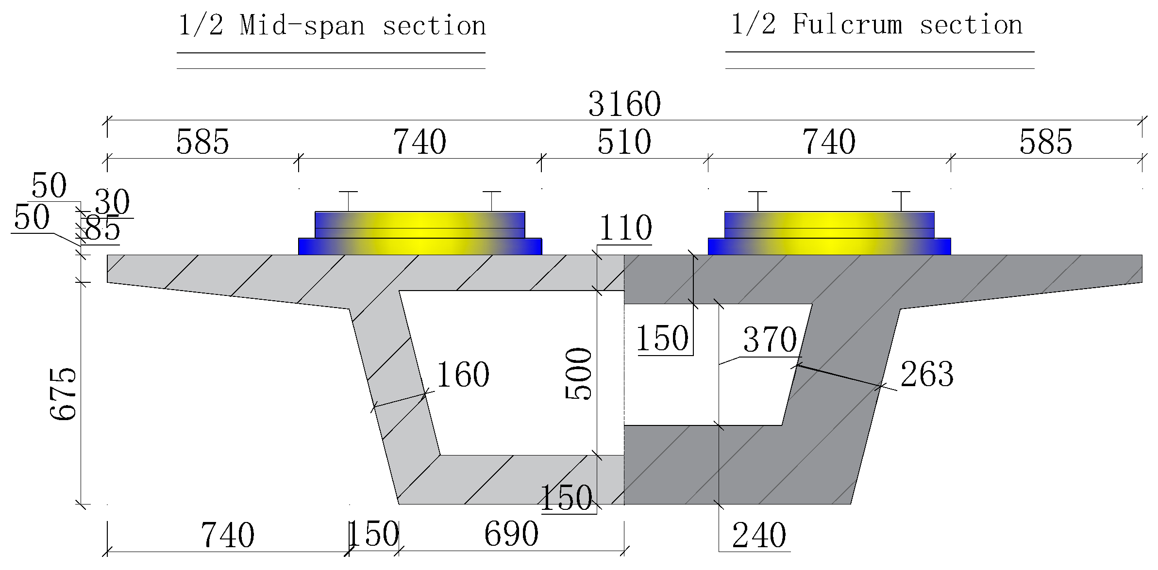
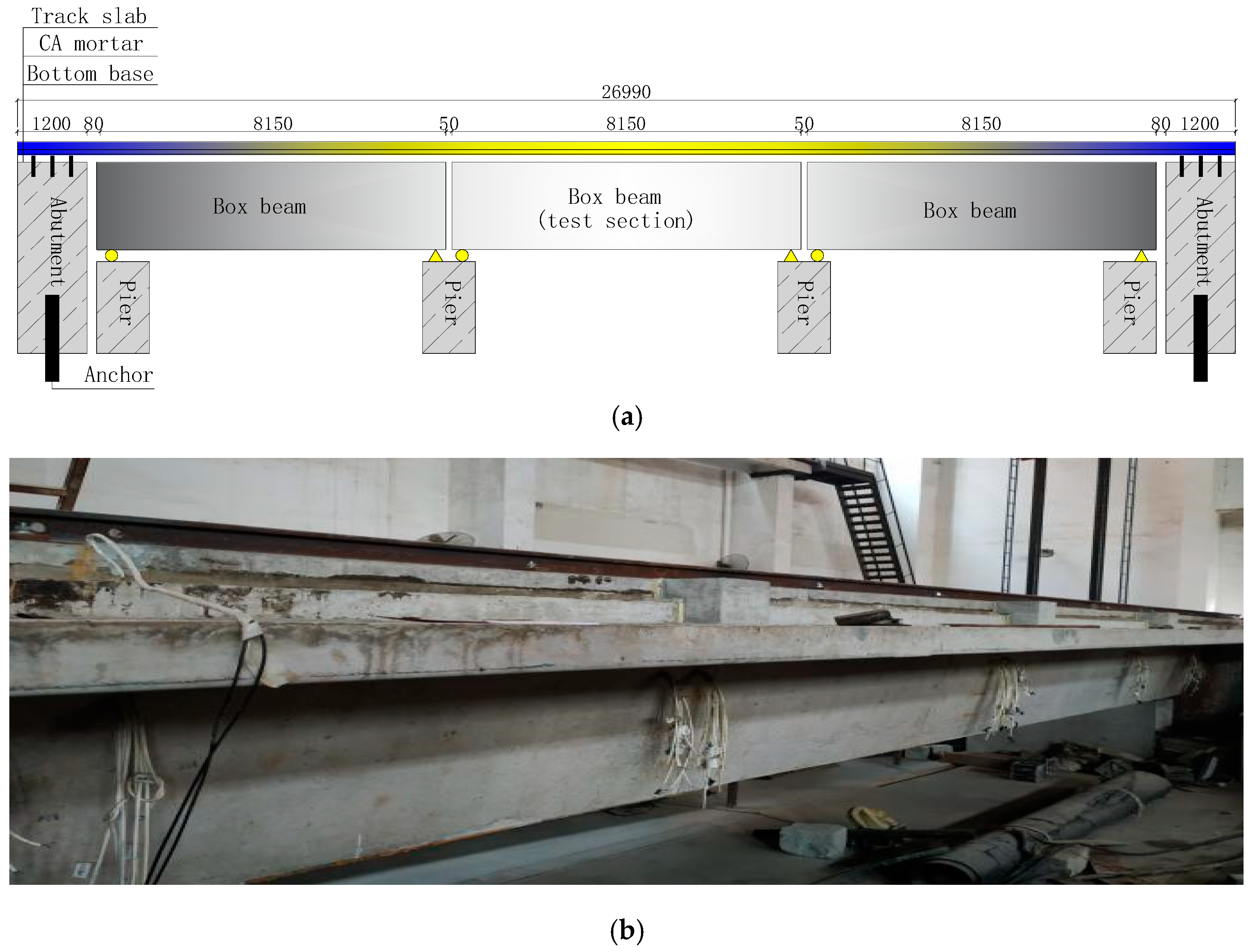
2. Test Model Overview

The prototype structure for this test is a three-span 32-m standard prefabricated simply supported box girder bridge overlaid by a CRTS-II ballastless slab track. The single-span bridge is 32.6 m long, the design span is 31.5 m, and the beam height and top width are 3.052 m and 12.6 m, respectively. Based on the principle of similarity, a 1/4 scaled specimen of the prototype track-bridge structural system is fabricated with materials consistent with that of the prototype structure. The scaled cross-section is shown in Figure 1.
The ballastless track system is composed of a track bed, a CA mortar (cement asphalt mortar) filling layer, a prefabricated track slab, fasteners and rails. To simulate the infinite boundary conditions of the track structure, a three-span simply supported beam is fabricated, as shown in Figure 2, and the middle track-bridge structural system (referred to as the tested beam) is selected for the test. To further ensure the longitudinal continuity of the stress state of the system, 20 tons of heavy solid concrete blocks were cast at both ends of the side spans adjacent to the tested beam. The heavy concrete blocks were anchored with anchor bolts to the foundation, while the track bed was anchored with anchor bars to the heavy concrete blocks. Shear slots embedded in the entire thickness of the track bed were provided at the fixed end of each simply supported beam span [2].

3. Experimental Content and Methodology

3.1. Monitoring Points

During specimen fabrication, fiber Bragg grating (FBG) strain sensors, strain gauges, JMT-36B temperature sensors and 5G10X-series linear displacement gauges are arranged at the predetermined positions of the track system and box girder (of the tested beam). The fixed end section of the tested beam is considered the origin of the span (0 L), and the sliding end section is considered the end of the span (L).

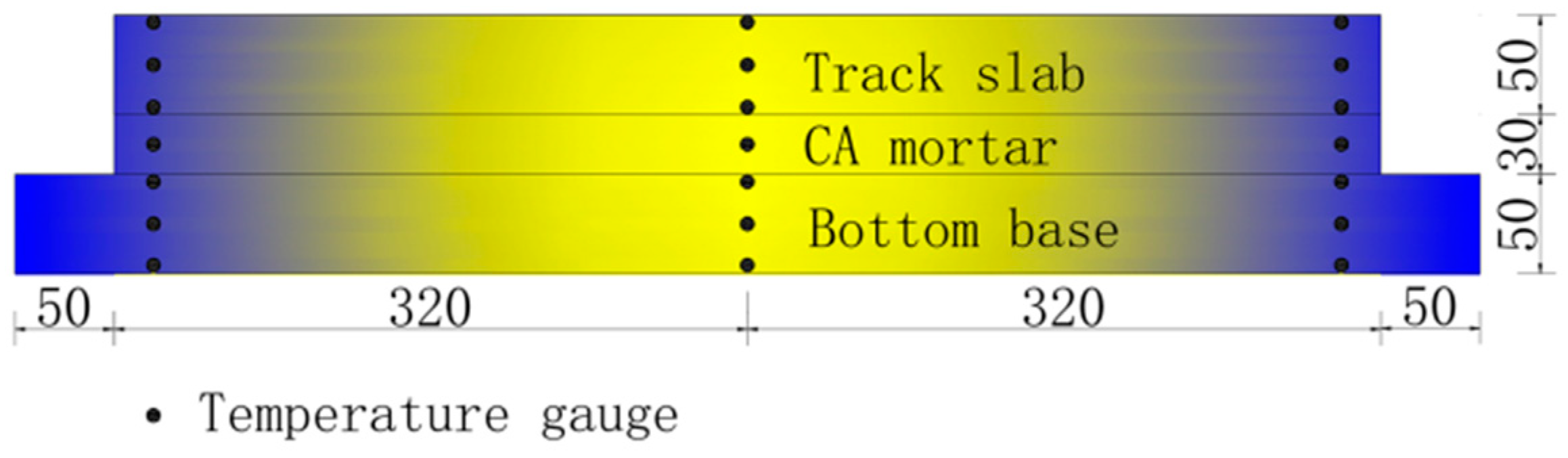
3.1.1. Temperature Measuring Points

A JMT-36B semiconductor temperature sensor is used to measure and collect the temperature of the structure under the action of daily temperatures. The Jmt-36B temperature sensor uses the conductivity of semiconductor (PN junction) to change regularly with the change of temperature. The PN junction is packaged as a chip to achieve high precision, high reliability and high stability of the temperature measurement [25]. At the mid-span section of the tested beam, a total of seven rows of temperature sensors are buried in the upper, middle and lower parts of each layer of the ballastless track system, and the data were collected every 30 min. The specific layout of the measuring points is shown in Figure 3.

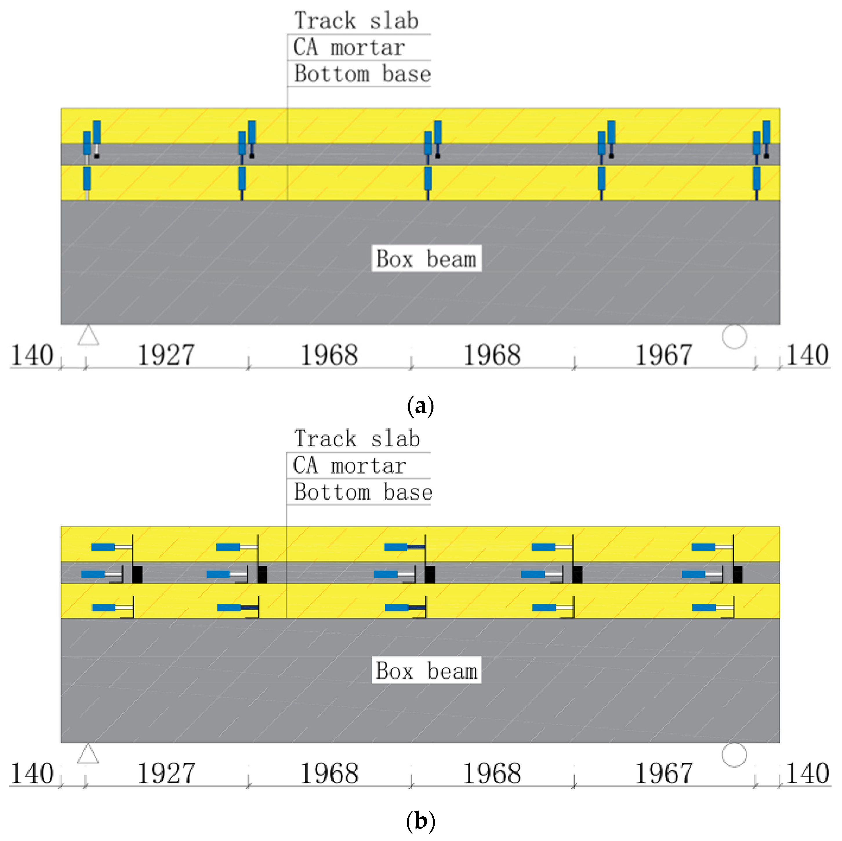
3.1.2. Strain Measuring Points

FBG strain sensors are embedded in the track slab, the CA mortar layer and the track bed at different sections of the tested beam, namely, at 0 L, 1/4 L, 1/2 L, 3/4 L and L. The measuring points are all located on the longitudinal central axis of the track system. The Moi-sm130 FBG demodulator is used for data acquisition and processing, and the data were collected every 30 min at a sampling frequency of 2 Hz. The specific layout of the FBG strain sensor is shown in Figure 4.

3.1.3. Displacement Measuring Points

A 5G10X-series linear displacement gauge is selected to measure the vertical relative displacement, longitudinal relative displacement and deflection of the tested beam, and the DH3820 collector is selected to collect the displacement data, and the sampling frequency is set to 0.01 Hz to ensure that the sampling is more than once every 30 min. The layout section of the displacement measuring points is the same as that of the strain measuring points, as shown in Figure 5. The installation method of the LVDT (Linear Variable Differential Transformer) displacement meter between the structural layers is as follows: To measure the relative displacement between two layers, the base of the LVDT is fixed to steel and attached to one layer with strong structural adhesive, while its top bar is fixed on another steel angle sand attached to the other layer. Relative displacements between the track slab and CA mortar layer, the track bed and box beam, the track slab and track bed and the CA mortar layer and track bed were measured.
The deflection of the bridge structure under the action of temperature is measured by the LVDT displacement gauge. Displacement measuring points are arranged at the support sections of the beam, the 1/4 span section, the 3/4 span section and at the mid-span section of both sides of the concrete box girder transverse section.

3.2. Test Procedure

The test was undertaken in the National Engineering Laboratory of High-Speed Railway Construction Technology of Central South University in Changsha City in August 2019. According to the meteorological monitoring data, the weather was sunny with a high temperature of approximately 38 °C and a low temperature of nearly 30 °C for several consecutive days in which the test day is selected to ensure the representativeness of the collected data. On the day of the test, the laboratory had good ventilation conditions, and the indoor temperature was essentially the same as that of the natural environment. At 9:00 on the day of the test, the initial state of the specimen and the initial temperature of the environment were collected, and the data were collected every 30 min from 9:00 to 9:00 on the next day (24 h).

4. Analysis of the Test Results

The test was carried out at high temperatures in summer. The temperature of the environment without direct sunlight on the day of the test and the temperature changes of the track slab, the CA mortar layer and the track bed are shown in Figure 6a, the vertical temperature gradient changes of the track slab, the CA mortar layer and the track bed are shown in Figure 6b.
It can be seen from the curve in Figure 6a that during the test, the ambient temperature under the condition of no direct sunlight first increased and then decreased in a sinusoidal form. The highest ambient temperature was observed at 17:00 (8 h after the initial conditions were recorded), reaching 36.2 °C, while the lowest ambient temperature, 32.6 °C, was observed at 7:00 (22 h after the initial conditions were recorded), thus showing a temperature difference of 3.6 °C. The temperature variation of each structural layer of track system is similar to that of CRTS-II slab ballastless track on simply supported box girder bridge in reference [17]. The temperature in the track system layers was higher than the ambient temperature, and the temperature change and trend of the temperature change were essentially consistent with the ambient temperature with a certain lag. Due to the track slab is fully exposed in the atmosphere, the temperature was higher at the track slab top surface than the ambient temperature and other structural layers, with the shortest lag time. The temperature decreased in each structure layer with an increasing vertical depth of the ballastless track system structure, and the trend and the lag time of the temperature change gradually. Due to the poor thermal conductivity of concrete, the temperature change in the track system structural layer was approximately 1 °C smaller than that of the ambient temperature. This shows that the structure had good thermal insulation properties.
In order to further understand the temperature change of each structural layer, the vertical temperature gradient changes of the track slab, the CA mortar layer and the base slab are compared and analyzed, as shown in Figure 6b. It can be seen from three temperature gradient time history curves that during the test, the change trend of the temperature gradient of the CA mortar layer and the base plate were consistent with that of the ambient temperature, increasing first and then decreasing, and the change trend of the temperature gradient of the track slab was opposite to that of the ambient temperature; at 17:30, the maximum vertical temperature gradient of the CA mortar layer was 27.0 °C/m, and at 7:30 the next day, the minimum vertical temperature gradient of CA mortar layer was 0 °C/m, and the difference value was 27 °C/m. Compared with the track slab and the base slab, the vertical temperature gradient inside the CA mortar layer had the largest change range; the maximum value of the vertical temperature gradient inside each structural layer of the track system appeared at the CA mortar layer. Therefore, the CA mortar layer was most affected by the change of the ambient temperature.

4.1. Track System Strain Analysis

The initial state of the specimen is regarded as the equilibrium state, where the strain is set to zero. To obtain the strain-time history law of each structural layer under the action of a high daily temperature load and a non-direct sunlight environment in summer, the cooperative working mechanism of each track system layer is further investigated. The mid-span section and both end sections of the tested beam are selected, and the track system layer strain is analyzed, as shown in Figure 7.
The comparative analysis of the three sets of curves in Figure 7 shows that along the vertical depth direction of the structure at the mid-span section, the occurrence of the peak strain of the track system layers is gradually delayed. This is consistent with the specimen temperature change law. The strain difference of the structural layers of the track system gradually decreases from the peak strain until the CA mortar layer strain, and that of the track slab almost coincides at the sliding end section of the tested beam. The total strain of the track system layer is larger at the sliding end section and smaller at the mid-span section. The ambient temperature at the end of the test is higher than that at the beginning of the test; thus, the final temperature at the different sections of the track system is also higher than the initial temperature at the corresponding section. This means that the strain of the track layers does not return to its initial state. At the end of the test, the strain rates of the structural layers tend to zero at the fixed end section. At the sliding end section, the strain rates of the structural layers decrease with an absolute value greater than zero.

4.2. Relative Displacement between the Track System Layers

4.2.1. Vertical Relative Displacement between Layers

According to the LVDT displacement sensor setup in Figure 5, the relative displacement is considered positive when the upper structure layer moves vertically upward relative to the lower structure layer and negative in the reverse case.
Figure 8a shows the vertical relative displacement between the track bed and the simply supported beam at different times during the high-temperature cycle in summer. It can be seen from the figure that, due to the relatively high temperature of the structure at 19:00 (10 h after the initial condition was recorded), the vertical relative displacement between the track bed and the beam body reaches a maximum value. The vertical relative displacement between the base plate and the simply supported beam is larger at the 1/4 L and 3/4 L sections, while that at the mid-span is insignificant. Due to the relatively low temperature of the structure at 7:00, the vertical relative displacement between the layers reaches a minimum. The displacement trend between the track bed and the simply supported beam is the same as that at 19:00 at the different sections. The curve of the vertical relative displacement between the track bed and the simply supported beam at the two different times (19:00 and 7:00) forms the upper and lower envelope for the vertical relative displacement.
The fixed end at 0 L is set with shear slots, so the vertical relative displacement between the track system and the beam body is greatly restricted, and the vertical displacement of the two floors is essentially zero for the daily temperature load. Because the vertical relative displacement between the base plate and the beam body at section 0 L of the test beam is restricted, the vertical deformation and displacement of the track system are transmitted along the longitudinal direction of the beam body. The trend of the interaction between the layers of the structure is reflected in the position with relatively small constraints nearby, so the base plate and the beam body at section 1/4 L near the shear slot side are away from each other, and the vertical relative displacement between the layers is the largest at approximately 0.3 mm, which is far greater than the displacement value at 3/4 L.
The vertical relative displacement between the base plate and the beam at section 1/4 L is the largest compared to that of the other sections, and the vertical relative displacement time history curve at this position is shown in Figure 8b. Due to the thermal insulation of the rail system and the hysteresis of temperature changes, the temperature of the base plate and the beam body is the highest and relatively stable during the period from 17:00 to 2:00 the next day, the relative displacement value of the two structural layers is the largest and remains unchanged, about 0.3 mm; at 7:00 the next day, the vertical relative displacement value between the base plate and the beam body is the smallest and returns to the initial state; the next day, with the temperature rising, the vertical relative displacement value of the inner layer is the smallest. The vertical relative displacement increases gradually. The displacement and deformation of the structure will cause the change of the bearing state of the ballastless track, showing a non-uniform support state, causing the change of the stress and transmission mode of the track structure, and increasing the local stress and deformation. Since the peak value of the vertical relative displacement at this position is far greater than that at other positions, maintenance personnel should pay attention to this position of track system during service in hot summer, and strengthen daily inspection and disease prevention measures.
In the process of a temperature cycle for a single day, the vertical relative displacement curve between the track slab and base slab at each time is shown in Figure 9. Taking the curve analysis at 19:00 and 7:00, the following conclusions can be drawn: At 19:00 on the test day, the vertical relative displacement values of the track slab and base slab at 0 L and 1/2 L indicate that the two structural layers are away from each other, and the vertical relative displacement values of the track slab and base slab at 1/4 L indicate that the two structural layers are close to each other; at 7:00 on the next day, the vertical relative displacement values of the track slab and base slab at 0 L and 1/2 L indicate that the two structural layers are close to each other, and at 1/4 L, the layers are far away from each other. During the whole process of the test, the two structural layers at the section of 3/4 L and L are always away from each other, and the vertical relative displacement value increases first and then decreases with the change in temperature. It can be seen from the curve in Figure 10 that under the action of daily temperature loads, the vertical relative displacement difference between the track slab and the base slab at sections 0 L, 1/4 L, 1/2 L, 3/4 L and L of the test beam decreases successively at approximately 0.040 mm, 0.030 mm, 0.025 mm, 0.020 mm, and 0.003 mm, respectively.
In the process of a temperature cycle for a single day, the upper surface of the track slab is in contact with the atmospheric environment, the lower surface is bonded to the CA mortar layer, and the base plate is located between the CA mortar layer and the beam body. According to the analysis of the spatial position and relative displacement results of the two structural layers, it is inferred that (due to the joint action of the shear slot and the mortar layer) the vertical relative displacement between the track slab and the base plate is constrained, which makes the relative displacement between the track slab and the base plate near the beam end of the shear slot side relatively large, and the relative displacement on the other side is essentially zero.
The vertical relative displacement curve between the track slab and the CA mortar layer at different times is shown in Figure 10. Combined with the analysis of the ambient temperature, the following conclusions can be drawn: With the periodic change in the ambient temperature, the vertical relative displacement between the track slab and the CA mortar layer at each position increases gradually at first, then decreases to zero and increases reversely; at 19:00 on the day of the test and 7:00 on the next day, the vertical relative displacement between the track slab and the CA mortar layer reaches the two poles of the whole test process, and the sign of the two values is opposite. At 19:00, the ambient temperature is high, and the vertical relative displacement values for the track slab and CA mortar layer at sections 0 L, ¼ L and ¾ L indicate that the two structural layers are far from each other, and ½ L and L are close to each other; on the contrary, the ambient temperature is low at 7:00 the next day, and the vertical relative displacement values for the track slab and CA mortar layer at sections 0 L and ¼ L indicate that the two structural layers are close to each other, and ½ L and L are away from each other. For the symmetrical position of the middle section of the test beam, the vertical relative displacement values between the track slab and the CA mortar layer near the shear slot are greater than those of the other side; that is, the relative displacement values of sections 0 L and ¼ L are greater than those of sections L and ¾ L.
Under the cyclic action of the temperature in a single day, the relative displacement occurs between the track system and the beam body and between the structural layers of the track system. Due to the constraint of the shear slots on the track system, the space deformation and relative displacement of the base plate are limited. The deformation of the track system at the beam end near the shear slots is mostly realized by the track slab through the CA mortar layer, so the vertical relative displacement between the track slab and the CA mortar layer at section 0 L is far greater than that at section L.
In summary, the above three groups of vertical relative displacement curves show that the structural layers of the track system cooperate with each other in terms of deformation, and the relative displacement value changes with the change in the ambient temperature, with a slight lag in the change trend. In the period from 17:00 to 23:00, the change rate of vertical relative displacement is low. Under the common constraints of two adjacent span beams, the longitudinal track system, shear slots and the slab itself, the deformation and relative displacement of the track system at section 0 L of the test beam are mostly realized by the CA mortar layer and track slab, and the vertical relative displacement between the base plates is essentially zero; the rail system at section L is less affected by the shear slots than other sections. The relative displacement of the track system at sections 0 L and L are smaller than those at the midspan.

4.2.2. Longitudinal Relative Displacement between Layers

According to the installation position of the LVDT displacement meter in Figure 5, when the upper structure layer slides horizontally to the left (to the fixed end side) with respect to the lower structure layer, the longitudinal relative displacement value is positive, and the reverse direction is negative.
The horizontal and longitudinal relative displacements of the base plate and the beam body under the cyclic action of temperatures for a single day are shown in Figure 11. From the curve in the figure, it can be seen that the base plate at section 0 L slides to the right and left at ¼ L. At 23:00, the displacement difference between the two positions is the largest at approximately 0.04 mm; the longitudinal relative displacement between the layers at section ½ L is close to zero, the base plate at ¾ L slides to the right, and the displacement difference between the two positions is approximately 0.01 mm; the absolute value of the relative displacement of the base plate at L is the largest at 0.035 mm, and the relative displacement at section 0 L is 0.015 mm. Based on the analysis of the vertical relative displacement between the base plate and the beam, it can be concluded that the base plate moves upward relative to the beam in sections 0 L to ½ L, which are far away from each other, and moves downward in sections ½–3/4 L, which are close to each other; the spatial relative displacement of the base plate at section L is greater than 0 L, which further verifies the restraint effect of the shear slots on the track system.
Figure 12 shows the horizontal and longitudinal relative displacement curves of the track slab and base plate under the action of a 24-h daily temperature cycle. It can be seen from the figure that at 19:00, the longitudinal relative displacement of the track slab and the base plate is relatively large. Considering this curve analysis, it can be seen that the track slab at section 0 L has a right sliding trend with respect to the base plate, while horizontal longitudinal sliding does not occur at section ¼ L, and the track slab at ½ L has a left sliding trend with respect to the base plate. According to the results of the vertical relative displacement between the base plate and the beam body, it can be inferred that the track slab in sections 0 L to ½ L moves downward relative to the base plate, among which the horizontal and longitudinal relative displacement between the track slab and the base plate at section ¼ L is the smallest and the vertical relative displacement is the largest.
The longitudinal relative displacement between the CA mortar layer and base plate is shown in Figure 13. In the process of a temperature cycle for a single day, the longitudinal displacement between the CA mortar layer and base plate is essentially negative, that is, the CA mortar layer has an overall right sliding trend relative to the base plate; the longitudinal relative displacement at section 0 L is the smallest (is essentially zero) in the whole test process; and the longitudinal relative displacement at section L has the largest change at approximately 0.03 mm.

4.3. Beam Deflection

Figure 14a,b show the deflection time history curve of the beam body at the quarter point and the midspan of the test beam, respectively, in which the bearing settlement is not considered, and the upper arch of the beam body is positive, and the lower deflection is negative. It can be seen from the deflection curve of the beam at the quarter point, shown in Figure 14a, that with the increase in the ambient temperature, the beam gradually undergoes upper arch deformation under the action of the external temperature load. At 17:00, the upper arch value of the beam is the largest at approximately 0.020 mm; at 22:00, the deflection value of the beam changes from positive to negative, and the beam starts to change from deformation of the upper arch deformation to deformation of the lower arch; in the period from 2:00 to 5:00 the next day, the deflection amplitude of the beam is the largest at approximately 0.027 mm. According to the analysis of the curve in Figure 14b, the deformation of the upper arch of the beam body at the mid-span at 17:00 on the test day is the largest at approximately 0.40 mm. During the period from 2:30 to 5:30 on the next day, the deformation of the beam body tends to stabilize, with the largest deflection amplitude at approximately 0.75 mm. By comparing and analysing the deflection curves of the beams in Figure 14a,b, the following conclusions can be obtained: The deflection deformation of the test beams is sinusoidal and periodic, which is the same as the change trend of the ambient temperature; the deflection deformation of the beams in the middle of the span is far greater than that at the quarter point. When the ambient temperature is a maximum, the camber value at the quarter point and the midspan of the beam is a maximum. The deflection value of the beam is the highest when the ambient temperature of the next day is the lowest, and the deflection deformation of the beam at the two positions is slightly larger than that of the upper arch, due to the influence of the rise and fall of the ambient temperature.
The longitudinal deflection curve of the beam at different times is drawn, as shown in Figure 14c. It can be seen from the analysis of the curve in the figure that the deflection deformation of the simply supported beam is symmetrical with respect to the midspan position of the beam body. The deflection deformation trend of the simply supported beam during the process of increasing temperature is opposite to that in the stage of decreasing temperature. During the period from 9:00 to 21:00, the beam body between the beam end and the quarter point experiences downward deflection, the deflection degree of the beam body at the quarter point is relatively large, and the beam body between 1/4 L and 3/4 L shows upper arch deformation with the maximum degree of camber in the middle of the span. From 21:00 to 9:00 the next day, the camber deformation of the beam body occurs between the end of the beam and the quarter point, the camber degree of the beam body at the eighth point is relatively large, and the middle part of the beam body presents deflection deformation; the maximum difference in the displacement of the beam body appears in the middle of the span in the whole test process at approximately 1.1 mm.
In conclusion, under the condition of high temperatures and no direct sunlight in summer, the deflection of the beam changes in a sine curve period, and the peak value of deflection in the cooling stage is slightly larger than that in the heating stage. Due to the constraint of the bearing and adjacent span on the free deformation of the beam during the test, the deflection of the beam near the bearing is small, and the deflection in the middle of the span is large. The deflection of a simply supported beam will cause deformation of the track system. Compared with the relative displacement between the layers of the track system, the deflection of the beam body is large, so the absolute displacement trend of the track system is consistent with that of the beam body.

5. Conclusions

In this paper, a 1/4-scale model is established based on the 3-span high-speed railway CRTS II ballastless track-32 m standard prestressed simply supported box girder bridge. The mechanical properties of the structure under an environment of high temperatures and no direct sunlight in summer are studied. The following conclusions are obtained:
(1)
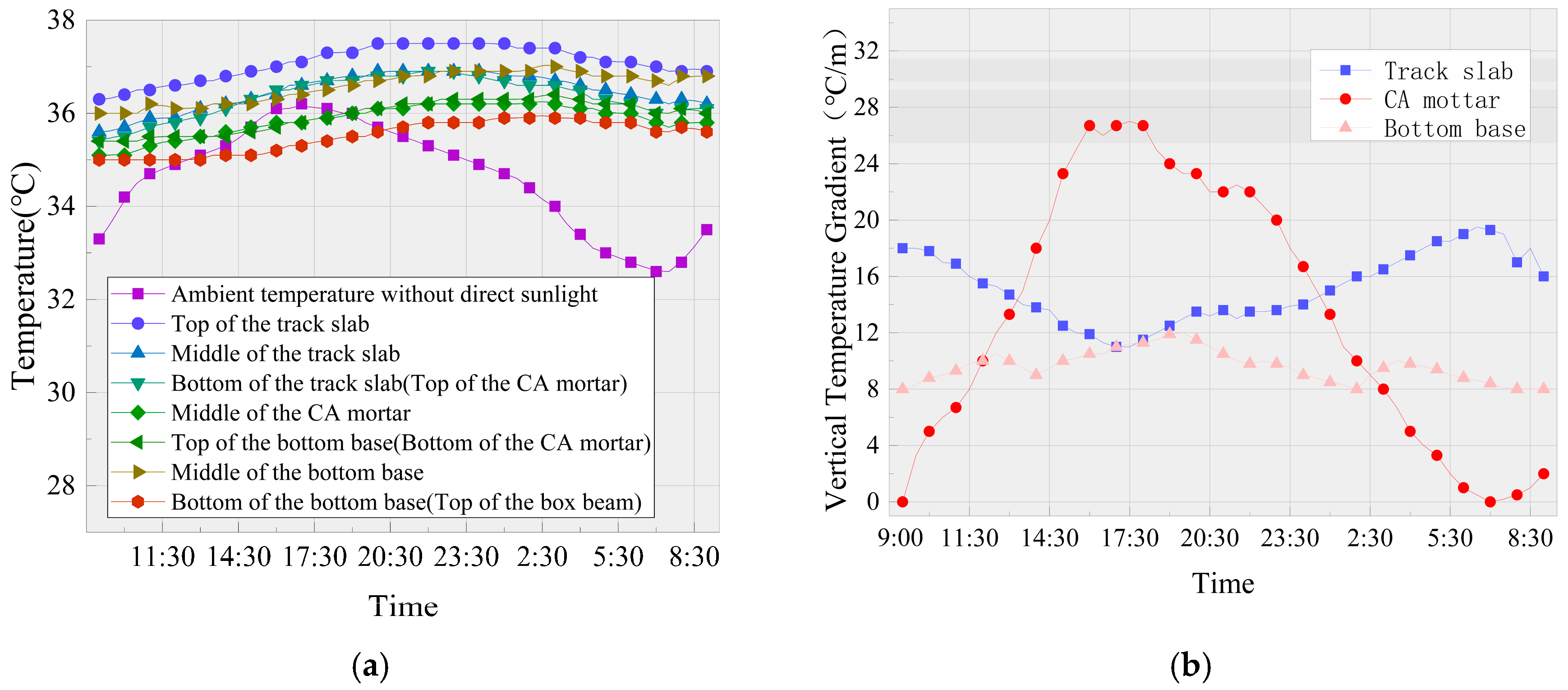
The temperature of each structural layer of the track system changes with the change in the ambient temperature, showing a sine curve periodic change rule of increasing first and then decreasing; because of the poor thermal conductivity of the material, the temperature change in the track system lags behind the change in the ambient temperature, and the lag feature is more obvious with the increase in the depth from the top of the track slab.
(2)
During the 24-h test, the strain of each structural layer shows a sine curve periodic change of increasing first and then decreasing; because the strain time history law of the track system structure is affected by the hysteresis of the temperature change, the strain change of each structural layer has a certain lag along with the vertical depth. Due to the different temperatures at the beginning and end of the test, at 9:00 the next day, the strain of the track system structure at each location did not return to the initial state; the shear slots have a certain constraint on the track system structure, and the strain near the shear slot side of the structure is smaller than that on the other side.
(3)
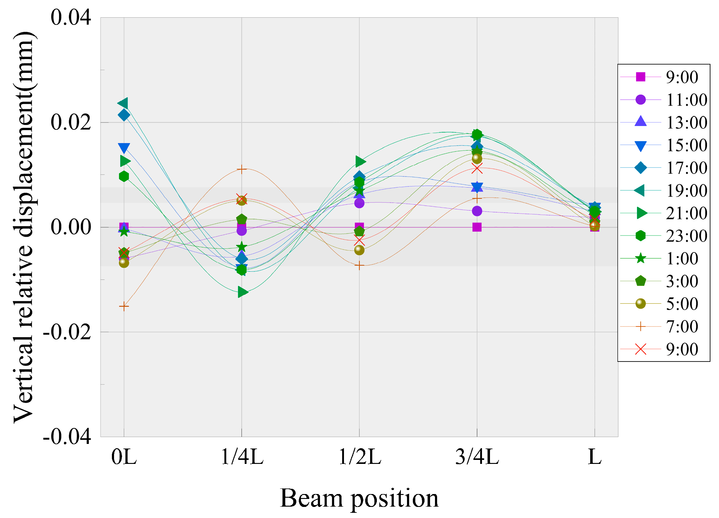
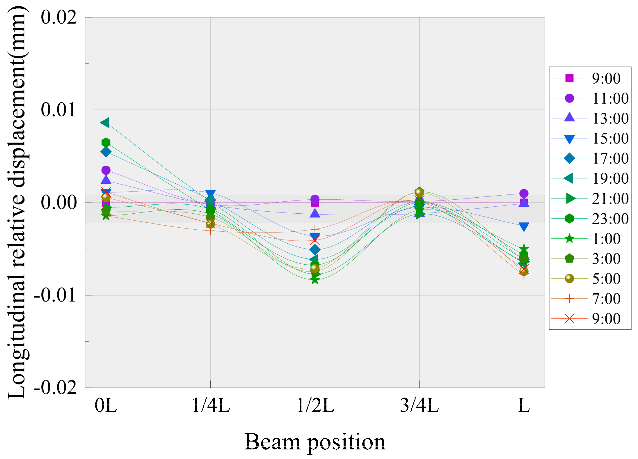
Under the cyclic action of the temperature change in a single-day, the longitudinal and vertical relative displacements of the track system layers work together under the constraint of the beams, shear slots and track itself to realize the deformation of the track system; during the period from 17:00 to 23:00, the relative displacements of the whole layer are relatively small; due to the influence of the shear slots, the deformation of the track system and the relative displacement between the layers on the side near the shear slots (at section 0 L) are mostly realized by the track slab and CA mortar layer, while the relative displacement between the base plate and the beam body on the other side (at section L) is relatively large; the most unfavorable position is at section 1/4 L, where there is a peak value of the relative displacement between the layers, so this position should be considered.
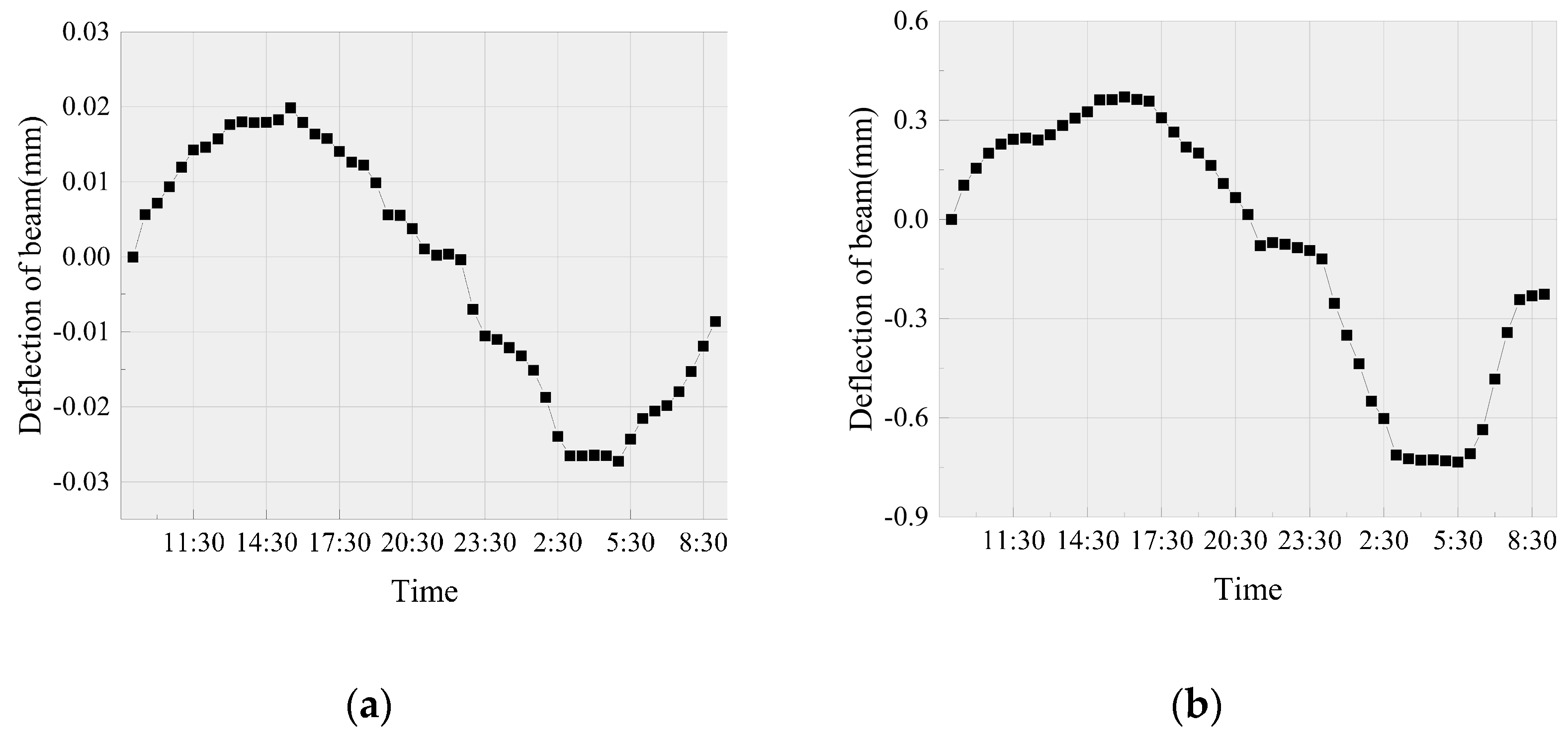
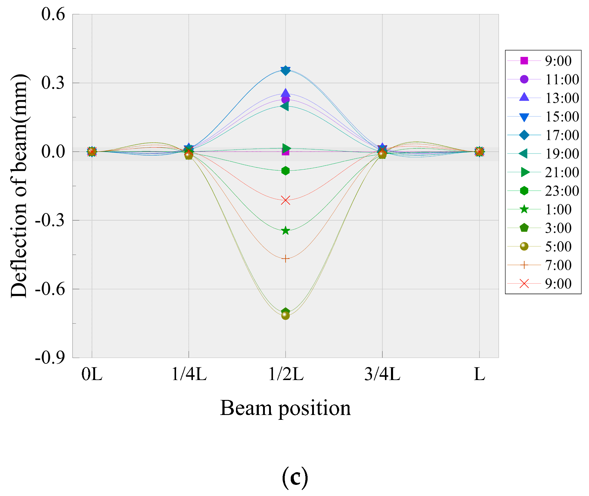
(4)
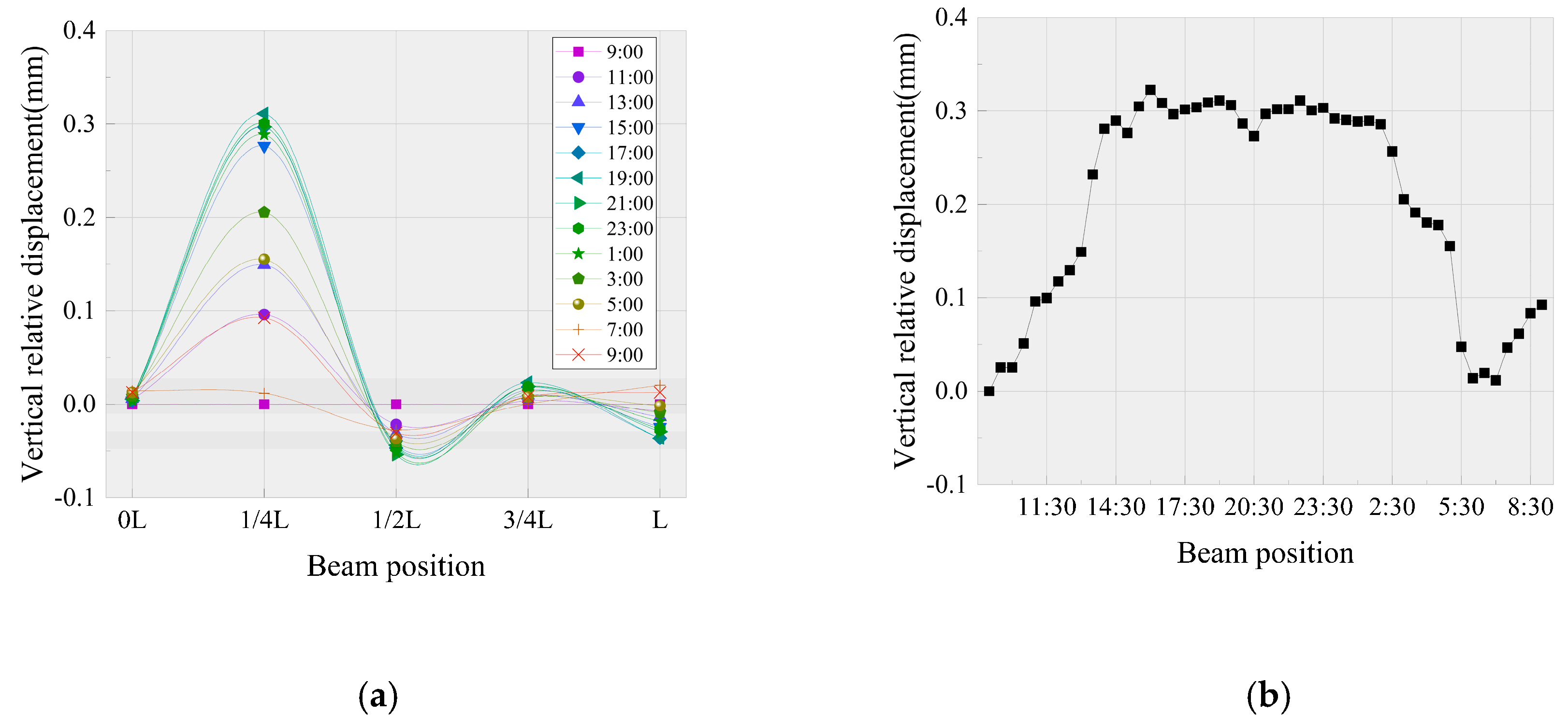
Under the condition of high temperatures and no direct sunlight in summer, the deflection of the middle span of the CRTS II ballastless track simply supported box girder bridge structure system is the largest; the upper arch of the middle span section reaches 0.4 mm in the heating stage, and the lower deflection of the middle span section reaches 0.7 mm in the cooling stage. The deflection of the whole bridge in the cooling stage is slightly larger than that in the heating stage, so the cooling ratio has a significant impact on the deflection of the bridge.
(5)
For the existing ballastless track-bridge system, the structural displacement and deformation will lead to the change of ballastless track support state, which will lead to the change of track structure stress and force transmission mode and easily lead to track structure diseases. Therefore, it is suggested that the maintenance personnel should strengthen the inspection of the joints between the structural layers during the continuous high-temperature period, especially the inspection at 1/4 L, so as to grasp the best opportunity for maintenance and repair.

Author Contributions

Conceptualization, L.Z. (Lingyu Zhou), Y.Y., L.Z. (Lei Zhao), A.D.G.M., L.Z. (Lifan Zou) and W.H.; methodology, L.Z. (Lingyu Zhou), Y.Y., L.Z. (Lei Zhao), A.D.G.M., L.Z. (Lifan Zou) and W.H.; validation, L.Z. (Lingyu Zhou), Y.Y., L.Z. (Lei Zhao), A.D.G.M., L.Z. (Lifan Zou) and W.H.; formal analysis, L.Z. (Lingyu Zhou), Y.Y., L.Z. (Lei Zhao), A.D.G.M., L.Z. (Lifan Zou) and W.H.; investigation, L.Z. (Lingyu Zhou), Y.Y., L.Z. (Lei Zhao), A.D.G.M., L.Z. (Lifan Zou) and W.H.; resources, L.Z. (Lingyu Zhou), Y.Y., L.Z. (Lei Zhao), A.D.G.M., L.Z. (Lifan Zou) and W.H.; data curation, L.Z. (Lingyu Zhou), Y.Y., L.Z. (Lei Zhao), A.D.G.M., L.Z. (Lifan Zou) and W.H.; writing—original draft preparation, L.Z. (Lingyu Zhou), Y.Y., L.Z. (Lei Zhao), A.D.G.M., L.Z. (Lifan Zou) and W.H.; writing—review and editing, L.Z. (Lingyu Zhou), Y.Y., L.Z. (Lei Zhao), A.D.G.M., L.Z. (Lifan Zou) and W.H.; visualization, L.Z. (Lingyu Zhou), Y.Y., L.Z. (Lei Zhao), A.D.G.M., L.Z. (Lifan Zou) and W.H.; supervision, L.Z. (Lingyu Zhou), Y.Y., L.Z. (Lei Zhao), A.D.G.M., L.Z. (Lifan Zou) and W.H.; project administration, L.Z. (Lingyu Zhou), Y.Y., L.Z. (Lei Zhao), A.D.G.M., L.Z. (Lifan Zou) and W.H.; funding acquisition, L.Z. (Lingyu Zhou), Y.Y., L.Z. (Lei Zhao), A.D.G.M., L.Z. (Lifan Zou) and W.H. All authors have read and agreed to the published version of the manuscript.

Funding

This research was funded by the National Natural Science Foundation of China, grant number 51578546, the High Speed Railway Unit Foundation of China, grant numbers U1434204 and U1934217, and the Fundamental Research Funds for the Central Universities of Central South University, grant number 2020zzts157.

Acknowledgments

Special thanks are extended to the reviewers for their valuable suggestions. The authors would like to thank the National Engineering Laboratory of High-Speed Railway Construction Technology of China, the staff of the laboratory for their help in the smooth development of the experiment and the reviewers for their hard work.

Conflicts of Interest

The authors declare no conflict of interest.

References

  1. Zhou, L.Y.; Yang, L.Q.; Shan, Z.; Peng, X.S.; Akim, D.M. Investigation of the fatigue behaviour of a ballastless slab track-bridge structure system under train load. Appl. Sci. 2019, 9, 3625. [Google Scholar] [CrossRef] [Green Version]
  2. Zhao, L.; Zhou, L.Y.; Zhang, G.C. Experimental Study of the Temperature Distribution in CRTS-II Ballastless Tracks on a High-Speed Railway Bridge. Appl. Sci. 2020, 10, 1980. [Google Scholar] [CrossRef] [Green Version]
  3. Guo, W.; Hu, Y.; Gou, H.Y. Simplified seismic model of CRTS II ballastless track structure on high-speed railway bridges in China. Eng. Struct. 2020, 211, 110453. [Google Scholar] [CrossRef]
  4. Xiao, H.; Zhang, Y.R.; Li, Q.H. Analysis of the initiation and propagation of fatigue cracks in the CRTS II slab track inter-layer using FE-SAFE and XFEM. Proc. Inst. Mech. Eng. Part F J. Rail Rapid Transit. 2019, 233, 678–690. [Google Scholar] [CrossRef]
  5. Zhang, M.-N.; Hu, Z.-P.; Wu, Y.-B. Influence of Pier Temperature Increase on Jointless Track of Large-Span Bridge with High-Pier. Railw. Stand. Des. 2014, 58, 32–35. [Google Scholar]
  6. Chen, Z.; Xiao, J.L.; Liu, X.Y. Deformation behavior of slab warping for longitudinal continuous rigid slab under temperature effect. Adv. Struct. Eng. 2019, 22, 2823–2836. [Google Scholar] [CrossRef]
  7. Westgate, R.; Koo, K.Y.; Brownjohn, J. Effect of Solar Radiation on Suspension Bridge Performance. J. Bridge Eng. 2015, 20, 04014077. [Google Scholar] [CrossRef] [Green Version]
  8. Wang, J.; Zhou, Y.; Wu, T. Performance of Cement Asphalt Mortar in Ballastless Slab Track over High-Speed Railway under Extreme Climate Conditions. Int. J. Geomech. 2019, 19, 04019037. [Google Scholar] [CrossRef]
  9. Gonzales, I.; Ulker-Kaustell, M.; Karoumi, R. Seasonal effects on the stiffness properties of a ballasted railway bridge. Eng. Struct. 2013, 57, 63–72. [Google Scholar] [CrossRef]
  10. Tong, M.; Tham, L.G.; Au, F.T.K. Numerical modelling for temperature distribution in steel bridges. Comput. Struct. 2001, 79, 583–593. [Google Scholar] [CrossRef]
  11. Semendary, A.A.; Steinberg, E.P.; Walsh, K.K. Effects of Temperature Distributions on Thermally Induced Behavior of UHPC Shear Key Connections of an Adjacent Precast Prestressed Concrete Box Beam Bridge. J. Bridge Eng. 2019, 24, 04018115. [Google Scholar] [CrossRef]
  12. Cai, X.P.; Luo, B.C.; Zhong, Y.L. Arching mechanism of the slab joints in CRTSII slab track under high temperature conditions. Eng. Fail. Anal. 2019, 98, 95–108. [Google Scholar] [CrossRef]
  13. Ou, Z.; Sun, L. Value of Temperature Loads on Probability Demand for Ballastless Track Slab Ⅱ: Thermal Gradient Actions. J. China Railw. Soc. 2018, 40, 80–86. [Google Scholar]
  14. Stancik, V.; Ryjacek, P.; Vokac, M. Thermal and load rate-dependent interaction between embedded rail system and bridge. Proc. Soc. Mech. Eng. 2019, 233, 326–336. [Google Scholar] [CrossRef]
  15. Jiang, H.L.; Zhang, J.W.; Zhou, F. Optimization of PCM coating and its influence on the temperature field of CRTSII ballastless track slab. Constr. Build. Mater. 2020, 236, 117498. [Google Scholar] [CrossRef]
  16. Mirambell, E.; Aguado, A. Temperature and Stress Distributions in Concrete Box Girder Bridges. J. Struct. Eng. 1990, 116, 2388–2409. [Google Scholar] [CrossRef]
  17. Dai, G.; Su, H.; Liu, W. Temperature Distribution of Longitudinally Connected Slab Ballastless Track on Bridge in Summer. J. Cent. South Univ. Sci. Technol. 2017, 4, 1073–1080. [Google Scholar]
  18. Liu, W.S.; Dai, G.L.; Rao, S.C. Numerical calculation on solar temperature field of a cable-stayed bridge with U-shaped section on high-speed railway. J. Cent. South Univ. 2014, 21, 3345–3352. [Google Scholar] [CrossRef]
  19. Dai, G.-L.; Su, H.-T.; Yan, B. Experimental Study on the Vertical Temperature Gradient of Longitudinally Connected Slab Ballastless Track on Bridge in Autumn. J. Hunan Univ. Nat. Sci. Ed. 2015, 42, 94–99. [Google Scholar]
  20. Liu, F.; Zeng, Z.; Wu, B. Study on Temperature Field of Continuous Ballastless Track for High-Speed Railway. J. Railw. Soc. 2016, 12, 87–93. [Google Scholar]
  21. Zhong, Y.L.; Gao, L.; Zhang, Y.R. Effect of daily changing temperature on the curling behavior and interface stress of slab track in construction stage. Constr. Build. Mater. 2018, 185, 638–647. [Google Scholar] [CrossRef]
  22. Wang, S.; Sun, L.; Li, Q. Temperature Measurement and Temperature Stress Analysis of Ballastless Track Slab. J. Railw. Soc. 2009, 2, 52–55. [Google Scholar]
  23. Salcher, P.; Pradlwarter, H.; Adam, C. Reliability assessment of railway bridges subjected to high-speed trains considering the effects of seasonal temperature changes. Eng. Struct. 2016, 126, 712–724. [Google Scholar] [CrossRef]
  24. Zhu, J.S.; Guo, X.D.; Meng, Q.L. Analysis of fine temperature field for bridge-track system of high-speed railway. China Railw. Sci. 2019, 40, 36–45. [Google Scholar]
  25. Cardona, M.; Kremer, R.K. Temperature dependence of the electronic gaps of semiconductors. Thin Solid Films 2014, 571, 680–683. [Google Scholar] [CrossRef]
Figure 1. Specimen cross-section (Unit: mm).
Applsci 10 05504 g001
Figure 2. Three-span simply supported beam. (a) Facade design drawing of the model (Unit: mm); (b) scaled model diagram (Test section).
Applsci 10 05504 g002
Figure 3. The layout of the temperature gauges (Unit: mm).
Applsci 10 05504 g003
Figure 4. The layout of the fiber Bragg grating (FBG) strain sensors (Unit: mm).
Applsci 10 05504 g004
Figure 5. The layout of the linear displacement gauge (Unit: mm). (a) Vertical LVDT displacement meter; (b) Longitudinal LVDT displacement meter.
Applsci 10 05504 g005
Figure 6. Temperature time history curve. (a) Temperature time history curve of the whole test process; (b) temperature gradient time history curve of the inter layer.
Applsci 10 05504 g006
Figure 7. Strain-time history curve for the track system. (a) 0 L; (b) 1/2 L; (c) L.
Applsci 10 05504 g007
Figure 8. Vertical relative displacement between the base plate and beam body. (a) Vertical relative displacement; (b) vertical relative displacement time history curve at 1/4 L.
Applsci 10 05504 g008
Figure 9. The displacement between the track slab and base slab.
Applsci 10 05504 g009
Figure 10. The displacement between the track slab and CA mortar layer.
Applsci 10 05504 g010
Figure 11. Displacement between the base plate and beam body.
Applsci 10 05504 g011
Figure 12. Displacement between the track slab and base plate.
Applsci 10 05504 g012
Figure 13. Longitudinal relative displacement between the CA mortar layer and base plate.
Applsci 10 05504 g013
Figure 14. Deflection curve of the beam body. (a) Quarter point; (b) midspan; (c) deflection curve.
Applsci 10 05504 g014aApplsci 10 05504 g014b

