Article

Internal Force Analysis of Buried-boring Piles in the Yuanzishan Landslide

1
School of Civil Engineering and Architecture of Henan University, Kaifeng 475004, China
2
College of Science, Engineering of Flinders University, Adelaide 5042, Australia
*
Author to whom correspondence should be addressed.
Appl. Sci. 2020, 10(16), 5416; https://doi.org/10.3390/app10165416
Submission received: 9 June 2020 / Revised: 30 July 2020 / Accepted: 3 August 2020 / Published: 5 August 2020
(This article belongs to the Special Issue Advances in Geotechnical Engineering)

Abstract

:
The Yuanzishan landslide is an unstable slope in Langzhong County, located in northeast Sichuan province, China. The Guangyuan-Nanchong expressway passes through the front edge of the unstable slope, and subgrade excavation has resulted in slope deformation, which threatens the safety of the highway construction. Emergency landslide control requires reduction of the slope disturbance. This study aims to investigate the use of buried-boring piles as a potential method for emergency landslide control. A simplified calculation method was used for the design of the buried-boring piles, according to the limit equilibrium of the soil and the elastic foundation coefficient method. The measured internal force changes of the pile were compared, in order to determine the distribution coefficients of the driving force. A relationship between the driving force of the shared pile ratio and the buried depth ratios was then established. Furthermore, a variety of factors affecting the internal forces of the buried-boring pile and the lateral reaction of the soil were also studied. The results revealed that (1) there was a quadratic relationship between the driving force of the pile-shared ratio and the sliding depth ratios; (2) the maximum bending moment of the pile increased with an increase in the sliding depth ratio of the pile, following a power law relationship; (3) increasing the buried depth of the pile head reduced the influence of the pile diameter on the maximum internal forces; (4) increasing the pile diameter decreased the maximum lateral reaction of the soil. The buried-boring piles can be used in similarly unstable regions for emergency control of deforming slopes.

1. Introduction

During the construction of the Guangyuan–Nanchong Expressway, in the northeast Sichuan province of China, many embankment slopes were formed by excavation and dumping. Several of the excavated slopes are at risk of sliding along the original surface of the Guangyuan–Nanchong Expressway. Emergency control measures are needed to reduce disturbance to the slope [1]. Buried-boring piles were machined into holes and poured into piles, whose heads were buried under the ground surface to a certain depth. Buried-boring piles result in less disturbance to the slope and are used for emergency control of unstable slopes.
Many scholars have investigated the mechanism of the pile–soil interaction under lateral loads. Motta [2] and Broms [3,4] studied the horizontal deflection of laterally loaded piles in an elastoplastic medium and proposed formulae in order to calculate the ultimate bearing capacity of round piles in cohesive and cohesionless soils. Hsiung et al. [5] investigated the maximum deflection and moment for laterally loaded piles under combined loads. Basu et al. [6] developed a new method of analyzing laterally loaded piles embedded in multi-layered soil using energy principles. Xu et al. [7,8] proposed a modified strain wedge model for the nonlinear analysis of laterally loaded single piles in sandy soils and determined the effect of low-plasticity fines on the lateral response of piles in sand. The displacement of a concrete bored pile under a lateral load is nonlinear [9,10,11]. The ultimate contact pressure behind the pile is different between the stiff shaft and the flexible shaft, depending on soil cohesion. When contact pressure fills the contact surface, the relative displacement between the moving soil and the moving drilled shaft ranged from 3% to 15% of the shaft diameter [12,13,14,15]. The pile head displacement and the pile bending moment increased significantly with the increasing of the lateral load in the model experiments [16,17,18,19,20]. If a single pile is combined into a group pile, the pile head is connected by a connecting beam, limiting the pile displacement [20,21,22]. A single bored pile is limited by the cross-sectional size and cannot bear a larger lateral load.
Utilization of a buried anti-slide pile reduces the pile length above the slip surface and jointly bears the driving force of the slope deformation with the soil [23,24], a technique that is widely used in landslide prevention. Zeng [25] used the limit method to calculate the buried depth of a buried anti-sliding pile. Hui [26] and Zhao et al. [27] used a numerical model to analyze the internal force of buried anti-sliding piles and pile–soil interaction during a landslide. Xiong [28] used an experiment to study the ratio of the pushing force of a landslide acting on a buried pile to the residual driving force of the landslide and the pile–soil interaction under varying buried depths.
The previous studies, mentioned above, have investigated the mechanism of the bored pile–soil interaction under lateral loads and have also studied the influence of the buried depth on slope stability. However, even though the bored pile diameter is an important structural design parameter, the influence of pile diameter change on the internal force of the buried pile has rarely been studied. There is also limited research investigating the influence of the buried depth of the pile head on the lateral reaction force of the soil below the slip surface, although this is an important criterion for the success or failure of the buried pile. Hence, further research is needed on the effect of pile diameter changes on the internal force of buried-boring piles and the maximum lateral reaction force of the soil at different buried-boring pile head depths. This study proposes the use of buried-boring piles for emergency control of an unstable slope, specifically applied to the case of the Yanzishan landslide in Langzhong county, located in the northeast of the Sichuan province of China. The Yuanzishan landslide is typical in that it was caused by roadbed excavation; therefore, its emergency treatment technology has a wide application value. We suggest a simplified calculation method for the design of buried-boring piles that considers the limit equilibrium of the soil and utilizes the elastic foundation coefficient method. We compared the measured internal force changes of the pile, determined the distribution coefficient of the driving force, and established the relationship between the driving force of the shared pile ratio and the buried depth ratio. Furthermore, the influence of the pile diameter and the buried depth of the pile head on the internal force of the pile, as well as the lateral reaction of the soil, were also studied.

2. Methodology and Validation

2.1. Simplified Calculations of Buried-Boring Piles during a Landslide

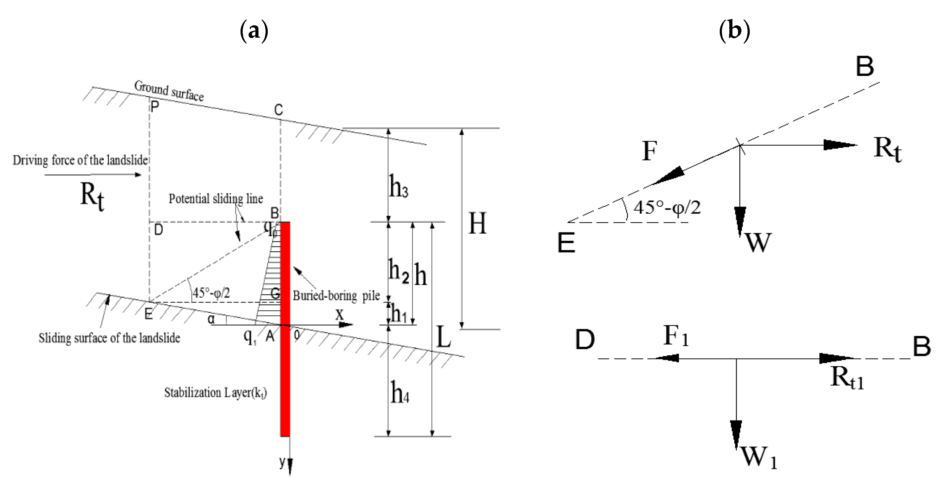
2.1.1. Basic Assumptions

Three assumptions were made in order to simplify the buried-boring pile calculations:
(1)
it was assumed that the driving force of the landslide was transmitted to the foundation of the bored pile, with the friction force at the top of the pile and the reaction force at the pile bottom assumed to be negligible;
(2)
the bored pile was assumed to be in a fragile state, such that the displacement of the soil in front of the pile was equal to the pile displacement above the slip surface. The pile was simplified as a cantilever beam; thus, the resistance force of the soil in front of the pile is negligible;
(3)
the potential fracture surface in the slope body was assumed to be the Coulomb fracture surface [25], such that the shear strength of the soil above the slip surface was constant at φ and the slope, a, of the slip surface at the pile location was parallel to the ground slope. By making these assumptions, the thrust distribution was simplified to a trapezoidal load.
According to the above assumptions, the stress model of a buried-boring pile is shown in Figure 1. The stress calculations involved three steps: (1) determination of the pile length above the slip surface; (2) calculation of the internal force of the pile above the slip surface; and (3) calculation of the internal force of the pile below the slip surface.

2.1.2. Determination of the Pile Length above the Slip Surface

The buried-boring pile was integrated with the soil on the top of the pile in order to bear the driving force of the landslide. The driving force of the landslide above the pile top is balanced by the strength of the soil. The soil behind the pile could potentially slide along the passive earth pressure failure surface, EB, under the driving force of the landslide, or it could slide along the horizontal plane, DB, (Figure 1a). Two basic balance equations were determined to give the pile length above the slip surface [25].
When the slope fails along the EB plane behind the pile, the forces present are the driving force of the landslide Rt, the soil weight (the surface EBCP) W, and the friction force F on the EB surface (Figure 1b). These three forces establish a balance equation along the EB surface, and the safety factor K is equal to the anti-sliding force divided by the sliding force:
K = W s i n ( 45 ° φ 2 ) + F R t c o s ( 45 ° φ 2 )
where Rt is the landslide driving force; K is the design safety factor [23], such that when K = 1, the slope is in limit equilibrium; and W is the soil weight at the surface EBCP (Figure 1), which was calculated by the gravity density multiplying the area of the surface EBCP:
W = γ H h 2 c o t ( 45 ° φ 2 ) b 0.5 γ h 2 2 c o t ( 45 ° φ 2 ) [ c o t ( 45 ° φ 2 ) t a n α + 1 ] b
where γ is the soil weight density; φ   is the soil friction angle; h2 is the pile length (BG) above the horizontal plane; b is the width of the soil acting on the pile; and a is the slope of the slip surface.
The friction force F on the EB surface is calculated by the friction coefficient (tan   φ ) multiplying the vertical component force on the EB surface, which is generated by the landslide thrust (Rt) and the weight of the soil at the surface EBCP (W):
F = t a n ( φ ) [ W c o s ( 45 ° φ 2 ) + R t s i n ( 45 ° φ 2 ) ]
When the slope fails along the EB plane behind the pile, the forces present are the driving force of the landslide above the pile top (Rt1), the soil weight ( the surface DBCP) W1, and the friction force F1 on the DB surface (Figure 1b). These three forces establish a balance equation along the DB surface, and the safety factor K is equal to the anti-sliding force divided by the sliding force:
K = F 1 R t 1
where F1 is the friction force on the DB surface, which is calculated by the friction coefficient (tan   φ ) multiplying the weight of the soil at the surface DBCP (W1) on the DB surface:
F 1 = t a n ( φ ) W 1
where   W 1 is the soil weight at the surface DBCP (Figure 1a), calculated by the gravity density multiplying the area of the surface DBCP:
W 1 = γ [ h 3 h 2 c o t ( 45 ° φ 2 ) + 0.5 [ h 2 c o t ( 45 ° φ 2 ) ] 2 t a n α ] b
where h2 denotes the pile length (BG) above the horizontal plane (Figure 1a); and h3 is the depth of the pile head below the ground surface, which was calculated via:
h 3 = H h 2 h 2 t a n α t a n ( 45 ° φ 2 )    
The driving force of the landslide above the pile top (Rt1) can be calculated according to Equation (8):
R t 1 = R t H h 3
Solving Equations (1) and (4) for the pile length above the horizontal plane h2 and h2, respectively, and taking the maximum value as h2max, allowed the bored pile length h above the slip surface to be calculated according to Equation (9):
h = t a n α * h 2 m a x t a n ( 45 ° φ 2 ) + h 2 m a x

2.1.3. Internal Force the of Bored Pile above the Slip Surface

The driving force of the landslide was unevenly distributed to the bored pile between the pile head and the slip surface, according to Figure 1a. In order to solve the strength of the driving force behind the pile, the driving force of the landslide (Rt) is distributed on the plane of the pile rear according to the trapezoidal load strength, and the ratio of the driving force strength distribution between the ground and the sliding surface is m, so that the strength of the driving force at any point from the ground to the sliding surface can be obtained. The strength of the driving force on the head of the buried pile q0 was calculated according to Equation (10):
q 0 = 2 R t m H ( 1 + m ) + 2 R t ( 1 m ) H 2 ( 1 + m ) h 3
where m is the distribution coefficient of the driving force, which was determined by the soil properties [29]; H is the distance from the slip surface to the ground at the pile location.
The strength of the driving force at the slip surface q1 was calculated according to:
q 1 = 2 R t H ( 1 + m )
The bending moment My and the shear force Qy, along with the pile above the slip surface, under the action of the driving force, were calculated via the following formulae [30]:
Q y = q 0 ( h | y | ) + ( q 1 q 0 ) ( h | y | ) 2 2 h ( y < 0 ,   | y |   h )
M y = q 0 ( h | y | ) 2 2 + ( q 1 q 0 ) ( h | y | ) 3 6 h ( y < 0 ,   | y |   h )
where y is the distance from the slip surface.

2.1.4. Internal Force of the Bored Pile below the Slip Surface

The lateral load acting on the buried-boring pile below the slip surface was expressed using the following equation [31]:
E I d 4 x d y 4 + x k 1 B P = 0       ( 0 < y h 4 )
where k1 is the modulus of the subgrade reaction of the bedrock to lateral force for the anti-slide pile, which is determined by the compressive strength of the rock [23]; E is the Young modulus of the pile, and I is the moment of inertia of the pile, where I=π*D4/64 and D is the diameter of the buried-boring pile; Bp is the calculation width of the pile, which was calculated using the following formula [32]:
B P = 0.9 × ( 1.5 D + 0.5 )
The following expressions were obtained by solving the previous equations [33]:
M y = 4 x 0 β 2 E I φ 3 4 θ 0 β E I φ 4 + M 0 φ 1 + Q 0 β φ 2 ;
Q y = 4 x 0 β 3 E I φ 2 4 θ 0 β 2 E I φ 3 4 M 0 β φ 4 + Q 0 φ 1 ;
θ y = β ( 4 x 0 φ 4 + θ 0 β φ 1 + M 0 β 2 E I φ 2 + Q 0 β 3 E I φ 3 ) ;
x y = x 0 φ 1 + θ 0 β φ 2 + M 0 β 2 E I φ 3 + Q 0 β 3 E I φ 4 ;
where Qy, My, xy, and θy are the shear force, bending moment, horizontal displacement, and rotation angle for the pile below the slip surface with changing depth, respectively; Q0, M0, x0 and θ0 are the shear force, bending moment, horizontal displacement, and rotation angle for the pile located at the slip surface, respectively; φ 1 , φ 2 , φ 3 , and φ 4 are influence moduli that were calculated using the following equations [33,34]:
φ 1 = cos ( β y ) cosh ( β y )
φ 2 = 1 2 [ sin ( β y ) cos h ( β y ) + cos ( β y ) sin h ( β y ) ]
φ 3 = sin ( β y ) sin h ( β y )
φ 4 = 1 4 [ sin ( β y ) cos h ( β y ) cos ( β y ) sin h ( β y ) ]
In Equations (16)−(19), y is the calculated depth of the pile below the slip surface and β is the coefficient of deformation, which was calculated by the following formula [33]:
β = ( k 1 B p 4 E I ) 1 4
Other external forces acting on the pile head were negligible in the calculations [33]. The solution of Equations (16)–(19) was dependent on the values of M0, Q0, x0 and θ0. Lateral load conditions can be used to determine M0 and Q0, whereas the lower pile boundary condition can be used to determine x0 and θ0 [29]. By substituting calculated values of M0, Q0, x0 and θ0 into Equations (16)–(19), My, Qy, xy, and θy could be obtained at any depth of the buried-boring pile below the slip surface.

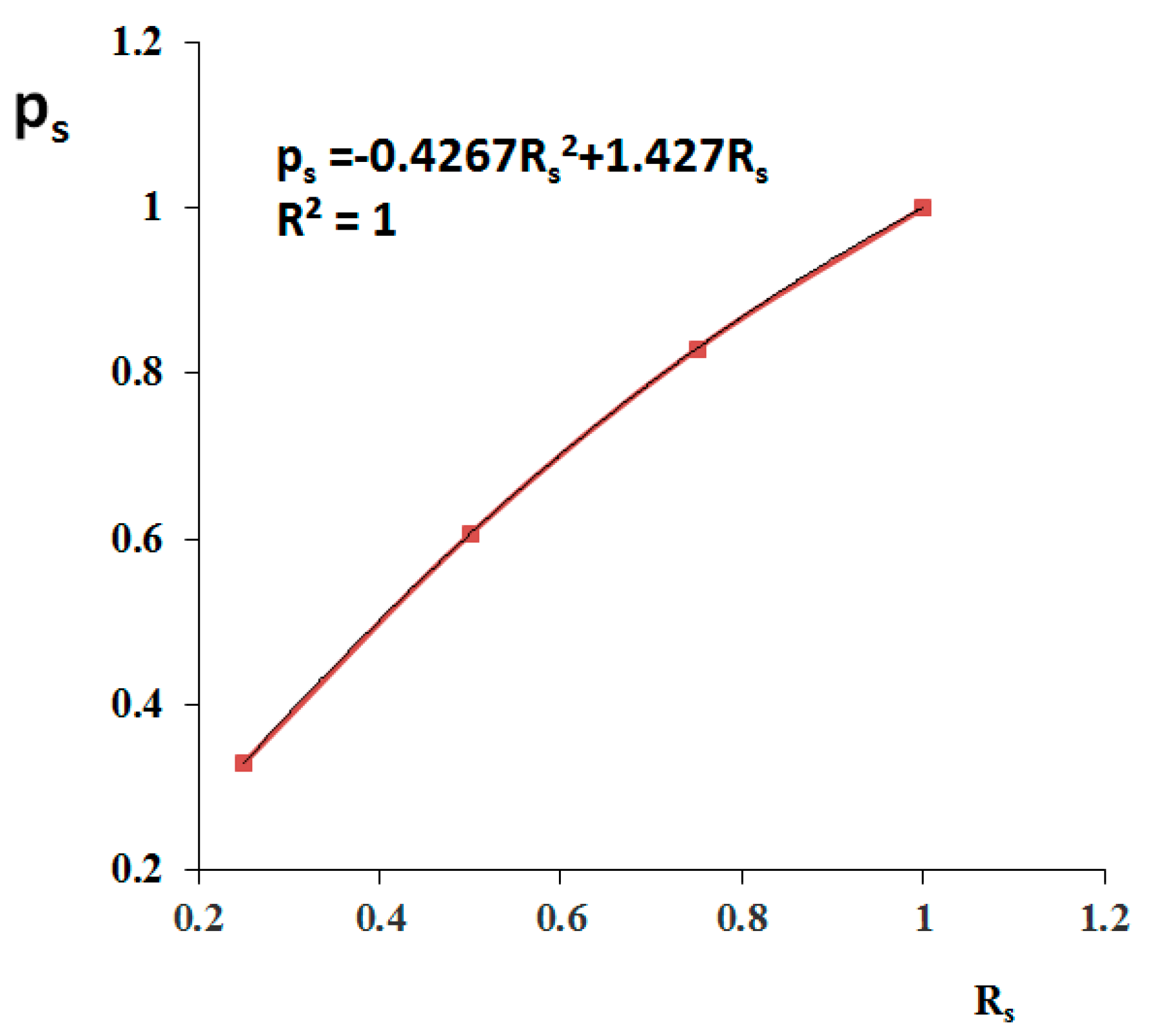
2.2. Validation of the Calculation Method and Determination of the Driving Force Distribution Coefficient

Lirer [35] conducted a long-term monitoring study on a circular anti-slide pile with a diameter of 0.4 m on the Masseria Marino landslide, Italy, and determined the change of bending moment and shearing force of the pile during the landslide failure. The relevant geotechnical parameters are listed in Table 1.
The ratio of the driving force acting on the pile head to the driving force acting at the slip surface is defined as the distribution coefficient of the driving force, m, which has an important influence on the internal force of the pile [36]. In order to determine the distribution coefficient of the driving force after a landslide has occurred, the internal force of the bored pile can be calculated using the method defined in this paper. The driving force of the landslide, Rt, used in the calculation was 100 kN/m; the modulus of subgrade reaction of the soil, k1, was 30,000 kPa/m; the diameter of the pile, D, was 0.4 m; the total length of the pile, L, was 10 m; the length of the pile above the slip surface, h, was 5 m; and the elastic modulus of the pile, E, was 3.0 × 10⁷ kPa. For distribution coefficients of the driving force of 0, 0.4, and 1, according to Equations (12) and (13) and Equations (16) and (17), the internal force of the bored pile was calculated and compared with Lirer’s results (Figure 2). The bending moment and shear force below the slip surface increased as the distribution coefficient of thrust increased (Figure 2). The shear force and bending moment of the bored pile calculated by our method exhibited a similar trend to the monitoring results, but the position of the maximum bending moment and the shear force of the pile below the slip surface were slightly higher. This is potentially due to a difference in the soil resistance in front of the pile, which may have affected internal forces. According to the calculation results of shear force and bending moment, when the distribution coefficient of the driving force was 0.4, our results closely matched the monitoring results of Lirer.

3. Application of Buried-Boring Piles in the Yanzishan Landslide

3.1. Geological Background of the Yanzishan Landslide

The Yanzishan landslide is located in Jiangnan Town, Langzhong City, Sichuan Province, China (31°34′05.0″ N, 105°56′20.0″ E). The slope elevation is approximately 480 m. The slope profile is divided into two levels of gentle platforms (Figure 3a). The elevation of the central platform is approximately 410 m, with an average gradient of 11°. The lower platform has an elevation of approximately 395 m, a width of approximately 70 m, and an average gradient of 9°. The Guangyuan-Nanchong Expressway passes through the front edge of the lower platform, and subgrade excavation during construction of the highway resulted in slope deformation (Figure 3b), which is a current threat to the safety of the highway.
The slope body is mainly composed of quaternary slope deposits, with silty clay above the slip surface and muddy siltstone below the slip surface. The relevant geotechnical engineering parameters are shown in Table 2.
The slip surface is buried at a depth of 10 m. The unbalanced thrust coefficient method was used to calculate the residual driving force of the landslide [31]. The residual driving force of the cross-section from A to A′ of the Yanzishan landslide (Figure 4) was 300 kN/m. Emergency control of the landslide is needed to reduce slope deformation. Bored piles are proposed as an emergency control method.

3.2. Application of Buried-Boring Piles to the Yanzishan Landslide

The cross-section from A to A′ of the Yanzishan landslide was selected in order to design the buried-boring piles in the calculation. The spacing between the piles was 1 m. The diameter of the pile, D, was 0.5 m. The moment of inertia of the buried-boring pile, I, was 3.066 × 10⁻² m4. The Young modulus, E, of the buried-boring pile was 30 GPa. The driving force of the landslide, p, was 300 kN/m. The angle of the slip surface, a, was 5°. For the value of c, we can use equivalent soil strength to transform the integrated internal friction angle [37]. If the value of c is not large, the friction angle ( φ ) of the soil can be directly used, which is more conducive to engineering safety. A soil safety factor of 1.3 was used, along with a driving force distribution coefficient of 0.4, when the slope slid along the EB surface (Figure 1). The minimum pile length above the slip surface was 0.86 m, based on Equations (1) and (9). When the slope body slid along the DB surface (Figure 1), the minimum pile length above the slip surface was calculated to be 2.12 m, based on Equations (4) and (9). Therefore, in the design of the bored piles for emergency landslide control, the pile length above the slip surface should be at least 2.5 m.
In order to study the ratio of the pushing force of the landslide acting on the buried pile to the residual driving force of the landslide, a buried depth ratio, Rs [28], was defined as the pile length above the slip surface, h, divided by the depth of the slip surface (H, Figure 1). The ratio of the driving force across the shared piles, Ps, was defined as the driving force of the landslide acting on the piles divided by the driving force of the landslide at a specific pile location. If the pile length above the slip surface was 2.5 m and the depth of the slip surface was 10 m in engineering design, Rs = 25%. Using Equations (10) and (11), the driving force at the top of the pile, q0, was 36.43 kPa, and the driving force strength at the slip surface, q1, was 42.86 kPa. In this case, the driving force of the landslide acting across the piles was calculated to be 99.1 kN, such that Ps = 33%. For varying h values of 5, 7.5, and 10 m, different Rs values and corresponding Ps values were calculated (Figure 5).
The ratio of the driving force across the shared piles increased quadratically as the buried depth ratio increased. When Rs = 50%, Ps = 60.7% (Figure 5). Xiong [28] used driving force experiments to study the force distribution law of buried piles at large depths and measured that, for Rs = 54%, the driving force of the landslide acting on the bored pile accounted for 59% of the total driving force of the landslide, which is consistent with our calculations (60.7%).

4. Influence of Parameter Changes on the Internal Force of the Buried-Boring Pile

4.1. Influence of Depth of Buried Length above Slip Surface on the Internal Force of the Pile

The internal force of the bored pile is an important parameter for anti-slide pile structure design [23]. In order to study how the depth of the buried-boring pile head from the surface influenced the internal force of the buried-boring pile, the pile head depths were varied at 0, 2.5, 5, and 7.5 m, with corresponding pile length above the slip surface values of 10, 7.5, 5, and 2.5 m, respectively. The diameter of the bored pile was 0.5 m, the pile length below the slip surface was 5 m, and all the other parameters were the same as for the buried-boring pile analysis of the Yanzishan landslide. The internal force of the buried-boring pile was calculated for the different cases (Figure 6).
The maximum internal force that can be withstood by the bored pile and the soil reaction force are the critical parameters for the failure of an anti-slide pile [23]. To study the variation of the soil reaction force and the maximum bending moment with buried depth, a sliding depth ratio, RL [38], was defined as the pile length above the slip surface, h, divided by the pile length, L, where L = h4 + h. When h = 5 m, L = 10 m, and RL = 0.5, then the maximum soil reaction force Smax = 413 kPa (Figure 6c) and the maximum bending moment Mmax = 469 kN.m (Figure 6b). The relationship between the maximum internal force for varying buried depth and the sliding depth ratio was also investigated (Figure 7).

4.2. Influence of Pile Diameter Change on the Internal Force of the Buried-Boring Pile

Pile diameter is one of the key parameters for the design of a single bored pile [39]. In order to study the influence of the pile diameter on the internal force of the buried-boring pile, pile diameters were set as 0.25, 0.5, 0.75, and 1 m, with corresponding pile lengths above the slip surface of 2.5, 5, 7.5, and 10 m, respectively. The ratio of the pile length above the slip surface to the pile diameter (h/D) was 10, and all of the other parameters were the same as for the bored pile analysis of the Yanzishan landslide. The internal force of the buried-boring pile was calculated for these parameters (Figure 8).
In order to study the soil reaction force and variation in the maximum bending moment under varying pile diameter, a relationship between the maximum internal force and the buried depth ratio was established, with a varying pile length to diameter ratio (Figure 9).

5. Discussion

5.1. Effect of the Pile Depth above the Slip Surface on the Internal Forces of the Buried-Boring Pile

Variation in the pile head depth affects the slope driving force acting on the pile, and results in a change in the pile’s internal forces [40,41].
When the buried depth of the pile head increased from 0 to 7.5 m at a pile diameter of 0.5 m, the maximum positive shear force of the pile decreased by 67% from 300 kN to 99 kN at the slip surface (Figure 6a), the maximum negative shear force of the pile decreased by 88% from 471 kN to 56 kN, and the maximum bending moment of the pile decreased by 88% from 1316 kN.m to 150 kN.m (Figure 6b). The maximum bending moment of the pile increased as the buried depth ratio of the pile increased (Figure 7a), following a power law relationship. Guo [38] experimentally determined that the relationship between the maximum bending moment of the pile and the buried depth ratio was linear (0.2 ≤ Rs ≤ 0.5) due to a constant driving force from the deforming slope.
When the pile head depth increased from 0 to 7.5 m with a changing pile diameter, the maximum positive shear force of the pile decreased by 67% from 300 kN to 99 kN at the slip surface (Figure 8a), the maximum negative shear force of the pile decreased by 81% from 456 kN to 86 kN, and the maximum bending moment of the pile decreased by 90.6% from 1364 kN.m to 128 kN.m (Figure 8b). The maximum bending moment of the pile increased as the buried depth ratio of the pile increased (Figure 9a). Variation of the pile diameter had an increasingly lesser effect on the maximum shear force and bending moment of the pile as the pile head depth increased. Therefore, during the design of bored pile structures, the pile diameter could be reduced to save costs.

5.2. Effect of the Pile Diameter on the Lateral Reaction of the Soil below the Slip Surface

The lateral reaction of the soil below the slip surface is a critical factor relating to the failure of anti-slide piles [37,42].
When the pile head depth increased from 0 to 7.5 m at a pile diameter of 0.5 m, the maximum lateral reaction of the soil decreased by 83.5% from 994 kPa to 164 kPa at the slip surface (Figure 6c). The maximum lateral reaction of the soil increased as the buried depth ratio of the pile increased (Figure 7b), following a power law relationship. However, when the pile head depth increased from 0 to 7.5 m with a varying pile diameter, the maximum lateral reaction of the soil increased by 63.2% from 345 kPa to 563 kPa at the slip surface (Figure 8c). In this case, the maximum lateral reaction of the soil decreased as the buried depth ratio of the pile increased (Figure 9b), following a negative power law. An increasing pile diameter decreased the maximum lateral reaction of soil.
During the design of bored piles, the lateral reaction of the soil must be less than the maximum soil strength, Plim. For bedrock [29], Plim = 0.79 KLCLR, where KL is the bearing capacity coefficient of the rock layer (0.5 ≤ KL ≤ 1), CL is the coefficient of rock fissure and weathering (0.3 ≤ CL ≤ 0.5), and R is the uniaxial, ultimate compressive strength of the rock. In the Yanzishan landslide (Table 2; Figure 4), KL = 0.5, CL = 0.3, and R = 5000 kPa, such that the maximum strength of the soil (Plim = 592.5 kPa) was greater than the maximum lateral stress of the soil (Smax = 563 kPa, Figure 9b). If the foundation beneath the slip surface is rock, an h/D ratio of 10 is sufficient to meet the strength requirements of the rock. Motta [2] proposed a calculation method for the maximum soil strength (Plim = 9S UD, where SU is the undrained shear strength). If D = 0.5 m, the maximum strength of the soil meets the strength requirements of the soil (Figure 7b).
Buried-boring piles can be used on their own for landslide prevention, but can also be used in combination with large sections of anti-slide piles [27]. The material of the pile is generally reinforced concrete, and waste steel rails can also be used instead of steel bars. This material substitution can improve the shear resistance of the pile. The combined structural stresses of this approach need to be further studied. The potential sliding line position of the soil behind the pile also needs further research.

6. Conclusions

The Yanzishan landslide occurred in Langzhong County, located northeast of Sichuan province in China. The Guangyuan-Nanchong Expressway passes through the front edge of the landslide, and the excavation of the subgrade has caused slope deformation, which threatens the safety of the highway. Buried-boring piles were proposed as an emergency control measure.
Factors influencing the internal forces of the pile and the lateral reaction of the soil were studied herein. The maximum bending moment of the pile increased with increasing the buried depth ratio of the pile, following a power law relationship. Increasing pile diameter had an increasingly lesser effect on the maximum shear force and bending moment of the pile with increasing the pile head depth. However, increasing pile diameter reduced the maximum lateral reaction of the soil. Therefore, during the design process of bored piles, the pile diameter could be reduced to save costs.

Author Contributions

Conceptualization: H.W., H.Q., Z.L., J.Z., C.H. and J.Y.; methodology: J.Y. and J.Z.; software: C.H.; validation: J.Z., H.Q., and J.Y.; formal analysis: Z.L.; investigation: Z.L.; resources: H.W.; data curation: Z.L.; writing—original draft preparation: H.W.; writing—review and editing: Z.L., H.Q., H.W., J.Y., C.H. and J.Z.; Visualization: Z.L.; Supervision: H.Q.; Project administration: J.Y.; funding acquisition: J.Z. All authors have read and agree to the current version of the manuscript.

Funding

This research was funded jointly by the China Postdoctoral Science Foundation (grant No. 2020M672202) and Key projects of universities in Henan Province (grant No. 20A570002).

Acknowledgments

All authors thank the anonymous reviewers and the editor for the constructive comments on the earlier version of the manuscript.

Conflicts of Interest

The authors declare no conflict of interest.

References

  1. Ding, Y.; Wang, Q.C. Remediation and analysis of kinematic behaviour of a roadway landslide in the upper Minjiang River, Southwest China. Environ. Geol. 2009, 58, 1521–1532. [Google Scholar] [CrossRef]
  2. Motta, E. Lateral deflection of horizontally loaded rigid piles in elastoplastic medium. J. Geotech. Geoenviron. Eng. 2013, 139, 1–6. [Google Scholar] [CrossRef]
  3. Broms, B.B. Lateral resistance of piles in cohesionless soils. J. Soil Mech. Found. Div. 1964, 90, 123–159. [Google Scholar]
  4. Broms, B.B. Lateral resistance of piles in cohesive soils. J. Soil Mech. Found. Div. 1964, 90, 27–63. [Google Scholar]
  5. Hsiung, Y.M.; Chen, S.S.; Chou, Y.C. Analytical solution for piles supporting combined lateral loads. J. Geotech. Geoenviron. Eng. 2006, 132, 1315–1324. [Google Scholar] [CrossRef]
  6. Basu, D.; Salgado, R.; Prezzi, M. Analysis of laterally loaded piles in multilayered soil deposits. In Technical Report of Joint Transportation Research Program; Purdue University: West Lafayette, IN, USA, 2008. [Google Scholar]
  7. Xu, L.Y.; Cai, F.; Wang, G.X.; Ugai, K. Nonlinear analysis of laterally loaded single piles in sand using modified strain wedge model. Comput. Geotech. 2013, 51, 60–71. [Google Scholar] [CrossRef]
  8. Xu, L.Y.; Pan, J.M.; Xue, Y.Y.; Cai, F.F. A Numerical Investigation of Influence of Low-Plasticity Fines in Sand on Lateral Response of Piles. Mar. Geores. Geotech. 2019, 132, 1–10. [Google Scholar] [CrossRef]
  9. Khalili-Tehrani, P.; Ahlberg, E.R.; Rha, C.; Lemnitzer, A.; Stewart, J.P.; Taciroglu, E.; Wallace, J.W. Nonlinearload-deflection behavior of reinforced concrete drilled piles in stiff clay. J. Geotech. Geoenviron. Eng. 2013, 140. [Google Scholar] [CrossRef]
  10. Stacul, S.; Squeglia, N.; Morelli, F. Laterally Loaded Single Pile Response Considering the Influence of Suction and Non-Linear Behaviour of Reinforced Concrete Sections. Appl. Sci. 2017, 7, 1310. [Google Scholar] [CrossRef] [Green Version]
  11. Mardfekri, M.; Gardoni, P.; Roesset, J.M. Modeling laterally loaded single piles accounting for nonlinear soil-pile interactions. J. Eng. 2013, 243, 179. [Google Scholar] [CrossRef] [Green Version]
  12. Mohammad, M.Y.; Mousa, F.A.; Zahid, K. Lateral Response of Drilled Shafts in A Moving Cohesive Soil. Inter. J. Civ. Eng. 2020, 18, 735–742. [Google Scholar] [CrossRef]
  13. Li, F.; Han, J.; Lin, C. Effect of Scour on the Behavior of Laterally Loaded Single Piles in Marine Clay. Mar. Geores. Geotech. 2013, 31, 271–289. [Google Scholar] [CrossRef]
  14. Yang, Z.; Jeremić, B. Numerical analysis of pile behaviour under lateral loads in layered elastic–plastic soils. Int. J. Numer. Anal. Methods Geomech. 2002, 26, 1385–1406. [Google Scholar] [CrossRef]
  15. Wu, G.; Finn, W.L.; Dowling, J. Quasi-3D analysis: Validation by full 3D analysis and field tests on single piles and pile groups. Soil Dyn. Earthq. Eng. 2015, 78, 61–70. [Google Scholar] [CrossRef]
  16. Mokwa, R.L.; Duncan, J.M. Experimental evaluation of lateral-load resistance of pile caps. J. Geotech.Geoenviron. Eng. 2001, 127, 185–192. [Google Scholar] [CrossRef]
  17. Qin, H.; Guo, W. Response of piles subjected to progressive soil movement. Geotech. Test. J. 2016, 39, 106–125. [Google Scholar] [CrossRef] [Green Version]
  18. Khari, M.; Kassim, K.A.; Adnan, A. Development of Curves of Laterally Loaded Piles in Cohesionless Soil. Sci. World J. 2014, 2014, 917174. [Google Scholar] [CrossRef] [Green Version]
  19. Fatahi, B.; Basack, S.; Ryan, P.; Zhou, W.H.; Khabbaz, H. Performance of laterally loaded piles considering soil and interface parameters. Geomech. Eng. 2014, 7, 495–524. [Google Scholar] [CrossRef] [Green Version]
  20. Ashour, M.; Pilling, P.; Norris, G. Lateral Behavior of Pile Groups in Layered Soils. J. Geotech. Geoenviron. Eng. 2004, 130, 580–592. [Google Scholar] [CrossRef]
  21. Brown, D.; Reese, L.; O’Neill, M. Cyclic lateral loading of a large-scale pile group. J. Geotech. Eng. 1987, 113, 1326–1343. [Google Scholar] [CrossRef]
  22. Rollins, K.M.; Olsen, K.G.; Jensen, D.H.; Garrett, B.H.; Olsen, R.J.; Egbert, J.J. Pile spacing effects on lateral pile group behavior: Analysis. J. Geotech. Geoenviron. Eng. 2006, 132, 1272–1283. [Google Scholar] [CrossRef]
  23. Standardization Administration of China. GB/T 38509-2020: Code for Design of Landslide Stabilization; Standardization Administration of China: Beijing, China, 2020. (In Chinese) [Google Scholar]
  24. Wang, G.X. Landslide Science and Landslide Prevention Technology; China Railway Publishing: Beijing, China, 2004; pp. 355–458. [Google Scholar]
  25. Zeng, S.R. Design of subsidence anti-slide pile. Chongqing Archit. 2003, 1, 22–24. (In Chinese) [Google Scholar]
  26. Hui, H. Application of Embedded Piles in Landslide Control of Songjiayao; Chang’an University: Xi’an, China, 2018. (In Chinese) [Google Scholar]
  27. Zhao, S.Y.; Zheng, Y.R.; Wang, Y.F.; Tang, X.S. The Application of Combined Full-length and Embedded Anti-slide Piles in Landslide Treatment of Waduan Village. J. Logist. Eng. Univer. 2014, 30, 1–7. (In Chinese) [Google Scholar]
  28. Xiong, Z.W. Force distribution rule of deeply buried anti-slide pile. China Railw. Sci. 2000, 21, 48–51. (In Chinese) [Google Scholar]
  29. Second Surveying and Design Institute of the National Department of Chinese Railways. Design and Computation of Anti-Slide Piles; Chinese Railway Publishing House: Beijing, China, 1983. (In Chinese) [Google Scholar]
  30. Wang, H.; Lv, Z.Y.; Qin, H.Y. Deformation Control Method of the Antislide Pile under Trapezoidal Load in the Zhangjiawan Landslide. Adv. Civ. Eng. 2020. [Google Scholar] [CrossRef]
  31. Zhou, C.M.; Shao, W.; Yin, K.L.; Yang, Z.J. Estimating the properties of weathered bedrock and pilerock interaction from the geological strength index. J. Mt. Sci. 2018, 15, 1757–1776. [Google Scholar] [CrossRef]
  32. Standardization Administration of China. JGJ 94-2008: Technical Code for Building Pile Foundations; Standardization Administration of China: Beijing, China, 2008. (In Chinese) [Google Scholar]
  33. Wang, H.; Wang, P.; Qin, H.Y. Method to Control the Deformation of Anti-Slide Piles in Zhenzilin Landslide. Appl. Sci. 2020, 10, 2832. [Google Scholar] [CrossRef]
  34. Li, C.; Wang, X.; Tang, H.; Lei, G.; Yan, J.; Zhang, Y. A preliminary study on the location of the stabilizing piles for colluvial landslides with interbedding hard and soft bedrocks. Eng. Geol. 2017, 224, 15–28. [Google Scholar] [CrossRef]
  35. Lirer, S. Landslide stabilizing piles: Experimental evidences and numerical interpretation. Eng. Geol. 2012, 149, 70–77. [Google Scholar] [CrossRef]
  36. Tang, H.; Hu, X.; Xu, C.; Li, C.; Yong, R.; Wang, L. A novel approach for determining landslide pushing force based on landslide-pile interactions. Eng. Geol. 2014, 182, 15–24. [Google Scholar] [CrossRef]
  37. Carranza-Torres, C. Dimensionless Graphical Representation of the Exact Elastoplastic Solution of a Circular Tunnel in a Mohr-Coulomb Material Subject to Uniform Far-field Stresses. Rock. Mech. Rock Eng. 2003, 36, 237–253. [Google Scholar] [CrossRef]
  38. Guo, W.; Qin, H. Thrust and bending moment of rigid piles subjected to moving soil. Can. Geotech. J. 2010, 47, 180–196. [Google Scholar] [CrossRef] [Green Version]
  39. Poulos, H. Design of reinforcing piles to increase slope stability. Can. Geotech. J. 1995, 32, 808–818. [Google Scholar] [CrossRef]
  40. Li, C.; Wu, J.; Tang, H.; Hu, X.; Liu, X.; Wang, C.; Liu, T.; Zhang, Y. Model testing of the response of stabilizing piles in landslides with upper hard and lower weak bedrock. Eng. Geol. 2016, 204, 65–76. [Google Scholar] [CrossRef]
  41. Kahyaoğlu, M.R.; Imançlı, G.; Özden, G.; Kayalar, A.S.; Imançli, G. Numerical simulations of landslide-stabilizing piles: A remediation project in Söke, Turkey. Environ. Earth Sci. 2017, 76, 656. [Google Scholar] [CrossRef]
  42. Cai, F.; Ugai, K. Response of flexible piles under laterally linear movement of the sliding layer in landslides. Can. Geotech. J. 2003, 40, 46–53. [Google Scholar] [CrossRef]
Figure 1. Calculation model of buried-boring pile: (a) Stress model of the pile under a trapezoidal load; and (b) parameters determining the equilibrium along the potential sliding surface.
Applsci 10 05416 g001
Figure 2. Comparison of monitoring results and our calculated values of internal forces for the bored pile under various driving force distribution coefficients: (a) shear force; and (b) bending moment.
Applsci 10 05416 g002
Figure 3. Yanzishan landslide and slope deformation: (a) The range of the Yanzishan landslide; (b) cracking observed at the front edge of the slope; and (c) cracking in the middle of the slope.
Applsci 10 05416 g003aApplsci 10 05416 g003b
Figure 4. Geology conditions pertaining to the cross-section AA′ of the Yanzishan landslide obtained via engineering geological survey.
Applsci 10 05416 g004
Figure 5. Relationship between the driving force of the pile-shared ratio and the buried depth ratios.
Applsci 10 05416 g005
Figure 6. Calculated values of the internal forces for buried-boring piles of various buried depth with D = 0.5 m: (a) shear force; (b) bending moment; and (c) soil reaction force.
Applsci 10 05416 g006
Figure 7. Relationship between the maximum internal force for varying buried depth and the sliding depth ratio: (a) relationship between the maximum bending moment and the sliding depth ratio; and (b) the relationship between the maximum soil reaction force and the sliding depth ratio.
Applsci 10 05416 g007
Figure 8. Calculated values of internal forces for buried-boring piles at varying depths with h/D = 10: (a) shear force; (b) bending moment; and (c) soil reaction force.
Applsci 10 05416 g008
Figure 9. Relationship between the maximum internal force for a varying pile length and the sliding depth ratio to diameter ratio: (a) the relationship between the maximum bending moment and the sliding depth ratio; and (b) relationship between the maximum soil reaction force and the sliding depth ratio.
Applsci 10 05416 g009
Table 1. Calculation parameters of geotechnical materials for the Masseria Marino landslide.
Geotechnical ClassificationMoisture Content (%)Density ρ (g/cm3)Undrained Strength of Soil Su (kPa) Internal   Friction   Angle   φ   ( ° ) OCR
Soil192.055027.232
Varicolored clay152.22100-10
Table 2. Experimental parameters of geotechnical materials in the survey area.
Geotechnical ClassificationDensity (g/cm3)Internal Friction Angle   φ (°)Cohesion c (kPa)Moisture Content (%)
Soil2.003013.828.9
Muddy siltstone2.45---
Geotechnical ClassificationPoisson’s RatioSaturated Compressive Strength (MPa)Natural Compressive Strength (MPa)Young’s Modulus E (× 104 MPa)
Soil---0.000048
Muddy siltstone0.25355

