Article

Shaking Table Substructure Testing Based on Three-Variable Control Method with Velocity Positive Feedback

1
School of Civil Engineering, Harbin Institute of Technology, Harbin 150090, China
2
Key Lab of Structures Dynamic Behavior and Control, Ministry of Education, Harbin Institute of Technology, Harbin 150090, China
3
Key Lab of Intelligent Disaster Mitigation, Ministry of Industry and Information Technology, Harbin 150090, China
4
School of Civil Engineering and Architecture, Wuhan University of Technology, Wuhan 430070, China
5
School of Civil and Environmental Engineering, Nanyang Technological University, Singapore 639798, Singapore
*
Author to whom correspondence should be addressed.
Appl. Sci. 2020, 10(16), 5414; https://doi.org/10.3390/app10165414
Submission received: 20 June 2020 / Revised: 26 July 2020 / Accepted: 3 August 2020 / Published: 5 August 2020
(This article belongs to the Special Issue Advances on Structural Engineering)

Abstract

:
To improve the experimental accuracy and stability of shaking table substructure testing (STST), an explicit central difference method (CDM) and a three-variable control method (TVCM) with velocity positive feedback (VPF) are proposed in this study. First, the explicit CDM is presented for obtaining an improved control accuracy of the boundary conditions between the numerical and experimental substructures of STST. Compared with the traditional CDM, the proposed method can provide explicit control targets for displacement, velocity, and acceleration. Furthermore, a TVCM-VPF is proposed to improve the control stability and accuracy for loading the explicit control targets of displacement, velocity, and acceleration. The effectiveness of the proposed methods is validated by experiments on a three-story frame structure with a tuned liquid damper loaded on an old shaking table originally designed with the traditional displacement control mode. The experimental results show that the proposed explicit CDM works well, and the response rate and control accuracy of the shaking table are significantly improved with the contribution of the TVCM-VPF compared with those of the traditional proportional integral derivative (PID) controller. This indicates the advantage of the proposed TVCM-VPF over the traditional PID for STST. A comparison between the traditional shaking table test and STST shows that when the latter is based on the TVCM-VPF, it exhibits an excellent performance in terms of the stability and accuracy of displacement and an acceptable performance in terms of the acceleration accuracy.

1. Introduction

1.1. Background and Motivation

Real-time hybrid simulation (RTHS) is a versatile and cost-effective method for dynamic performance evaluation of structures and has received increasing attention in recent years [1,2,3,4,5,6,7,8,9]. This method divides the investigated structure into two parts, namely the experimental substructure (ES), which often exhibits a complicated nonlinear performance and is loaded experimentally in a laboratory, and the numerical substructure (NS), which can be simulated by a computer. A transfer system, such as a servo-hydraulic actuator or a shaking table, is employed to ensure the force equilibrium and deformation compatibility at the interface of the two parts. In the past three decades, owing to its outstanding advantages, RTHS has been extensively and systematically investigated [10,11,12,13,14,15,16]. Furthermore, it has been adopted in a range of applications for structural performance evaluation, including wind turbine structures [7], offshore platforms [17], steel structures [18,19], and wood shear wall structures [20]. It is worthy to mention that RTHS is also useful for reinforced concrete [21,22] and masonry structures owing to its unique features [23,24].
Shaking table substructure testing (STST) is a branch of RTHS with a sophisticated shake table as the transfer system or auxiliary loading facility. Since 1994, when it was first proposed by Horiuchi et al. [25], STST has made significant progress in two aspects, namely, methodology theories of loading control and delay compensation, and application investigation in several fields.
Igarashi et al. [26] proposed a hybrid loading test method using a shake table and a hydraulic actuator to evaluate the real-time dynamic responses of structural systems under a strong seismic excitation; in this method, digital filters, namely, finite impulse response (FIR), are employed to compensate for the delays. Lee [27,28] proposed an STST with an inverse transfer function of the shaking table to accurately reproduce the interface accelerations and implemented it on a structure with a tuned liquid damper (TLD). A full-scale STST was proposed with a rubber-and-mass system that amplifies the table motion to reproduce large floor responses of high-rise buildings [29]. Open-loop inverse dynamics compensation via a simulation algorithm was implemented to generate commands using the model matching and H∞ methods [29]. Nakata and Stehman [30] proposed an STST method where the lower portion of a structure was physically simulated, while the upper portion was numerically analyzed. A servo-hydraulic actuator in the displacement control mode was installed at the top of the ES to excite a mass. The inertial force applied to the mass was tuned through a series of conversions and signal processing to ensure force equilibrium between the two substructures. Shao et al. [31] presented a general formulation of the RTHS with a combination of the numerical computation and physical specimens excited by shake tables and auxiliary actuators. Dependent on the available testing facilities and their capacity, this hybrid simulation method can be executed for real-time pseudo-dynamic testing, dynamic testing, or a combination of both. To perform a dynamic analysis of a complex NS, the finite element method was incorporated into the Simulink model through the S-function [32]. This system was applied to study the dynamic behavior of the soil–structure interaction, where the shear frame is excited by a shake table while the foundation is simulated as a finite element model with 132 degrees of freedom. Lanese et al. [33] described the design and implementation of STST hardware and software architecture. Their architecture has also been developed and verified based on an educational electromechanical shake table extensively used in over 100 countries worldwide [34]. Tang et al. [35] compared the performance of three commonly used delay compensation schemes for real-time dynamic substructuring with a shaking table as the transfer system in terms of accuracy and stability. It was concluded that delay compensation can decrease test accuracy and stability. Fu et al. [36] performed a comprehensive investigation of the stability of the STST system based on two model-based integration algorithms with controllable numerical energy dissipation. Studies have shown that the mass ratio, frequency ratio, and time step have an adverse influence on the stability of the STST system. A series of substructure shake table tests were conducted to validate the effectiveness of particle dampers on the reduction of structural seismic responses in Fu et al. [37].
The effect of the soil–structure interaction on the performance of a passive structural control strategy was examined through multi-site experiments using two shake tables [38]. The test results revealed that the passive control strategy designed without considering the soil dynamics was clearly compromised. RTHS was implemented to investigate the size effect of TLDs [39]. It was found that conventional shaking table tests (STTs) with scaled TLD models generally overestimate the control performance of prototype TLD devices, thereby indicating the advantages of RTHS with a full-scale TLD. RTHS was employed for seismic performance evaluation of a 14-story building with inter-story isolation [40]. The substructure below the isolation layer was simulated numerically, while the superstructure above the isolation layer was tested experimentally. Günay and Mosalam [41] implemented a three-variable control (TVC) to an existing hybrid simulation system, which was adopted for RTHS of electrical disconnect switches on a shaking table configuration. Luo et al. [42] conducted real-time substructure shaking table testing of an equipment–structure–soil system to study the effects of soil on the seismic energy responses of the equipment–structure subsystem. The branch modal substructure approach was employed to derive the formulas needed for the real-time substructure shaking table testing of the equipment–structure–soil system. Jiang et al. [43] implemented real-time substructure shaking table testing on equipment–structure–soil systems with different connection types to analyze the effects of soil on the energy response. In our study, the RTHS is combined with a sophisticated shake table as the transfer system and is named as STST.
This literature review shows that some issues and challenges regarding STST must be addressed to enable its wide application. The control accuracy of the shake table is a significant challenge. Unlike the RTHS using actuators, where various delay compensation and actuator control strategies are available [2,6,11,12,44], only a few schemes have been investigated for STST. Further, STST requires stringent control strategies for specimens with acceleration-dependent behaviors; the acceleration responses of the loading system are extremely sensitive to disturbances. Moreover, in most cases, STST is performed using small electromagnetic shaking tables, which is much easier than that using large servo hydraulic shaking tables. In the existing STST, the time interval of the evaluation of the NS is often approximately 1 ms; at such time intervals, the discrete derivatives of the desired displacement are considered good approximations of the velocity and acceleration of the NS. However, for a complex NS, a large time interval has to be employed owing to its large computational time, thereby indicating obvious errors due to discrete derivatives. In other words, STST with large servo-hydraulic shaking tables and large integral time intervals are desirable but challenging to implement. As the implementation of STST on old and large hydraulic shaking tables using traditional TVC strategies has been largely unsuccessful, we performed the tests based on TVC strategies using a positive velocity feedback and have presented the obtained results in this paper.

1.2. Scope

A significant amount of progress has been made on the methodology of STST, which involves, among others, the integration algorithm, loading control method, and delay compensation. It is well known that the effectiveness of STST depends largely on the simulation accuracy of the boundary conditions between the two substructures. However, the boundary condition problem is not well resolved in STST. On the other hand, most integration algorithms are explicit only for displacements and implicit for both velocities and accelerations. Thus, the existing STST method normally focuses solely on the displacement loading target regardless of the velocity and acceleration boundary conditions. The generation of explicit loading targets at each integration time step in terms of displacement, velocity, and acceleration is a key problem that needs to be investigated. However, from the viewpoint of loading control, the realization of high stability and accuracy control on the desired displacement, velocity, and acceleration targets is another key problem for STST. Many shaking tables were originally designed only with a displacement control mode, and as such, the target velocity and acceleration may not be accurately achieved in such tables. Various newly developed shaking tables are designed with three-variable control methods (TVCMs). However, in STST, the loading target at each integration time step is dependent on the information obtained from previous steps. To address the aforementioned problems, this study proposes a novel STST based on a TVCM with velocity positive feedback (TVCM-VPF). The proposed novel STST provides reliable and economical testing support for the investigation on dynamic behavior of engineering structures or dynamic systems, and hence, provides necessary guidance for the design of structures or dynamic systems.
The remainder of this paper is organized as follows. The explicit central difference method (CDM) for STST is presented in Section 2. The methodology of the TVCM-VPF for the STST is proposed in Section 3. To verify the effectiveness of the proposed methods, experimental tests are conducted and discussed in detail in Section 4. Finally, the conclusions are presented in Section 5.

2. Explicit CDM for STST

2.1. CDM for Dynamic RTHS

The discretized equation of motion of the NS at the ith integration time step for the dynamic RTHS can be expressed as follows:
M N a N , i + C N v N , i + K N d N , i + F E , i = F i ,
where M N , C N , and K N denote the mass, damping, and stiffness matrices of the NS, respectively; subscript i means the integration time step; F E and F are the reaction force vector of the ES and the external excitation force vector, respectively; and a N , v N , and d N are the acceleration, velocity, and displacement response vectors of the NS, respectively.
Several integration algorithms are available for solving Equation (1), but this study prefers the CDM for its concision and widespread use. The conventional velocity and acceleration approximations of the CDM at the ith step are as follows:
v N , i = d N , i + 1 d N , i 1 2 Δ t ,
a N , i = d N , i + 1 2 d N , i + d N , i 1 Δ t 2 ,
where Δ t is the predetermined integration time interval. Substituting Equations (2) and (3) into Equation (1), one obtains the following:
d N , i + 1 = M N Δ t 2 + C N 2 Δ t 1 F i K N 2 M N Δ t 2 d N , i M N Δ t 2 C N 2 Δ t d N , i 1 F E , i .
According to Equation (4), the target displacement response d N , i + 1 at the (i + 1)th step can be calculated directly using the measured reaction force F E , i and the known F i ,   d N , i , and   d N , i 1 . However, based on Equations (1)–(4), it is impossible to explicitly express the target velocity v N , i + 1 and acceleration a N , i + 1 at the (i + 1)th step. The interface displacement in d N , i + 1 is conventionally regarded as the loading target on the ES. This means that the sole loading control target is displacement regardless of the velocity and acceleration. However, the specimens in STST are known to be displacement, velocity, and/or acceleration-dependent devices. Not only the displacement target but also the target velocity and/or acceleration should be predetermined by integration algorithms and realized by the shaking table.
To obtain explicit targets of displacement and acceleration, Wu et al. [45] proposed the CDM for dynamic real-time substructure testing (RTST). For an actuator controlled in a traditional displacement mode, the achievement of the explicit acceleration target is dependent on how the displacement command is issued with respect to time. To this end, a constant acceleration in the time interval [ti ti+1] was assumed, resulting in a displacement command profile as a quadratic function in time t, namely:
d EC , i + 1 ( t ) = d EC , i + v EC , i ( t t i ) + 0.5 a EC , i + 1 ( t t i ) 2 ,
where d EC , v EC , and a EC are the displacement, velocity, and acceleration targets for the specimen, respectively. The effectiveness of this CDM for dynamic RTST was verified on a mass–spring specimen loaded by a 2500 kN servo-hydraulic actuator [45].
Even though several instances of STST based on displacement control have been conducted in recent years, there are two issues in such STST. First, the realized velocity and acceleration may violate the approximations of the integration algorithm. Second, the achieved divergence of velocity and acceleration also influences the effectiveness of the time delay compensation method. To solve this problem, this paper presents an explicit CDM with clear loading targets in terms of displacement, velocity, and acceleration. Along the lines of the CDM for dynamic STST, the acceleration of the interface degree of freedom (DOF) between the NS and ES can be expressed as follows:
a EC , i + 1 = d N , i + 1 I 2 d N , i I + d N , i 1 I Δ t 2 = a N , i I ,
d EC , i = d N , i I ,
v EC , i = v N , i I ,
where superscript I denotes the interface DOF of the two substructures. When conducting STST, Equation (4) is applied to calculate the (i + 1)th step displacement response d N , i + 1 . Substituting d N , i + 1 I ,   d N , i I ,   and   d N , i 1 I into Equation (6), one can evaluate a EC , i + 1 . With Equations (5)–(8), one can obtain the corresponding desired displacement command for the shaking table, d EC , i + 1 ( t ) , in the time interval [ti ti + 1]. If the desired displacement command can be achieved accurately using a shaking table with a traditional displacement control mode and the precise reaction force of the specimen can be measured, accurate experimental results can be obtained using this method.

2.2. Explicit CDM for STST

However, for a shaking table with actuators controlled by a traditional displacement mode, the control errors in displacement inevitably induce control errors in acceleration and velocity, which significantly influence the experimental results. Therefore, a versatile method that can provide explicit targets in terms of displacement, velocity, and acceleration and achieve precise control of these targets is desirable. In this study, the corresponding target velocity command for the shaking table, v EC , i + 1 ( t ) , in the time interval [ti ti+1] is approximated as follows:
v EC , i + 1 ( t ) = v EC , i + a EC , i + 1 ( t t i ) .
The target displacement, acceleration, and velocity on the specimen can be calculated using Equations (5), (6), and (9); it is desired that the shaking table achieves these targets synchronously with the contribution of versatile loading control methods. Therefore, this study proposes the TVCM- VPF for STST. It is not yet verified whether the proposed explicit CDM inherits the characteristics of that explained in [45]. This is not the scope of this paper and is a good topic for further research.

3. Methodology of STST Based on TVCM-VPF

3.1. Conventional TVCM for SST

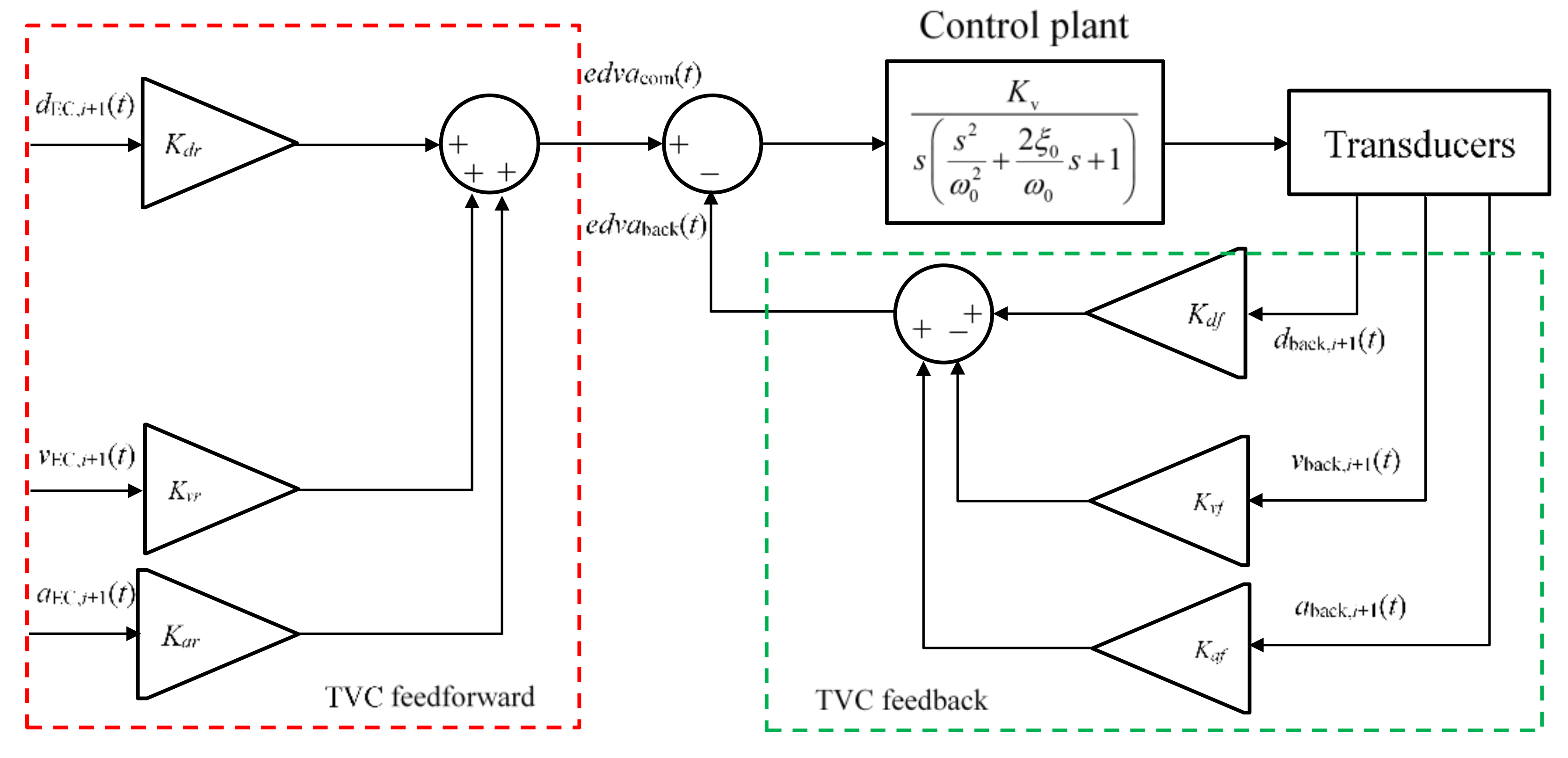
As shown in Figure 1, the conventional TVCM for the shaking table consists of a three-variable feedback control (TVC feedback) and a three-variable feedforward control (TVC feedforward). The TVC feedback aims to assign the poles of the controlled system by feeding back the displacement, velocity, and acceleration of the shaking table. In such a way, a desirable performance in terms of the response rate, table resonant frequency, and damping ratio can be achieved. In Figure 1, K d r , K v r , and K a r denote the displacement, velocity, and acceleration feedforward gains, respectively. The TVC feedforward control further improves the system performance by eliminating the comparatively slow poles of the system. The open-loop transfer function from the driven voltage on the servo-valve to the shaking table displacement, known as the control plant, can be modeled as a third-order system:
W 0 s = K v s s 2 ω 0 2 + 2 ξ 0 ω 0 s + 1 ,
where K v denotes the open-loop gain of the hydraulic system, s means the Laplace operator, and ξ 0 and ω 0 represent the natural damping ratio and resonant frequency of the hydraulic system, respectively. By introducing the TVC feedback for the control plant, as shown in Figure 1, the closed-loop transfer function of the system from the input displacement command U to the displacement response output x can be written as follows:
W s = 1 K d f 1 1 + K v K v f K v K d f 1 ω 0 2 1 + K v K v f s 2 + 2 ξ 0 ω 0 + K v K a f 1 + K v K v f s + 1 s + 1 ,
where K d f , K v f , and K a f denote the displacement, velocity, and acceleration feedback gains, respectively. This transfer function can be rearranged as follows:
W ( s ) = 1 K d f 1 1 k 0 1 ω 2 s 2 + 2 ξ ω s + 1 s + 1 ,
with:
k 0 = K d f 1 + K v K v f K v ,
ω = ω 0 1 + K v K v f ,
ξ ω = 0.5 K v K a f ω 0 2 + ξ 0 ω 0 ,
where k 0 , ω , and ξ are the desired equivalent open-loop gain, frequency, and damping ratio of the system under TVC. Clearly, K v , ξ 0 , and ω 0 are determined by the physical properties of the system; it is impossible for users to change them. Conversely, the equivalent characteristics can be realized by tuning the feedback gains, i.e., K d f , K v f , and K a f . In a conventional STT, according to Equation (14), with an increase in K v f , the equivalent resonant frequency increases. The equivalent damping ratio is proportional to K a f ; hence, a larger K a f indicates the suppression of the response oscillation and the enhancement of stability and robustness. According to Equation (13), the K d f value is normally heightened to suppress the adverse influence of the increase in K v f on the response rate. In summary, by increasing K d f , K v f , and K a f in a certain range, the control performance of the shaking table system can be improved. However, a too large K d f often leads to an oscillation response; therefore, the three feedback gains should be carefully designed.
A reduction in the velocity gain K v f in a certain range can lead to a small frequency ω and large k 0 and ξ . Therefore, for the case where a small ω is acceptable, the control performance can be enhanced by reducing the velocity gain K v f . Consequently, satisfactory performance is achieved with relatively small gains, avoiding the degradation in robustness due to large gains. The TVC feedforward eliminates the slow poles of the system controlled by the TVC feedback. This feedforward control can improve the system response rate, and hence, improve the tracking accuracy. When using the TVC-VPF, the TVC feedback gains in terms of K d f , K v f , and K a f should be determined according to the desired performance and the physical properties of the system; furthermore, the TVC feedforward gains in terms of K d r , K v r , and K a r were determined by eliminating the comparatively slow poles of the system.

3.2. TVCM-VPF for STST

STST with the ES corresponding to the top stories is more challenging than the actuator-based RTHS because of the need for velocity and acceleration control. That is, the reliability of the test results heavily depends on the control accuracy of velocity and acceleration rather than the displacement. In contrast to the traditional STT, testing errors in STST can accumulate and propagate in the subsequent steps owing to the numerical solution of the NS. Moreover, the desired targets in STST are the dynamic responses of the structure at the interface; that is, the frequencies of the loading targets are normally not high. In other words, the required bandwidth of the loading control is not the key element in STST; conversely, the control accuracy and stability should be very favorable. To ensure the robustness of the system, appropriate parameters must be chosen. This study aimed to conduct STST with an old shaking table by enhancing its traditional proportional integral derivative (PID) control performance with the TVCM.
The PID controller is one widely used linear controller and the control parameters are the proportional gain, derivative time, and integral time [46]. The PID controller transforms the error signal to the command signal. The error signal is normally chosen as the difference between the target displacement and measured displacement response of the shaking table, which aims to be reduced with control. The advantage of the PID controller is it is easy to understand and operate. The disadvantage of the method is the control target is solely the displacement regardless of the velocity and acceleration. However, the displacement, velocity, and acceleration are all key elements for the STST. In view of this, the PID controller is not a good choice for the STST and this paper proposes one TVCM-VPF.
In view of the aforementioned low requirement to control the frequency and high requirement to control the accuracy and stability in STST, this study presents a VPF control rather than the commonly used velocity negative feedback control. In the TVCM-VPF, replacing the K v f in Equations (13)–(15) with     K v f yields the following:
k 0 = K v K d f 1     K v K v f ,
ω = ω 0 1     K v K v f ,
ξ ω = 0.5 K v K a f ω 0 2 + ξ 0 ω 0 .
Clearly, compared with Equation (13), the open-loop gain in Equation (16) substantially rises with the increase in gain K v f . However, the equivalent resonant frequency decreases and the equivalent damping ratio improves with the increase in gain K v f according to Equations (17) and (18). That is, in view of the control requirements of STST, the TVFC with a positive velocity feedback is expected to perform satisfactorily.
Similar to the traditional TVCM, the TVC feedforward can be designed to eliminate the slow poles of the controlled system to further improve the response rate, which is not elaborated here. Notably, to obtain a stable response, K v f should be so small that 1     K v K v f > 0 . Additionally, the controlled system is third order, and its stability condition can be obtained by means of Routh’s criterion, i.e., k 0 < 2 ξ 0 ω 0 .

3.3. Implementation Procedures

The block diagram of the proposed STST based on the TVCM-VPF is presented in Figure 2. When conducting STST with the integration algorithm of the CDM, the following procedures are recommended:
(1)
Initialize the experimental parameters, e.g., M N , C N , K N , Δ t , F i .
(2)
Calculate the displacement d N , i + 1 using Equation (4) at the initial sampling instant of the (i + 1)th integration time step with the measured reaction force F E , i and the known F i ,   d N , i ,   d N , i 1 .
(3)
Update the velocity v N , i and acceleration a N , i at the ith step using Equations (2) and (3).
(4)
Determine the target acceleration of the specimen a EC , i + 1 using Equation (6).
(5)
Calculate the target displacement d EC , i + 1 ( t ) and target velocity v EC , i + 1 ( t ) using Equations (5) and (9) at each sampling time t with the calculated d N , i + 1 I .
(6)
Generate the actuator command at each sampling time t with the TVCM, i.e., the feedforward block and the feedback block, loading the shaking table.
(7)
Go back to Step (5) until the end of each integration time interval.
(8)
Measure the corresponding reaction force and return to Step (2) until the end of the test.

4. Experimental Validation of STST Based on TVCM-VPF

4.1. Prototype Structure

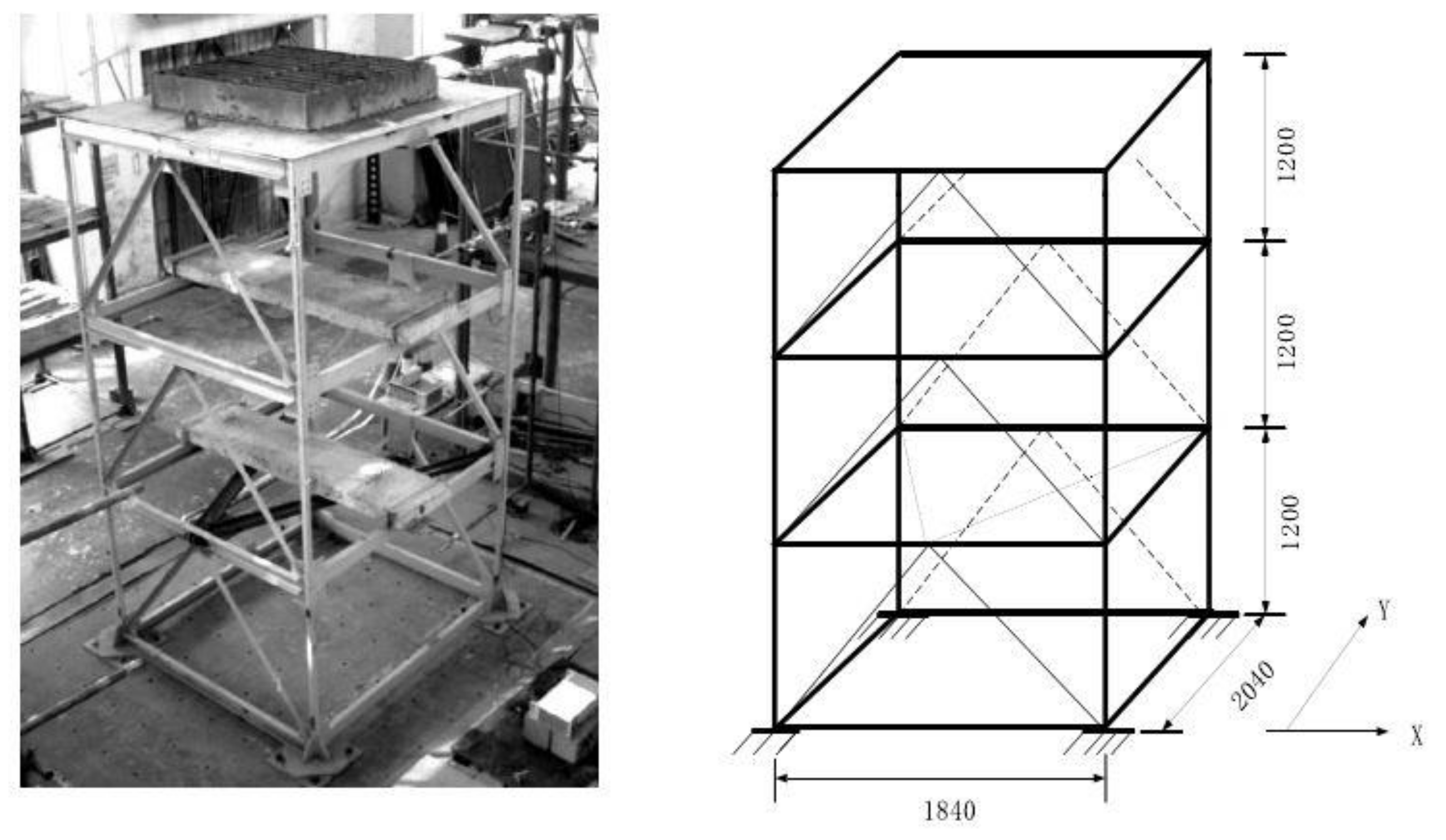
A three-story steel frame structure with a TLD was chosen as the prototype structure to validate the effectiveness of the proposed method. The structure has spans of 1840 mm in the X direction and 2040 mm in the Y direction, and an inter-story height of 1200 mm, as shown in Figure 3. This frame was composed of Q235-grade steel with a yield strength of 235 MPa, and an elastic modulus of 206 GPa. The columns were made up of square steel tubes, each 40 × 40 × 3 mm, and the beams were formed by U-shaped steel, each 100 × 50 × 5 mm. Two vertical herringbone braces consisting of steel angles, each of 40 × 40 × 3 mm, were arranged in the X direction of each story to suppress the torsional rotation around the vertical axis of the structure. A herringbone brace was arranged in the horizontal plane of each floor to improve the floor stiffness. Each brace was rigidly connected to the frames or beams. The structure was excited by earthquake excitations and tested in the Y direction.
Concrete block masses of 250 kg were placed on the first and second floors of the frame to simulate the weight on each floor. One TLD was welded on the third floor of the frame. The total mass of the TLD and the fixed bottom plate was approximately 252 kg, used as the third-floor counterweight. The total mass of the whole frame was approximately 1120 kg. The fundamental circular frequency of this frame structure in the Y direction was ω 1 = 17.9   rad / s , obtained by the spectrum analysis of the structure under a white noise excitation test on the shaking table.
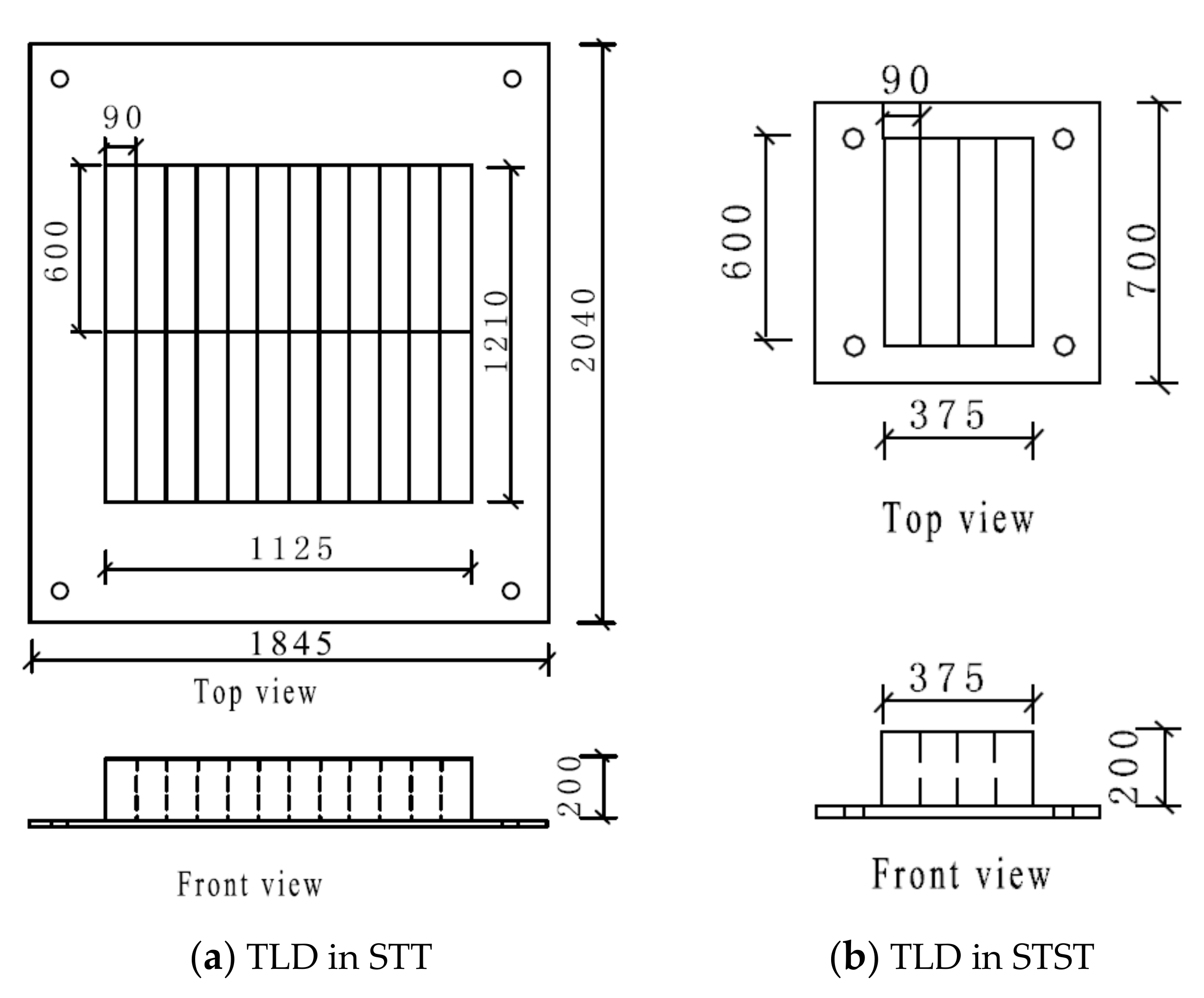
The TLD was well designed according to the optimal control effect for the three-story frame structure; the configuration of the TLD is shown in Figure 4. To control the fundamental vibration mode of this frame, the fundamental sloshing frequency of the liquid in the TLD should be consistent with that of the structure. The single water tank was designed with a = 90   mm along the Y direction, b = 600   mm along the X direction of excitation, and a height of 200 mm. The water depth in the tank, h = 40   mm , was determined to ensure the fundamental circular frequency of the frame as ω 1 = 17.9   rad / s . In the frame structure, the TLD was composed of 24 water tanks to meet the expected mass ratio requirement of 4%.

4.2. Method and System of STST Based on TVC-VPF

4.2.1. Strategy of STST

When conducting the STST, the TLD was chosen as the ES loaded with one shaking table, and the three-story frame structure was regarded as the NS. The two substructures interacted at the boundary in terms of the equilibrium of interface shear forces and the compatibility of interface deformations. The STST block diagram of the three-story frame structure with the TLD is depicted in Figure 5. The system mainly includes a real-time calculation system, controller, shaking table, TLD specimen, and data acquisition computer. The real-time calculation system conducts a step-by-step numerical calculation, that is, the proposed explicit CDM on the NS and the TVC feedforward to generate the displacement command for the controller of the shaking table system. This embedded controller generates and drives the shaking table to track the desired displacement. The data acquisition computer collects the displacement and acceleration responses of the shaking table for the three-variable controller and measures the shear force and acceleration from the specimen for a real-time calculation system.
The block diagram of STST using the proposed explicit CDM for the three-story frame structure with TLD is depicted in Figure 5 and Figure 6. The experiments in this study were conducted with a 3 × 4 m shaking table at the Structural and Seismic Testing Center, Harbin Institute of Technology. This old shaking table is mainly composed of a Schenck servo-hydraulic actuator, a hydraulic power unit, and an MTS controller. This table was originally designed in the displacement control mode with a traditional PID controller. In contrast to existing research on STST using electromagnetic shaking tables, this study was performed on a considerably large and old hydraulic shaking table, which implies that this study was extremely challenging to conduct; therefore, this method can be viewed to have realistic applications. The NS and the realization of the TVCM-VPF were programed and calculated by the Calculation Editor module of the MTS FlexTest GT controller software. The sampling and calculation frequency of the calculation editor module is 2048 Hz. The parameter values of the TVCM-VPF in STST are presented in Table 1.

4.2.2. Characteristics of the NS

The TLD was designed such that the frame structure exhibits a linear performance under rare earthquake excitations. Therefore, a simplified linear three-degree-of-freedom (3DOF) mass-stiffness-damping model was adopted to simulate the NS in STST. The fundamental frequency and the fundamental damping ratio of the steel frame structure was 17.9   rad / s and 0.35%, which were obtained through preliminary tests. The frame was simplified to a shear-type numerical model with three degrees of freedom. Its mass, stiffness, and damping matrices can be expressed as follows:
M N = 400.06 0 0 0 355.50 0 0 0 357.50   kg ,   K N = 1173000 586500 0 586500 1173000 586500 0 586500 586500   N / m ,
C N = 39.1548 2.7212 0.2753 2.7212 34.4612 2.9367 0.2753 2.9367 37.3788   N · s / m .

4.2.3. ES and Shear Force Measurement

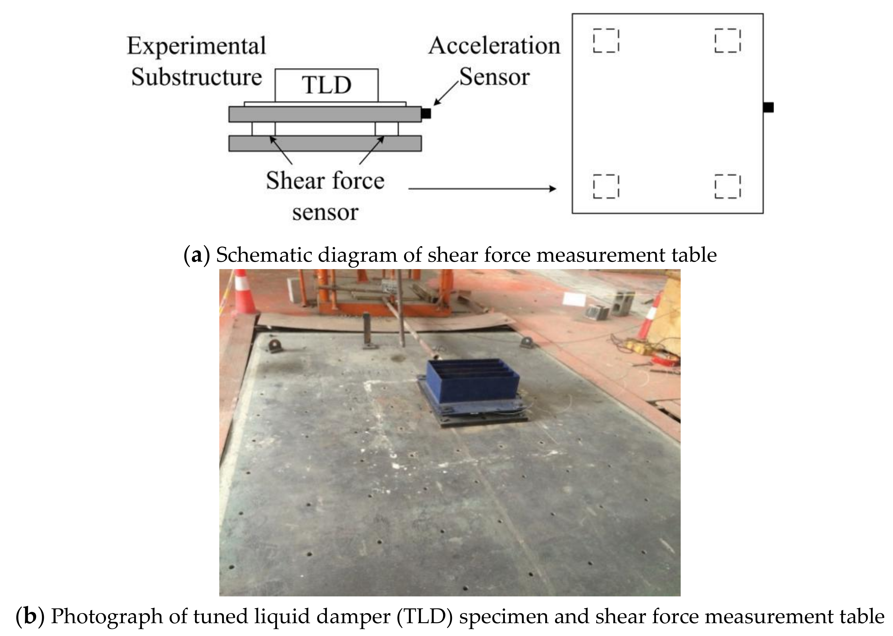
The geometry of the single water tank used in STST is the same as that in the prototype structure. However, owing to the limitation of the size and bearing capacity of the shear force measurement platform used in the substructure test, four single water tanks, as shown in Figure 6, were employed in the substructure tests in this study. To recover the reaction force of the prototype TLD, the measured reaction force of the TLD specimen was multiplied by 6 and then fed back to the evaluation of the NS.
When conducting STST for the TLD control structure, it is necessary to measure the shear force at the bottom of the specimen to calculate the loading targets at the next step. In this study, the shear force of the TLD was obtained directly by a shear force measurement table. A schematic diagram of this measurement table is depicted in Figure 6. This table consists of four shear force sensors, upper and lower high-strength steel plates, accelerometers, and a charge amplifier. Four piezoelectric shear force sensors, model 9146BA of Kistler Company, Winterthur, Switzerland, were arranged between these two plates at the four corners of the table. A capacitive acceleration sensor, model 8310B of Kistler Company, Switzerland, was installed on the upper plate. The shear force F E generated by the TLD specimen was determined by subtracting the inertia force of the upper table from the total shear force:
F E = F Total     m Top a Up ,
where F Total is the total shear force obtained from the measurement table, m Top is the mass of the upper steel plate, and a Up is the acceleration measured by the accelerometers installed on the upper plate.

4.3. Results of STST Based on TVCM-VPF

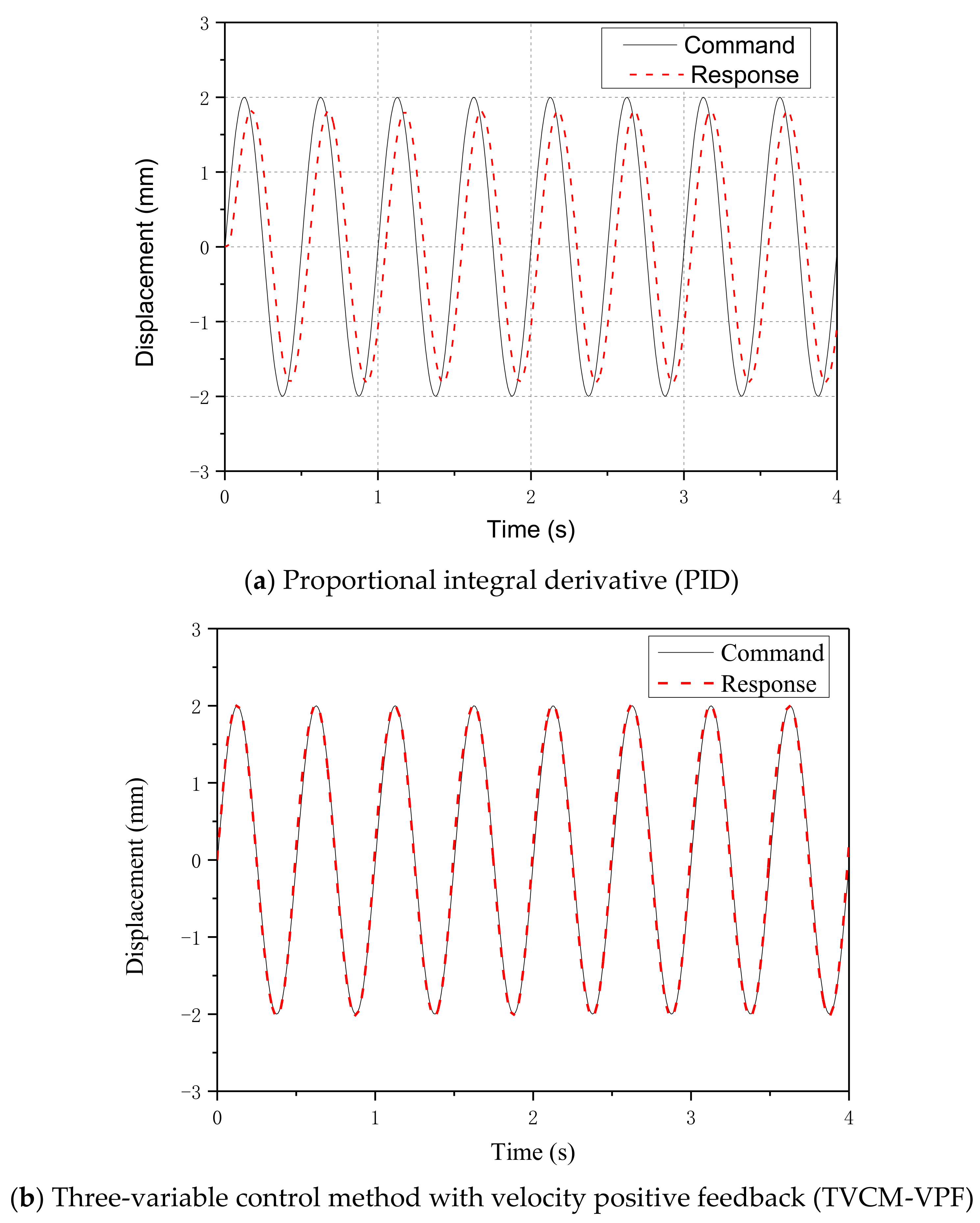
Traditional STT with predefined loading targets and STST with the TVCM-VPF were conducted to validate the effectiveness of the proposed method and determine the advantages of the proposed method over the traditional PID controller. Figure 7 presents the experimental results of sine wave target (command) tests with an amplitude of 2 mm and a frequency of 2 Hz. It can be observed that the results of the TVCM-VPF match the command displacement much better than those of the PID controller. Loading delays associated with Figure 7a,b were 48.41 and 7.53 ms, meaning a decrease of 84.45% owing to the proposed scheme. The corresponding error analysis results are listed in Table 2. Compared with the PID controller, the correlation coefficient of the displacement response for the 2 Hz sine wave tests increased from 83.81% to 99.36% with the contribution of the TVCM-VPF; the amplitude error reduced from 11.4% to 0.53%. Compared with the traditional PID controller, in STST with the TVCM-VPF, the correlation coefficient of the displacement response for the 4 Hz sine wave tests increased from 65.32% to 99.21%; the amplitude error reduced from 33.7% to 0.83%. The results indicate the advantage of the TVCM-VPF over the traditional PID controller, especially for moderately high frequencies.
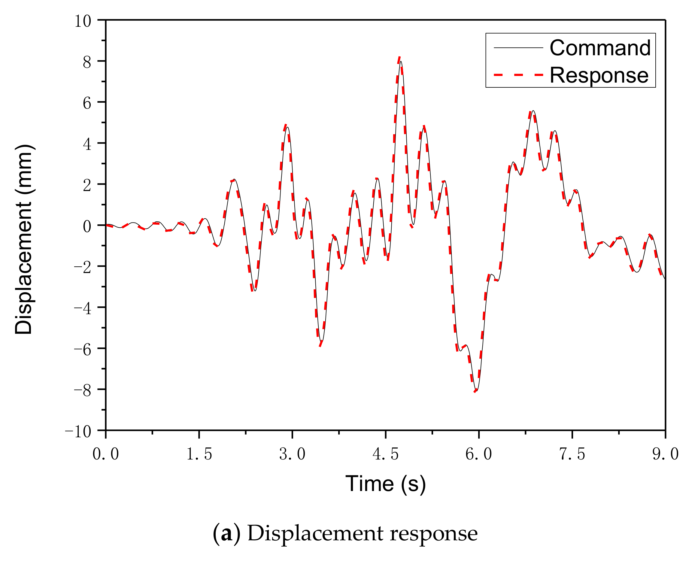
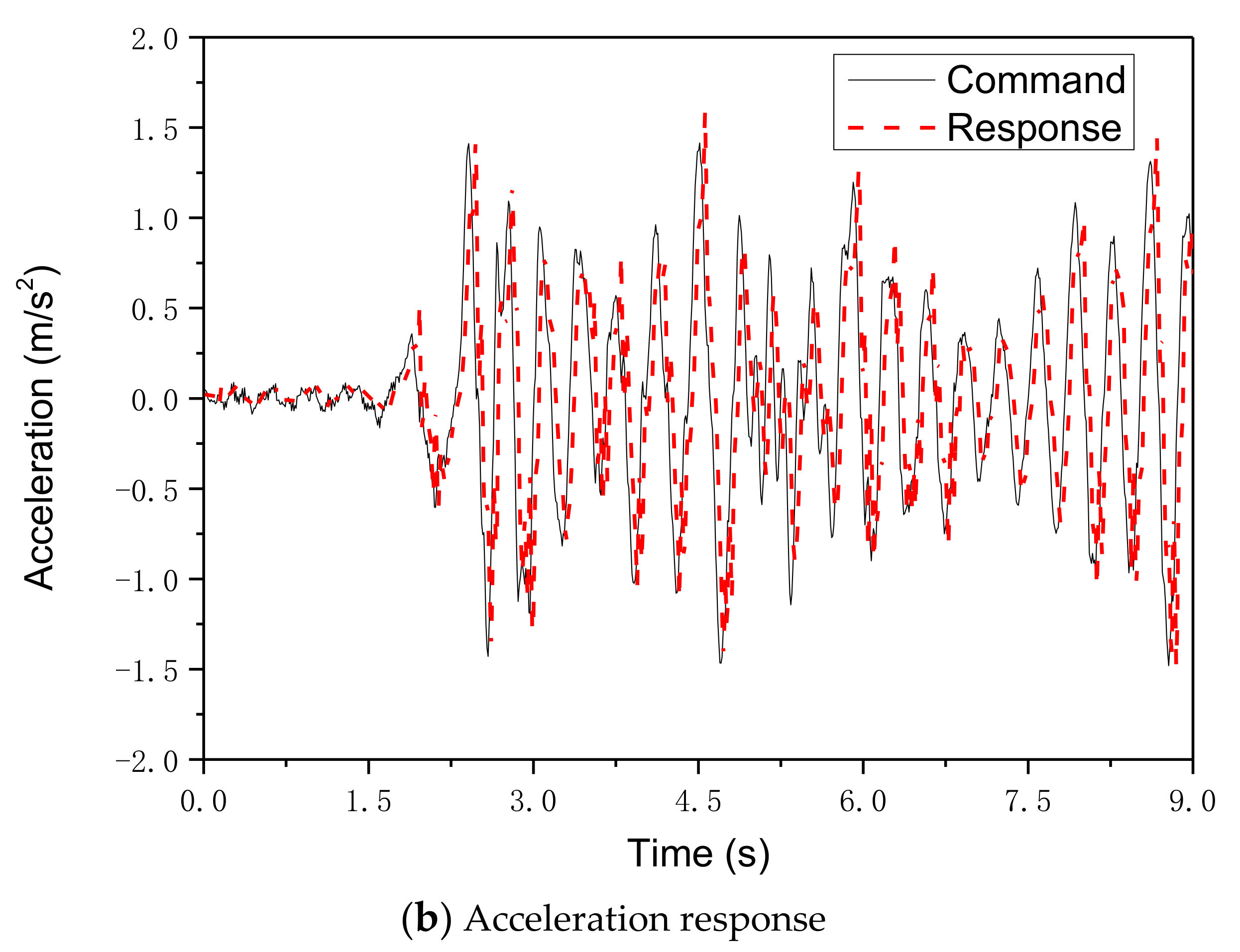
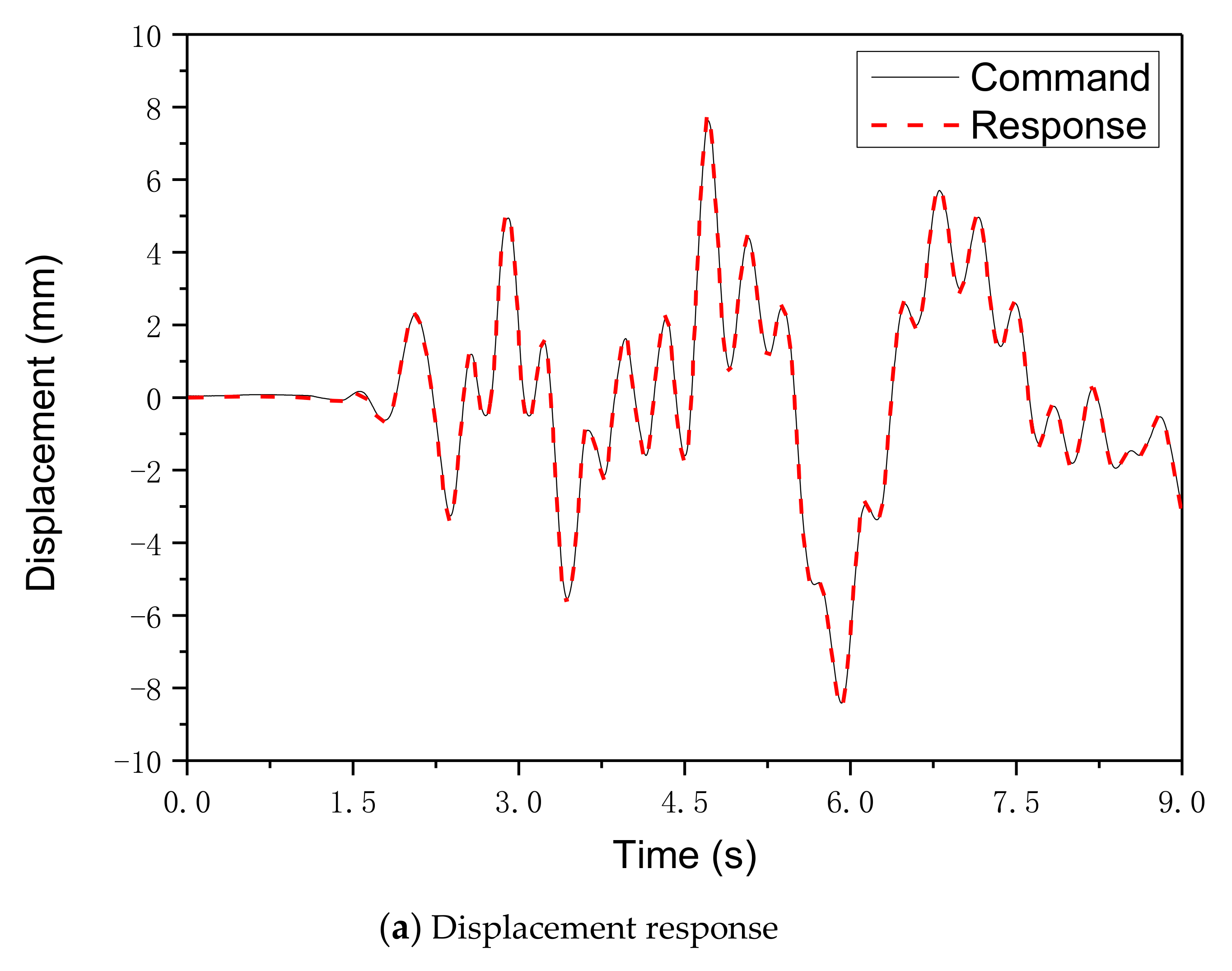
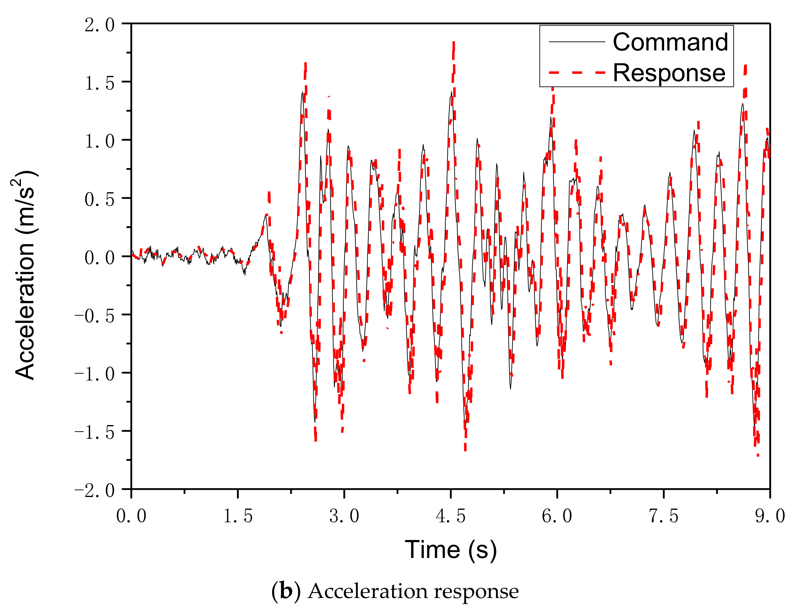
STST with the TVCM-VPF was conducted to validate the advantages of the proposed method over the traditional PID controller. The experimental results of the displacement and acceleration responses on the top floor of the frame structure subjected to the El Centro (NS, 1940) earthquake wave record with a peak ground acceleration of 0.35 m/s2 are presented in Figure 8 and Figure 9 for the two control methods. In these figures, the command means the loading target of the shaking table, and the response represents the measured response of the shaking table. It can be observed from Figure 8 that under the conventional PID control, the displacement response nearly overlaps the displacement command of the shaking table; however, there is an obvious error between the acceleration response and the acceleration command of the shaking table. Conversely, from Figure 9 of the proposed TVCM-VPF, good matching of the responses and commands in terms of displacement and acceleration can be observed. With the contribution of the TVCM-VPF, the time delay between the displacement response and command is clearly reduced. The method can not only address the problem of displacement delay in the shaking table but can also eliminate the displacement overshoot caused by velocity feedforward compensation. The response rate and control accuracy were clearly improved. The corresponding control error indexes are listed in Table 3. From this table, it can be observed that the accuracy of the acceleration and displacement waveform reconstruction under the TVCM is significantly improved compared with that of PID control; in other words, the acceleration correlation coefficient increases from 67.73% to 90.22% with the contribution of the TVCM-VPF. By fine-tuning the control parameters, the TVCM-VPF has improved the performance in terms of accuracy and robustness.

4.4. Comparison between STST and Conventional STT

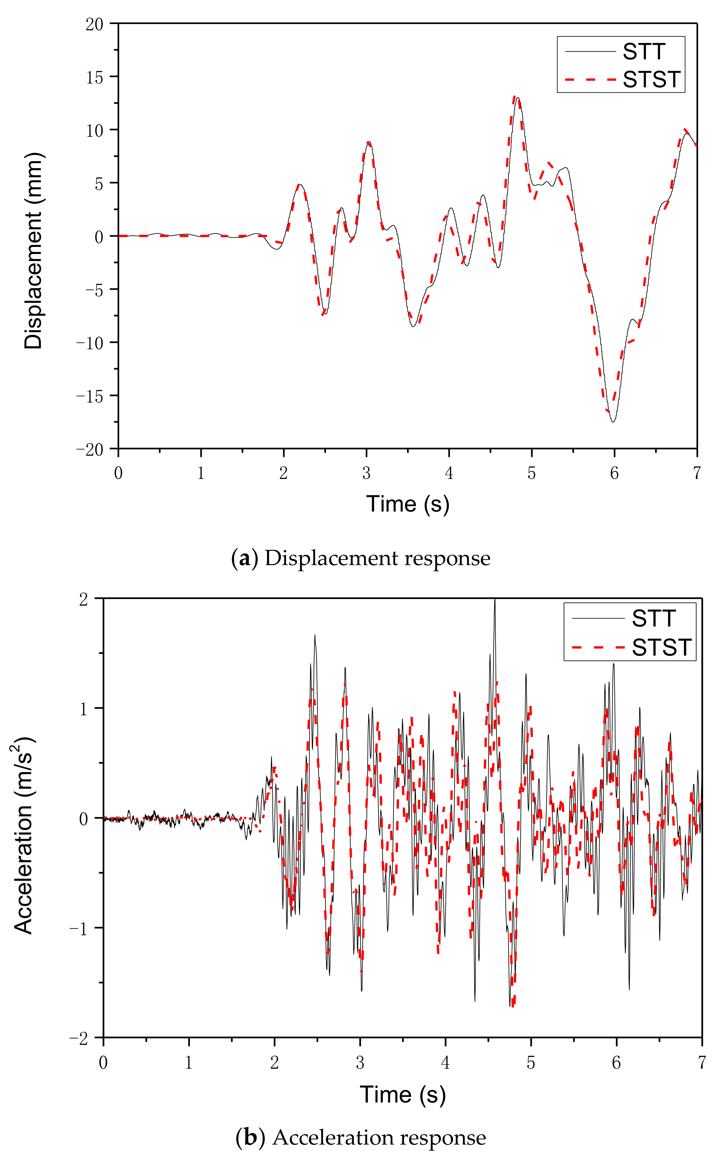
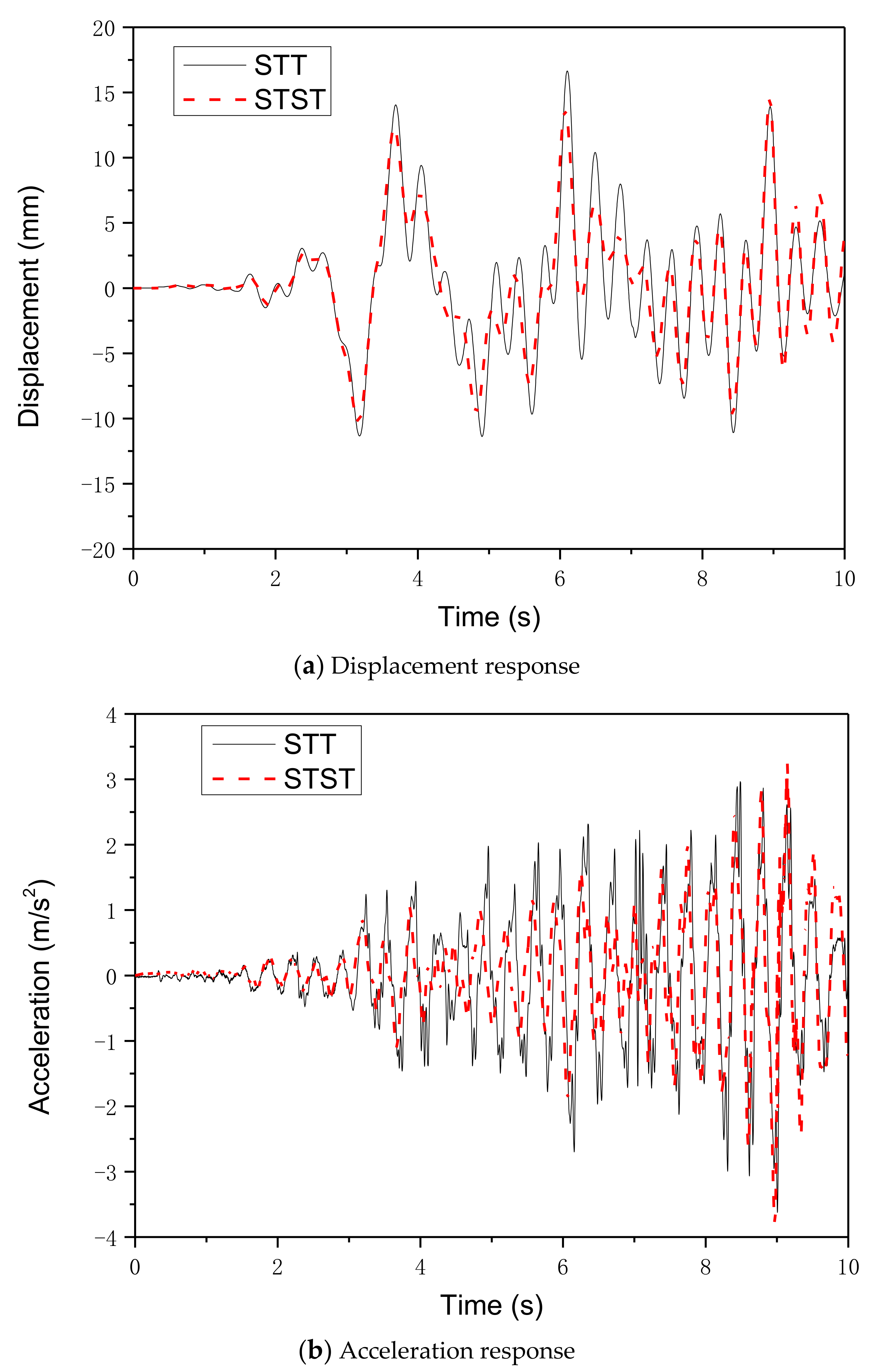
To further validate the effectiveness of the proposed method, a comparison between STST and the conventional full structure STT was conducted. The TLD frame structure under the excitation of the El Centro (NS, 1940) and Taft earthquake wave records with a peak ground acceleration of 0.70 m/s2 were investigated using the two methods. The STT and STST were conducted with the proposed TVC-VPF control, and the input motion in the STST was the measured acceleration response of the shaking table in the corresponding STT. The experimental results of the conventional full structure SST were regarded as the reference solution. The results of STST based on the TVCM-VPF were expected to be close to the reference solutions of the conventional full structure STT. The displacement and acceleration response histories of the top floor of the frame structure subjected to these two simulated earthquakes are shown in Figure 10 and Figure 11. It can be observed from Figure 10 and Figure 11 that the displacement and acceleration response histories of STST based on the TVCM-VPF are in good agreement with those of conventional STTs.
The performance indicators in terms of amplitude deviation and the correlation coefficient of the displacement and acceleration responses for the two types of tests are summarized in Table 4. From this table, it can be observed that the amplitude deviations of the displacement responses of the top floor of the frame structure are 4.48% and 12.17% for the two earthquakes, and the amplitude deviations of the acceleration responses are 11.38% and 4.84% for the two earthquakes. The correlation coefficients of the displacement responses are 97.39% and 92.03%, whereas the correlation coefficients of the acceleration responses are 66.21% and 65.47%, respectively. The results show that the displacement results of STST based on the TVCM-VPF are very close to those of the conventional full structure STT. However, the acceleration results of the former are not in good agreement with the precise solutions of the latter. There are two reasons for this. First, a simplified 3DOF model was used for the numerical calculation of the three-story frame structure in STST, which inevitably induces errors. Second, the loading facility, i.e., the shaking table at the Harbin Institute of Technology, is considerably old. It was a challenge to conduct such sophisticated STST using an old and large-scale shaking table. Although several cases of STST with good performance have been reported, the loading facilities are all newly developed small-scale shaking tables with sophisticated controllers. Therefore, the contribution of this paper is the proposal of a TVCM-VPF for STST, and the realization of the method with an old and large-scale shaking table originally designed using the traditional displacement control mode. The proposed TVCM-VPF is a reliable experimental strategy for evaluating the seismic performance of civil engineering structures, such as a frame structure with TLD. The proposed method has broad application prospects in the performance evaluation of dynamic systems in the fields of structural engineering, offshore platform, bridge engineering, human–structure interaction system, and the vehicle–bridge vibration system, etc.

5. Conclusions

An explicit CDM and TVCM-VPF were proposed to improve the experimental accuracy and stability of STST. The effectiveness of the proposed method was validated by performing the STST on a three-story frame structure with TLD. The main conclusions are as follows:
An explicit CDM for STST based on the CDM for dynamic RTST was proposed to improve the simulation accuracy of boundary conditions between the NS and ES. The proposed CDM provides explicit loading targets for the servo-hydraulic actuators in terms of displacement, velocity, and acceleration, and hence, an improved control accuracy of the boundary conditions is expected to be realized.
The TVCM-VPF was proposed for the STST to achieve high stability and accuracy control of the desired displacement, velocity, and acceleration targets. Compared with the traditional PID control method, the proposed TVCM-VPF can achieve an improved control performance in terms of the stability and response rate owing to the contribution of the positive velocity feedback. This indicates that the TVCM-VPF can be effectively used for STSTs.
Experiments on a three-story frame structure with a TLD were conducted to validate the effectiveness of the proposed methods for STST. Compared with the traditional PID control method, the response rate and control accuracy of the shaking table were significantly improved with the contribution of the TVCM-VPF. The STST results indicated that the accuracy of the acceleration and displacement waveform reproduction under TVCM were significantly improved compared with that of the PID control. To further validate the effectiveness of the proposed method, a comparison was performed between the STST based on the TVCM-VPF and the conventional full structure STT. The results showed that the displacement response results of the proposed STST are very close to those of the STT. This comparison reveals that STST based on TVCM-VPF performs well in terms of accuracy and is a reliable experimental strategy for evaluating the seismic performance of civil engineering structures.
Consequently, the proposed method has broad application prospects in the performance evaluation of dynamic systems in the fields of structural engineering, offshore platform, bridge engineering, human–structure interaction system, and the vehicle-bridge vibration system, etc.

Author Contributions

Conceptualization, G.X. and B.W.; Data curation, Y.B.; Methodology, G.X. and Z.W.; Project administration, G.X. and B.W.; Validation, Y.B. and G.Y.; Writing-original draft, G.X.; Writing-review and editing, G.X. and Z.W. All authors have read and agreed to the published version of the manuscript.

Funding

The National Natural Science Foundation of China (Grant Nos. 51778190, 51978213) and the National Key Research and Development Program of China (Grant No. 2017YFC0703605, 2016YFC0701106).

Conflicts of Interest

The authors declare no conflict of interest.

Nomenclature

Symbols
M N Mass matrices of the NS
C N Damping matrices of the NS
K N Stiffness matrices of the NS
iIntegration time step
F E Reaction force vector of the ES
F External excitation force vector
a N Acceleration response vectors of the NS
v N Velocity response vectors of the NS
d N Displacement response vectors of the NS
Δ t Integration time interval
d EC Displacement targets for the specimen
v EC Velocity targets for the specimen
a EC Acceleration targets for the specimen
IInterface DOF of the two substructures
tTime
K d r Displacement feedforward gains
K v r Velocity feedforward gains
K a r Acceleration feedforward gains
K v Open-loop gain of the hydraulic system
sLaplace operator
ξ 0 Natural damping ratio of the hydraulic system
ω 0 Resonant frequency of the hydraulic system
UDisplacement command input
xDisplacement response output
K d f Displacement feedback gains
K v f Velocity feedback gains
K a f Acceleration feedback gains
k 0 Desired equivalent open-loop gain of the system under TVC.
ω Desired frequency of the system under TVC.
ξ Desired damping ratio of the system under TVC.
F E Shear force
F Total Total shear force obtained from the measurement table
m up Mass of the upper steel plate
a Up Acceleration measured by the accelerometers installed on the upper plate.
Abbreviations
STSTShaking table substructure testing
TVCMThree-variable control method
VPFVelocity positive feedback
RTHSReal-time hybrid simulation
ESExperimental substructure
NSNumerical substructure
TLDTuned liquid damper
STTsShaking table tests
RTSTReal-time substructure testing
DOFDegree of freedom
PIDProportional integral derivative

References

  1. Nakashima, M.; Kato, H.; Takaoka, E. Development of real-time pseudo dynamic testing. Earthq. Eng. Struct. Dyn. 1992, 21, 79–92. [Google Scholar] [CrossRef]
  2. Horiuchi, T.; Inoue, M.; Konno, T.; Namita, Y. Real-time hybrid experimental system with actuator delay compensation and its application to a piping system with energy absorber. Earthq. Eng. Struct. Dyn. 1999, 28, 1121–1141. [Google Scholar] [CrossRef]
  3. Williams, M.S.; Blakeborough, A. Laboratory testing of structures under dynamic loads: An introductory review. Philos. Trans. R. Soc. A Math. Phys. Eng. Sci. 2001, 359, 1651–1669. [Google Scholar] [CrossRef]
  4. McCrum, D.; Williams, M. An overview of seismic hybrid testing of engineering structures. Eng. Struct. 2016, 118, 240–261. [Google Scholar] [CrossRef] [Green Version]
  5. Chae, Y.; Park, M.; Kim, C.Y.; Park, Y.S. Experimental study on the rate-dependency of reinforced concrete structures using slow and real-time hybrid simulations. Eng. Struct. 2017, 132, 648–658. [Google Scholar] [CrossRef]
  6. Wang, Z.; Wu, B.; Xu, G.; Bursi, O.S. An improved equivalent force control algorithm for hybrid seismic testing of nonlinear systems. Struct. Control Healthy Monit. 2017, 25, e2076. [Google Scholar] [CrossRef]
  7. Zhang, Z.; Basu, B.; Nielsen, S.R. Real-time hybrid aeroelastic simulation of wind turbines with various types of full-scale tuned liquid dampers. Wind. Energy 2018, 22, 239–256. [Google Scholar] [CrossRef]
  8. Wu, T.; Lund, A. Real-time aerodynamics hybrid simulation: Wind-induced effects on a reduced-scale building equipped with full-scale dampers. J. Wind. Eng. Ind. Aerodyn. 2019, 190, 1–9. [Google Scholar] [CrossRef]
  9. Tang, Z.; Dietz, M.; Hong, Y.; Li, Z. Performance extension of shaking table based real time dynamic hybrid testing though full state control via simulation. Struct. Control Health Monit. 2020. under review. [Google Scholar] [CrossRef]
  10. Wu, B.; Xu, G.; Wang, Q.; Williams, M.S. Operator-splitting method for real-time substructure testing. Earthq. Eng. Struct. Dyn. 2006, 35, 293–314. [Google Scholar] [CrossRef]
  11. Ahmadizadeh, M.; Mosqueda, G.; Reinhorn, A.M. Compensation of actuator delay and dynamics for real-time hybrid structural simulation. Earthq. Eng. Struct. Dyn. 2007, 37, 21–42. [Google Scholar] [CrossRef]
  12. Gao, X.; Castaneda, N.; Dyke, S.J. Real time hybrid simulation: From dynamic system, motion control to experimental error. Earthq. Eng. Struct. Dyn. 2013, 42, 815–832. [Google Scholar] [CrossRef]
  13. Ou, G.; Ozdagli, A.I.; Dyke, S.J.; Wu, B. Robust integrated actuator control: Experimental verification and real-time hybrid-simulation implementation. Earthq. Eng. Struct. Dyn. 2014, 44, 441–460. [Google Scholar] [CrossRef]
  14. Eem, S.; Koo, J.H.; Jung, H.J. Feasibility study of an adaptive mount system based on magnetorheological elastomer using real-time hybrid simulation. J. Intell. Mater. Syst. Struct. 2018, 30, 701–707. [Google Scholar] [CrossRef]
  15. Wang, Z.; Xu, G.; Li, Q.; Wu, B. An adaptive delay compensation method based on a discrete system model for real-time hybrid simulation. Smart Struct. Syst. 2020, 25, 569–580. [Google Scholar]
  16. Na, O.; Park, J. Verification of Optimized Real-time Hybrid Control System for Prediction of Nonlinear Materials Behavior with 3-DOF Dynamic Test. Appl. Sci. 2020, 10, 4037. [Google Scholar] [CrossRef]
  17. Wu, B.; Shi, P.; Wang, Q.; Guan, X.; Ou, J. Performance of an offshore platform with MR dampers subjected to ice and earthquake. Struct. Control Health Monit. 2010, 18, 682–697. [Google Scholar] [CrossRef]
  18. Christenson, R.; Lin, Y.Z.; Emmons, A.; Bass, B. Large-Scale Experimental Verification of Semiactive Control through Real-Time Hybrid Simulation. J. Struct. Eng. 2008, 134, 522–534. [Google Scholar] [CrossRef]
  19. Chae, Y.; Ricles, J.M.; Sause, R. Large-scale real-time hybrid simulation of a three-story steel frame building with magneto-rheological dampers. Earthq. Eng. Struct. Dyn. 2014, 43, 1915–1933. [Google Scholar] [CrossRef]
  20. Shao, X.; Lindt, J.V.D.; Bahmani, P.; Pang, W.; Ziaei, E.; Symans, M.; Tian, J.; Dao, T. Real-time hybrid simulation of a multi-story wood shear wall with first-story experimental substructure incorporating a rate-dependent seismic energy dissipation device. Smart Struct. Syst. 2014, 14, 1031–1054. [Google Scholar] [CrossRef]
  21. Hakuto, S.; Park, R.; Tanaka, H. Seismic load tests on interior and exterior beam- column joints with substandard reinforcing details. ACI Struct. J. 2000, 97, 11–25. [Google Scholar]
  22. Laterza, M.; D’Amato, M.; Gigliotti, R. Modeling of gravity-designed RC sub-assemblages subjected to lateral loads. Eng. Struct. 2017, 130, 242–260. [Google Scholar] [CrossRef]
  23. Chen, Z.; Wang, H.D.; Wang, H.; Jiang, H.; Zhu, X.; Wang, K. Application of the Hybrid Simulation Method for the Full-Scale Precast Reinforced Concrete Shear Wall Structure. Appl. Sci. 2018, 8, 252. [Google Scholar] [CrossRef] [Green Version]
  24. Cai, X.; Yang, C.; Yuan, Y. Hybrid Simulation of Seismic Responses of a Typical Station with a Reinforced Concrete Column. Appl. Sci. 2020, 10, 1331. [Google Scholar] [CrossRef] [Green Version]
  25. Horiuchi, T.; Nakagawa, M.; Kasai, H. Fundamental study on real-time hybrid experiment using shaking table. Jpn. Soc. Mech. Eng. 1994, 940, 433–436. (In Japanese) [Google Scholar]
  26. Igarashi, A.; Kikuchi, Y.; Iemura, H. Real-time hybrid experimental simulation system using coupled control of shake table and hydraulic actuator. In Proceedings of the 14th World Conference on Earthquake Engineering, Beijing, China, 12–17 October 2008. [Google Scholar]
  27. Lee, S.K.; Park, E.C.; Min, K.W.; Lee, S.H.; Chung, L.; Park, J.-H. Real-time hybrid shaking table testing method for the performance evaluation of a tuned liquid damper controlling seismic response of building structures. J. Sound Vib. 2007, 302, 596–612. [Google Scholar] [CrossRef]
  28. Lee, S.K.; Park, E.C.; Min, K.W.; Park, J.H. Real-time substructuring technique for the shaking table test of upper substructures. Eng. Struct. 2007, 29, 2219–2232. [Google Scholar] [CrossRef]
  29. Ji, X.; Kajiwara, K.; Nagae, T.; Enokida, R.; Nakashima, M. A substructure shaking table test for reproduction of earthquake responses of high-rise buildings. Earthq. Eng. Struct. Dyn. 2009, 38, 1381–1399. [Google Scholar] [CrossRef]
  30. Nakata, N.; Stehman, M. Substructure shake table test method using a controlled mass: Formulation and numerical simulation. Earthq. Eng. Struct. Dyn. 2012, 41, 1977–1988. [Google Scholar] [CrossRef]
  31. Shao, X.; Reinhorn, A.M.; Sivaselvan, M.V. Real-Time Hybrid Simulation Using Shake Tables and Dynamic Actuators. J. Struct. Eng. 2011, 137, 748–760. [Google Scholar] [CrossRef]
  32. Zhou, M.X.; Wang, J.T.; Jin, F.; Gui, Y.; Zhu, F. Real-Time Dynamic Hybrid Testing Coupling Finite Element and Shaking Table. J. Earthq. Eng. 2014, 18, 637–653. [Google Scholar] [CrossRef]
  33. Lanese, I.; Pavese, A.; Dacarro, F. Development of Software and Hardware Architecture for Real-Time Dynamic Hybrid Testing and Application to a Base Isolated Structure. J. Earthq. Eng. 2012, 16, 65–82. [Google Scholar] [CrossRef]
  34. Ashasi-Sorkhabi, A.; Malekghasemi, H.; Mercan, O. Implementation and verification of real-time hybrid simulation (RTHS) using a shake table for research and education. J. Vib. Control. 2013, 21, 1459–1472. [Google Scholar] [CrossRef]
  35. Tang, Z.; Dietz, M.; Li, Z.; Taylor, C. The performance of delay compensation in real-time dynamic substructuring. J. Vib. Control. 2017, 24, 5019–5029. [Google Scholar] [CrossRef] [Green Version]
  36. Fu, B.; Kolay, C.; Ricles, J.; Jiang, H.; Wu, T. Stability analysis of substructure shake table testing using two families of model-based integration algorithms. Soil Dyn. Earthq. Eng. 2019, 126, 105777. [Google Scholar] [CrossRef]
  37. Fu, B.; Jiang, H.; Wu, T. Experimental study of seismic response reduction effects of particle damper using substructure shake table testing method. Struct. Control Health Monit. 2018, 26, e2295. [Google Scholar] [CrossRef]
  38. Loebach, L.; Ward, C.; Christenson, R.; Seto, K.; Dyke, S.J. A Hybrid Experiment for Examination of Structural Control Considering Soil-Structure Interaction. In Proceedings of the Structures Congress: 17th Analysis and Computation Specialty Conference, St. Louis, MO, USA, 18–21 May 2006. [Google Scholar]
  39. Zhu, F.; Wang, J.T.; Jin, F.; Lu, L.Q.; Gui, Y.; Zhou, M.X. Real-time hybrid simulation of the size effect of tuned liquid dampers. Struct. Control Health Monit. 2016, 24, e1962. [Google Scholar] [CrossRef]
  40. Zhang, R.; Phillips, B.; Taniguchi, S.; Ikenaga, M.; Ikago, K. Shake table real-time hybrid simulation techniques for the performance evaluation of buildings with inter-story isolation. Struct. Control Health Monit. 2016, 24, e1971. [Google Scholar] [CrossRef]
  41. Günay, S.; Mosalam, K.M. Enhancement of real-time hybrid simulation on a shaking table configuration with implementation of an advanced control method. Earthq. Eng. Struct. Dyn. 2014, 44, 657–675. [Google Scholar] [CrossRef]
  42. Luo, L.; Jiang, N.; Bi, J. Analysis of the Effects of Soil on the Seismic Energy Responses of an Equipment-Structure System via Substructure Shaking Table Testing. Shock. Vib. 2019, 2019, 1–11. [Google Scholar] [CrossRef]
  43. Jiang, N.; Luo, L.; Bi, J. Effects of soil on the energy response of equipment–structure systems with different connection types between the equipment and structure. Struct. Des. Tall Spec. Build. 2020, 29, e1735. [Google Scholar] [CrossRef]
  44. Wang, Z.; Ning, X.; Xu, G.; Zhou, H.; Wu, B. High performance compensation using an adaptive strategy for real-time hybrid simulation. Mech. Syst. Signal Process. 2019, 133, 106262. [Google Scholar] [CrossRef]
  45. Wu, B.; Deng, L.; Yang, X. Stability of central difference method for dynamic real-time substructure testing. Earthq. Eng. Struct. Dyn. 2009, 38, 1649–1663. [Google Scholar] [CrossRef]
  46. Kayabekir, A.E.; Bekdaş, G.; Nigdeli, S.M.; Geem, Z.W. Optimum Design of PID Controlled Active Tuned Mass Damper via Modified Harmony Search. Appl. Sci. 2020, 10, 2976. [Google Scholar] [CrossRef]
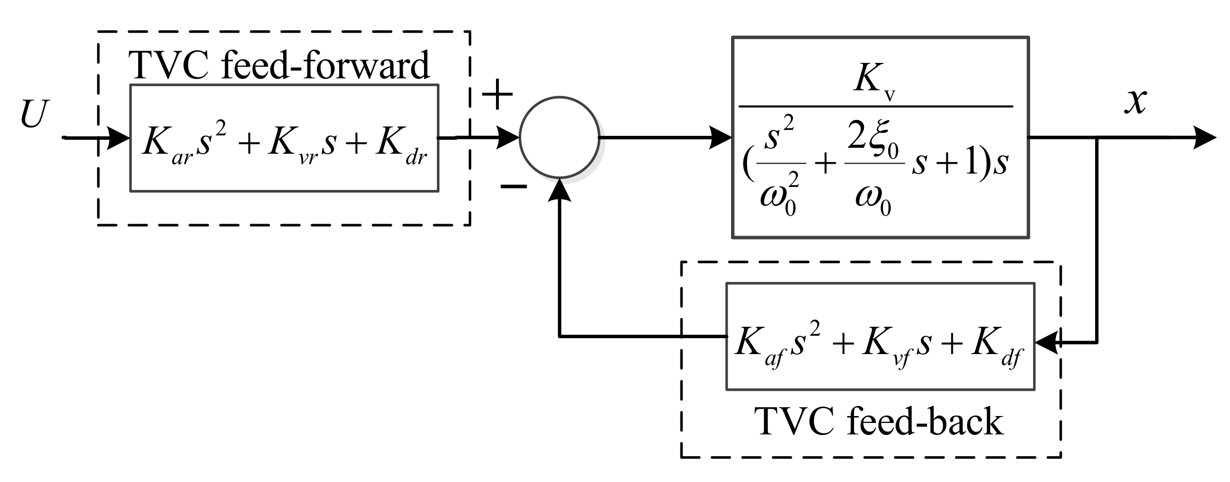
Figure 1. Conventional three variable control for shaking table test (STT).
Applsci 10 05414 g001
Figure 2. Shaking table substructure testing (STST) based on a three-variable control method with velocity positive feedback (TVCM-VPF).
Applsci 10 05414 g002
Figure 3. Schematic diagram of the prototype steel frame.
Applsci 10 05414 g003
Figure 4. Configurations of tuned liquid damper (TLD)in shaking table test (STT) and in shaking table substructure testing (STST).
Applsci 10 05414 g004
Figure 5. Block diagram of shaking table substructure testing (STST) for three-story frame structure with a tuned liquid damper (TLD).
Applsci 10 05414 g005
Figure 6. Specimen and experimental setup.
Applsci 10 05414 g006
Figure 7. Experimental results of the sine wave target test.
Applsci 10 05414 g007
Figure 8. Shaking table substructure testing (STST) results with conventional proportional integral derivative (PID) control.
Applsci 10 05414 g008aApplsci 10 05414 g008b
Figure 9. Shaking table substructure testing (STST) results with a three-variable control method with velocity positive feedback (TVCM-VPF).
Applsci 10 05414 g009aApplsci 10 05414 g009b
Figure 10. Experimental results with the El Centro earthquake.
Applsci 10 05414 g010
Figure 11. Experimental results with the Taft earthquake.
Applsci 10 05414 g011
Table 1. Parameter values of three-variable control method with velocity positive feedback (TVCM-VPF) in shaking table substructure testing (STST).
K d f K v f K a f K d r K v r K a r
0.2−0.020.000060.20.00790
Table 2. Error comparison of the sine wave excitation tests.
Sine Wave (Hz)Amplitude Deviation (%)Correlation Coefficient (%)
PIDTVCM-VPFPIDTVCM-VPF
0.50.440.3799.3499.98
10.730.5598.9599.84
211.40.5383.8199.36
433.70.8365.3299.21
Table 3. Error comparison of earthquake wave excitation tests.
ControllerResponseAmplitude Deviation (%)Correlation Coefficient (%)
PIDDisplacement1.7198.62
Acceleration6.4767.73
TVCM-VPFDisplacement1.5299.88
Acceleration6.6190.22
Table 4. Error comparison between shaking table substructure testing (STST) and the reference shaking table test (STT).
EarthquakeResponseAmplitude Deviation (%)Correlation Coefficient (%)
El CentroDisplacement4.4897.39
Acceleration11.3866.21
TaftDisplacement12.1792.03
Acceleration4.8265.47