1. Introduction
Visuo-haptic mixed reality (VHMR) combines real and virtual objects in the same simulation environment, where a user can see and also touch the objects in the scene. The two sensory modalities not only complement the overall realism of simulation but also cover-up fidelity deficits of each other. For example, visual perception of surface roughness is improved by touch [
1], and haptic perception of stiffness is enhanced by vision [
2] in virtual environments. Medicine is deemed to be one of the most effective application areas of VHMR [
3,
4,
5,
6,
7]. Maintenance training [
8,
9,
10] and product design [
11] are notable others.
The colocation of visual and touch stimuli in VHMR brings new technological challenges that do not exist in conventional delocated virtual reality haptics. If the user interacts with bare hands, then accurate hand tracking is necessary [
12,
13]. Barehand interaction is mostly limited to surface haptics with tactile stimuli [
14,
15]. Although being at an experimental level, wearable devices such as haptic gloves extend the simulation to have kinesthetic feedback [
16,
17,
18]. However, there is then an additional challenge of removing the device from the visual scene or replacing the hand’s view with a virtual one.
Most studies with kinesthetic feedback resort to using commercial haptic devices, where the user continuously holds a stylus connected to the device. There is no need for hand tracking since the device can provide an accurate position and orientation. Nevertheless, visual obstruction caused by these bulky devices is a substantial issue. Chroma-key masking [
4,
19] and visual removal by image processing [
2] of the haptic device are shown to be useful solutions. Once the device is removed from the scene, adding a virtual tool and aligning it with the stylus of the device poses another challenge [
20,
21]. Although the tip (or edge) of the tool interacts with the objects in the scene, its handle is harder to render visually because of the occlusion caused by the user’s hand. Also, the handle you see and the handle you hold do not usually feel the same.
Haptic devices operate in a limited workspace, and they can stably render a limited range of mechanical impedances. Typically, impedance-type devices are better at rendering low inertia, but they are not strong enough for rendering high stiffness. The opposite of this is valid for admittance-type devices. In a VHMR simulation, the user only actually needs haptic feedback when interacting with the objects. Holding a stylus attached to the haptic device at all times constrains the user to the workspace and impedance limits of the device even when it is not needed. This brings us to the motivation of this research.
One of the pioneer teams working on colocated visuo-haptic feedback, Yokokohji et al. [
19], probably had a similar motivation, such that they built an encountered-type haptic display (ETHD) for their work. ETHDs are typically industrial robots that are configured to provide admittance-type haptic feedback. They position their end-effector at the location of the virtual object and wait for the user to “encounter”. Although the original idea in [
19] falls under the augmented reality category, this approach is especially suited for use with virtual reality, where the user only sees the graphically rendered environment [
15]. Studies on ETHDs are limited in number compared to other types of haptic devices, but they focus on barehand interaction in large workspaces. Applications can be categorized into two groups. In the first group, users grasp ETHD’s end-effector, which is a physical prop that represents the virtual object or a portion of it. A pneumatic balloon is used as a prop in [
22] for rendering non-spherical objects, like a human arm, that is approximated by a chain of spheres with different sizes. An industrial plant training scenario with virtual reality is presented in [
23] where the ETHD changes props, such as buttons and valve wheels, as needed. In the second group, users touch wide surfaces with or without curvature. Surfaces with variable curvature are rendered in [
24]. A transparent, flexible plate is manipulated in 4 degrees-of-freedom (DoF) by two 3-DoF parallel robots, based on the position of the user’s finger. Articulated robot arms are used as ETHDs in [
25,
26,
27] for interactions with wide flat virtual surfaces such as walls and desktops. The first two studies use flat, static props, whereas the third demonstrates a multi-textured spinning prop for a richer rendering with sliding and friction sensations.
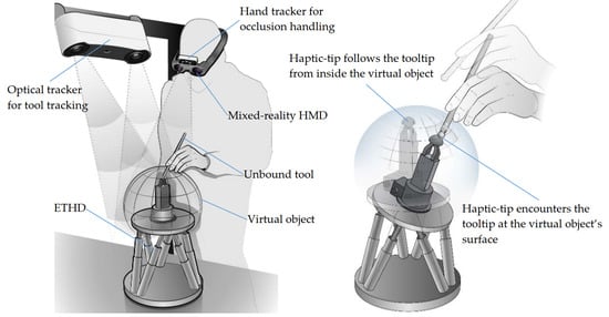
In this paper, we propose a novel VHMR concept with an ETHD (
Figure 1). The main contribution is that the users work with unbound real-life tools in the simulation, and they can change tools like they do in real life. By tool, we mean a handheld instrument such as a scalpel in a surgical simulation or a screwdriver in a maintenance training scenario. The tools have tracking markers and modified tips, but the handles remain intact. The original tooltip is visually overlaid during a simulation. We configured a precision hexapod positioner and a six-axis force/torque transducer as an ETHD. Its end-effector, i.e., the haptic-tip, remains within the boundaries of the virtual object, and it engages with the tooltip only during an interaction. At other times, the user’s hand is unencumbered.
After an overview of our simulation setup in
Section 2, we outline the simulation processes in
Section 3. In
Section 4 we present experiments that assess the accuracy and synchronization of various system components, and also user evaluations. Finally, in
Section 5 we discuss the current and future work.
2. VHMR Simulation Setup
An overview of the VHMR simulation setup is shown in
Figure 2. The tool is tracked by a fixed optical tracker, fusionTrack 250, which has a root mean square (RMS) accuracy of 0.09 mm. The user wears a see-through head-mounted display (HMD), Magic Leap 1, and a Leap Motion Controller. The latter is for hand tracking to fix occlusions when the user’s hand is between the user and the virtual objects. All three components operate up to 120 Hz.
The ETHD consists of three components. A hexapod positioner, PI H-840.D2 (Physik Instrumente GmbH & Co. KG, Karlsruhe, BW, Germany), which has 10 kg payload, 50 mm/s maximum velocity, and 0.5 µm repeatability. An ATI Gamma SI-130-10 force/torque transducer (ATI Industrial Automation, Apex, NC, USA) with a force capacity of 130 N and a resolution of 0.025 N. And a Schunk EGP 50 gripper (SCHUNK GmbH & Co. KG, Lauffen/Neckar, BW, Germany), which is currently used in validation experiments, but it is vital for our future work as discussed in
Section 5. The haptic-tip is at the end of the gripper, and its reachable workspace is 160 × 140 × 50 mm. A hard real-time industrial computer (PC-H in
Figure 2), Beckhoff C6920 (Beckhoff Automation GmbH & Co. KG, Verl, NRW, Germany), controls the ETHD over EtherCAT protocol. Control software was developed in MATLAB/Simulink (R2020a, MathWorks, Natick, MA, USA, 2020) and compiled to run with TwinCAT (Version 3.1, Beckhoff Automation GmbG & Co. KG, Verl, NRW, Germany, 2013) at 1 kHz cycle frequency.
The range of stiffness that can be rendered by the ETHD is determined via a set of unilateral virtual wall experiments, where the wall is modeled as a linear compression spring (
Figure 3a). The haptic-tip is positioned at the virtual wall boundary and constrained to move only in the vertical direction. Then, it is pushed inside the wall by an external force. The apparent stiffness is calculated from the measured force and displacement at steady-state.
Figure 3b shows a plot of the percent error between the actual and commanded stiffnesses for the range from 0.03 N/mm to 200 N/mm. The error bars indicate the maximum and minimum values of three repeated experiments. Stiffnesses below 0.03 N/mm could not be rendered due to unstable behavior of the haptic-tip. High errors and low repeatability were observed up to 0.3 N/mm. After 0.3 N/mm, the error is within ±2%.
Server computer (PC-S in
Figure 2) is a Windows PC for handling data transfer between components with a server application developed in Unity. It has a USB connection with the hand tracker and a 100 Hz user datagram protocol (UDP) connection with the tool tracker, PC-H, and HMD. PC-S also controls the sidescreens with individual cameras on either side of the setup to monitor simulations for development purposes, and also for an audience without HMDs.
Coordinate frames associated with the system components are shown in
Figure 4a. All components are referenced to a world frame {W}. It is chosen such that it coincides with the haptic-tip frame {H} when the hexapod is in zero-configuration. The transformation matrices
,
,
, and
are constant since the respective components are fixed. The HMD continuously references {G} relative to {S}. The hand tracker is fixed to the HMD, hence
is known.
is calculated based on joint variables of the hexapod, and
is constant.
4. Validation Experiments and Results
To validate the proposed VHMR concept, we designed three groups of experiments to assess relative accuracy and synchronization of the three major processes, namely tool tracking, haptic rendering, and visual rendering. The experiments built up to a simple simulation scenario where a tennis ball with a fixed center was deformed by the user.
4.1. Tool Tracking Experiments
The most essential requirement of the proposed concept is that the tooltip and the haptic-tip engage precisely. The nominal accuracy of fusionTrack 250 is 90 µm within 1.4 m [
29], which covers our simulation workspace. The tool’s velocity also affects accuracy [
30]. The hexapod has 3 µm resolution and 0.5 µm repeatability. Therefore, position data from the hexapod was used as a reference in this experiment.
The tool was attached firmly to the gripper at its tip, as shown in
Figure 6. It was moved with 20 mm/s velocity to a distance of 40 mm along the principal axes of {W} and stopped for 5 s at 5, 10, and 20 mm locations. The procedure was repeated at 40 mm/s. The tracker sends measurement data to PC-S, where the server application processes the data and transfers it to PC-H. All communications are over the UDP network at 100 Hz, hence the errors are calculated in PC_H whenever new data is available from the tracker.
Table 1 shows the absolute mean (MAE) and root mean square (RMSE) values of the relative end-to-end tracking error, which includes measurement error, numerical error due to processing, and UDP delay. According to the first two columns, static tracking error when the tool was stationary at 5, 10, 20, and 40 mm locations was less than 0.2 mm. Dynamic tracking error almost doubled from 20 mm/s to 40 mm/s, however, the compound error was less than 1 mm.
4.2. Haptic Rendering Experiments
This group of experiments had two stages. In the first stage, we recorded data from a real-life object, in this case, a tennis ball, to build a simple haptic model. In the second stage, we haptic-rendered a virtual tennis ball based on our model.
We built a test rig to measure force versus deflection from a real-life tennis ball. This data was the basis of our haptic model. The ball was confined just above the haptic-tip, as shown in
Figure 7, and deflected by the hexapod using a spherical probe with a 10 mm radius. The tool tracker was not used in this experiment. The instantaneous position of the probe’s tip was obtained from the hexapod at 1 kHz and recorded alongside the corresponding force vector.
Data was collected for three different indentations of the ball and each experiment was repeated five times. The first indentation (A in
Figure 7) was vertically upwards along the radius of the ball. The second one (B in
Figure 7) was also vertically upwards but 10 mm offset to the center of the ball. The third one (C in
Figure 7) was along the radius of the ball but 10° offset to the vertical axis. As expected, the data shows a hysteresis loop for a press and release cycle. Hence, we fitted two 4th order polynomials for each cycle, i.e., one for press one for release, and used them as reference curves (
Figure 8) in haptic rendering experiments.
In haptic rendering experiments, an experienced user manually replicated the indentations A, B, and C on a virtual tennis ball from above by using a handheld tool.
Figure 9 shows the real and mixed reality views of the indentations. Tool tracking was adapted to guide the user to the correct tool position and orientation. The ETHD limits the user at the maximum deflection (i.e., 6 mm). The instantaneous deflection and the applied force is recorded at every cycle of the haptic loop, which runs at 1 kHz frequency. Results for all indentations show good agreement with the reference curves in
Figure 8. The RMSE and MAE values are listed in
Table 2.
Figure 10 shows the results of five experiments where the user performs the indentation A. Zoomed sections show that the repeatability is within 0.2 N.
4.3. Visual Rendering Experiments
A qualitative approach was followed for tuning the deformation characteristics of the tennis ball model in Unity. The test rig built in the first stage of haptic rendering experiments was also used here but for a different purpose. The confined tennis ball was indented with the spherical probe, and images were acquired at 2, 4, and 6 mm deflections. The same scenario was simulated in Unity with a rigid probe and an elastic ball. The ball’s parameters ware manually tuned until the deformation was similar, as shown in
Figure 11.
We designed a final experiment to evaluate the synchronization between visual and haptic rendering. It should be noted that all processes described in
Section 3 were active during this experiment. The user picked up a tool and indented the virtual tennis ball towards its center, as shown in
Figure 12. The virtual model used the data from the optical tracker to overlay a virtual tooltip and to deform the ball model. In the meantime, the ETHD rendered the ball based on the force applied by the user.
The user was asked to press and release the same point three times. Deflection limits were enforced by the ETHD at 6, 4, and 2 mm respectively. Instantaneous deflection of the contact point, i.e., visual tip, was sent from Unity to PC-H. It was recorded with the haptic-tip’s position, which was obtained from the hexapod. Deflection versus time plots of the haptic-tip and the visual tip are in good agreement in
Figure 13. The MAE and RMSE values were 0.1503 and 0.2089 respectively. Oscillations in the visual tip position (
i in
Figure 13) were mostly due to the typical jitter of the optical tracker [
30] and partly due to the shaking of the user’s hand.
4.4. User Evaluation Experiments
We conducted a face and content validation study in which 15 participants were asked to test the VHMR system with the tennis ball scenario and provide feedback in a questionnaire.
In this test, after being provided with general information about the system, the user wears the HMD and sees the virtual tennis ball. Then, the user is asked to hold any of the two available tools with the dominant hand and indent the tennis ball radially at different locations for two minutes. One tool change is instructed during each experiment.
15 healthy participants took part in the study, with ages between 23 and 50 years (M = 32.9; SD = 8.9). These participants are all engineers with different levels of knowledge and experience in force-feedback, virtual reality/mixed reality (VR/MR), and visuo-haptics. Six (40%) participants had used a force-feedback device before, nine (60%) had not. Seven (47%) of the participants had used VR/MR devices and eight (53%) of them had not. Five (33%) participants had experienced visuo-haptic interaction before, while ten (67%) had not.
An item pool was formed for the questionnaire based on a literature survey. Then the pool was refined, according to the opinions of seven experts in the field, to reflect face and content validity. The final questionnaire in
Figure 14 consists of eleven items. Items 1 to 4 are about the overall simulation approach. Items 5 and 6 focus on haptic perception, while 7 and 8 are on vision. Visuo-haptic coordination is evaluated with items 9 to 11. A seven-step Likert scale was used: (1) Very strongly disagree, (2) Strongly disagree, (3) Disagree, (4) Neutral, (5) Agree, (6) Strongly agree, (7) Very strongly agree.
In general, the questionnaire results (
Figure 14) reflected a positive view on the part of the participants, with a global mean of 5.3 points. Regarding the overall simulation, the users were very positive about the user-friendliness of the VHMR system and they strongly agreed that using unbound tools and freely changing them enhances realism. Item 2 had the lowest mean and widest range of points in the questionnaire. This was expected, since this item questions the simulation in a broader view. One reason for the synthetic opinion may arise from the physical discomfort of wearing an HMD. Besides, mixed-reality does not transfer the user to someplace else like virtual-reality, so the user may end up performing a peculiar task in a familiar environment. Another reason may be the simulation scenario itself, such that indenting a fixed tennis ball with pointy tools is unlikely to happen in real-life.
Overall evaluations of the realism of haptic (item 5) and visual (item 7) perceptions had similar scores, concentrated between agree and strongly agree. However, more specific items received lower points. Item 6 feedback suggests that the first encounter with the virtual object could be better, and the Item 8 results indicate alignment issues with the tooltip overlay. The last three items evaluate the spatial alignment, synchronization, and coherence between the visual and haptic stimuli. As a group, these items scored better than the rest of the questionnaire. There was a consensus on the success of visuo-haptic synchronization (item 10), 11 out of 15 participants strongly agreed, while two agreed, and two very strongly agreed.
In general, participant groups with and without technology experience in force-feedback, VR/MR, and visuo-haptics have provided similar evaluations. However, the ones with experience in VR/MR evaluated the realism of haptic perception (item 5) the highest (Mean: 6.0; Range: 6–6), while the ones experienced in haptics provided the highest score (Mean: 5.5; Range: 5–6) for the realism of visual perception (item 7).
5. Discussion and Future Work
In this paper, we have demonstrated a novel VHMR concept in which the users work with unbound real-life tools and receive encountered haptic feedback. We identified simulation processes, then picked and synthesized solutions to realize a proof-of-concept setup. However, our solutions could be replaced with other ones.
The most essential requirement of the proposed concept is the precise encounter of the haptic-tip and the tooltip. The experiments in
Section 4.1 showed that the tool tracker’s error in measuring the position of the haptic-tip is just over than 0.15 mm when the tip is stationary, and less than 1 mm when it is moving. For haptic rendering, we used a simple, straightforward approach to build our haptic model and measured force versus deflection data from a real-life object. Because our objective was to assess the accuracy and repeatability of the system in replicating the haptic stimuli. The experiments in
Section 4.2 rendered forces up to 12 N, while the accuracy and repeatability are less than 0.2 N. These values are possibly harsh for a surgical soft-tissue manipulation task, which is a potential application for our system, but they are mostly due to our rugged tennis ball scenario. This intuitive scenario enabled evaluation of our system by random users without specific field experience at this phase of development. However, the results show that it is worth implementing sophisticated haptic rendering algorithms to our system for future studies, where we can simulate specific scenarios to fine-tune the individual subsystems based on expert user evaluations. Then, we evaluated the synchronization between visual and haptic rendering. We obtained position data of the same point from both sources and compared them; we found the synchronization error to be just over 0.2 mm. This result is very promising considering the viewing distance, which was more than half a meter.
Finally, we conducted a preliminary face and content validation study in which 15 participants tested the system and provided feedback with a questionnaire. Although the feedback was very positive in terms of the overall system and general visuo-haptic perception, issues were noted in tooltip overlay alignment and haptic rendering of the first encounter. It should be noted that two of the top three scoring items are about the positive effect of using unbound tools on the realism in simulation. The other one confirms the success of visuo-haptic synchronization.
The ETHD is the enabling component for our unbound tool concept. On the other hand, common features such as rendering haptic texture and providing 6-DoF interaction is a challenge for an ETHD compared to a conventional kinesthetic haptic device. A possible solution for texture rendering is to use a wide end-effector with multiple portions of physical textures, similar to the work of [
27]. Then a suitable portion can be encountered with the tool at different times. Currently, our system allows unilateral interaction with a virtual object. We plan to investigate automatic lock and release of the tooltip by the integrated gripper. This will allow bilateral interaction and enable the use of grasping tools such as a forceps in surgical simulation, or pliers in a maintenance training scenario. When the tooltip is locked in the gripper, the ETHD will temporarily be a conventional haptic device that enables 6-DoF interaction.
Another constraint of our solution is the haptic workspace, such that it is small in size and limited in directions of interaction. Our 1.12 × 10⁻³ m3 translational workspace is almost half the one of a Force Dimension omega.6 haptic device, which also has a parallel-kinematic structure and a similar footprint. But the workspace of a conventional device is also used for rendering free motion, whereas in our case the free motion was constrained by the optical tracking workspace, which was 75 × 10−3 m3. Besides, our system rendered ten times greater force and stiffness. The current configuration was limited in directions of interaction. For example, one cannot indent the tennis ball from below in our simulation. Some limitation is typical for a system with collocated visuo-haptic feedback. One possible improvement to our configuration is using an overhang end-effector, like a vertically inverted L-shaped prop, as the haptic-tip. Then it would be possible to touch objects from a wider range of directions. It is worth noting that replacing the hexapod with a serial manipulator would relax the workspace constraints mentioned and still enable high stiffness rendering. On the other hand, hiding and/or removing the manipulator from the mixed-reality scene becomes a challenge for the sake of realism.
Dental procedures [
31], oral and maxillofacial surgery [
3,
32], and pedicle screw placement [
33] are ideal training applications for our system, as they require stiffer interactions with multiple tools in a limited workspace. Despite not using the full potential of the system, applications such as femoral needle insertion [
4] and optometry training [
6] can also be implemented. Another interesting application could be electronics maintenance with soldering simulation, as described in [
34].
In this work, we investigated visuo-haptic interaction with a deformable object. However, haptic interaction with rigid objects has always been a challenge. The co-existence of virtual and real objects in the same scene is a big advantage of mixed-reality in terms of vision, yet a bigger advantage in terms of haptics, because rendering rigid objects can be avoided. If a simulation scenario includes rigid objects, it may be quicker and easier to build and use physical mock-ups, and augment their appearance as necessary. Hence, interactions with rigid objects by using unbound tools are merely natural with the proposed approach.
We planned our work for the near future to follow four steps:
Conduct a wider user study to assess the realism of the proposed VHMR simulation and the relative performance of the two modalities.
Study crowded scenarios with multiple real and virtual objects. The main challenge in such a scenario is that it requires the prediction of the virtual object that is most likely to be interacted with. Also, the ETHD must be navigated to avoid real objects while traveling between the virtual ones.
Explore visuo-haptic interactions with dynamic virtual objects, such as hitting or tilting.
Investigate automatic lock and release of the tooltip by the integrated gripper.


