Article

Fast Self-Adaptive Digital Camouflage Design Method Based on Deep Learning

School of Aeronautic Science and Engineering, Beihang University, No. 37 Xueyuan Road, Haidian District, Beijing 100191, China
*
Author to whom correspondence should be addressed.
Appl. Sci. 2020, 10(15), 5284; https://doi.org/10.3390/app10155284
Submission received: 20 June 2020 / Revised: 23 July 2020 / Accepted: 28 July 2020 / Published: 30 July 2020
(This article belongs to the Special Issue Applied Machine Learning)

Abstract

:
Traditional digital camouflage is mainly designed for a single background and state. Its camouflage performance is appealing in the specified time and place, but with the change of place, season, and time, its camouflage performance is greatly weakened. Therefore, camouflage technology, which can change with the environment in real-time, is the inevitable development direction of the military camouflage field in the future. In this paper, a fast-self-adaptive digital camouflage design method based on deep learning is proposed for the new generation of adaptive optical camouflage. Firstly, we trained a YOLOv3 model that could identify four typical military targets with mean average precision (mAP) of 91.55%. Secondly, a pre-trained deepfillv1 model was used to design the preliminary camouflage texture. Finally, the preliminary camouflage texture was standardized by the k-means algorithm. The experimental results show that the camouflage pattern designed by our proposed method is consistent with the background in texture and semantics, and has excellent camouflage performance in optical camouflage. Meanwhile, the whole pattern generation process takes a short time, less than 0.4 s, which meets the camouflage design requirements of the near-real-time camouflage in the future.

1. Introduction

Camouflage is the most common and effective means to combat military reconnaissance [1,2]. It can conceal military equipment in natural environments. With the development of camouflage technology, optical camouflage has evolved from deformable camouflage to digital camouflage [3]. However, traditional digital camouflage is mainly designed for a single background and state [4]. In the traditional digital camouflage design method, the colors are only the main color of a specific environment, and the texture is formed by the non-random algorithm arrangement of finite pattern templates [5]. The traditional way of realizing digital camouflage is to coat the equipment surface with camouflage paint according to the designed camouflage texture or to wear or cover the fabric with camouflage texture. There is a limitation that the camouflage performance of a specified time and place is appealing, and the camouflage performance is greatly weakened when the location, season, and time changes. Cross-region, multi-season, multi-period camouflage has become a new military demand for modern weapons and equipment. Therefore, the camouflage technology, which can change with the environment in real-time has become the inevitable direction of the development of the military camouflage field. During the last decades, much effort has been directed toward achieving this goal. To realize multi-region adaptive camouflage, texture and color must not be fixed, real-time camouflage texture is designed according to the changes in the environment. Different from the traditional camouflage, the implementation way needs to use a controllable multi-color variable material. By fabricating the controllable color-changing material into color-changing units embedded on the surface of the camouflaged target, just like the cells that make up the chameleon’s skin, we can refer to the whole device as camouflage skin. The external control system controls the camouflage skin to display the design’s camouflage texture.
Researchers find inspiration from nature. It is well known that there are loads of animals in nature with excellent camouflage abilities, such as cephalopods (like squid and cuttlefish) [6,7,8,9], chameleons [10], some insects [11], and so on. These animals have amazing control over their appearance (such as color, contrast, pattern). The principle of animal camouflage is to use the nervous system to sense changes in the environment and control the cells on the skin to change into different colors and textures according to the environment. Inspired by the principle of animal camouflage, researchers have designed various types of color-changing devices or camouflage samples [12,13,14], to mimic cells on the surface of the animal’s skin. Single material for all colors has been reported [15,16,17]; it is an inverse polymer-gel opal which is prepared from an electroactive material. It can be stimulated by an electric field to change colors. In addition, devices that use magnetic field stimulation to achieve color changes have also been reported [18]. A mechanical chameleon based on dynamic plasmonic-nanostructures has been designed [14]. At present, most researchers focus on the technology of controllable color change, but there are few reports on the design method of new generation self-adaptive camouflage texture [19].
As one of the key technologies of adaptive optical camouflage, the study of adaptive camouflage texture design has important theoretical and practical significance. In this paper, the design method of adaptive camouflage texture for typical military targets in the natural environment is studied. With the development of computer vision technology, deep learning has been applied to various image processing scenarios. It has been used for image classification [20,21,22], object detection [23,24,25], image segmentation [25,26,27,28], image completion [29,30,31], and so on, and has achieved a series of amazing results. However, there are few reports on the application of the current achievements of deep learning to the field of military camouflage. We wondered if deep learning could be used to mimic the way that the animal’s nervous system senses the environment and controls skin cells to change color and texture. Hence, we proposed a fast-self-adaptive digital camouflage design method based on deep learning. The method can realize the recognition of camouflage target and the design of adaptive camouflage pattern in near real-time. Firstly, we used the YOLOv3 algorithm to realize the recognition of typical military targets. Secondly, we used the deepfillv1 algorithm to realize the preliminary design of adaptive camouflage texture. Finally, the k-means algorithm was used to realize the standardization of adaptive camouflage texture. The experimental results showed that the camouflage pattern designed by our proposed method is consistent with the background in texture and semantics. It has excellent camouflage performance in optical camouflage. The whole process took less than 0.4 s. All experiments are implemented on Python3.6, TensorFlow v1.6, CUDNN v7.1, CUDA v9.2, and run on hardware with a CPU Intel Core I7-9700F (3.0 GHz) and GPU RTX 2080 Ti. The proposed camouflage pattern design method has potential application value in future real-time optical camouflage.

2. Literature Review

Military camouflage colors and patterns have evolved throughout history to improve their effectiveness, with each variant designed for a specific environment. Therefore, camouflage patterns are only effective in areas where the local background remains relatively constant. For a military system to operate in a variety of environments, its camouflage must be adjusted accordingly [32]. As a result, researchers around the world are beginning to design adaptive camouflage techniques that can change the color and texture of surfaces, like chameleons or octopuses, depending on their environment. Some researchers propose to project the collected background image on the surface of the target to achieve the purpose of camouflage. Inami et al. [33,34] designed an active camouflage system. The system first obtains the real-time background image through the image acquisition device installed on the back of the target and then projects the display scheme calculated from the observer’s perspective onto the target surface with reflective materials. Morin et al. [13] used microfluid network technology to prepare a soft camouflaging robot. It could change the color, contrast, pattern, apparent shape, luminescence, and surface temperature. The researchers changed the robot’s color, pattern, and so on by filling the tiny tubes with different colored liquids. Pezeshkian et al. [32] proposed the use of gray-level co-occurrence matrices to synthesize a texture similar to the background. Then, the texture is displayed on the surface of the battlefield reconnaissance robot by electronic paper display technology to achieve the purpose of camouflage. Inspired by the skin discoloration principle of cephalopods, Yu et al. [35] used a thermochromic material to prepare a photoelectric camouflage demonstration system that could transform between black and white. The color-changing material is colorless and transparent when the temperature is higher than 47 °C, and black when the temperature is lower than 47 °C. By controlling the temperature of each unit, the researchers can display different patterns. Unfortunately, only black and white patterns can be displayed. Wang et al. [14] used the adjustable plasmon technology to prepare a color-changing device that could cover the whole visible band and then developed a bionic mechanical chameleon. The mechanical chameleon could sense color changes in its environment and actively change its own color to match the color of its environment. It is a pity that the author did not study the design method of camouflage texture. So far, researchers have focused on how to design and implement color change, but few have studied how to design appropriate adaptive camouflage textures. The existing researches on camouflage texture mainly focus on traditional camouflage texture. For example, Xue et al. [5] designed digital camouflage textures based on recursive overlapping of pattern templates. Zhang et al. [36] proposed a digital camouflage design method based on a space color mixing model. The model can simulate the color-mixing process in the aspects of color-mixing order, shape, and position of color-mixing spot. Jia et al. [37] proposed a camouflage pattern design method based on spot combination. The core idea of the above design method is random or non-random arrangement of finite templates. Due to the simplicity of the template, these traditional design methods cannot meet the needs of the new generation of adaptive camouflage texture design. Therefore, it is necessary to study the design method of adaptive camouflage texture.

3. Methodology

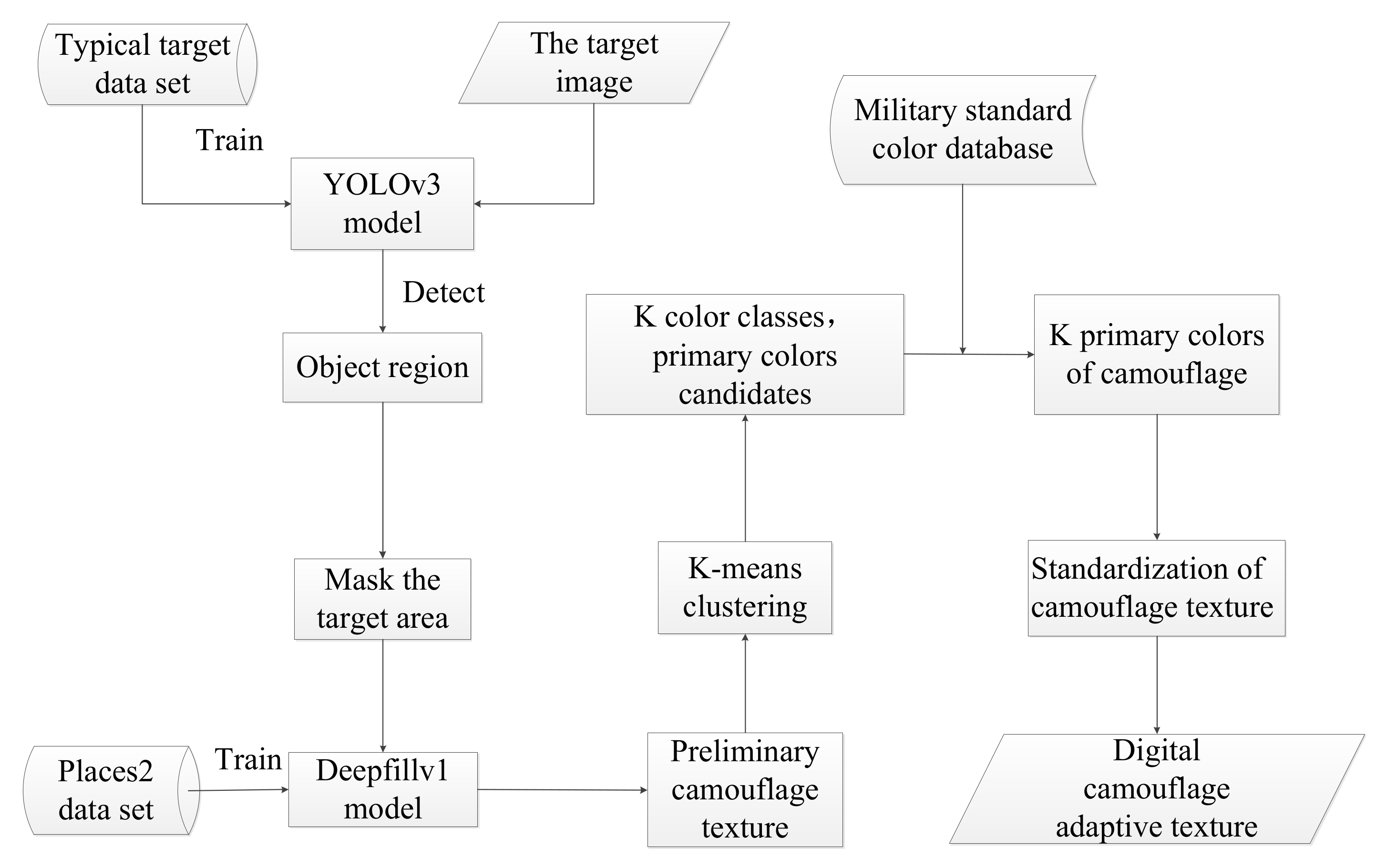
3.1. Outline of Proposed Method

The essence of optical camouflage is to make it impossible for human eyes or optical cameras to distinguish a target from its environment. This is similar to target removal in image processing. Inspired by this, we applied the image completion algorithm to the design of camouflage texture. In this paper, we provide a quick method based on the convolutional neural network to generate adaptive digital camouflage. The flowchart of our method is shown in Figure 1. To achieve camouflage of the target, we need to identify the target that needs camouflage. First of all, we used the YOLOv3 [38] algorithm to conduct recognition model training for four typical military targets. After adjusting the hyper parameters, we obtained a model with good recognition probability. Secondly, we masked the target area and entered it into the deepfillv1 [39] model that was pre-trained by places2 [40] for image completion. In this step, we obtain the preliminary camouflage texture. Thirdly, we used the k-means algorithm to calculate the main color of the filled area and compared it with the military standard color. The most similar color in the standard was selected as the main color, and the corresponding color was replaced. At this point, we have the final adaptive camouflage texture. The digital camouflage generated by this method is consistent with the texture of the surrounding environment. This method can generate visually plausible camouflage pattern structures and textures.

3.2. Dataset

In this paper, the Imagenet2012 [41] and Places2 [40] data sets were used. The Imagenet2012 [41] dataset consists of over 1.28 million images, containing 1000 categories, with the number of images per category ranging from 732 to 1300. Four typical military target images were selected from the ImageNet2012 [41]. This dataset was segmented into a training and test set. The four typical targets are airships, aircraft carriers, tanks, and uniformed soldiers. A total of 2187 images were selected from the dataset, of which 1970 were used for training and 217 for testing. There are no less than 500 pictures in each category. Table 1 shows the number of train and test images for the different categories. Figure 2 shows one sample for airships, aircraft carriers, tanks, and uniformed soldier images, which was selected from Imagenet2012.
The Place2 [35] dataset contains more than 400 different types of scene environments and 10 million images. Basically, covering people’s common scenes. Figure 3 shows one sample for forest, desert, grassland, and snowfield environment images, which was selected from Places2.

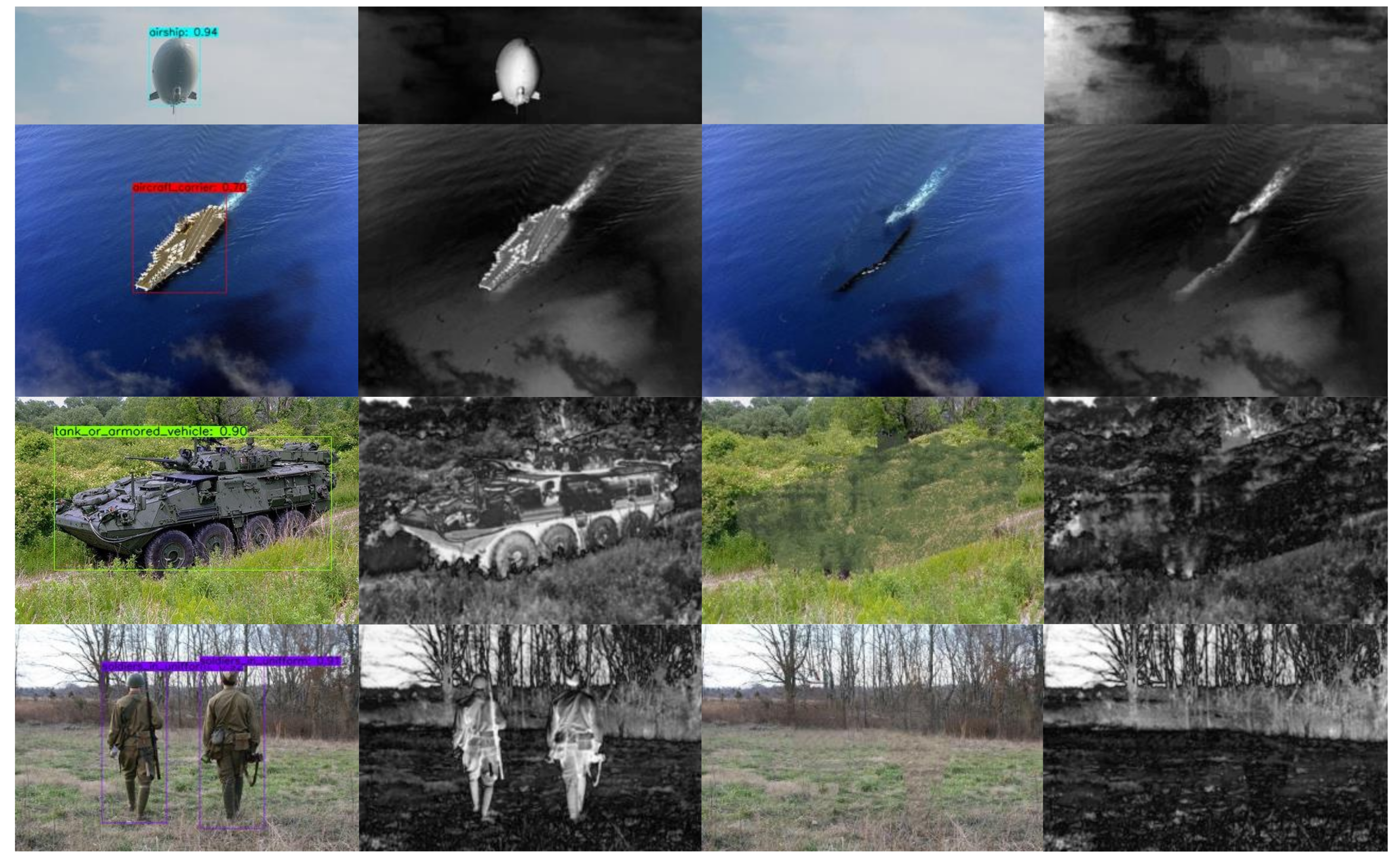
3.3. Military Target Detection Based on YOLOv3

To achieve camouflage of the target, we first needed to identify the target that needs camouflage. The YOLOv3 [38] algorithm was used to identify military targets. The Yolo series algorithm is an algorithm that could detect objects quickly [38,42,43]. The YOLOv3 is the latest version [38]. YOLOv3 can achieve high precision real-time detection, which is very suitable for our application background. Its network structure is shown in Figure 4. The resolution of the input picture in the network structure diagram is 416 × 416 × 3 (in fact, it can be any resolution.), and has four labeled classes. It uses darknet-53, which removes the full connection layer, as the backbone network. The YOLOv3 is a fully convoluted network that makes extensive use of residual network structures. As shown in Figure 4, YOLOv3 consists of DBL, resn, Up-sample, and concat. DBL stands for convolution (conv), batch normalization (BN) and leaky relu activation (Leaky reu). Resn represents the n residual units (res unit) in this residual block (res_block). Zero padding means using zero to fill the edge of the image. Up-sampling represents up-sampling. The concat represents the merging tensor. DBL*n represents the n DBL. The add represents the addition operation. The following y1, y2, and y3 represent feature maps with three different dimensions.
The network structure of darknet-53 is shown in Table 2. It uses successive 3 × 3 and 1 × 1 convolutional layers and some shortcut connections. The application of the shortcut connection layer allows the network to be deeper. It has 53 convolutional layers [38].
The loss function of YOLOv3 consists of localization loss L o s s l , confidence loss L o s s c , and classification loss L o s s p . The loss function is as follows:
L o s s = L o s s l + L o s s c + L o s s p
L o s s l = λ c o o r d i = 0 S 2 j = 0 B I i j o b j x i j x ^ i j 2 + y i j y ^ i j 2 + λ c o o r d i = 0 S 2 j = 0 B I i j o b j w i j w ^ i j 2 + h i j h ^ i j 2
L o s s c = i = 0 S 2 j = 0 B I i j o b j C ^ i j log C i j + 1 C ^ i j log 1 C i j + λ n o o b j i = 0 S 2 j = 0 B I i j n o o b j C ^ i j log C i j + 1 C ^ i j log 1 C i j
L o s s p = i = 0 S 2 I i j o b j c c a l s e s p ^ i j c log p i j c + 1 p ^ i j c log 1 p i j c
where λ c o o r d = 5 , I ij o b j = 1 when the j th boundary box in cell i is responsible for detecting the object, otherwise 0. x , y , w , h denotes the bounding box parameter, C i j is the box confidence score of the box j in cell i , λ n o o b j = 0.5 , I ij n o o b j is the complement of I ij o b j , p i j c denotes the conditional class probability of the box j th in cell i for class c . All the letters with superscript represent the corresponding ground truth (GT) values.
The learning rate adopts cosine attenuation:
α d e c a y e d = α e n d + 0.5 * ( α i n i t i a l α e n d ) * ( 1 + cos ( s g l o b a l / s t r a i n * p i ) )
where α d e c a y e d denotes the decayed learning rate; α i n i t i a l denotes the initial learning rate; α e n d denotes the end learning rate; s t r a i n denotes the total train steps; s g l o b a l denotes the global steps.
More details about YOlOv3 can be found in reference [38]. The basic code is online at https://github.com/YunYang1994/tensorflow-yolov3. Thanks to Yun Yang for sharing the code.

3.4. Preliminary Camouflage Texture Design Based on Deepfillv1

The essence of optical camouflage is to make it impossible for human eyes or optical cameras to distinguish a target from its environment. This is similar to target removal in image processing. Inspired by this, we applied the image completion algorithm to the design of camouflage texture. This method could be used to design the camouflage pattern consistent with the real-time background texture.
Deepfillv1 is a generated image inpainting model based on the contextual attention mechanism [39]. It can quickly generate a novel image structure consistent with the surrounding environment. The framework of deepfillv1 is shown in Figure 5. Deepfillv1 consists of two stages. The first stage is a simple dilated convolutional network trained with reconstruction loss to rough out the missing contents. The second stage is the training of the contextual attention layer. The core idea is to use the features of known image patches as the convolution kernel to process the generated patches to refine the fuzzy repair results. It is designed and implemented with convolution for matching generated patches with known contextual patches, channel-wise softmax to weigh relevant patches, and deconvolution to reconstruct the generated patches with contextual patches. The spatial propagation layer is used to improve the spatial consistency of the attention module. In order to make the network produce novel contents, another convolution path parallel to the contextual attention path is designed. The two paths are combined and fed to a single decoder for the final output. The entire network is trained end-to-end. The coarse network is trained explicitly with the reconstruction loss, while the refinement network is trained with the reconstruction, as well as global and local gradient penalty wasserstein GAN (WGAN-GP) [44,45] losses. The reconstruction loss uses a weighted sum of pixel-wise l 1 loss. The weight of each pixel is computed as γ l , where l is the distance of the pixel to the nearest known pixel. γ is set to 0.99. The WGAN-GP uses the Earth-Mover distance W P r , P g for comparing the generated and real data distributions. Its objective function is constructed by applying the Kantorovich–Rubinstein duality:
min G   max D E x ~ P r D x E x ˜ ~ P g D x ˜
where D is the set of 1-Lipschitz functions and P g is the model distribution implicitly defined by x ˜ = G z . z is the input to the generator.
The W P r , P g is as follows:
W P r , P g = inf γ P r , P g E x , y ~ γ x y
where P r , P g denotes the set of all joint distributions γ x , y whose marginals are P r and P g , respectively.
More details about deepfillv1 can be found in reference [39]. The basic code is online at https://github.com/JiahuiYu/generative_inpainting. Thanks to Jiahui Yu for sharing the code.

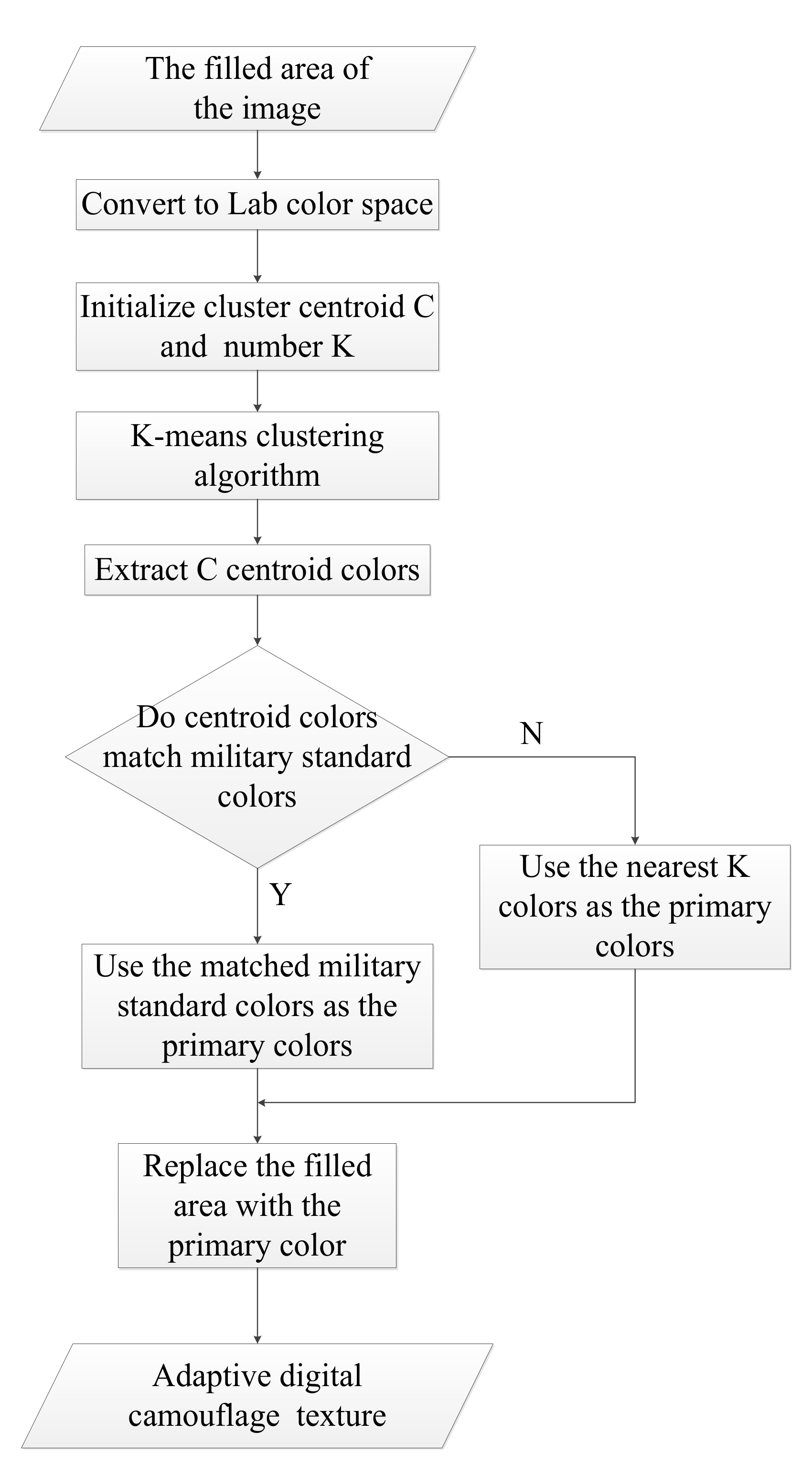
3.5. Standardization of Camouflage Texture based on K-means

The initial camouflage texture generated previously, although visually well integrated into the background, cannot be directly applied to the actual camouflage due to its large amount of colors. This is partly because it contains too many colors, which makes it difficult to operate in practical projects. On the other hand, the patterns generated by this method change with the environment, which leads to a huge increase in color further. Therefore, it is necessary to choose a limited number of colors as representative colors according to certain standards to replace similar colors, so as to achieve a balance between camouflage performance and engineering practice. We call this process the standardization of camouflage texture.
Based on the traditional digital camouflage color extraction method, we used the k-means clustering algorithm to extract the main color of the camouflage area. Note that extracting the primary color region here is different from the traditional method. We extract the preliminary camouflage designed area, while the traditional method is to extract the whole background. The flowchart of the extraction process of primary colors is shown in Figure 6. The extracted primary color also needs to meet the following restrictions [5]:
  • The primary colors should have different brightness so that the camouflage pattern could destroy the shape of the camouflaged target.
  • The primary colors should not be too different from the background colors.
The Red-green-blue (RGB), hue-saturation-value (HSV), and Lab color spaces are commonly used in image processing. The RGB color space is related to devices, it does not reflect the true nature of human vision. However, the Lab model is a device-independent color system and based on physiological characteristics. This means that it is a digital way to describe human vision. In this paper, we chose the Lab color space since it can mimic the human vision system more closely.
Figure 6 shows the standardization process for camouflage textures. Firstly, we converted the color space of the filled area from RGB space to Lab space. Secondly, we needed to initialize cluster centroid C and number K. Normally, C is set randomly, and K is set to 4 or 5. Thirdly, pixels in the filled area of the image were classified into different categories according to their distance from the clustering centroids. Then, the most representative color in each pixel category was selected as the representative color of each category. According to the geographical environment of the background, digital camouflage is usually divided into four types—woodland, desert, ocean, and urban camouflage. According to a large number of data and actual production experience, the standard primary colors of various digital camouflage are determined. In this study, after determining the representative colors of the target area, we selected the standard color, which is closest to the representative color as the primary colors for designing the target camouflage. Finally, we used the standard color to replace the color of the pixel in the filled area to obtain the self-adaptive digital camouflage texture.
We used the Euclidean distance to calculate the distance between the representative colors and the standard colors. The distance of one color pair d ( r , s ) is computed as:
d ( r , s ) = ( L r L s ) 2 + ( a r a s ) 2 + ( b r b s ) 2

4. Results

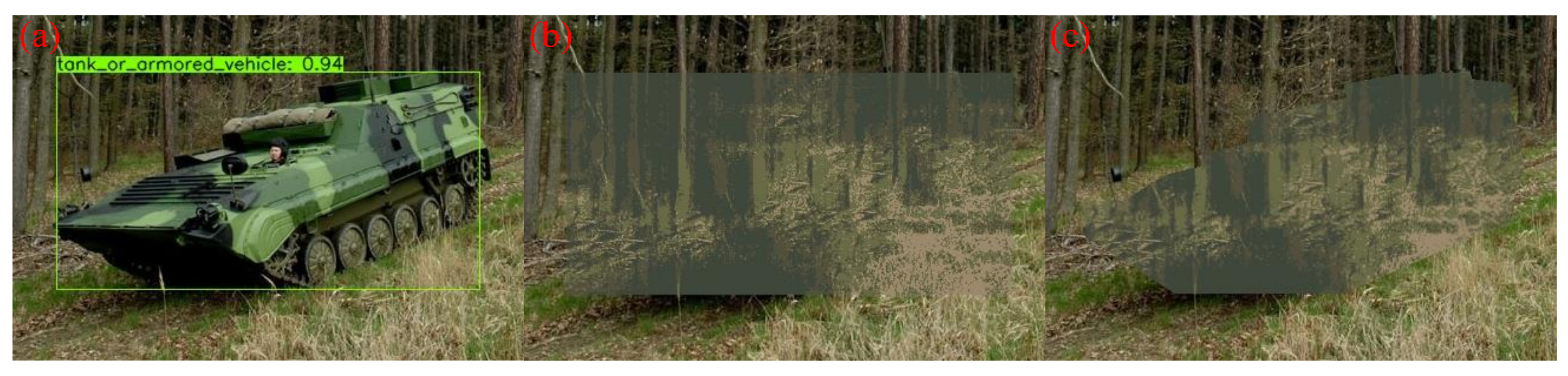
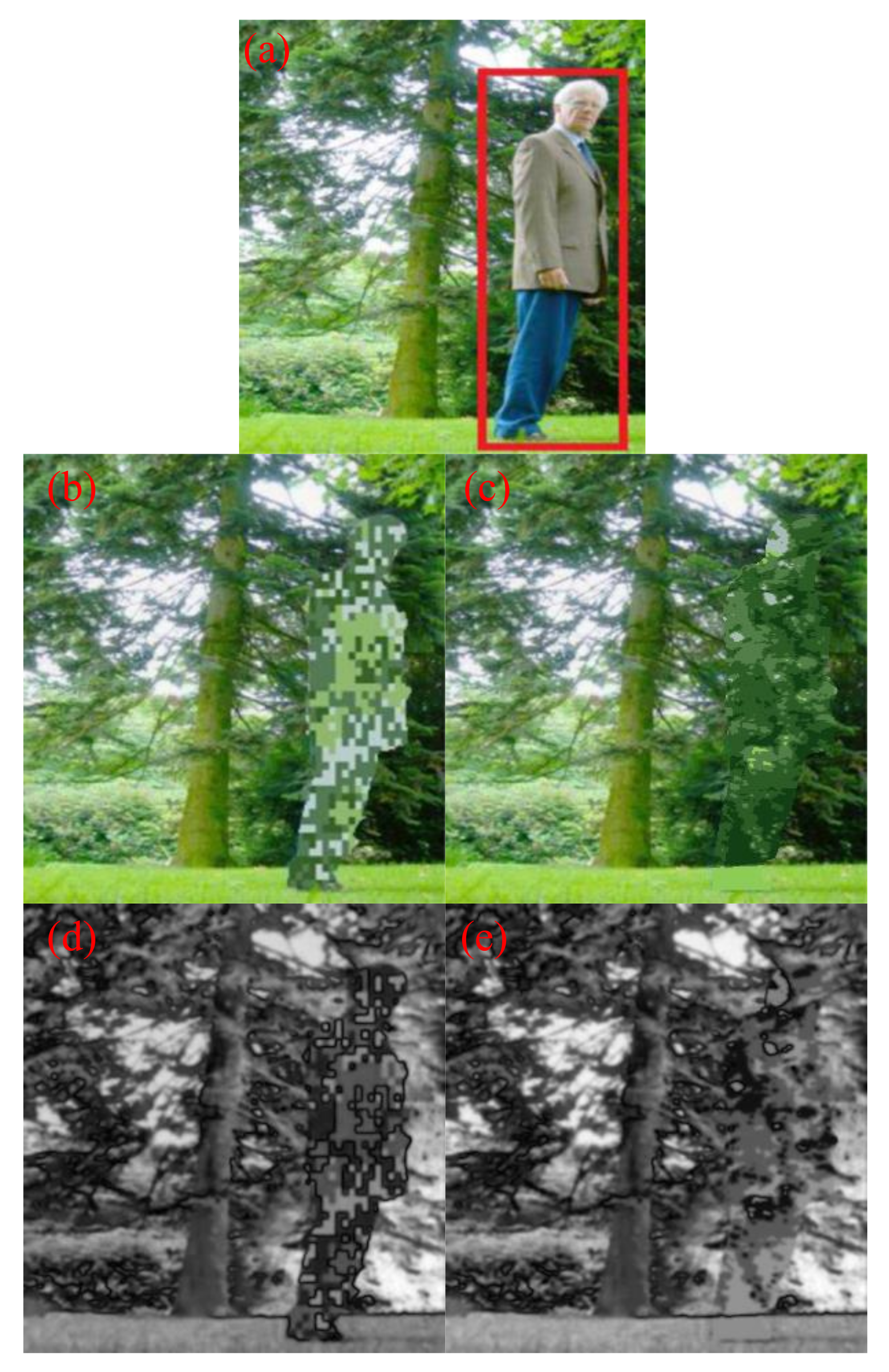
4.1. Military Target Detection

We used the method described in Section 3.3 to detect typical military targets. Four typical military target images were selected from the ImageNet2012 [41]. This dataset was segmented into a training and testing set. The four typical targets are airships, aircraft carriers, tanks, and uniformed soldiers. A total of 2187 images were selected from the dataset, of which 1970 were used for training and 217 for testing. There were no less than 500 pictures in each category. Unless otherwise noted, all the original images in this article about the four typical targets were from Imagenet2012.
The initial training parameters are shown in Table 3. I O U t h r e s h o l d is the intersection over union (IOU) threshold. We used multi-scale training methods.
We used k-means clustering to determine our nine bounding box priors. On the selected dataset, the nine clusters were: (55 × 69), (151 × 91), (84 × 261), (200 × 188), (331 × 137), (179 × 346), (358 × 223), (350 × 303), (373 × 387).
We used the pre-training weight on the coco data set as the initialization weight. After 17 k steps of training, the model converged. The training loss is shown in Figure 7. As shown in Figure 7a, after 17 k steps of training, the loss was reduced to 0.6, which is basically convergent. The mean average precision (mAP) at IOU = 0.5 ([email protected]) was 91.55%, as shown in Figure 7b. The results showed that the model we trained had high precision and could meet our application requirements. The total loss was calculated on the training set, and the mAP was calculated on the test set.
Through training, our recognition precision of these four typical targets in different environments reached 91.55% ([email protected]=91.55%), which highly met our application requirements. Moreover, this recognition process was just a demonstration. In practical applications, specific databases could be added according to the actual needs, and the recognition classes and precision could be increased through retraining (Figure 8). The recognition results of the model after our training are shown in Figure 8. As can be seen from Figure 8, our model could well identify four typical military targets. When the resolution of the input picture was 416 × 416, the model detection time was less than 25 ms.

4.2. Preliminary Camouflage Texture

We used the method described in Section 3.4 to design the initial camouflage texture. Firstly, we masked the target region detected by the YOLOv3, as shown in Figure 9b. Then, we input the masked image into the pre-train deepfillv1 model. The weights adopted by deepfillv1 were trained on the Place2 [40] data set. Places2 is a data set of scene images, containing 10 million pictures and more than 400 different types of scene environments, which could be used for visual cognitive tasks with the scenes and environments as application content, meeting our application requirements. We used the weight files from the literature [39] that were pre-trained on Place2 [40]. Finally, the complete image was obtained, which is called preliminary camouflage texture, as shown in Figure 9c. It could be seen from Figure 9 that the generated preliminary camouflage pattern had a texture consistent with the environment, which could be well integrated into the environment. When the input image resolution is 416 × 416, the preliminary camouflage texture generation process takes less than 0.2 s.
The more detailed experimental results are shown in Figure 10, where the first column shows the original images, with rectangular bounding boxes indicating the targets to be camouflaged, the second column shows the results of the preliminary camouflage texture design.

4.3. Standardization of Camouflage Texture

We standardized the initial camouflage texture using the method described in Section 3.5. As shown in Figure 11b, the camouflage texture we designed corresponded to the rectangular area where the target is located. Note that K is set to 5 when discussed later in this article. At the same time, we needed to design the camouflage texture for the camouflage target’s forward view, backward view, left view, right view, and top view, respectively. In practice, the texture of the camouflage area needed to be mapped to the actual target surface. This step could be accomplished with 3D rendering software, such as Maya or OpenGL, which is not described in this article as it focuses on the design approach. In this article, we simply mapped the camouflage texture to the camouflage target surface through a mask to observe its camouflage effect, as shown in Figure 11c. The output camouflage textures in Figure 11c had an overall optical camouflage effect, where textures and semantics were consistent with the environment look very naturally.
The more detailed experimental results are shown in Figure 12. The camouflage texture generation process in this paper is different from the traditional one. The traditional camouflage texture was obtained by random or non-random distribution using finite pattern templates or structural elements of texture. The camouflage texture generation in this paper is to use the method of image completion to generate the texture consistent with the current environment. The texture composition of this paper had no fixed structural elements. It might have been random for the natural environment like forest or regular for the artificial environment like the city, depending on the state of the current environment. The texture features come from a lot of training we did on the places2 [40] data set using the deepfillv1 [39] algorithm. The place2 [40] data set contains more than 400 different types of scene environments and 10 million images. Basically, it covers people’s common scenes. The deepfillv1 [39] algorithm, after training on places2 [40], was able to generate a meaningful image consistent with the background texture of the incomplete image. As shown in Figure 12, camouflage textures are designed using this method on both natural and artificial backgrounds. In Figure 12, the first column shows the original images in natural and artificial environments, and the second column shows the camouflaged image corresponding to the first column. The color of the second column camouflage texture was not replaced by the standard color. The third column shows the camouflaged image with the camouflaged texture of the standard color. In Figure 12, the first row shows the camouflage texture in the natural environment using our method, the second row shows the camouflage texture in the artificial environment using our method. As can be seen from Figure 12, the camouflage texture designed using the method we provided has an excellent camouflage effect in both natural and artificial environments. The camouflage texture in the natural environment is irregular, and the camouflage texture in the artificial environment has a certain rule, which is consistent with the current environment. Comparing Figure 12e,f, it is found that the camouflage performance decreased after filling the camouflage texture with the most similar standard color. This is because the standard colors we choose are only 30 colors specified in the standard, which is a little different from the main colors of the current environment. This does not affect the effectiveness of the design method we provide. With the development of controllable color change technology, we may be able to choose far more than 30 colors in the future. At that time, the camouflage performance of the camouflage texture designed by this method would be further improved.
When the input image resolution was 416 × 416, the standardization of the camouflage texture took 0.1 s. All the tests were implemented on Python3.6, TensorFlow v1.6, CUDNN v7.1, CUDA v9.2, and run on hardware with CPU Intel Core I7-9700F (3.0 GHz) and GPU RTX 2080 Ti. Meanwhile, the whole camouflage texture generation process took less than 0.4 s. This time could be shortened significantly with the improvement of the image completion algorithms or the improvement of hardware performance. We firmly believe that real-time methods will be proposed in the near future. This shows that the method provided in this paper could quickly generate camouflage texture in real-time, which could be used in future combat equipment and personnel adaptive camouflage design.

5. Discussion

Visual saliency is the perceptual quality that makes an object, person, or pixel stand out relative to its neighbors, and thus captures our attention. Therefore, it is a reasonable and effective method to evaluate the camouflage performance of a camouflaged target by the saliency detection algorithm, which has been used in many literatures [5,46,47]. In this paper, the frequency-tuned salient region detection (FT) [48] algorithm, as a classic saliency detection algorithm, was used to quantitatively evaluate the performance of camouflage texture. The saliency map of the camouflaged target was obtained after FT algorithm detection. The higher the salience value was, the more conspicuous was the foreground target, and the weaker was the camouflage effect.
To verify the validity and effectiveness of our proposed design method, we compared the saliency map of the camouflage texture designed using the traditional design method in the literature [5] with the camouflage texture designed using the method we provided, as shown in Figure 13. There are five images in Figure 13, where (a) shows an original image with foreground targets highlighted with red rectangles, (b) shows the results of camouflaging the targets using the camouflage texture designed by the existing method [5], (c) shows the results of manually camouflaging the targets using the camouflage texture designed by the method provided by us, (d) shows the saliency map corresponding to the image (b), (e) shows the saliency map corresponding to the image (c). As we can clearly see that the camouflage texture designed with our method has better camouflage performance, since in Figure 13d, the target contour and the mosaic-like stripe of the camouflage texture can be clearly distinguished, while in Figure 13e, the camouflage target could hardly be distinguished. Note that all images above have the same resolution. This difference is due to the camouflage texture designed by the method in literature [5] being inconsistent with the background texture and semantics, while the texture designed by the method we provide is consistent with the background texture and semantics. This is because we are able to learn features from the surrounding environment using the deepfillv1 algorithm, whereas the existing method is a texture template based on empirical design.
As shown in Figure 14, in order to evaluate the camouflage performance of the camouflage texture designed by our method, we used the saliency algorithm FT to calculate the salience map of the images before and after camouflage. In Figure 14, the first column shows the original image, the second column shows the salience map corresponding to the first column, the third column shows the camouflaged images using a texture designed by our method, the fourth column shows the salience map corresponding to the third column. As we can see from Figure 14, the designed camouflage texture satisfies the color condition: (1) the main color has different brightness, and (2) the main color is not much different from the background color. At the same time, the camouflage texture and the background have texture and semantic consistency. Therefore, the camouflage texture designed with the method we provided could blend well into the background.
In contrast with the original image, the foreground targets are almost indistinguishable in the camouflaged image’s salience map, suggesting that the camouflaged targets blend well into the background and are invisible to human eyes and visible light reconnaissance equipment. At the same time, we input the camouflaged image into the YOLOv3 model of the previous training for reidentification. The results show that the target in the camouflaged image cannot be recognized by the YOLOv3 model. The experimental results show that the adaptive digital camouflage with excellent camouflage performance could be designed quickly with our design method.

6. Conclusions

Adaptive optical camouflage technology is the inevitable direction of future optical camouflage technology development. As one of the key technologies of adaptive optical camouflage, the study of adaptive camouflage texture design has important theoretical and practical significance. In this paper, a fast-self-adaptive digital camouflage design method based on the neural network is proposed for the new generation of self-adaptive optical camouflage. First, we used the YOLOv3 algorithm to train the recognition model of four typical military targets. After adjusting the hyper-parameters, we got a model with good recognition probability, whose mean average precision (mAP) was 91.6%. Then, we used the deepfillv1 algorithm to do the preliminary camouflage texture design for the recognition area. Finally, the clustering algorithm was used to extract the main color of the camouflage target region, and the most similar color in the standard is used to standardize the color in the initial texture. The camouflage texture designed by our method was consistent with the texture and semantics of the real-time background. The whole texture generation process is very short, less than 0.4 s, which could meet the requirements of near-real-time camouflage design in the future. The saliency detection results showed that the camouflage texture generated by the proposed method had good camouflage performance in optical camouflage. At present, the method is effective for camouflage design in forest, grassland, desert, and other natural environments. But in artificial environment, such as urban environment, the effect of camouflage design is not very ideal. In addition, there are not many typical target images available and relevant datasets need to be further collected. In the future, on the one hand, we will further study how to improve the camouflage design performance of this method in an artificial environment. On the other hand, the implementation of adaptive camouflage systems will be further studied, such as the control system of adaptive camouflage. Nevertheless, this paper proposes and implements a new idea of adaptive camouflage texture design, which has important potential application value in future real-time optical camouflage.

Author Contributions

Conceptualization, H.X.; Data curation, H.X.; Formal analysis, H.X.; Investigation, Z.Q.; Methodology, H.X. Z.Q.; Project administration, M.L.; Supervision, M.L.; Visualization, Y.J., C.W. and R.Q.; Writing —original draft, H.X.; Writing—review & editing, Y.J. All authors have read and agreed to the published version of the manuscript.

Funding

This research received no external funding.

Conflicts of Interest

The authors declare no conflict of interest.

References

  1. Talas, L.; Baddeley, R.J.; Cuthill, I.C. Cultural evolution of military camouflage. Philos. Trans. R. Soc. Lond. B Biol. Sci. 2017, 372, 20160351. [Google Scholar] [CrossRef] [Green Version]
  2. Merilaita, S.; Scott-Samuel, N.E.; Cuthill, I.C. How camouflage works. Philos. Trans. R. Soc. Lond. B Biol. Sci. 2017, 372, 20160341. [Google Scholar] [CrossRef] [PubMed] [Green Version]
  3. King, A. The digital revolution: Camouflage in the twenty-first century. Millenn. J. Int. Stud. 2014, 42, 397–424. [Google Scholar] [CrossRef] [Green Version]
  4. Chu, M.; Tian, S.H. An Extraction Method for Digital Camouflage Texture Based on Human Visual Perception and Isoperimetric Theory. In Proceedings of the 2nd International Conference on Image, Vision and Computing, Chengdu, China, 2–4 June 2017; pp. 158–162. [Google Scholar]
  5. Xue, F.; Xu, S.; Luo, Y.T.; Jia, W. Design of digital camouflage by recursive overlapping of pattern templates. Neurocomputing 2016, 172, 262–270. [Google Scholar] [CrossRef]
  6. Zylinski, S.; Darmaillacq, A.S.; Shashar, N. Visual interpolation for contour completion by the European cuttlefish (Sepia officinalis) and its use in dynamic camouflage. Proc. R. Soc. B Biol. Sci. 2012, 279, 2386–2390. [Google Scholar] [CrossRef] [Green Version]
  7. Kelman, E.J.; Osorio, D.; Baddeley, R.J. A review of cuttlefish camouflage and object recognition and evidence for depth perception. J. Exp. Biol. 2008, 211, 1757–1763. [Google Scholar] [CrossRef] [Green Version]
  8. Barbosa, A.; Allen, J.J.; Mäthger, L.M.; Hanlon, R.T. Cuttlefish use visual cues to determine arm postures for camouflage. Proc. R. Soc. B Biol. Sci. 2012, 279, 84–90. [Google Scholar] [CrossRef]
  9. Allen, J.J.; Mäthger, L.M.; Barbosa, A.; Buresch, K.C.; Sogin, E.; Schwartz, J.; Chubb, C.; Hanlon, R.T. Cuttlefish dynamic camouflage: Responses to substrate choice and integration of multiple visual cues. Proc. Biol. Sci. 2010, 277, 1031–1039. [Google Scholar] [CrossRef] [Green Version]
  10. Teyssier, J.; Saenko, S.V.; Van Der Marel, D.; Milinkovitch, M.C. Photonic crystals cause active colour change in chameleons. Nat. Commun. 2015, 6, 1–7. [Google Scholar] [CrossRef] [Green Version]
  11. Vigneron, J.P.; Pasteels, J.M.; Windsor, D.M.; Vértesy, Z.; Rassart, M.; Seldrum, T.; Dumont, J.; Deparis, O.; Lousse, V.; Biro, L.P.; et al. Switchable reflector in the Panamanian tortoise beetle Charidotella egregia (Chrysomelidae: Cassidinae). Phys. Rev. E Stat. Nonlin. Soft Matter. Phys. 2007, 76, 031907. [Google Scholar] [CrossRef] [Green Version]
  12. Zhao, Y.; Xie, Z.; Gu, H.; Zhu, C.; Gu, Z. Bio-inspired variable structural color materials. Chem. Soc. Rev. 2012, 41, 3297–3317. [Google Scholar] [CrossRef] [PubMed]
  13. Morin, S.A.; Shepherd, R.F.; Kwok, S.W.; Stokes, A.A.; Nemiroski, A.; Whitesides, G.M. Camouflage and display for soft machines. Science 2012, 337, 828–832. [Google Scholar] [CrossRef] [PubMed] [Green Version]
  14. Wang, G.; Chen, X.; Liu, S.; Wong, C.; Chu, S. Mechanical Chameleon through Dynamic Real Time-Plasmonic Tuning. Acs Nano 2016, 10, 1788–1794. [Google Scholar] [CrossRef] [PubMed] [Green Version]
  15. Arsenault, A.C.; Míguez, H.; Kitaev, V.; Ozin, G.A.; Manners, I. Towards photonic ink (P-Ink): A polychrome, fast response metallopolymer gel photonic crystal device. Macromol. Symp. 2003, 196, 63–69. [Google Scholar] [CrossRef]
  16. Arsenault, A.C.; Puzzo, D.P.; Manners, I.; Ozin, G.A. Photonic-crystal full-colour displays. Nat. Photonics 2007, 1, 468–472. [Google Scholar] [CrossRef] [Green Version]
  17. Puzzo, D.P.; Arsenault, A.C.; Manners, I.; Ozin, G.A. Electroactive Inverse Opal: A Single Material for All Colors. Angew. Chem. Int. Edit. 2009, 48, 943–947. [Google Scholar] [CrossRef]
  18. Kim, H.; Ge, J.; Kim, J.; Choi, S.E.; Lee, H.; Lee, H.; Park, W.; Yin, Y.; Kwon, S. Structural colour printing using a magnetically tunable and lithographically fixable photonic crystal. Nat. Photonics 2009, 3, 534–540. [Google Scholar] [CrossRef]
  19. Yang, H.F.; Yin, J.P. An Adaptive Digital Camouflage Scheme Using Visual Perception and K-Mean Clustering. In Proceedings of the 3rd International Conference on Materials and Products Manufacturing Technology Guangzhou, Guangzhou, China, 25–26 September 2013; pp. 1091–1094. [Google Scholar]
  20. Simonyan, K.; Zisserman, A. Very deep convolution networks for large-scale image recognition. arXiv e-prints 2014, arXiv:1409.1556. [Google Scholar]
  21. Krizhevsky, A.; Sutskever, I.; Hinton, G.E. ImageNet classification with deep convolutional neural networks. Commun. ACM 2017, 60, 84–90. [Google Scholar] [CrossRef]
  22. Liu, Y.; Tao, Z.; Zhang, J.; Hao, H.; Peng, Y.; Hou, J.; Jiang, T. Deep-Learning-Based Active Hyperspectral Imaging Classification Method Illuminated by the Supercontinuum Laser. Appl. Sci. Basel 2020, 10, 17. [Google Scholar] [CrossRef]
  23. Girshick, R.; Donahue, J.; Darrell, T.; Malik, J. Rich feature hierarchies for accurate object detection and semantic segmentation. In Proceedings of the IEEE Conference on Computer Vision and Pattern Recognition, Columbus, OH, USA, 23–28 June 2014; pp. 580–587. [Google Scholar]
  24. Murthy, C.B.; Hashmi, M.F.; Bokde, N.D.; Geem, Z.W. Investigations of Object Detection in Images/Videos Using Various Deep Learning Techniques and Embedded Platforms-A Comprehensive Review. Appl. Sci. Basel 2020, 10, 46. [Google Scholar] [CrossRef]
  25. Prappacher, N.; Bullmann, M.; Bohn, G.; Deinzer, F.; Linke, A. Defect Detection on Rolling Element Surface Scans Using Neural Image Segmentation. Appl. Sci. Basel 2020, 10, 13. [Google Scholar] [CrossRef]
  26. Ronneberger, O.; Fischer, P.; Brox, T. U-Net: Convolutional Networks for Biomedical Image Segmentation. In Proceedings of the 18th International Conference on Medical Image Computing and Computer-Assisted Intervention, Munich, Germany, 5–9 October 2015; pp. 234–241. [Google Scholar]
  27. Long, J.; Shelhamer, E.; Darrell, T. Fully Convolutional Networks for Semantic Segmentation. In Proceedings of the IEEE Conference on Computer Vision and Pattern Recognition, Boston, MA, USA, 7–12 June 2015; pp. 3431–3440. [Google Scholar]
  28. Chen, L.C.; Papandreou, G.; Kokkinos, I.; Murphy, K.; Yuille, A.L. DeepLab: Semantic Image Segmentation with Deep Convolutional Nets, Atrous Convolution, and Fully Connected CRFs. IEEE Trans. Pattern Anal. Mach. Intell. 2018, 40, 834–848. [Google Scholar] [CrossRef] [PubMed]
  29. Iizuka, S.; Simo-Serra, E.; Ishikawa, H. Globally and locally consistent image completion. Acm T Graphic 2017, 36, 1–14. [Google Scholar] [CrossRef]
  30. Yu, J.; Lin, Z.; Yang, J.; Shen, X.; Lu, X.; Huang, T.S. Free-Form Image Inpainting with Gated Convolution. arXiv e-prints 2019, arXiv:1806.03589. [Google Scholar]
  31. Zhao, D.; Guo, B.L.; Yan, Y.Y. Parallel Image Completion with Edge and Color Map. Appl. Sci. Basel 2019, 9, 29. [Google Scholar] [CrossRef] [Green Version]
  32. Pezeshkian, N.; Neff, J.D. Adaptive electronic camouflage using texture synthesis. In Proceedings of the Conference on Unmanned Systems Technology XIV, Baltimore, MD, USA, 25–27 April 2012. [Google Scholar]
  33. Inami, M.; Kawakami, N.; Tachi, S. Optical camouflage using retro-reflective projection technology. In Proceedings of the 2nd IEEE/ACM International Symposium on Mixed and Augmented Reality, Tokyo, Japan, 7–10 October 2003; pp. 348–349. [Google Scholar]
  34. Uema, Y.; Koizumi, N.; Chang, S.W.; Minamizawa, K.; Sugimoto, M.; Inami, M. Optical Camouflage III: Auto-Stereoscopic and Multiple-View Display System using Retro-Reflective Projection Technology. In Proceedings of the 19th IEEE Virtual Reality Conference, Costa Mesa, CA, USA, 4–8 March 2012; pp. 57–58. [Google Scholar]
  35. Yu, C.; Li, Y.; Zhang, X.; Huang, X.; Malyarchuk, V.; Wang, S.; Shi, Y.; Gao, L.; Su, Y.; Zhang, Y.; et al. Adaptive optoelectronic camouflage systems with designs inspired by cephalopod skins. Proc. Natl. Acad. Sci. USA 2014, 111, 12998–13003. [Google Scholar] [CrossRef] [Green Version]
  36. Zhang, Y.; Xue, S.Q.; Jiang, X.J.; Mu, J.Y.; Yi, Y. The Spatial Color Mixing Model of Digital Camouflage Pattern. Def. Technol. 2013, 9, 157–161. [Google Scholar] [CrossRef] [Green Version]
  37. Jia, Q.; Xu, W.D.; Hu, J.H.; Liu, J.; Yang, X.; Zhu, L.Y. Design and evaluation of digital camouflage pattern by spot combination. Multimed. Tools Appl. 2020, 5, 18. [Google Scholar] [CrossRef]
  38. Redmon, J.; Farhadi, A. YOLOv3: An Incremental Improvement. arXiv e-prints 2018, arXiv:1804.02767. [Google Scholar]
  39. Yu, J.; Lin, Z.; Yang, J.; Shen, X.; Lu, X.; Huang, T.S. Generative Image Inpainting with Contextual Attention. arXiv e-prints 2018, arXiv:1801.07892. [Google Scholar]
  40. Zhou, B.; Lapedriza, A.; Khosla, A.; Oliva, A.; Torralba, A. Places: A 10 Million Image Database for Scene Recognition. IEEE Trans. Pattern Anal. Mach. Intell. 2018, 40, 1452–1464. [Google Scholar] [CrossRef] [PubMed] [Green Version]
  41. Deng, J.; Dong, W.; Socher, R.; Li, L.J.; Li, K.; Fei-Fei, L. ImageNet: A Large-Scale Hierarchical Image Database. In Proceedings of the IEEE-Computer-Society Conference on Computer Vision and Pattern Recognition Workshops, Miami, FL, USA, 20–25 June 2009; pp. 248–255. [Google Scholar]
  42. Deng, J.; Dong, W.; Socher, R.; Li, L.J.; Li, K.; Fei-Fei, L. You Only Look Once: Unified, Real-Time Object Detection. In Proceedings of the IEEE Conference on Computer Vision and Pattern Recognition, Seattle, WA, USA, 27–30 June 2016; pp. 779–788. [Google Scholar]
  43. Joseph, R.; Ali, F. Yolo9000: Better, faster, stronger. In Proceedings of the IEEE Conference on Computer Vision and Pattern Recognition, Honolulu, HI, USA, 21–26 July 2017; pp. 6517–6525. [Google Scholar]
  44. Arjovsky, M.; Chintala, S.; Bottou, L. Wasserstein GAN. arXiv e-prints 2017, arXiv:1701.07875. [Google Scholar]
  45. Gulrajani, I.; Ahmed, F.; Arjovsky, M.; Dumoulin, V.; Courville, A.C. Improved Training of Wasserstein GANs. arXiv e-prints 2017, arXiv:1704.00028. [Google Scholar]
  46. Feng, X.; Guoying, C.; Richang, H.; Jing, G. Camouflage texture evaluation using a saliency map. Multimed. Syst. 2015, 21, 169–175. [Google Scholar] [CrossRef]
  47. Cheng, X.P.; Zhao, D.P.; Yu, Z.J.; Zhang, J.H.; Bian, J.T.; Yu, D.B. Effectiveness evaluation of infrared camouflage using image saliency. Infrared. Phys. Technol. 2018, 95, 213–221. [Google Scholar] [CrossRef]
  48. Achanta, R.; Hemami, S.; Estrada, F.; Susstrunk, S. Frequency-tuned Salient Region Detection. In Proceedings of the IEEE-Computer-Society Conference on Computer Vision and Pattern Recognition Workshops, Miami, FL, USA, 20–25 June 2009; pp. 1597–1604. [Google Scholar]
Figure 1. Outline of proposed digital camouflage design method.
Applsci 10 05284 g001
Figure 2. Data samples from the Imagenet2012 dataset. (a) airship; (b) aircraft carrier; (c) tank; (d) uniformed soldier.
Applsci 10 05284 g002
Figure 3. Data samples from the Places2 dataset. (a) forest; (b) desert; (c) grassland; (d) snowfield.
Applsci 10 05284 g003
Figure 4. YOLOv3 network structure.
Applsci 10 05284 g004
Figure 5. The framework of deepfillv1.
Applsci 10 05284 g005
Figure 6. Standardization of camouflage texture4 results.
Applsci 10 05284 g006
Figure 7. The total training loss and mean average precision. (a) the total loss; (b) the mAP.
Applsci 10 05284 g007
Figure 8. Object detection results. (a) airship; (b) aircraft carrier; (c) tank; (d) uniformed soldier.
Applsci 10 05284 g008
Figure 9. Preliminary camouflage texture design. (a) original image; (b) masked image; (c) completed image.
Applsci 10 05284 g009
Figure 10. More detailed experimental results. (a) airship; (b) preliminary camouflage texture of the airship; (c) aircraft carrier; (d) preliminary camouflage texture of the aircraft carrier; (e) tank; (f) preliminary camouflage texture of the tank; (g) uniformed soldiers; (h) preliminary camouflage texture of the uniformed soldiers.
Applsci 10 05284 g010
Figure 11. Adaptive digital camouflage texture. (a) Original image; (b) Rectangular texture area; (c) Camouflaged images using textures.
Applsci 10 05284 g011
Figure 12. Camouflage textures in natural and artificial environments. (a) the original image in natural environment; (b) the camouflaged image corresponding to (a) whose color wasn’t replaced by standard color; (c) the camouflaged image corresponding to (a) whose color was replaced by standard color; (d) the original image in artificial environment; (e) the camouflaged image corresponding to (d) whose color wasn’t replaced by standard color; (f) the camouflaged image corresponding to (d) whose color was replaced by standard color.
Applsci 10 05284 g012
Figure 13. Comparison between our method and an existing method. (a) original image; (b) traditional camouflage texture; (c) adaptive camouflage texture; (d) the saliency map corresponding to image (b); (e) the saliency map corresponding to image (c).
Applsci 10 05284 g013
Figure 14. Evaluate the performance of the camouflage image using the salience map.
Applsci 10 05284 g014
Table 1. Details of the training and test set.
CategoryTraining SetTest Set
Airships45950
Aircraft Carriers45550
Tanks49655
Uniformed Soldiers56062
Total1970217
Table 2. Darknet-53 [38].
TypeFiltersSize/StrideOutput
Convolutional323 × 3416 × 416
Convolutional643 × 3/2208 × 208
Convolutional321 × 1
Convolutional643 × 3
Residual 208 × 208
Convolutional1283 × 3/2104 × 104
Convolutional641 × 1
Convolutional1283 × 3
Residual 104 × 104
Convolutional2563 × 3/252 × 52
Convolutional1281 × 1
Convolutional2563 × 3
Residual 52 × 52
Convolutional5123 × 3/226 × 26
Convolutional2561 × 1
Convolutional5123 × 3
Residual 26 × 26
Convolutional10243 × 3/213 × 13
Convolutional5121 × 1
Convolutional10243 × 3
Residual 13 × 13
Avgpool Global
Connected 1000
Softmax
Table 3. The training parameters.
VariableValueVariableValue
I O U t h r e s h o l d 0.5 α i n i t i a l 1 α 10−4
Batch_size6 α e n d 1 α 10−6
Input_size[320, 352, 384, 416, 448, 480, 512, 544, 576, 608] α t r a i n

