Abstract
In wireless communication systems, reliability, low latency and power are essential in large scale multi-hop environment. Multi-hop based cooperative communication is an efficient way to achieve goals of wireless networks. This paper proposes a relay selection scheme for reliable transmission by selecting an optimal relay. The proposed scheme uses a signal-to-noise ratio (SNR) based Q-learning relay selection scheme to select an optimal relay in multi-hop transmission. Q-learning consists of an agent, environment, state, action and reward. When the learning is converged, the agent learns the optimal policy which is a rule of the actions that maximize the reward. In other words, the base station (BS) knows the optimal relay to select and transmit the signal. At this time, the cooperative communication scheme used in this paper is a decode-and-forward (DF) scheme in orthogonal frequency division multiplexing (OFDM) system. The Q-learning in the proposed scheme defines an environment to maximize a reward which is defined as SNR. After the learning process, the proposed scheme finds an optimal policy. Furthermore, this paper defines a reward which is based on the SNR. The simulation results show that the proposed scheme has the same bit error rate (BER) performance as the conventional relay selection scheme. However, this paper proposes an advantage of selecting fewer relays than conventional scheme when the target BER is satisfied. This can reduce the latency and the waste of resources. Therefore, the performance of the multi-hop transmission in wireless networks is enhanced.
1. Introduction
Recently, wireless communication systems have achieved a high data rate and high bandwidth efficiency by using multiple antennas at the transmitter and receiver. In addition, as 5G becomes commercially available, the demand for narrowband systems is increased. The main idea of narrowband transmission is a robustness for the frequency selectivity of wireless fading. To solve this problem, the multi-hop transmission can be considered as a distributed multiple-input and multiple-output (MIMO) array. Moreover, it shows that transmit diversity can be achieved by a time division based decode-and-forward (DF) protocol. Thus, reliability is improved.
However, the MIMO system has disadvantages if there are constraints on the size or cost of the user equipment (UE). To solve these problems, the cooperative communication scheme has emerged. The cooperative communication scheme can be regarded as a virtual MIMO system by utilizing the relay. The cooperative communication scheme is generally divided into two schemes. The first one is amplify-and-forward (AF) method and it amplifies a signal in relay and transmits the signal to the destination. The other one is DF which demodulates and modulates the source signal in the relay and then transmits it to the destination. However, if many relays exist in the cooperative communication, the use of all the relays wastes unnecessary resources. Failure to select the appropriate relay can degrade the performance of the entire system. Therefore, an appropriate relay should be selected.
Figure 1 shows the multi-hop wireless networks. In general, there are many nodes that exist in the process of transmitting signals. In this process, the use of relay sends a signal efficiently. However, too many relays can cause the unexpected effect. In [1], when more relays exist, the performance is mitigated due to the overhead. This paper proposes a method that achieves the same performance and throughput using fewer relays, and the relay selection scheme is very important. Therefore, the proposed scheme selects a better relay with the same performance.
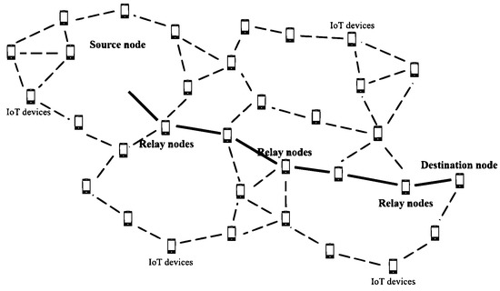
Figure 1.
The system model for multi-hop wireless network.
Relay selection techniques vary with criteria that the relay is selected. Best harmonic mean (BHM) is a well-known basic relay selection scheme [1]. In addition, Yu used a superposition modulation in cooperative communication and Wu used a power allocation for relay selection [2,3]. Furthermore, Kim used a novel dirty paper coding (DPC) and singular value decomposition (SVD) in multi-hop transmission of multi-user MIMO (MU-MIMO) system [4]. Recently, the relay selection for non-orthogonal multiple access (NOMA) is applied and 5G also uses a relay selection [5,6].
The BHM scheme is known as an optimal relay selection scheme. BHM scheme uses a channel state information (CSI) between source-relay-destination nodes to obtain a harmonic mean of channel coefficient. This CSI is feedbacked to the source node and the source finds an optimal relay. However, the BHM scheme causes latency and waste of resources to find an optimal relay and the number of relays is increased in this process to earn an optimal performance. Furthermore, the throughput is severely decreased since the routing with four or more hops increases forwarding delay and it causes many overheads and signal processing delay for overall systems [7]. In [8], an optimal relay selection scheme using the reinforcement learning was proposed by analyzing secrecy outage in multi-hop systems. The authors in [8] proposed partial relay selection schemes for reducing the system complexity and power consumption. The proposed relay selection scheme solves one of main issues in the relay selection where the required instantaneous channel state information is reduced, and it can be easily implemented in the complex network such as ad-hoc and mesh networks. The total data rate in multi-hop systems which use half-duplex relay is decreased as the number of hops is increased. However, the existing study in [8] did not consider the number of selected hops, and it causes serious decrease in maximum data rate which is one of very important performance indicators in mobile communication systems. For solving the drawbacks of the existing study efficiently, the proposed scheme selects the number of minimum relays for obtaining target error performance. Generally, the error performance is improved when the number of used relays is increased since an effect of fading channel and error propagations are decreased (but total data rate is decreased). For better understanding, let the number of minimum relays for obtaining target error performance be N. When the system selects the number of relays which is larger than N such as or , the total data rate is decreased. On the other hand, when the system selects the number of relays which is less than N such as or , the system does not obtain target error performance. Therefore, the main drawbacks for the existing study is solved by our proposed scheme and the proposed scheme can be used more practically since the loss of total data rate is less than the existing study in [8].
So, the number of relays must be reduced to solve this problem. Therefore, this paper proposes a scheme with fewer relays and the same BER performance compared to the conventional BHM scheme.
This paper uses a Q-learning based relay selection scheme to select an optimal relay and reduce the latency in multi-hop wireless networks. Nowadays, there are many relay selection schemes using reinforcement learning in cooperative networks [9,10,11,12,13]. These papers are focused on using reinforcement learning to improve performance through selected relays. However, the purpose of this paper is to reduce the latency that occurs in the process of passing the relay with the same performance. The proposed scheme has a low latency and same reliability compared to the conventional BHM scheme. This paper is organized as follows.
2. System Model and Conventional Selection Schemes
Figure 2 shows the multi-hop system model. The S and D represent a source and destination respectively. The means the m-th relay among the total K relays. The , , and represent a channel coefficient of the source-destination, source-relay, relay-destination and relay-relay node. The total number of nodes including source and destination is . The distance between the source and destination node is normalized to 1. The distance between relays is also normalized randomly from zero to 1. However, if the signal goes through a random relay between source and destination, the total sum of the distance between source-relay and relay-destination is greater than 1 and it causes a signal deterioration. So, if the relay is not located on the line-of-sight (LoS), the distance is longer. This deterioration should be reduced as much as possible. Therefore, the goal is to select the most suitable relay among random relays through the Q-Learning in this paper. The signal transmission scheme uses a DF scheme in the OFDM system.
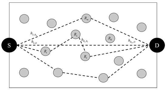
Figure 2.
Multi-hop system model.
2.1. Random Relay Selection Scheme
The random relay selection scheme selects a relay among several relays randomly. In other words, the random relay selection scheme selects a relay without considering the signal-to-noise ratio (SNR) of the received signal and a channel condition of the source, relay and destination. Therefore, the random relay selection scheme is very simple. However, it may select a relay having a bad channel condition and degrade the performance of the cooperative communication system.
2.2. Threshold-Based Relay Selection Scheme
The threshold-based relay selection scheme is one of the sub-optimal relay selection schemes. This scheme determines the threshold in order to select the relay. The threshold depends on how to define the threshold value [3]. There are many methods for these thresholds. The average SNR of the received signal or the average of the channel magnitude of the source and relay are frequently used as the threshold. The threshold-based relay selection scheme selects the relay that has higher value than the threshold. The average of the channel magnitude method in this paper is as follows,
where the K is a total relay index and the is a channel magnitude. The cooperative communication is performed through the selected relay (). In the threshold-based relay selection scheme, the performance of the cooperative communication is degraded since the threshold only considers the source-relay channel, not all CSI. However, since only channel information between the source and relay is needed, this scheme has a low-complexity.
2.3. Best Harmonic Mean Scheme
The last relay selection scheme is a best harmonic mean scheme. The BHM relay selection scheme is generally known as one of the optimal relay selection schemes. The CSI is necessary in order to calculate the harmonic mean of all relays. In summary, the source should obtain the harmonic mean of two channels by using the CSI. This scheme uses a magnitude of two channels between source-relay and relay-destination. The m-th harmonic mean is calculated as follows,
where the k means the sub-carrier index. The means the channel magnitude between the source and the m-th relay. The means the channel magnitude between the m-th relay and the destination. The source compares with each harmonic mean and selects the relay that has the largest harmonic mean. Since the BHM scheme is an optimal relay selection scheme, it provides very high reliability. However, since the source needs to know all the channel information, it is difficult to use in a practical system.
3. Proposed Relay Selection Scheme
3.1. Q-Learning Theory
Reinforcement learning (RL) is defined as a machine learning scheme that is concerned how software agents should take actions in an environment. The purpose of the RL is to maximize the cumulative rewards. The machine learning can be divided into three types. Supervised learning means learning getting the right answer and getting feedback immediately. Unsupervised learning is a solving problem like classification with no correct answer. RL does not know the correct answer, but it learns from trial and error since agent knows the reward of its action. When information about the environment does not exist, it acts randomly. However, as learning progresses, more regular actions are repeated and can find a goal.
RL has several schemes such as state-action-reward-state-action (SARSA), Q-learning, deep Q-network (DQN), deep deterministic policy gradient (DDPG) and asynchronous advantage actor-critic algorithm (A3C). Among them, the Q-learning scheme is the most widely known algorithm.
When the learning is completed, the destination learns the optimal policy which is a rule of the actions that maximizes the reward. In other words, the purpose of the Q-learning is to find an optimal policy. Q-learning is a suitable algorithm for unknown environment and can be used in future wireless cooperative communication where the environments are changed rapidly. Figure 3 shows the Q-learning agent-environment model. Agent takes action in environment and receives the feedbacks from the environment to find an optimal policy and the Q-function is also part of the agent. In the feedback process, an immediate reward is defined as . A reward for the future situation caused by present action is received by using Q-value (). The purpose of the Q-learning takes an action that can update the Q-table consisting of Q-values and maximize the reward from environment [14]. The formula of the Q-function is as follows,
where the denotes the next state when it takes an action a in the current state s. The means action that can be taken in next state . Furthermore, the is a discount factor which is the weight of the current and future reward. The is a learning rate which indicates whether the learning depends on the current or future learning information. As the learning is progressed, the Q-value is updated at each iteration and is stored in a Q-table. Table 1 shows the Q-table of Q-learning algorithm.
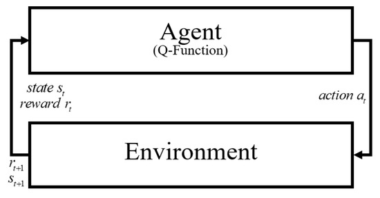
Figure 3.
Q-learning agent-environment model.

Table 1.
The Q-table in Q-learning algorithm.
Table 1 represents the situation where the N actions exist. First, the Q-table is initialized to zero and the Q-values are stored as time goes by. Therefore, optimal actions in given environment are founded through the learning in Q-learning algorithm. Furthermore, this paper uses the decaying-greedy algorithm for exploration and exploitation in order to choose the optimal action. In the generally known Q-learning algorithm, the destination selects an action by exploration and exploitation [15]. Exploration takes a random action to achieve more knowledge of the reward and the exploitation selects the best possible action based on the current knowledge of rewards. The action in this situation is as follows,
where the p denotes a random variable at the action in time t and the denotes a probability that a random action is chosen. At this point, when learning is completed to a certain extent, epsilon is lowered because it does not need to find another path on purpose. The initial value of epsilon is not determined. This value can be arbitrarily specified in the environment design and is decreased according to the learning process. The process of changing the epsilon value also depends on the learning environment and circumstances. So, it is usually adjusted to a fine value for learning accuracy. In Q-Learning, the epsilon value decreases by the specified number when the goal is reached and the number is applied to the next learning. Ultimately, when the epsilon value approaches zero, learning proceeds in the desired direction. Therefore, at each iteration of the learning process, the agent either chooses random or an action. The selected actions become policy and with repeated actions, the optimal policy can be found.
3.2. Proposed Relay Selection Scheme
Figure 4 shows the agent-environment for Q-learning in the proposed scheme. First, when the agent takes an action in current state, the environment updates the information about the next state and next reward to the current state and current reward. Next, depending on the reward which is defined in this paper, the Q-value is updated according to the Q-function and updated values are stored in the Q-table. Finally, the highest value among the updated Q-values can be found when the learning is completed and the relay which has the highest Q-value is selected as an optimal relay. If the learning process is briefly described, action is randomly performed and Q-value is stored one by one. When this process is repeated through the learning, various Q-values are stored in the Q-table. When the learning is completed, the highest state among those values is selected as an optimal state and this state represents an optimal relay [15].
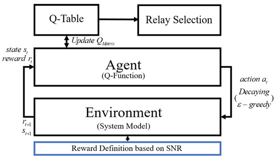
Figure 4.
Proposed agent-environment system model.
The proposed scheme uses a SNR based Q-learning algorithm to select an optimal relay for cooperative communication. In this paper, the states, actions and a reward are defined for proposed relay selection scheme. First, the proposed scheme for relay selection in cooperative communication has total N nodes. This paper defines states as where i denotes an index of the node for cooperative communication. Second, an action a means the selection of a relay from available K relays and is defined as . As a result, the action is changed from a current state to next state. Such action may improve or degrade the performance. Optimal action is naturally learned when appropriate rewards are given. Third, the Q-table is composed with Q-values for each state and action. Initially, the Q-table elements are set to zero. When the learning starts, the agent chooses an action and observes the state to update the Q-table. The Q-matrix defined in this paper is as follows, The Q-value is updated after the learning according to the reward. Reinforcement learning is conducted through random action, so before learning, Q-matrix does not know the included Q-value. So, the definition of a reward is important. The reward is defined by mutual information in terms of the information theory [8]. However, the maximum mutual information is the same as capacity and the capacity depends on SNR and bandwidth. Since bandwidth is normalized, only SNR is considered for the reward. To set a reward value, the size of the channel coefficient between source-relay-destination node is compared and then the SNR is obtained based on the these values and set as a reward value. The reward defined in this paper is as follows,
where the reward R is defined as a SNR of the source, relay and destination at state and action . This paper sets the reward function by obtaining SNR that can perform an accurate comparison while annalistic complexity is reduced. Equation (7) is a generalized representation of all SNR values between source-relay-destination. A high Q-value is obtained and stored in Q-matrix in state if the Q-value in state is greater than the Q-value in state . Finally, when the Q-table is updated, the Q-learning finds the optimal policy by selecting the state that has the highest reward. The reward matrix defined in this paper is as follows,
In this environment, the reward is initialized to zero when the learning process returns to the source node. The reward matrix is a collection of the reward values of all source-relay-destination for optimal Q-value calculation. The size and value of the reward matrix are determined according to the reward. In addition, since relay is used in cooperative communication, there is no line-of-sight (LOS) signal and the SNR value between source and destination node is also initialized to zero. Furthermore, when the learning process is finished at the destination node, the next episode begins and the reward is also reset to zero. Reward is defined on the basis of SNR and the relay is selected through the learning process.
The greatest benefit of the proposed SNR based Q-learning scheme is less exchange of CSI and the optimal relay can be selected through the self-learning. Furthermore, it reduces the latency and the waste of resources when the target BER is satisfied. Therefore, it can mitigate the overhead occurred in a cooperative communication without exchanging the information and also can reduce the latency compared to the conventional BHM scheme.
4. Simulation Results
Table 2 shows the simulation parameters. The modulation scheme is QPSK and the number of sub-carriers is 128. The length of the cyclic prefix (CP) is 32 and distance between source and destination is normalized to 1. The channel is 7-path Rayleigh fading channel and total transmit power is normalized to 1. The number of the relays is 9. Distance between relay-to-relay is randomly distributed from zero to 1. In Q-learning, the discount factor and the learning rate are 0.8 and the initial Epsilon of 0.9 decays gradually. These parameters may vary depending on the learning environment, state and action. The numerical values presented in this paper are determined for finding the optimal Q-value. These parameters were determined through the several learning processes in this paper. These parameters are not set. So, if the parameter is set incorrectly, it may not have the optimal value. Therefore, the simulation is performed based on the value that obtains the best performance among the multiple learning results and this paper used these values.
Table 2.
Simulation parameters.
The Figure 5 shows the BER performance of the conventional and proposed relay selection scheme. It is shown that the proposed scheme has the same BER performance with the conventional BHM scheme which is known as the optimal relay selection scheme. Since the random relay selection selects the relay randomly, it has the lowest BER performance. The threshold-based relay selection scheme has better performance than the random relay selection because it uses relays that exceed the threshold to select the relays. Since the BHM scheme selects the relay that has the largest harmonic mean, the performance is best. The proposed relay selection scheme shows the same BER performance with BHM which is known as the optimal relay selection scheme. In addition, the conventional BHM scheme requires all channel information for relay selection. Thus, the conventional scheme cannot be used in a practical system. However, the proposed scheme does not need all the channel information and it can reduce the latency. So, the overhead and waste of resources are lower than the conventional BHM scheme. Therefore, the proposed scheme has the same performance with the conventional BHM scheme but it has a fewer number of relays.
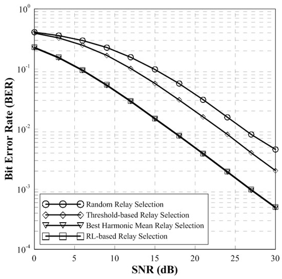
Figure 5.
BER performance of conventional schemes and proposed scheme (two-hop).
Figure 6 shows the throughput of conventional and proposed scheme. It can be seen that the throughput of the random relay selection and the threshold-based relay selection is low. However, the throughput of the RL-based relay selection scheme is the same as that of the BHM scheme. Therefore, the proposed scheme can achieve the same throughput performance with the BHM scheme known as an optimal relay selection scheme.
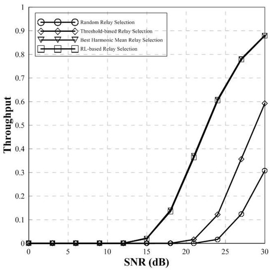
Figure 6.
Throughput of conventional scheme and proposed scheme (two-hop).
Figure 7 and Figure 8 show the BER performance and throughput of conventional BHM and proposed relay selection scheme in multi-hop environment. In general, a large number of relays can degrade the performance due to the error propagation and interference between relays. However, if the source-destination node is normalized, the performance is improved since the degradation can be reduced through modulation and demodulation of the transmit signal.
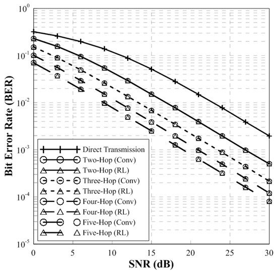
Figure 7.
BER Performance of BHM and RL-based scheme (multi-hops).
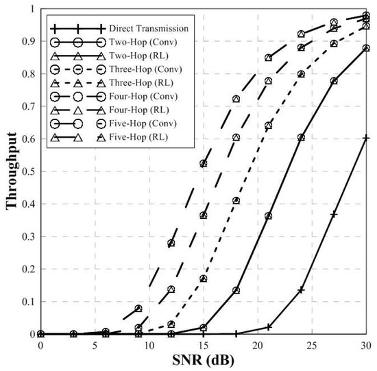
Figure 8.
Throughput of conventional scheme and proposed scheme (multi-hop).
In Figure 7, the performance of the conventional BHM and proposed RL-based relay selection scheme is same. Since the distance between source and destination node is normalized to 1, the BER performance of multi-hops is better than the direct transmission. Furthermore, according to increase of the number of relays, the BER performance is improved.
Figure 8 shows the throughput of conventional and proposed scheme in multi-hop environment. The throughput performance of BHM scheme and the proposed relay selection scheme is the same. In addition, according to the increase of the number of relays, the higher throughput performance can be obtained. Furthermore, as the number of hops increases, the throughput performance converges to 1. Therefore, the proposed scheme has same throughput performance compared to the conventional BHM scheme.
Figure 9 indicates the number of selected hops of the conventional and proposed scheme. The training iteration used in this simulation is 500 times. When learning is performed 500 times in an environment that satisfies the target BER, this graph shows the number of hops used in conventional and proposed scheme. When the target BER is satisfied, the conventional BHM scheme has a large number of hops compared to the proposed scheme. The proposed scheme selects fewer relays than the conventional scheme. The RL-based scheme has 3 more hops than conventional scheme and the conventional scheme has 4 and 5 more hops than the RL-based scheme. Therefore, the proposed scheme has the same performance but has fewer number of relays than the conventional scheme.
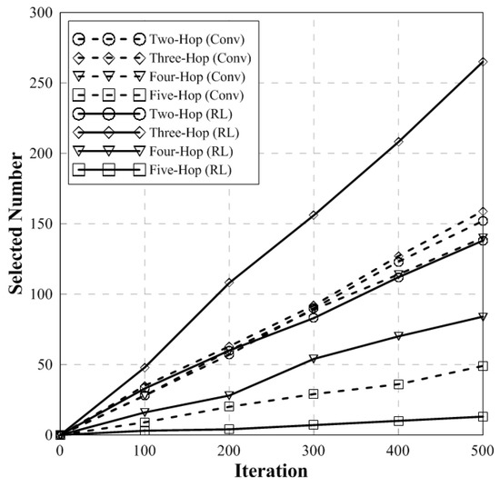
Figure 9.
The number of selected hops.
Figure 10 shows the average number of selected hops of the conventional and proposed scheme. In 3 hops, average selected number of relays in proposed scheme is high compared to the conventional BHM scheme. However in 4 and 5 hops, average selected number of relays in proposed scheme is fewer than the conventional scheme. This indicates that, when the target BER is satisfied, the benefit of the latency or waste of resources can be achieved through fewer selected relays.
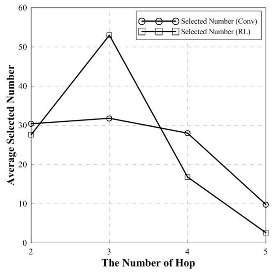
Figure 10.
The number of average selected hops.
Figure 11 shows the number of steps in proposed RL-based scheme according to the learning episode when the target BER is satisfied. In this figure, a step represents how many relays are passed until it reaches the destination node. In the early stage of the learning process, it is shown that the number of steps is very high. However, as the learning progresses, the number of hops is decreased. Finally, after 400,000 episodes, the number of steps converges to 3. This shows that three relays have the best performance when the target BER is satisfied.
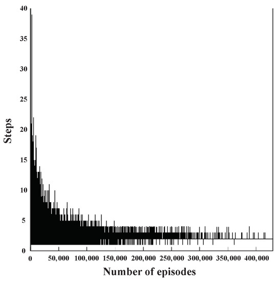
Figure 11.
The number of steps in proposed scheme according to the learning episode.
5. Conclusions
In wireless networks, multi-hop communication system becomes an important issue. In this situation, it is important to select an appropriate relay for signal transmission in multi-hop environment. If the proper relay is not selected, it may cause performance degradation of the device node and additional damage such as an error propagation, latency and waste of resources. So, the proposed scheme can achieve the same performance with the conventional BHM scheme and satisfy the target BER while reducing the number of hops. In the proposed scheme, the optimal relay is selected which maximizes the reward based on SNR by using Q-learning algorithm in the multi-hop system. This paper proposes a method to define the received SNR at each node as a reward. The simulation results show that the proposed scheme has same BER performance and throughput but fewer relays than the conventional BHM scheme when the target BER is satisfied. This reduces the latency and the waste of resources. Therefore, the performance of the proposed Q-learning based multi-hop transmission in wireless networks is enhanced.
Author Contributions
M.-J.P. proposed an algorithm for relay selection in multi-hop wireless communication networks; Y.-J.N., W.-S.L. and J.-H.R. supplemented an algorithm for higher error performance. They tried to minimize the loss of error performance; H.-K.S. gave feedbacks about an modified algorithm and all simulation results. Furthermore, H.-K.S. provided the experimental materials for better computational simulations and revised critical errors of the manuscript. All authors have read and agreed to the published version of the manuscript.
Funding
This research received no external funding.
Acknowledgments
This research was supported by the MSIT(Ministry of Science and ICT), Korea, under the ITRC(Information Technology Research Center) support program(IITP-2019-2018-0-01423) supervised by the IITP(Institute for Information & communications Technology Promotion) and supported by Basic Science Research Program through the National Research Foundation of Korea(NRF) funded by the Ministry of Education(2020R1A6A1A03038540).
Conflicts of Interest
The authors declare no conflict of interest.
References
- Jeon, J.; Shim, Y.; Park, H. Optimal power allocation with hybrid relaying based on the channel condition. Appl. Sci. 2018, 8, 690. [Google Scholar] [CrossRef]
- Kim, S.Y.; Kim, W.C.; Song, H.K. Relay selection scheme for improved performance in the wireless communication systems based on OFDM. IEICE Trans. Fundam. Electron. Commun. Comput. Sci. 2017, 100, 2200–2203. [Google Scholar] [CrossRef]
- Yu, S.J.; Ahn, Y.S.; Choi, S.B.; Moon, Y.K.; Song, H.K. Efficient relay selection scheme utilizing superposition modulation in cooperative communication. Ann. Telecommun. 2019, 74, 681–686. [Google Scholar] [CrossRef]
- Wu, H.; Wang, Y.; Xiong, C.; Yang, D. A novel relay selection scheme with simplified power allocation for wireless relay networks. In Proceedings of the GLOBECOM 2009-2009 IEEE Global Telecommunications Conference, Honolulu, HI, USA, 30 November–4 December 2009; IEEE: Piscataway, NJ, USA, 2009; pp. 1–5. [Google Scholar]
- Kim, W.C.; Paek, M.J.; Song, H.K. Relay Selection Scheme for Multi-Hop Transmission of MU-MIMO System. Appl. Sci. 2018, 8, 1747. [Google Scholar] [CrossRef]
- Do, D.T.; Van Nguyen, M.S.; Hoang, T.A.; Voznak, M. NOMA-assisted multiple access scheme for IoT deployment: Relay selection model and secrecy performance improvement. Sensors 2019, 19, 736. [Google Scholar] [CrossRef] [PubMed]
- Nomikos, N.; Skoutas, D.N.; Makris, P. Relay selection in 5G networks. In Proceedings of the 2014 International Wireless Communications and Mobile Computing Conference (IWCMC), Nicosia, Cyprus, 4–8 August 2014; pp. 821–826. [Google Scholar]
- Kundu, C.; Ghose, S.; Bose, R. Secrecy outage of dual-hop regenerative multi-relay system with relay selection. IEEE Trans. Wirel. Commun. 2015, 14, 4614–4625. [Google Scholar] [CrossRef]
- Jung, H.; Kim, K.; Kim, J.; Shin, O.S.; Shin, Y. A relay selection scheme using Q-learning algorithm in cooperative wireless communications. In Proceedings of the 2012 18th Asia-Pacific Conference on Communications (APCC), Jeju Island, Korea, 15–17 October 2012; IEEE: Piscataway, NJ, USA, 2012; pp. 7–11. [Google Scholar]
- Su, Y.; Lu, X.; Zhao, Y.; Huang, L.; Du, X. Cooperative communications with relay selection based on deep reinforcement learning in wireless sensor networks. IEEE Sens. J. 2019, 19, 9561–9569. [Google Scholar] [CrossRef]
- Jadoon, M.A.; Kim, S. Relay selection algorithm for wireless cooperative networks: A learning-based approach. IET Commun. 2017, 11, 1061–1066. [Google Scholar] [CrossRef]
- Saha, A.; Ghosh, A.; Hamouda, W. Learning-based relay selection for cooperative networks. In Proceedings of the 2014 IEEE Global Communications Conference, Austin, TX, USA, 8–12 December 2014; IEEE: Piscataway, NJ, USA, 2014; pp. 386–391. [Google Scholar]
- Rahman, M.A.; Lee, Y.D.; Koo, I. An efficient transmission mode selection based on reinforcement learning for cooperative cognitive radio networks. Hum.-Centric Comput. Inf. Sci. 2016, 6, 2. [Google Scholar] [CrossRef]
- Herhold, P.; Zimmermann, E.; Fettweis, G. Cooperative multi-hop transmission in wireless networks. Comput. Netw. 2005, 49, 299–324. [Google Scholar] [CrossRef]
- Kaelbling, L.P.; Littman, M.L.; Moore, A.W. Reinforcement learning: A survey. J. Artif. Intell. Res. 1996, 4, 237–285. [Google Scholar] [CrossRef]
© 2020 by the authors. Licensee MDPI, Basel, Switzerland. This article is an open access article distributed under the terms and conditions of the Creative Commons Attribution (CC BY) license (http://creativecommons.org/licenses/by/4.0/).