1. Introduction
High-aspect-ratio, sub-wavelength structures have a wide range of applications in major projects such as metasurfaces, X-ray diffraction spectroscopy devices, space particle capture, and deep-grain film imaging devices for space-to-ground observation [
1,
2]. Laser processing technologies, which are universal tools for manufacturing, have become one of the main methods of nano-processing due to their high precision [
3]. To manufacture a high-aspect-ratio, sub-wavelength structure, the resolution and depth of focus (DOF) in laser processing technologies need to be improved simultaneously. Generally, in traditional laser processing technologies such as nanoimprint lithography, electron beam direct-writing lithography, multi-photon direct writing, etc. [
4,
5,
6], resolution can be improved by increasing the numerical aperture (NA) of the lens, but this will cause rapid divergence along the focal point in the direction of beam propagation. Therefore, laser processing cannot be realized within a certain depth range. Breaking through the physical limitations of long DOF and high resolution has always been a major scientific problem in super-diffraction laser processing.
However, an optical needle with high purity longitudinal polarization and homogeneous intensity along the optical axis can increase resolution while increasing the DOF. This has potential applications in optical manipulation and acceleration [
7], optical trapping [
7,
8], material processing [
9], super-resolution focus [
10,
11], and optical data storage [
12], which has attracted great attention from scientists in this field. The traditional method of creating an optical needle is to use a high NA objective lens to tightly focus a cylindrical vector beam incident parallel to the optical axis [
13]. In addition, to improve the DOF and resolution of the optical needle, many scientists have designed filters with different structures to modulate the incident beam. For instance, Wang et al. designed a phase filter composed of a 0, π ring phase structure. The phase filter was introduced to control the light field in the focal region by polarization and phase modulation [
14]. According to the principle of multi-focus superposition, an amplitude filter based on Euler transformation, which was applied to modulate the amplitude and phase of the incident radial polarized Bessel–Gaussian beam, was proposed to generate the longitudinally polarized long focal depth structure [
15]. Moreover, a high-purity longitudinal polarization field with extremely long depth of focus can be obtained by focusing the polarized beam using a simplified discrete complex pupil filter and a high NA lens [
16]. All of the above methods improve the resolution or the DOF of the optical needle. However, the created optical needle is immovable, which is called a static optical needle. Traditional laser processing technologies usually use both mechanical scanning and vector scanning to increase processing speed [
17], while the laser processing method based on a static optical needle can only use mechanical scanning. In addition, it has been found that the oblique incidence angle of the incident beam will reduce the DOF of the optical needle, so it is necessary to accurately control the angle of the incident beam, which is difficult for laser processing.
In this paper, we propose a modulation and control technology for generating movable super-diffraction optical needles by oblique incidence. The confocal scanning system consists of a two-dimensional (2D) galvanometer system, a scan lens, and a tube lens, which is used to achieve oblique incidence control instead of normal incidence. According to vector diffraction theory, we establish a mathematical and physical model for modulating and controlling the movable super-diffraction optical needle (MSON). We then simulate and analyze the effect of oblique incidence on the resolution, DOF, uniformity, and side lobes of the MSON. In addition, a voltage-controlled liquid crystal is used to compensate for the phase difference caused by oblique incidence. We compare and analyze the characteristics of the MSON obtained before and after phase compensation. By modulating and controlling the light field, we obtained a MSON with sub-diffractive beam size (0.42λ), long DOF (3.09λ), high aspect ratio (7.36), uniform intensity, and suppressed side lobes, which can resolve the scientific problem that DOF and resolution cannot be improved at the same time. In addition, the MSON can realize two-dimensional vector scanning on the focusing plane. Compared with the traditional method of generating static optical needles with normal incidence, a combination of vector scanning and mechanical scanning can be used in this oblique incidence method to increase processing speed.
2. Principle and Model
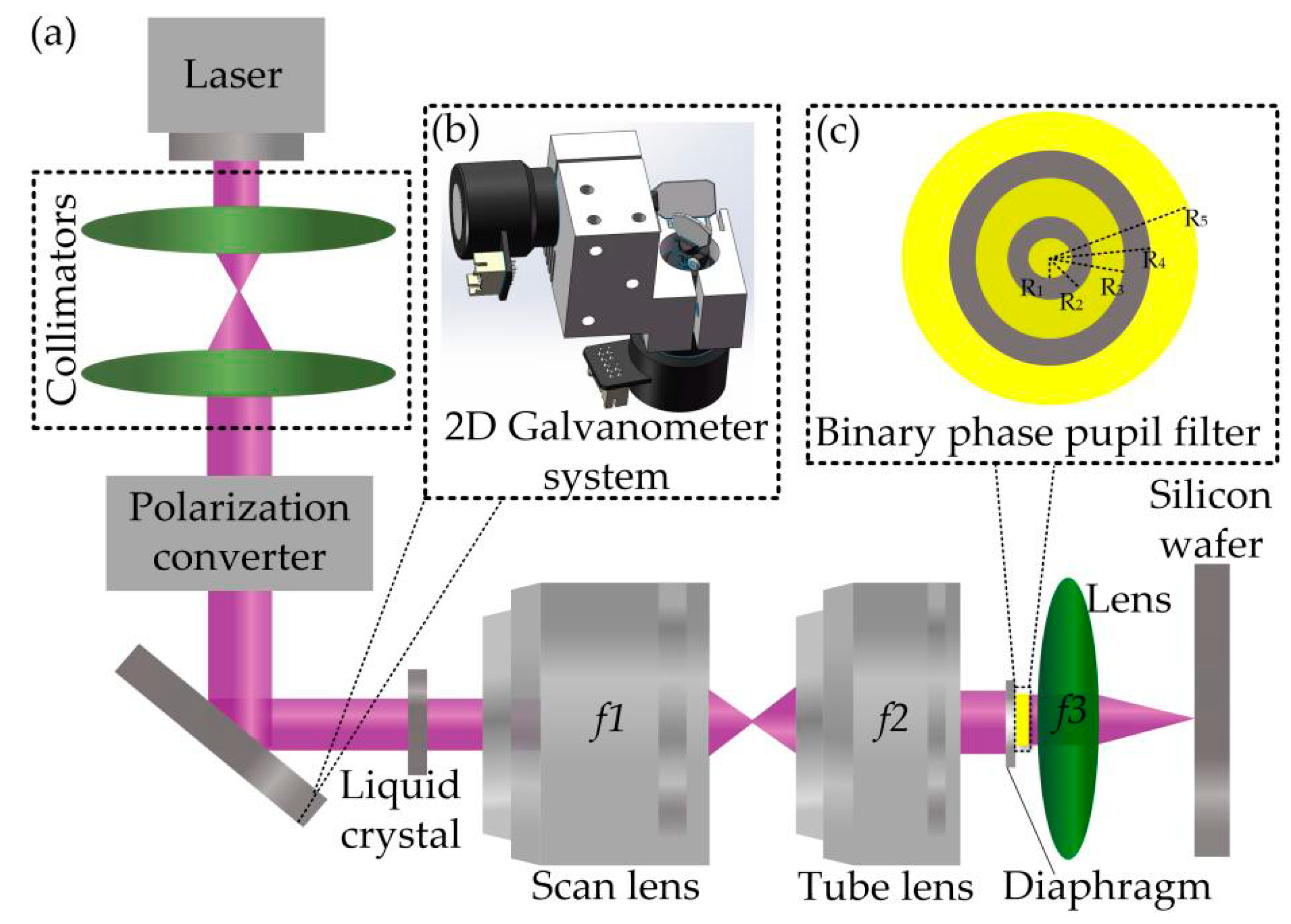
A schematic diagram of the optical setup is shown in
Figure 1. The radially polarized beam with a certain angle to the optical axis first passes through a confocal scanning system composed of a 2D galvanometer system, a scan lens, and a tube lens, then transmits through a binary phase pupil filter (BPPF), and is finally subsequently focused by a high NA lens. A radially polarized beam can be generated by modulating a linearly polarized laser beam with a polarization converter. The structure of the BPPF is shown in
Figure 1c. A phase difference of
is created between the bright yellow and dark gray regions of the BPPF. The three-dimensional view of the 2D galvanometer system is shown in
Figure 1b. The radially polarized beam can be deflected by the galvanometer mirrors in the x- and y-directions. For convenience, a box labeled liquid crystal is used to indicate a voltage-controlled liquid crystal that can produce small phase differences. The axis center of the x-axis galvanometer is at the same level as the focus of the scan lens (
f1), tube lens (
f2), and the high NA lens (
f3). Because any lateral motion would distort the linearity of the scan, the galvanometer mirror must be placed at image planes conjugate to the entrance pupil. When passing through
f1,
f2, and
f3, the laser beams are parallel, but at different angles to the optical axis. Although the scanning optic is afocal, it acts as a focal system for the motion of the beam. At the field diaphragm, the angle between the laser beam and the optical axis is called the oblique incidence angle (
θ).
In the process of the interaction between light and substance, the high NA lens tightly focuses the light field to achieve spatial light field modulation. The optical needle produced by tight focusing of the radially polarized incident beam is formed by the coherent superposition of various spatial spectral components in the focused space. According to the principle of interference, a BPPF is used to further modulate the light field to reduce the focal spot size or extend the DOF. According to the principle of confocal scanning, the angle of incident light can be controlled by a 2D galvanometer system. Although oblique incidence attenuates the DOF, the DOF can be elongated by compensating for the additional phase difference caused by oblique incidence. Next, its optical propagation characteristics will be further analyzed.
3. Parameter Analysis and Theoretical Calculation
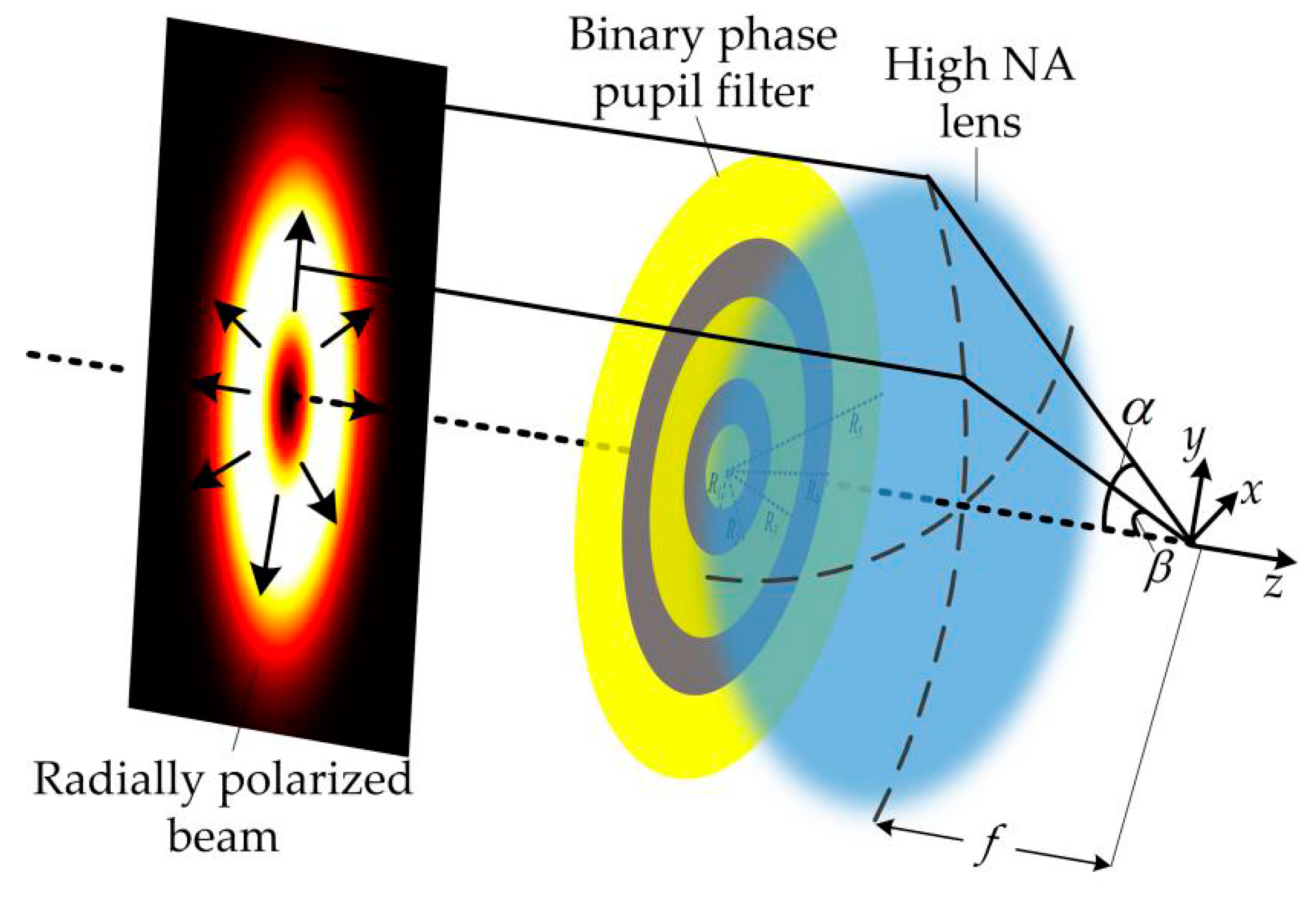
When the incident beam is perpendicular to the optical axis, the simplified schematic diagram from
Figure 1 becomes that shown in
Figure 2, where the radially polarized beam transmits through a BPPF and is subsequently focused by a high NA lens. According to Richards and Wolf’s vector diffraction theory, the transverse and longitudinal electric fields near the focal region in
Figure 2 can be written as Equation (1) and Equation (2), respectively.
In Equations (1) and (2), A is the coefficient of power (A = 1), k is the wavenumber (), and denote Bessel functions, describes the amplitude distribution of the incident beam, and is the maximum angle of the focus given by , where NA is the numerical aperture. In this manuscript, NA is set to 0.95, the refractive index , and the wavelength .
The transmission function of the BPPF is
, where
is the phase distribution corresponding to each ring. According to the principles of constructive and destructive interference, the simulated annealing algorithm [
18,
19] is used to optimize the filter structure. Using a five-ring BPPF, the angle
(i = 1~4) corresponds to the four radial positions
. For different ranges of the angle
,
or
. Therefore, the transmittance function can be expressed as
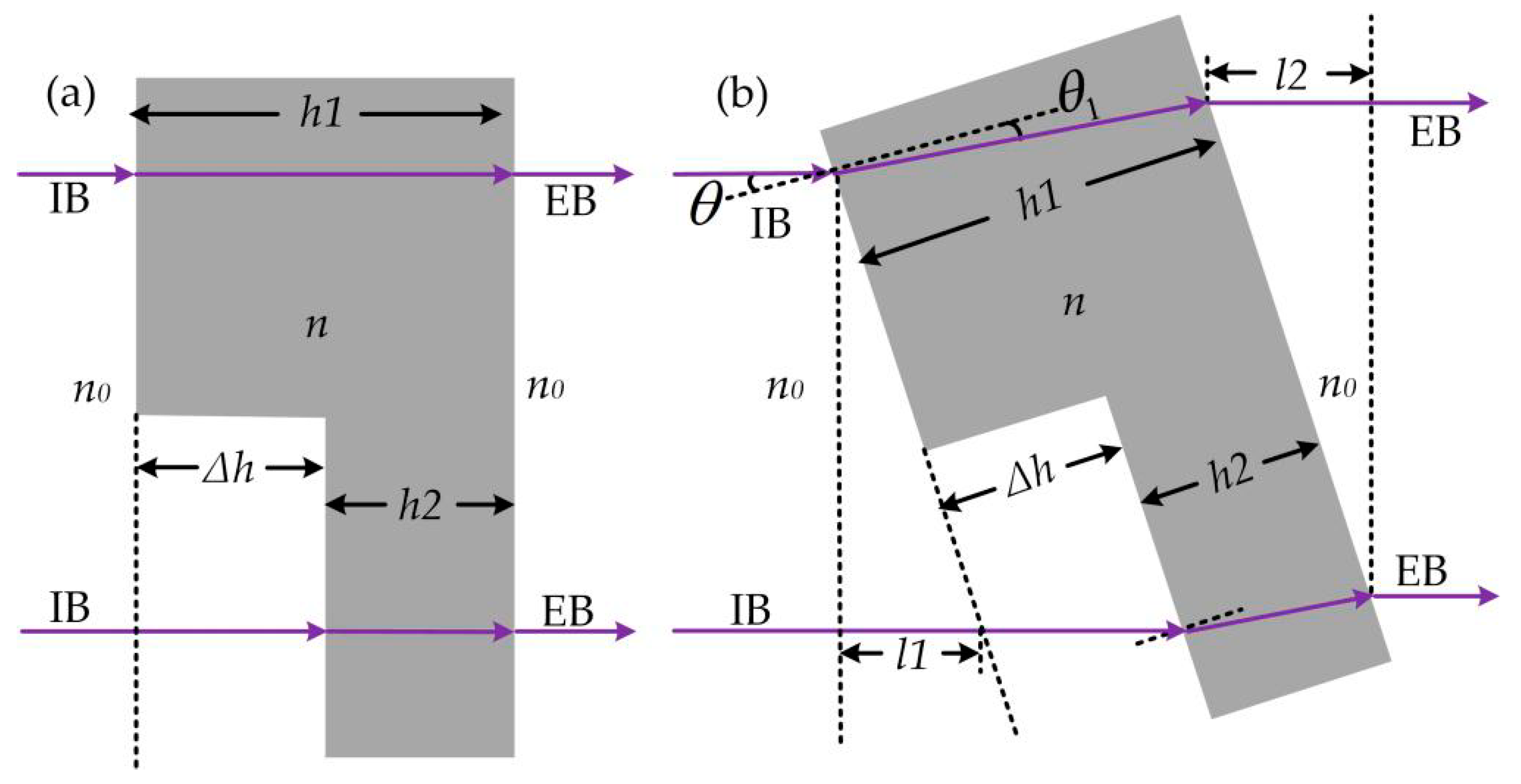
Essentially, the BPPF modulates the optical field through phase difference. When the focused beam is incident parallel to the optical axis, the oblique incidence angle is 0°, and the optical path difference of the phase modulation is completely derived from the BPPF, as displayed in
Figure 3a. In the case shown in
Figure 1a, oblique incidence adds additional phase difference. To simplify the calculation, the oblique incidence of a radially polarized beam can be regarded as the normal incidence of a radially polarized beam, while the BPPF is placed at a certain angle to the optical axis, as shown in
Figure 3b. In
Figure 3, the wider step (
h1) represents a phase of size
, and the narrower step (
h2) represents a phase of size 0.
When the BPPF is placed perpendicular to the optical axis, the optical path difference is
The corresponding phase difference is
where
n is the refractive index of the BPPF with wavelength
.
When the BPPF is placed obliquely, the optical path difference is
The angle between the BPPF and the optical axis is
, and the refraction angle is
. When
is small, the increased optical path of the incident beam (
) is considered equal to the increased optical path of the ejected beam (
). Based on the law of refraction (
),
can be simplified to
Therefore, compared to a BPPF placed perpendicular to the optical axis, a BPPF placed obliquely adds an additional phase difference (
):
As shown in Equation (9),
is related to the oblique incident angle
, and the transmittance function can be written as
The optical field distribution near the focus under the condition of oblique incidence can be obtained by substituting Equation (10) into Equations (1) and (2).
4. Simulations and Discussion
Based on the established theoretical model, the simulation was carried out using matlab software. Here, the influence of the oblique incidence angle on the characteristics of the MSON was analyzed. In addition, the voltage-controlled liquid crystal was selected for phase compensation of oblique incidence. By analyzing the characteristics of the MSON before and after compensation, a MSON with high aspect ratio that can move in the focal plane was obtained. Finally, the relationship between the moving distance of the MSON and the oblique incidence angle was established.
4.1. The Influence of Oblique Incidence Angle on the Characteristics of MSON
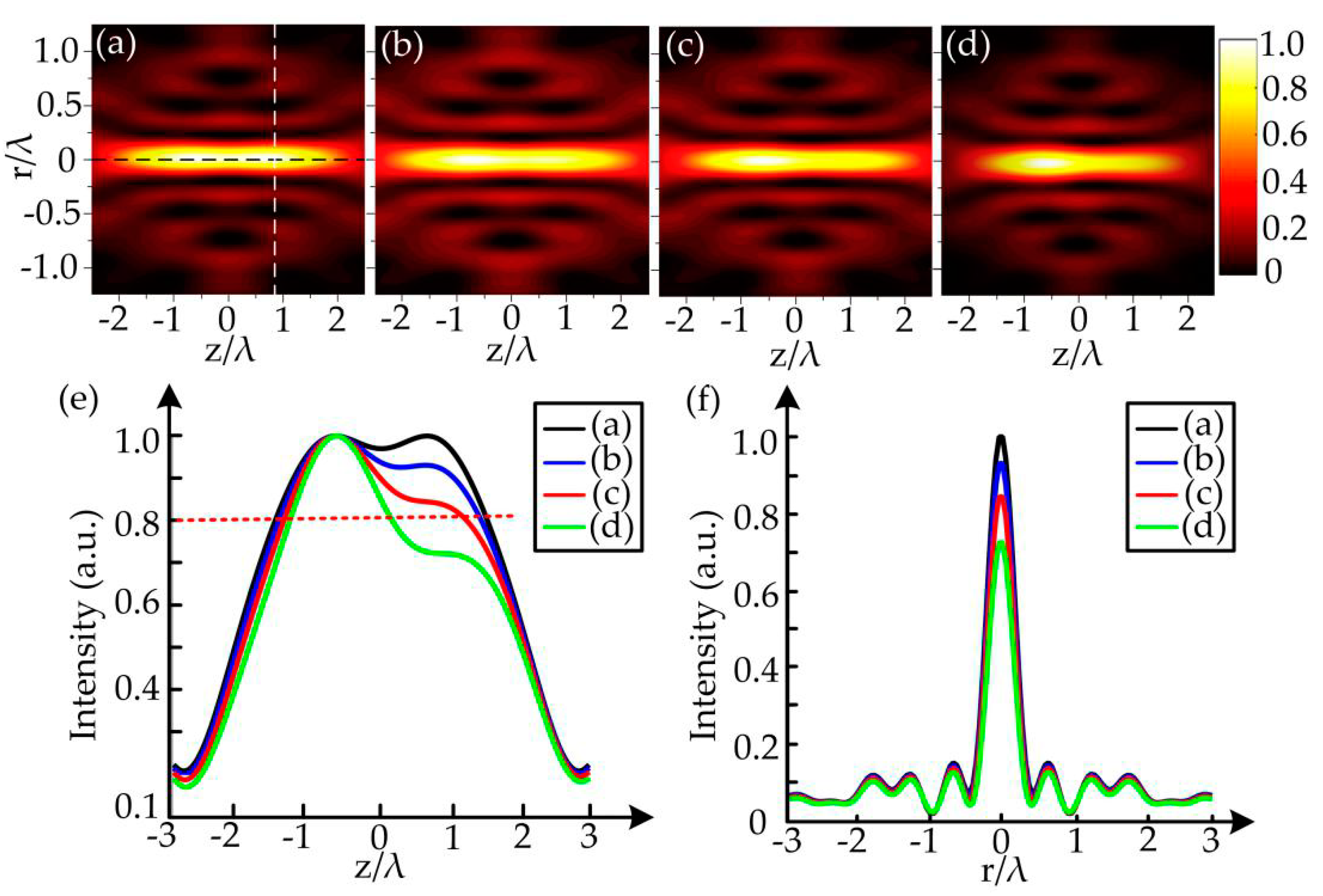
For oblique incidence, the light intensity distributions in the
r-
z plane at oblique incidence angles of 0°, 10°, 15°, and 20° are illustrated in
Figure 4a–d, respectively. Normally, the DOF of the MSON is measured by the axial length whose axial intensity is more than 80% of the maximum axial intensity, and the resolution is characterized by the maximum full width at half-maximum (FWHM) [
20] of all longitudinal plane optical fields. Moreover, when the light intensity is more than 0.8 times the maximum light intensity, the MSON is considered to have a homogeneous intensity. The intensity distribution in the transverse plane with
r = 0 (marked by a black dashed line in
Figure 4a) is plotted in
Figure 4e. For the longitudinal plane (marked by white dashed line in
Figure 4a), intensity distribution at
z = 0.7
λ is plotted in
Figure 4f. As expected, as the angle of oblique incidence increased, both the DOF and the uniformity of the MSON deteriorated. When the oblique incidence angle was 10°, the DOF and uniformity changed little. However, when the oblique incidence angle was 20°, the DOF was nearly attenuated by half compared with normal incidence. In addition, the resolution of the MSON remained the same as the oblique incident angle increased. However, the MSON had a tendency to focus to the left. This is because as the oblique incidence angle increases, the peak intensity on the longitudinal plane at
z = −0.7
λ remains almost constant, while the peak intensity of the longitudinal plane at
z = 0.7
λ decreases, especially when the oblique incidence angle is larger than 10°.
4.2. Characteristics of MSON before and after Compensation
In order to solve the DOF attenuation problem caused by the oblique incidence in principle, a voltage-controlled liquid crystal located between the scan lens and the 2D galvanometer system can be used to compensate for the additional phase difference caused by oblique incidence. The characteristics of the MSON obtained before and after phase compensation using voltage-controlled liquid crystal are compared in
Figure 5. As shown in
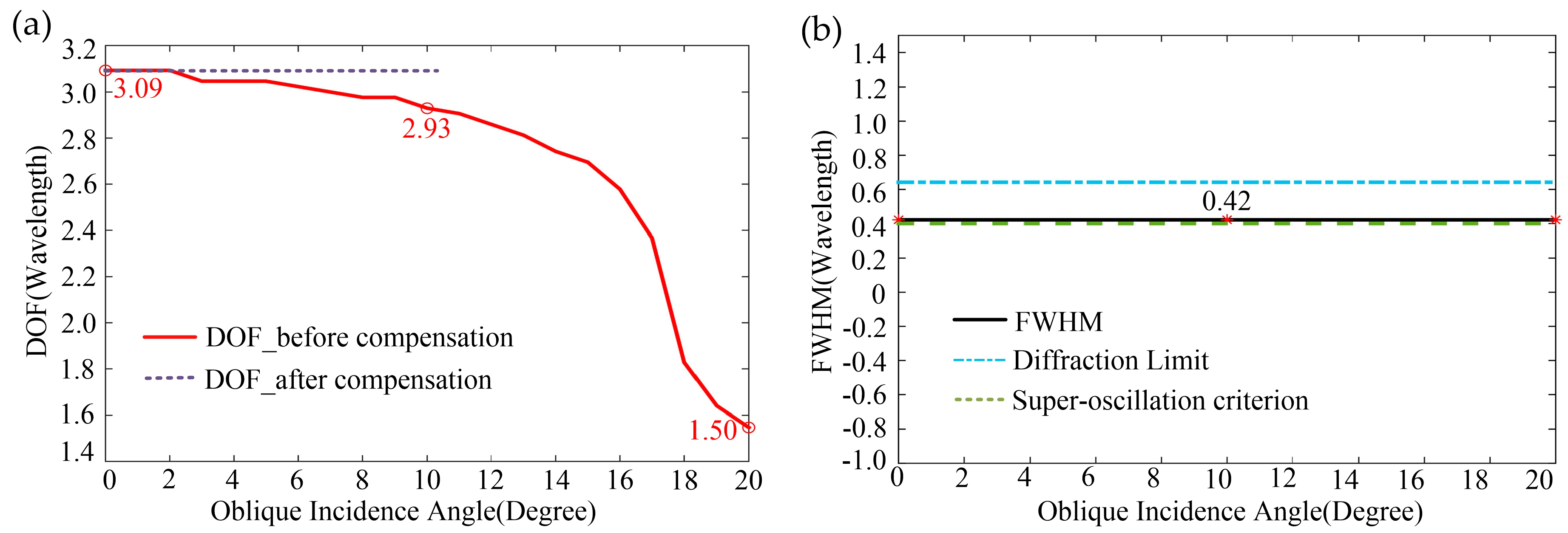
Figure 5a, when the incidence angle
θ = 0°, 10°, or 20°, the DOF before compensation was 3.09λ, 2.93λ, and 1.50λ, respectively. It can be found from the simulation results that the attenuation of DOF in the range of 10° was rather small. By adding a voltage-controlled liquid crystal to compensate for the additional phase difference caused by oblique incidence, the MSON with a constant DOF (3.09λ) in a specific angular range can be obtained. In addition, as shown in
Figure 5b, the FWHM of the MSON remained unchanged at 0.42λ. Optical focusing focal spot size is divided into sub-resolution (0.61λ/NA) and super-oscillation criterion (0.38λ/NA) [
21]. In the area between the two criteria, while achieving super-diffraction-limited focusing, the effect of side lobes can be effectively suppressed. Therefore, the MSON not only achieves super-diffraction-limited focusing, but also effectively suppresses side lobes.
The aspect ratio of the MSON is measured by the ratio of DOF to resolution as shown in Equation (11) [
22]. The aspect ratio of the MSON is as high as 7.36.
4.3. The Relationship between the Moving Distance of the MSON and the Oblique Incidence Angle
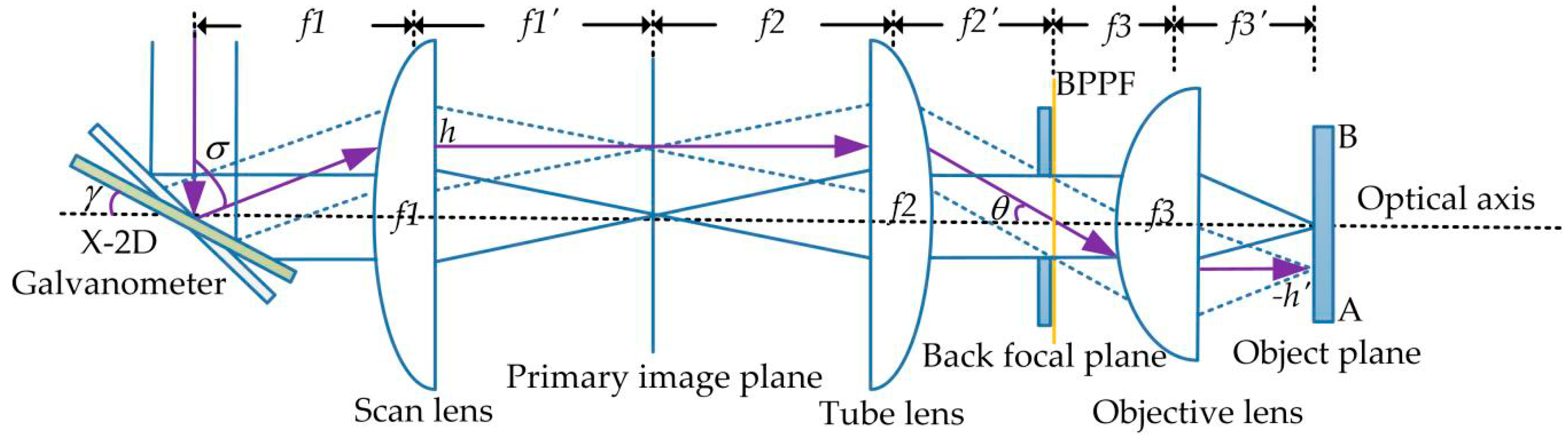
Apart from the characteristic analysis, the relationship between the position of the MSON and the angle of incidence should be further stressed. The simplified optical path diagram of the schematic diagram in
Figure 1a is shown in
Figure 6. In
Figure 6,
f1,
f2, and
f3 represent the object focal lengths of the scan lens, the tube lens, and the high NA lens, respectively. The distance from the reflected beam to the optical axis is
h, and the angle between the reflected beam and the incident beam is
σ. The axis center of the x-axis galvanometer is at the same level as the focus of the scan lens (
f1), tube lens (
f2), and the high
NA lens (
f3). According to the geometric optical path shown in
Figure 6, a mathematical model can be established. The relationship between the oblique incident angle (
θ) and the deflection angle of the x-axis galvanometer (
γ) can be expressed as Equation (12), and the moving distance (
h’) of the MSON and the galvanometer deflection angle (
γ) satisfy Equation (13).
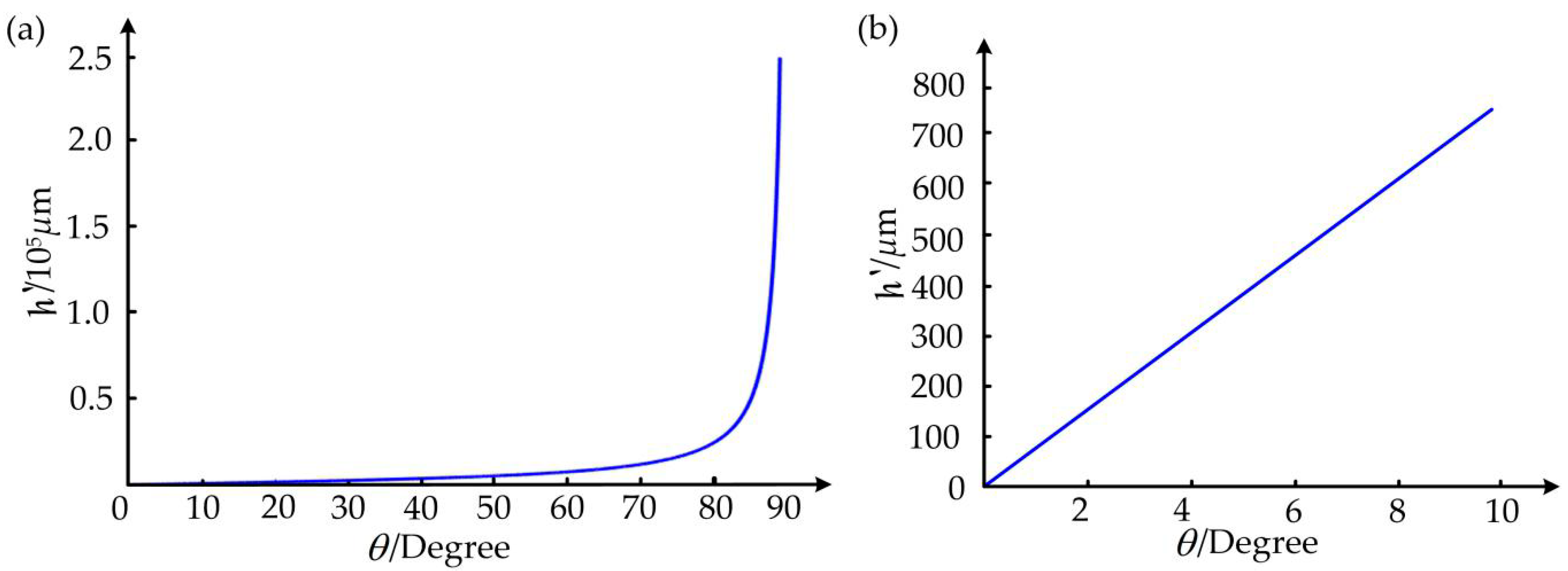
The radius selected for the high NA lens was 13.2mm. The moving distances (
h’) of the MSON for different oblique incident angles (
θ) can be calculated by Equation (13). The results are shown in
Figure 7.
Figure 7a shows that the moving distances (
h’) of the MSON and the oblique incident angle (
θ) were non-linear. In contrast, as shown in
Figure 7b, for the case where the oblique incidence angle was less than 10°, the moving distances of the MSON and the oblique incident angle were approximately linear. When the oblique incident angle was 10°,
h’ = 765.0176 μm. The 2D galvanometer system can make the oblique incidence angle change in the range of [−10°, 10°]. Therefore, the MSON can be arbitrarily moved in a 2D focusing plane with a size of [−765.0176 μm, 765.0176 μm]. This provides a strong basis for constituting small-scale vector scanning. Within the range [−765.0176 μm, 765.0176 μm], by controlling the angle of oblique incidence, the MSON can move linearly on the two-dimensional focus plane to achieve vector scanning. When the range exceeds [−765.0176 μm, 765.0176 μm], combined with mechanical scanning, the speed of laser processing can also be increased.
5. Conclusions
In summary, the galvanometer can control the oblique incidence angle of the incident beam. Through the establishment of mathematical and physical models, simulation analysis found that the DOF was attenuated with the increase of the oblique incidence angle, while the resolution remained unchanged, and the moving distance of the optical needle in the focal plane was proportional to the oblique incidence angle (θ ≤ 10°). For oblique incident focal depth attenuation problems, voltage-controlled liquid crystal can be used for phase compensation. Finally, we obtained a high-aspect-ratio (7.36) MSON with sub-diffraction beam size (0.42λ), long depth of focus (3.09λ), homogeneous intensity, and suppressed side lobes. Combined with mechanical scanning, applying the obtained MSON to laser processing can not only increase the speed of laser processing, but also solve the scientific problem that the resolution and DOF of traditional laser processing are mutually restricted. The sub-wavelength cross-section and large focusing depth of the MSON can achieve high resolution for nanolithography and high tolerance in axial positioning. Further study of the MSON experiment will be carried out, which will effectively improve the understanding of MSONs. In addition, it may be possible to further increase the resolution and DOF with more complex filters. The modulation and control technology for generating movable super-diffraction optical needles by oblique incidence can be widely used in optical micromachining and photolithography. In particular, it provides a new idea for preparation of high-aspect-ratio sub-wavelength structures. The optical needle we developed also has other important applications, including optical manipulation, particle acceleration, laser cutting, optical trapping, etc.
Author Contributions
S.W. proposed the method, established a model, and conducted simulations; S.W., W.Y., L.S., B.Q., F.L., S.Y., F.P. and J.D. analyzed the data; S.W., W.Y., L.S. and F.L. wrote the paper; L.S. and W.Y. applied for the funding and managed the project. All authors read and agreed to the published version of the manuscript.
Funding
This research was supported by the National R&D Program of China (No. 2017YFC0804900), the Instrument Development of Chinese Academy of Sciences (No. YJKYYQ20180008,YJKYYQ20180006), Sichuan Science and Technology Program (No. 2020JDJQ0007), the Youth Innovation Promotion Association, Chinese Academy of Sciences (CAS); CAS “Light of West China” Program, Microelectronic Equipment Sichuan Province Youth Science and Technology Innovation Team (J17S006), and Microelectronic Equipment Sichuan Youth Science and Technology Innovation Research Team (No. 2016TD0021).
Conflicts of Interest
The authors declare no conflict of interest.
References
- Li, Y.; Jiang, X.; Li, R.Q.; Liang, B.; Zou, X.Y.; Yin, L.L. Experimental realization of full control of reflected waves with subwavelength acoustic metasurfaces. Phys. Rev. Appl. 2014, 2, 064002. [Google Scholar] [CrossRef]
- Ran, L.; Canonico, M. Applications of UV-Raman spectroscopy and high-resolution X-ray diffraction to microelectronic materials and devices. Microelectron. Eng. 2004, 75, 243–251. [Google Scholar]
- Jiang, H. Development and Forecast of the Laser Processing Technology Application. Optoelectron. Technol. Inf. 2001, 4, 1–12. [Google Scholar]
- Zankovych, S.; Hoffmann, T.; Seekamp, J.; Bruch, J.U.; Torres, C.M.S. Nanoimprint lithography: Challenges and prospects. Nanotechnology 2001, 12, 91–95. [Google Scholar] [CrossRef]
- Born, D.; Wagner, T.; Krech, W.; Hubner, U.; Fritzsch, L. Fabrication of Ultrasmall Tunnel Junctions by Electron Beam Direct-Writing. IEEE Trans. Appl. Supercond. 2001, 11, 373–376. [Google Scholar] [CrossRef]
- Kuebler, S.M.; Tal, A.; Chen, Y.-S. Preparation of metallo-dielectric photonic crystals by multi-photon direct laser writing. In Proceedings of the Photonic Crystal Materials and Devices VII, San Jose, CA, USA, 21–23 January 2008; Volume 6901. [Google Scholar] [CrossRef]
- Friese, M.E.J.; Nieminen, T.A.; Heckenberg, N.R.; Rubinsztein, D.H. Optical alignment and spinning of laser-trapped microscopic particles. Nature 1998, 394, 348–350. [Google Scholar] [CrossRef]
- Zhan, Q. Trapping metallic Rayleigh particles with radial polarization. Opt. Express 2004, 12, 3377–3382. [Google Scholar] [CrossRef] [PubMed]
- Meier, M.; Romano, V.; Feurer, T. Material processing with pulsed radially and azimuthally polarized laser radiation. Appl. Phys. 2007, 86, 329–334. [Google Scholar] [CrossRef]
- Dorn, R.; Quabis, S.; Leuchs, G. Sharper focus for a radially polarized light beam. Phys. Rev. Lett. 2003, 91, 233901. [Google Scholar] [CrossRef]
- Sheppard, C.J.R.; Choudhury, A. Annular pupils, radial polarization, and superresolution. Appl. Opt. 2004, 43, 4322–4327. [Google Scholar] [CrossRef]
- Zhang, Y.; Bai, J. Improving the recording ability of a near-field optical storage system by higher-order radially polarized beams. Opt. Express 2009, 17, 3698–3706. [Google Scholar] [CrossRef] [PubMed]
- Zhan, Q.; Leger, J.R. Focus shaping using cylindrical vector beams. Opt. Express 2002, 10, 324–331. [Google Scholar] [CrossRef] [PubMed]
- Wang, H.; Shi, L.; Lukyanchuk, B.; Sheppard, C.; Chong, C.T. Creation of a needle of longitudinally polarized light in vacuum using binary optics. Nat. Photonics 2008, 2, 501–505. [Google Scholar] [CrossRef]
- Lin, J.; Yin, K.; Li, Y.; Tan, J. Achievement of longitudinally polarized focusing with long focal depth by amplitude modulation. Opt. Lett. 2011, 36, 1185–1187. [Google Scholar] [CrossRef] [PubMed]
- Wang, J.; Chen, W.; Zhan, Q. Engineering of high purity ultra-long optical needle field through reversing the electric dipole array radiation. Opt. Express 2010, 18, 21965–21972. [Google Scholar] [CrossRef]
- Rensch, C.; Hell, S.; Schickfus, M.V.; Hunklinger, S. Laser scanner for direct writing lithography. Appl. Opt. 1989, 28, 3754–3758. [Google Scholar] [CrossRef]
- Boissin, N.; Lutton, J.L. A parallel simulated annealing algorithm. Parallel Comput. 1993, 19, 859–872. [Google Scholar] [CrossRef]
- Zhao, Y.; Li, Y.P.; Zhou, Q.G. Vector iterative algorithm for the design of diffractive optical elements applied to uniform illumination. Opt. Lett. 2004, 29, 664–666. [Google Scholar] [CrossRef]
- Ma, W.; Zhang, D.; Zhu, L.; Chen, J. Super-long longitudinal magnetization needle generated by focusing an azimuthally polarized and phase-modulated beam. Chin. Opt. Lett. 2015, 13, 052101. [Google Scholar]
- Huang, K.; Ye, H.; Teng, J.; Yeo, S.P.; Luk’yanchuk, B.; Qiu, C.W. Optimization-free superoscillatory lens using phase and amplitude masks. Laser Photonics Rev. 2014, 8, 152–157. [Google Scholar] [CrossRef]
- Gentselev, A.N.; Dul’tsev, F.N.; Kondrat’ev, V.I.; Lemzyakov, A.G. Formation of Thick High-Aspect-Ratio Resistive Masks by the Contact Photolithography Method. Optoelectron. Instrum. Data Process. 2018, 54, 127–134. [Google Scholar] [CrossRef]
© 2020 by the authors. Licensee MDPI, Basel, Switzerland. This article is an open access article distributed under the terms and conditions of the Creative Commons Attribution (CC BY) license (http://creativecommons.org/licenses/by/4.0/).


