Abstract
Post-planting operations (e.g., fertilizing, cover crop planting) with a tractor and towed cart in standing crop (e.g., corn) are challenging. Tractor and cart should be kept within a certain boundary region to avoid crop damage. An automatic guidance system on the tractor is the solution of the issue; however, tractor’s auto-guidance does not guarantee the cart clear and exact following of the tractor. There is insufficient research in automatic control of a towed cart. Therefore, this research was undertaken to design a controller to manage lateral and longitudinal positions of a tractor-towed cart. A novel fuzzy logic based adaptive controller algorithm is proposed to control tractor-cart system steering with additional steering torque for the cart, ensuring that the entire system follows the desired trajectory within the set constraints. A hydraulic drive design for the cart was developed with a control principle to closely follow the tractor’s path and minimize damage to the plants. The proposed steering algorithm and designed controller were validated with interchangeable trajectory patterns via simulations in MATLAB/Simulink. The results demonstrated that the performances of the designed hydraulic drive and the accuracy of the proposed control algorithm were appropriate to steer the towed-cart with minimal damages on plant rows.
1. Introduction
Fully autonomous steering systems are becoming more common in agriculture. Agricultural machines operate in highly uncertain and unstructured environments due to varying soil and terrain conditions. Accuracy and robustness of agricultural controllers are important to achieve required precision in these environments [1]. An adaptive controller system capable of steering an agricultural vehicle operating in tightly constrained plant rows needs to be highly accurate requiring intelligent computation algorithms. Commercial off-the-shelf technologies and many research studies mostly focus on guiding and steering only tractors. However, many agricultural operations are performed after crop emergence and include a hitched cart behind a tractor or planter. Although improving the path tracking accuracy of a tractor along the desired trajectory is important, it alone cannot guarantee that the cart follows the tractor’s track because, the only controlling factor, is the tractor’s steering angle [2]. Unbalanced movements of the cart can easily increase crop damages and reduce yield. Feng et al. [3] revealed that the wheel trajectories between tractor and cart are different and often change according to steering angle and turning velocity. The lack of studies on automatic steering control of tractor’s towed cart operational in post-crop and cover crop procedures motivated the present study. An ultimate objective of this study is to design an accurate and easy to implement controller for a tractor-cart system to increase the precision of agricultural post-planting procedures and reduce crop damages and yield losses.
One of the earliest vehicle system models used in modelling motion of agricultural vehicles is standard automobile model that is based on a single axle system that does not represent two-axle systems. Alexander et al. [4] developed a basic lateral dynamic model by adding one more axle (rear tandem axle) to a standard automobile model and enhanced that basic model by incorporating second order dynamics into steering axle tires. Both basic and enhanced models gave accurate results at frequencies below 1 Hz. In a study of automated navigation for agricultural vehicles, Feng et al. [3] developed a generic model (independent of type and size of vehicles) based on a bicycle model that used a simple two degrees of freedom yaw plane approach and combined left and right tires on flat ground. Other well-studied models are constant velocity models (only applicable to straight-line motion), and coordinated turn model (only applicable while turning) which are inspired by Rajamani [5] who studies a dynamic model of vehicles. However, according to Jeon et al. [6], neither of these models can be used for combined scenarios and a single nonlinear model was proposed to encompass both straight line and turning motions which only considered longitudinal and lateral locations of vehicle and assumed zero tires’ slip angles.
Zhao et al. [7] showed that traditional controllers have difficulty in guaranteeing performance and stability and presented a new adaptive PID control system architecture of autonomous vehicle, in which a two degree-of-freedom dynamic model was developed to formulate path-tracking problem in state space format. Delavarpour et al. [8] suggested a closed loop adaptive control block model of steering-vehicle-sensor system for better controlling agricultural vehicles. Yin et al. [9] combined fuzzy and PID controls with kinematic model and proposed to adjust the real-time data of the PID parameters. Hodge et al. [10] proposed two fuzzy logic controllers for steering and velocity control of an autonomous vehicle in hazardous environments or intelligent highway systems. For a path-tracking problem of an electric system, Allou et al. [11] designed a simple and effective controller based on fuzzy logic, which sends speed and steering instructions to a robot to ensure that the robot follows the trajectory. Rovira-Ma’s and Zhang [12] used a fuzzy logic controller to create the electrical steering signals for a directional control valve solenoid deriver to auto steer an off-road vehicle. Revatkar et al. [13] demonstrated that a boost converter with Single Input Fuzzy Logic Controller was better than Proportional Derivative Controller and Conventional Fuzzy Logic controller in disturbances in load or reference voltage changes. For an autonomous guidance system of a wheeled tractor-like-robot on sloping terrain, a Neural Network (NN) vehicle model for slope lands was trained by a Back-Propagation algorithm [14]. An NN PID controller for lateral path tracking control based on a vehicle model and steering system model exhibited robust real-time path tracking control [15]. Zhang et al. [16] applied a neural network to keep and track a pre-given trajectory in the lateral control. Despite broad studies of auto-steering vehicles control systems (both on-road and off-road), the adaptive controller design for an agricultural chained vehicle (e.g., tractor-cart system) is not a well-studied topic and requires studies.
This study aims to address the automatic control of a towed cart by designing a fuzzy logic based adaptive control algorithm and controller to steer the lateral and longitudinal position of tractor and its towed cart in combination. The objective is to minimize viable position errors of the whole system while driving between plant rows. An analysis of previously reported research showed that a fuzzy logic-based control method applied in different control problems has been found to be an appropriate tool because of its simplicity and adaptability to varying conditions and control parameters. These features of the fuzzy logic-based controller approach motivated this study to apply the fuzzy logic controller principles in designing an adaptive controller for a tractor-cart steering system. Mathematical formulations of tractor and a cart motion are developed based on a kinematic bicycle model. A novel fuzzy logic based adaptive control algorithm is developed to steer the motion of the cart ensuring the motion of the tractor-cart system in accordance with the desired trajectory. To the best knowledge of the authors, the idea of using an adaptive fuzzy logic-based control algorithm for cart motion control of the tractor-cart system was never studied before.
The cart’s position is controlled with additional steering torque actuated by a pair of hydraulic cylinders with respect to the difference between its current position and reference pattern. The proposed hitch hydraulic design along with its mathematical model formulation and numerical simulations have never been undertaken before. The novel adaptive fuzzy logic based steering control algorithm with the designed hydraulic drive is validated via numerical simulations in the MATLAB/Simulink (MathWorks, Natick, MA, USA, 2019) environment. The advantages and disadvantages of proposed method are highlighted. This paper is organized in the following order: (1) Section 2 describes the derived equations of motion of the tractor-cart system and the designed active hydraulic hitch. (2) Section 3 explains the proposed control algorithm. (3) Section 4 presents the proposed fuzzy logic rules. (4) Section 5 describes the hydraulic cylinder design. (5) Section 6 presents simulation results of the developed controller in a MATLAB/Simulink environment, and (6) Section 7 highlights discussions of the study results.
2. Tractor and Cart System Modeling
Achieving a high level of precision in controlling off-road vehicles in unstructured agricultural environments is not as easy as on-road vehicles. Because agricultural machines operate in highly uncertain and uneven terrain conditions, self-aligning systems of these vehicles need further study with respect to their varying environments. There are many research studies dedicated to the auto steering and self-aligning whose controllers are used on tractors. Although the towed cart is the main source of damage to crop plants in a field, there are few studies on precise navigation of towed carts. To design an automatic guidance system for a towed cart, it is essential to understand steering kinematics and motion dynamics of the tractor and cart in various field conditions. In several studies [17,18,19] of tractor and cart tracking controller design, because of the low operating speeds (i.e., less than 10 m/s) of agricultural machines, the kinematic model was considered due to its simplicity. In this approach, it is assumed that the sideway slippage of tires is negligible, the inertia of the system is minimal and air-drag acting on the vehicle does not influence the system dynamics [20]. The demonstrated results [21,22] for the kinematic model in control design showed highly accurate results within the range of interest. However, in higher operating speeds, the tire sideslip was not negligible, and forces acting on dynamics of cart need to be taken into account and analyzed. This study analyzes the behavior of tractor and its towed cart (single axle) motion of the system was modeled with a kinematic model approach. Accuracy, robustness, and overall performance of the tractor-cart automatic guidance controller based on the kinematic bicycle model were simulated and analyzed.
2.1. Kinematic Bicycle Model
The equation of motion of a vehicle is a combination of different assumptions. Engineering challenges in designing a control system are to choose the simplest possible model whose assumptions are sufficiently valid to allow accurate, robust, and/or adaptive control system design [23]. In this study, the tractor-cart behavior was studied in two different situations: (1) the cart is a follower and there is no active steering control over its movements; (2) the cart is actively guided. The proposed tractor-cart kinematic model presented in Figure 1 is composed of two parts: a tractor and cart, and the state variables of the system model. The information is presented in Figure 1 and given in Table 1.
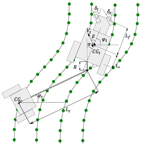
Figure 1.
Schematic representation of tractor-cart system.

Table 1.
Tractor and cart kinematic bicycle model parameters definition.
At the end of rows, while turning the two front wheels of a tractor, different angles relative to tractor’s body are created. The first assumption in this kinematic bicycle model approach was to combine the effects of the two steering wheels and consider them parallel to each other by assuming . In other words, the front wheels were considered as a single unit. The same assumption was also made for rear wheels.
Figure 2 shows the proposed kinematic bicycle model under the following assumptions: (1) the front wheels are the only steering wheels, and rear wheels (rear axle) are followers and the velocity vectors, at the front and rear axles of tractor, are in the direction of the orientation of the front and rear wheels, respectively; (2) the second assumption is that the center of the gravity () of the cart resides on the axle of the cart. The definition of all terms used in Figure 2 are given in Table 1.
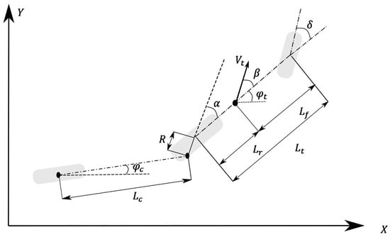
Figure 2.
Kinematic bicycle model of the tractor-cart system.
According to the assumptions stated above, the kinematic bicycle model of the tractor-cart system is shown in Figure 2. The equations of motion of the tractor are expressed in (1) and (2):
The angular velocity of the cart without a controller is expressed in Equation (3), and with a controller in Equation (4):
In this model, the front wheels were assumed to be the steering wheels, taking the input control signal to control (steer) the motion of the tractor. The main task of the anticipated controller was to make the tractor follow the reference path as closely as possible. In most of the models reported in literature devoted to vehicle and cart motion, the slip angle is not considered. In this model, the effect of slip angle was considered. In a second input control signal , the hitch control was taken to steer the hitch arm in order to minimize the error of the cart position with respect to the reference pattern. The tractor velocity was assumed to be constant. By discretizing differential Equations in (1), (3), and (4), and integrating them with respect to the sampling time (: sampling frequency), and updating controller’s equations with control signals, the next Equations (5)–(7) were derived:
where . The cart position without and with a controller is given in Equations (8) and (9), respectively:
The resulting state vector of the overall kinematic model is expressed by Equation (10):
The overall control vector is given in (11):
Finally, a generalized system model is expressed in (12):
Row patterns of crops in the fields in general do not change abruptly and don’t have sharp curves. Thus, angles of , , and can be considered to have relatively small values. To simplify and linearize the model equations given in (5)–(9), all the trigonometric functions were substituted with their fourth and fifth degree Taylor Series expansions. The system Equations (5)–(9) were re-written in (13)–(17):
Note that the angles , , , and are in radians.
2.2. Hydraulic Hitch Modeling
An active cart guidance system steers the cart independently and allows the cart to operate independently within the limits of tractor’s steering. The hitch steering system is used to control the cart position with respect to changes in the reference pattern. A hydraulic drive was taken as an actuator, mounted on the rear axle of the tractor. The proposed hydraulic hitch design shown in Figure 3 takes the changes within the extension length of a pair of cylinder rods ( and ). The extension change in cylinder rods leads to the hitch angle () and, subsequently, the hitch arm (R) position changes with respect to tractor’s rear axle centerline. Changes in angle () result in changes in the cart position. The hydraulic hitch actuator controls the length of hydraulic cylinder rods, hitch angle (), and hitch arm (R). The following geometric parameters for the proposed hydraulic actuator unit were taken: , and . The turning angle (α) ranges within: .
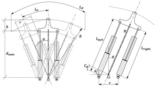
Figure 3.
Hydraulic hitch model and its parameters.
The hydraulic equation of the cylinder speed is . is extraction and its retraction length in one cylinder is equal to
where is velocity (retracting or extending motion) of a hydraulic cylinder rod, is a sampling time, is the area of either blind end or rod end side (depends on the direction of hydraulic cylinder motion), and is the pump flow rate going to the cylinder. is the length interval depends on the position change of the hitch within and , is the arc length changing within and , and r is the distance between two cylinders.
According to the geometry of hydraulic hitch design , the angle (α) of hitch arm is calculated from Equation (19):
The length of left and right cylinders of hydraulic hitch is calculated from the next equation:
The variable and must be controlled with respect to translational speed of the hydraulic cylinder. It should be noted that hitch arm (R) turns to the angle due to translational motions of two hydraulic cylinders and angular velocity is equal to the change of angular displacement values in a unit time as .
3. Control Algorithm
The adaptive control model’s flowchart of the tractor-cart system is shown in Figure 4. The control strategy is similar to our previously proposed model [8]. The purpose of this controller was to control heading angle of the cart to adjust its position change with respect to coordinates of the reference path. First, the current position of tractor and cart are calculated with respect to the reference trajectory. Errors of tractor and cart position from the reference trajectory are calculated and entered as the inputs to the designed fuzzy logic controllers to estimate the desired steering angle for tractor and required pump flow rate for cart’s hydraulic hitch, in order to generate the sufficient torque to correct the position of tractor and cart, respectively. Next, the new positions of tractor and cart are calculated again to compare the offset between reference trajectory and system. A threshold range of ± 2 cm is used to repeat the whole procedure in case of error beyond the threshold; otherwise, the process continues to the next point. An active controller for the cart was implemented and a fuzzy logic rule-based controller was applied to a steer tractor and hitch of a cart simultaneously with respect to a given reference row patterns of plants. In a feedback control algorithm shown in Figure 5, input variables to fuzzy logic controller (FLC) were the position error and change-of-error rate signals. Fuzzy logic inputs to tractor’s steering angle controller were the differences or errors of the current position of tractor’s C.G. with respect to the reference model , which were lateral and longitudinal coordinate positions. The error differences or change rates also were fed to tractor’s steering controller. The output of this controller was the steering angle also were fed to tractor’s steering controller. The output of this controller was the steering angle to correct the position of tractor. The same approach was applied for the cart’s controller. In the cart’s controller, the input signals were errors used to compute cart’s coordinates with respect to the reference pattern as well as the error difference or change rates . The output of this controller was the flow rate into hydraulic hitch to correct the cart position. These estimated values of fuzzy controllers were substituted in tractor and cart position Equations (13), (16), and (17), which are linearized forms of (5), (8), and (9), in order to calculate the current positions of the tractor and cart.
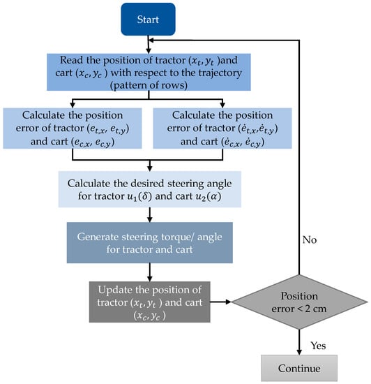
Figure 4.
Flow chart of position control procedure for the tractor-cart system for path tracking.
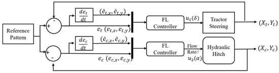
Figure 5.
Tractor-Cart adaptive control block model.
4. Fuzzy Logic Rules
In designing fuzzy logic controllers, Mamdani reasoning [24,25,26,27,28] and Centroid methods [29,30] in de-fuzzification were used. A triangular function was adopted to define membership functions. The reason for choosing a simple linear membership function was that it reduces the computational burden considerably and is easy to tune. Membership functions for the inputs and output signals of tractor controller are shown in Figure 6. The error signals and their change rates were represented via three membership functions NF, VC, PF, and N, Z, and P, respectively. Linguistic terms of the membership functions are presented in Table 2. The cart controller is presented in Figure 7 with the same linguistic terms used for the tractor controller (Table 2). Output function rules for both controllers are composed of 81 rules (Table 3). Eighty-one rules cover all possible case scenarios and are capable of considering relatively small offsets from the reference path.
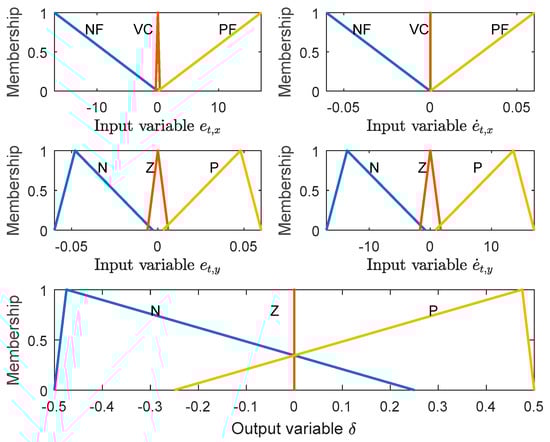
Figure 6.
Fuzzy logic membership functions for the inputs and outputs of steering angle.
Table 2.
Linguistic terms definition.
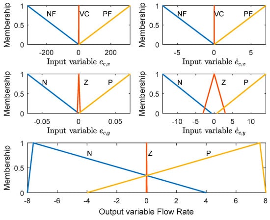
Figure 7.
Membership functions of the input and output variables of the cart controller.
Table 3.
Fuzzy logic controllers.
5. Hydraulic Cylinder Design
To design a hydraulic actuator for hitch, the required hydraulic flow rates to pull/push the hitch arm and change the angle of cart to correct its position was taken with respect to the Case IH Magnum 310 with maximum 380 hp and 44 GPM. The dimensions and weight of the cart was taken from Amity ST250 Air Cart (Amity technology, Fargo, ND, USA) with a capacity of 200 bushels (up to 7 tons). According to the tractor power and cart specifications, a chosen hydraulic cylinder should be capable of changing the direction of hitch arm within a required range (considering the distance between plant rows). The parameters of the selected hydraulic cylinder are given in Table 4. The linear relationship between the cylinder rod’s linear motion and angular displacement (α) of the hitch arm is shown in Figure 8.
Table 4.
The hydraulic cylinder specifications.
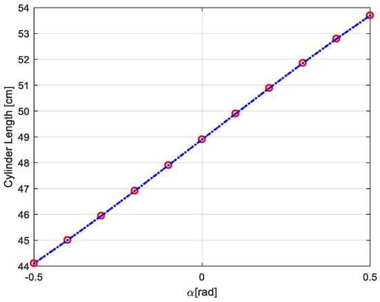
Figure 8.
Relation between α vs. cylinder’s rod translational motion.
A fully retracted length of the chosen cylinder is 41.2 cm, and its fully extended length is 56.51 cm. The cylinders move in parallel with the hitch arm. Therefore, the length of the cylinders in the normal situation () is equal to 50 cm. The maximum and minimum stretched length of the cylinders (left or right) with respect to values is .
The required flow rate change with respect to the length of the cylinder was calculated from Equation (21):
where Stroke Length is extension or retraction of the cylinder rod; Cylinder Area for retraction is the area of rod end (13.87 ) and for extension is the area blind end (20.25 ). Since the sampling frequency in this study was 20 Hz, the Stroke Time is 0.05 s. For stroke time = 0.05 s, the maximum flow rate was required to change from −0.5 to 0.5 rad or change the cylinder length from fully extended to fully retracted. For this cylinder with a maximum flow rate of 44 GPM, the speed of moving from fully retracted to fully extended is 53.95 in/s = 1.37 m/s and for moving from fully extended to fully retracted is 78.79 in/s = 2 m/s. Figure 9 shows the relationship between the required flow rate and angular displacement rate of the hitch arm . For double acting cylinders, the left side of the plot (Figure 9) represents retraction and the fluid flows through rod’s end hose. The right side of the plot (Figure 9) represents extension where the oil flows through the blind end hose.
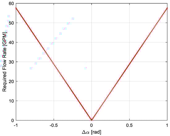
Figure 9.
Relationship between changes of hitch arm angle vs. required flow rate.
6. Results and Discussion
In order to evaluate the proposed algorithm based on fuzzy logic rules to control the motion of the tractor and cart, computer simulations of the derived models of system were performed [31,32,33] in a MATLAB/Simulink environment [34]. Reference patterns of plant rows to analyze performances of designed controllers, velocity of tractor are given in Table 5.
Table 5.
Simulation study cases and parameter values.
The influence of uneven and off-road terrain profile, time delays due to friction, and steering loads have been neglected. Simulation results showed that the proposed controller was able to move the hitch arm to keep a cart in a correct path within −0.06 to 0.06 rad with respect to the given plant rows. For relatively small values of α, oil flow rates of 6 GPM was enough to make the required change in time for any speed of 1 to 10 m/s. Figure 10 shows the time delay for changing the pump flow rate and changing the cart position. The analytical and numerical results showed that time delay was relatively small, and the pump flow rate (max 44 GPM) was sufficient to make the hitch arm move without considerable delays.
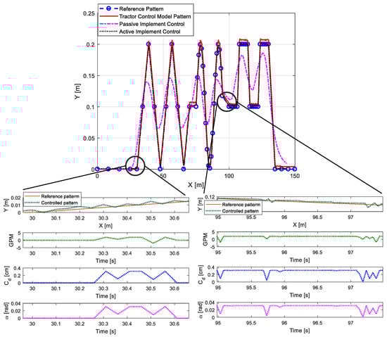
Figure 10.
Time delay between sending correcting signals to pump and taking action by cylinder.
The performance of designed controller to steer the tractor-cart system with respect to the correct path of motion was tested in four different patterns of plant row patterns and at different speeds from 1 to 10 m/s of the tractor-cart system. Due to high number of rules of adaptive fuzzy logic controller, the controller could correct the position of the tractor and cart with the reference pattern. In Figure 11, Figure 12, Figure 13, Figure 14 and Figure 15, the reference pattern, tractor passed path (with controller), cart without a controller, and with the designed controller are shown.
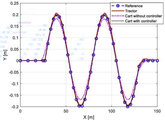
Figure 11.
Performances of tractor-cart position control system under a sinusoidal pattern at 1 [m/s].
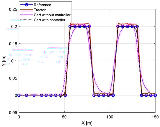
Figure 12.
Performance of tractor-cart position control system under a Pulse pattern at 3 [m/s].
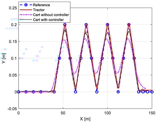
Figure 13.
Performance of tractor-cart position control system under a Zigzag pattern at 5 [m/s].
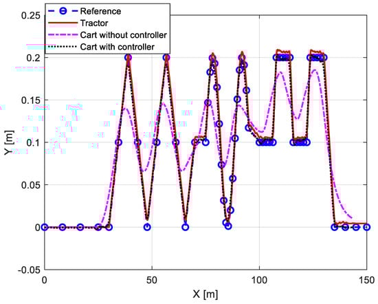
Figure 14.
Performance of tractor-cart position control system under a Mixed pattern in 2 [m/s].

Figure 15.
Performance of tractor-cart position control system under a Mixed pattern in 4 [m/s].
The first simulation pattern was a sinusoidal wave with moderate amplitude changes along the row length—Figure 11. The simulation results showed that the proposed controller is capable of keeping the cart on the desired path within the set fluctuations. At a low speed of 1 m/s, cart’s offset without a controller from the reference pattern was calculated to be 10–20 cm. The designed active controller and hydraulic drive improved the behavior of the cart considerably and reduced the offset to <5 cm and the time delay to 0.03 s.
A more complex pattern with sharp changes along the rows was also tested. The system response of the tractor-cart controllers in this pattern were accurate for more than 96% at lower speeds (1–5 m/s). At higher speeds, the accuracy of the controller dropped slightly and was between 61% to 96% (Table 6). Figure 12 shows the simulation results at 3 m/s and the accuracy of the cart with the designed active controller was about 92% success in adjusting the position of cart according to the reference pattern with very marginal offsets.
Table 6.
Coverage percent (without controller/with controller).
The third pattern tested to evaluate the controller performances was a Zigzag pattern with more abrupt changes along the path. The position control of the cart in comparison with passively controlled system improved significantly, but the combination of increased speed and complex pattern reduced the accuracy far more than in the aforementioned patterns Figure 11 and Figure 12. The simulation results of the zigzag pattern at 5 m/s is shown in Figure 13. This demonstrates the reciprocal relationship between speed of running agricultural operations and accuracy of performing. Figure 13 shows that the proposed controller corrects the cart position for average of over 90% (at all speeds). The controller performance degrades in the peaks and valleys of pattern to ~2–3 cm. Without the proposed controllers, the cart had an average offset of 5–10 cm from the reference pattern and about 50% of accuracy.
The last generated pattern was a pattern with a combination of three previously considered patterns to assess the performance of the system control in a more complex pattern of plant rows. Figure 14, Figure 15 and Figure 16 indicate the cart behavior with and without a controller at three different speeds (2, 4 and 9 m/s). Figure 14 demonstrates that, in the case of a complicated pattern in lower speed (<5 m/s), the controller could adjust the cart position according to the given path with the accuracy of ~2–3 cm and over 90% of accuracy for the whole simulation duration. Figure 15 shows the effect of higher speeds in reducing the accuracy of controller. The performance of the controller deteriorates, as it gets closer to the end of the pattern and almost loses a track of the row pattern in the final 25 m of simulation. Simulations in the highest speed at 9 m/s shown in Figure 16 show that the efficiency of the controller dropped significantly. The position accuracy of the cart with the controller dropped to 5 … 10 cm in magnitude and the accuracy without a controller was about 7–13 cm. A low controller accuracy with the increase of tractor’s driving speed and in abrupt row pattern changes were in agreement with the study results of Benson et al. [35]. Benson et al. [35] indicated that controllers of tractor-cart systems are quite effective at low speeds, i.e., up to 10 km/h (2.77 m/s) in maize, where the course is limited to straight rows, and the system could only be used on curved rows in slower speeds.

Figure 16.
Performance of tractor-cart position control system under a Mixed pattern in 9 [m/s].
The accuracy of the controller in finding the right path was calculated. The chosen range for the x-axis was −10 cm to 10 cm and −1 cm to 1 cm for the y-axis. Any reading beyond these ranges was not counted as an accurate reading (Table 6).
The proposed control model performances were compared with the results of other studies in a similar domain. Table 7 reports the comparison results of the studies reported by other researchers and the present work. Most of the proposed controllers in other studies for off-road vehicles were only able to control the tractor-trailer system up to 4.47 m/s. The proposed controller in this study could correct the position of cart accurately up to 5–7 m/s depending on the complexity of the reference pattern, which compared to other studies in Table 7, is a very good improvement. In most of the previous studies, the running speed of the tractor was considered as a major limitation of the controller, while the proposed fuzzy logic controller in this study is able to control the tractor-cart system up to 7 m/s. Another advantage of the proposed model is that it is simple and efficient in terms of the computation and processing time for optimal and adaptive control.
Table 7.
Comparison of previous studies and present work.
7. Conclusions
The equation of motion of the tractor-cart system was modeled using a kinematic bicycle model approach. Furthermore, to simplify the system models for small angular and low speed motions, Taylor Series expansion was introduced to substitute trigonometric functions in the system model. An 81 Fuzzy Logic (FL) rules-based controller for the tractor steering and cart hydraulic hitch was developed. The FL rules were designed to compute an adequate value of the steering angle and required flow rate from pump to hydraulic cylinders of cart’s hitch to change the position of cart and control its direction with respect to the actual row pattern of plants. The steering algorithm and designed controller were validated with different trajectory patterns via simulations in MATLAB/Simulink. The simulation results showed that the proposed fuzzy logic controller improves the behavior of cart up to 96% in lower driving speeds up to 5 m/s and up to 72% in higher running speeds 5 to 10 m/s in comparison to a passively controlled system. The best performance of the controller was observed in 1–4 m/s in a “sinusoidal” pattern, which is a running speed in most agricultural operations. Therefore, it was concluded that the computed values of controller parameters for and with the FL system were appropriate (for low speed and simple path) with respect to the computed error margins of the system trajectory. However, the main disadvantage of the fuzzy logic system is, for higher accuracy, more fuzzy rules are required to be designed, which require evaluation of the optimal rule values before hardware design.
The simulation results of the new hydraulic drive design showed that the retracting and extending speed of the hydraulic cylinder with respect to the provided flow rate from tractor’s hydraulic pump was adequate to turn the hitch arm with respect to the FL based controller output. The selected cylinder size was sufficient to meet the system requirements and taking the action with acceptable small-time delays in responses.
One of our future studies will be dedicated to implementing our proposed controller of the hitch arm to design a hydraulic cylinder and pump system with respect to the overall system parameters and field conditions. In the future studies, terrain and environment aspects will be considered in the system model equations. Another crucial study is to compare the result of designed fuzzy inference system (FIS) controller in this study with other common adaptive and model predictive controllers with applications of evolutionary algorithms, ANN, ANFIS-PSO, etc. or combination of these methods to validate and improve the performance of the proposed controller.
Author Contributions
N.D. conducted the experiments and simulation, designed experiments, and developed control algorithm and control strategy, analyzed data, wrote the manuscript, and edited it further. S.E. was responsible for overall supervision, prepared the structure of the study, developed the control algorithm and control strategy, system equations of motion and simulation models, reviewed the results, and edited the manuscript. T.B. validated the results and edited of manuscript. J.N. obtained the funding, wrote the project proposal, and corrected and edited the manuscript. S.B. corrected and edited the manuscript. All authors have read and agreed to the published version of the manuscript.
Funding
Coordinated Agricultural Program, award No. 2016-69004-24784, and the North Dakota Soybean Council.
Acknowledgments
This research was possible thanks to the funding provided by the North Dakota State University Agricultural Experimental Station project ND 01557, the USDA-NIFA award No. 2016-69004-24784, “CropSys—A novel management approach to increase productivity, resilience, and long-term sustainability of cropping systems in the northern Great Plains”.
Conflicts of Interest
The authors declare no conflicts of interest.
References
- Katupitiya, J.; Eaton, R. Precision Autonomous Guidance of Agricultural Vehicles for Future Autonomous Farming. 2008. Available online: https://www.researchgate.net/publication/268486952_Precision_Autonomous_Guidance_of_Agricultural_Vehicles_for_Future_Autonomous_Farming (accessed on 24 January 2020). [CrossRef]
- Backman, J.; Oksanen, T.; Visala, A. Nonlinear Model Predictive Trajectory Control in Tractor-Trailer System for Parallel Guidance in Agricultural Field Operations. IFAC Proc. Vol. 2010, 46, 133–138. [Google Scholar] [CrossRef]
- Feng, L.; He, Y.; Zhang, Q. Tractor-implement dynamic trajectory model for automated navigation applications. In Proceedings of the Third International Conference on Information Technology and Applications, Sydney, NSW, Australia, 4–7 July 2005; Volome 1, pp. 330–335. [Google Scholar]
- Alexander, L.; Donath, M.; Hennessey, M.; Morellas, V.; Shankwitz, C. A lateral Dynamic Model of a Tractor-Trailer Experimental Validation. 1996. Available online: http://dotapp7.dot.state.mn.us/research/pdf/199718.pdf (accessed on 24 January 2020).
- Rajamani, R. Vehicle Dynamics and Control; Springer: New York, NY, USA, 2012. [Google Scholar]
- Jeon, W.; Zemouche, A.; Rajamani, R. Tracking of Vehicle Motion on Highways and Urban Roads Using a Nonlinear Observer. IEEE-Asme Trans. Mechatron. 2019, 24, 644–655. [Google Scholar] [CrossRef]
- Zhao, P.; Chen, J.; Song, Y.; Tao, X.; Xu, T.; Mei, T. Design of a Control System for an Autonomous Vehicle Based on Adaptive-PID. Int. J. Adv. Robot. Syst. 2012. [Google Scholar] [CrossRef]
- Delavarpour, N.; Eshkabilov, S.; Bon, T.; Nowatzki, J.; Bajwa, S. The Performance Analysis of Tactile and Ultrasonic Sensors for Planting, Fertilizing, and Cultivating Cover Crops. In Proceedings of the 2019 ASABE Annual Int. Meeting, Boston, MA, USA, 7–10 July 2019. [Google Scholar]
- Yin, J.; Zhu, D.; Liao, J.; Zhu, G.; Wang, Y.; Zhang, R. Automatic Steering Control Algorithm Based on Compound Fuzzy PID for Rice Transplanter. Appl. Sci. 2019, 9, 2666. [Google Scholar] [CrossRef]
- Hodge, N.E.; Shi LZ, X.; Trabia, M.B. A distributed fuzzy logic controller for an autonomous vehicle. J. Robot. Syst. 2004, 21, 499–516. [Google Scholar] [CrossRef]
- Allou, S.; Zennir, Y.; Belmeguenai, A. Fuzzy logic Controller for Autonomous Vehicle Path Tracking. In Proceedings of the 18th Int. Conf. on Sciences and Techniques of Automatic Control and Computer Engineering (STA), Monastir, Tunisia, 21–23 December 2017. [Google Scholar]
- Rovira-Mas, F.; Zhang, Q. Fuzzy logic control of an electrohydraulic valve for auto-steering off-road vehicles. Proc. Inst. Mech. Eng. Part D-J. Automob. Eng. 2008, 222, 917–934. [Google Scholar] [CrossRef]
- Revatkar, V.; Thakare, M.N.; Korde, G.D. A Review: Single Input Fuzzy Logic Controller. Int. J. Eng. Innov. Technol. 2014, 3, 188–190. [Google Scholar]
- Ashraf, M.A.; Takeda, J.; Torisu, R. Neural Network Based Steering Controller for Vehicle Navigation on Sloping Land. Eng. Agric. Environ. Food 2010, 3, 100–104. [Google Scholar] [CrossRef]
- Han, G.N.; Fu, W.P.; Wang, W.; Wu, Z.S. The Lateral Tracking Control for the Intelligent Vehicle Based on Adaptive PID Neural Network. Sensors 2017, 17, 1244. [Google Scholar] [CrossRef] [PubMed]
- Zhang, G.D.; Yang, X.H.; Lu, D.Q.; Liu, Y.X. Research on Pressurizer Pressure Control System Based on BP Neural Network Control of Self-Adjusted PID Parameters. Appl. Mech. Mater. 2013, 294, 2416–2423. [Google Scholar] [CrossRef]
- Backman, A.; Oksanen, T.; Visala, A. Navigation system for agricultural machines: Nonlinear Model Predictive path tracking. Comput. Electron. Agric. 2012, 82, 32–43. [Google Scholar] [CrossRef]
- Cariou, C.; Lenain, R.; Thuilot, B.; Martinet, P. Path following of a vehicle-trailer system in presence of sliding: Application to automatic guidance of a towed agricultural implement. In Proceedings of the 2010 IEEE/RSJ Int. Conf. on Intelligent Robots and Systems, Taipei, Taiwan, 18–22 October 2010. [Google Scholar]
- Thuilot, B.; Cariou, C.; Cordesses, L.; Martinet, P. Automatic guidance of a farm tractor along curved paths, using a unique CP-DGPS. In Proceedings of the 2001 IEEE/RJS Int. Conf. on Intelligent Robots and Systems, Maui, HI, USA, 29 October–3 November 2001. [Google Scholar]
- Delavarpour, N.; Eshkabilov, S.; Bon, T.; Nowatzki, J.; Bajwa, S. Performance Comparison of Two Guidance Systems for Agricultural Equipment Navigation. In Proceedings of the 6th International Conference and Exhibition on Sustainable Energy and Advanced Materials, Surakarta, Indonesia, 16–17 October 2019; pp. 541–551. [Google Scholar]
- Kong, J.; Pfeiffer, M.; Schildbach, G.; Borrelli, F. Kinematic and Dynamic Vehicle Models for Autonomous Driving Control Design. IEEE Intell. Veh. Symp. (IV) 2015, 1094–1099. [Google Scholar] [CrossRef]
- Lenain, R.; Thuilot, B.; Cariou, C.; Martinet, P. Adaptive and predictive path tracking control for off-road mobile robots. Eur. J. Control. 2007, 13, 445–446. [Google Scholar] [CrossRef]
- O’Connor, M.L. Carrier-Phase Differential GPS for Automatic Control of Land Vehicles. Ph.D. Thesis, Stanford University, Stanford, CA, USA, 1997. [Google Scholar]
- Mamdani, E.H. Advances in the linguistic synthesis of fuzzy controllers. Int. J. Man-Mach. Stud. 1976, 8, 669–678. [Google Scholar] [CrossRef]
- Mamdani, E.H. Application of fuzzy algorithms for control of simple dynamic plant. Proc. Inst. Electr. Eng. 1974, 121, 1585. [Google Scholar] [CrossRef]
- Mamdani, E.H. Application of Fuzzy Logic to Approximate Reasoning Using Linguistic Synthesis. IEEE Trans. Comput. 1977, C-26, 1182–1191. [Google Scholar] [CrossRef]
- Mamdani, E.H. Fuzzy Control. A Misconception of Theory and Application. IEEE Expert 1994, 9, 27–28. [Google Scholar]
- Mamdani, E.H.; Assilian, S. An experiment in linguistic synthesis with a fuzzy logic controller. Int. J. Man-Mach. Stud. 1975, 7, 1–13. [Google Scholar] [CrossRef]
- Karnik, N.N.; Mendel, J.M. Centroid of a type-2 fuzzy set. Inf. Sci. 2001, 132, 195–220. [Google Scholar] [CrossRef]
- Kovacic, Z.; Bogdan, S. Fuzzy Controller Design: Theory and Applications; CRC Press: Boca Raton, FL, USA, 2018. [Google Scholar]
- Ramzanpour, M.; Eslaminejad, A.; Hosseini-Farid, M.; Ziejewski, M.; Karami, G. Comparative study of coup and contrecoup brain injury in impact induced TBI. Biomed. Sci. Instrum. 2018, 54, 76–82. [Google Scholar]
- Ramzanpour, M.; Hosseini-Farid, M.; Ziejewski, M.; Karami, G. Microstructural hyperelastic characterization of brain white matter in tension. In Proceedings of the ASME International Mechanical Engineering Congress and Exposition, Salt Lake City, UT, USA, 11–14 November 2019. [Google Scholar]
- Jahani, B.; Salimi Jazi, M.; Azarmi, F.; Croll, A. Effect of volume fraction of reinforcement phase on mechanical behavior of ultra-high-temperature composite consisting of iron matrix and TiB2 particulates. J. Compos. Mater. 2018, 52, 609–620. [Google Scholar] [CrossRef]
- MATLAB 9.7, Fuzzy Logic ToolboxTM 2.6; The MathWorks, Inc.: Natick, MA, USA, 2019.
- Benson, E.R.; Reid, J.F.; Zhang, Q. Machine vision–based guidance system for an agricultural small–grain harvester. Trans. ASAE 2003, 46, 1255. [Google Scholar] [CrossRef]
- Junyusen, P.; Takigawa, T.; Koike, M.; Hasegawa, H.; Bahalayodhin, B. Trajectory control for a trailer towed by an agricultural vehicle (Part 2). J. Jpn. Soc. Agric. Mach. 2005, 67, 70–76. [Google Scholar]
- Liu, N. Identification and Control of an Automated off Highway Agricultural Vehicle. 28 May 2013. Available online: https://xueshu.baidu.com/usercenter/paper/show?paperid=8f90e47ecf34daa4bda8c375421b09af&site=xueshu_se (accessed on 24 January 2020).
- Backman, J.; Oksanen, T.; Visala, A. Parallel guidance system for tractor-trailer system with active joint. In Precision Agriculture; Wageningen Academic Publishers: Wageningen, The Netherlands, 2009; pp. 615–622. [Google Scholar]
- Kayacan, E.; Kayacan, E.; Ramon, H.; Saeys, W. Distributed nonlinear model predictive control of an autonomous tractor–trailer system. mMechatronics 2014, 24, 926–933. [Google Scholar] [CrossRef]
© 2020 by the authors. Licensee MDPI, Basel, Switzerland. This article is an open access article distributed under the terms and conditions of the Creative Commons Attribution (CC BY) license (http://creativecommons.org/licenses/by/4.0/).