1. Introduction
A current significant challenge for industrial production is vision substantiation of a future factory within the concept of Industry 4.0, with the aid of the Internet of Things (IoT) concept. The implementation of this concept into production requires high flexibility and adaptability of production lines and their smaller units. The deployment of this concept in practice is widely supported in Germany, and the first solutions in isolated production systems were developed there [
1,
2]. Qin et al. [
3] note that the Internet of Things is a well-known concept that represents the next generation of products and communication among them. It has a direct correlation with the Industry 4.0 standard, where the existence of smart products is one of the prerequisites for intelligent manufacturing implementation [
4].
In a smart factory, individual customer orders determine manufacturing processes and the associated supply chains. This results in the need for high production flexibility with shorter production times, which require the implementation of measures to improve production efficiency, often at a low cost associated with solving these problems. The new term “smart factory” is introduced here to refer to the current trend of automation and data exchange in manufacturing technologies. It includes cyber-physical systems, the Internet of Things, and cloud computing, as declared by Hermann et al. [
5], Jasperneite [
6], and Kagermann et al. [
7]. One of the important indicators for such production is decentralized decision making, that is, the ability of equipment to make its own decisions, which are the most independent inside closed production complexes. In the case of essential decisions and conflicts, it is clearly necessary to assign tasks to the next level of production control [
5]. Closed production complexes require continuity of individual manufacturing operations, synchronization of individual production facilities, and the possibility of rapid adaptation and production time changes of individual production facilities, depending on the control structure of such complexes.
An alternative deployment area of robotic manipulators with a potential requirement for synchronization of their activities is healthcare, particularly that related to the rehabilitation of patients. Techniques dealing with robot-assisted therapy are included, for example, in the works of authors Chang and Kim or Yoon et al. [
8,
9].
Various methods of synchronization and control of individual production operations and processes are currently used. It is necessary to differentiate whether these are autonomous mobile systems or manipulators and what usage is expected of them. Many published works deal with the synchronization of mobile platform activities. Rubenstein et al. [
10] offer a solution for the synchronization of a large group of mobile robots as an open-source, low cost robot, designed to test collective algorithms on hundreds or thousands of robots accessible to robotics researchers. This solution allows for easier testing of algorithms designed to control robot groups because these control algorithms, due to their cost, time, and complexity, are confirmed only through simulations. Popular synchronization methods are also based on the observation of nature, for example, fireflies as presented by Werner-Allen et al. [
11]. A modification of this approach is intended to operate on systems that use a communication channel where contention and delays are possible. In addition, the coordination mechanisms that enable the execution of cooperative tasks with modular robotic systems are presented in the contribution of Baca et al. [
12]. They describe the implementation of a tight cooperation strategy through Intra M-Robot communication based on a closed-loop discrete time method and the remote clock across the robot configuration enables proper coordination inside the colony.
The work of Chung and Slotine [
13] presents a new synchronization tracking control law that can be directly applied to the cooperative control of multi-robot systems and oscillation synchronization in robotic manipulation and locomotion, where a common desired trajectory can be explicitly given.
Rodriguez-Angeles et al. [
14] describe a controller utilization that solves the problem of position synchronization of two (or more) robotic systems, under a cooperative scheme, in the case when only position measurements are available. In the work of Yasuda [
15], a Petri-net-based prototyping tool is presented to implement the control flow of parallel processes in multiple robot systems. The next variant of synchronization is presented by Markus et al. [
16], where the coordination control of two flexible joint robotic manipulators using flat outputs is implemented by means of simulations. The differential flatness technique of trajectory generation enables easy estimation of synchronization parameters and trivializes stabilization of these trajectories around predefined points. Bouteraa et al. [
17] describe a new adaptive algorithm, which was proposed for synchronization and trajectory tracking of multiple robot manipulators. The same authors also discuss other techniques in this problem area. They describe the possibility of designing decentralized control laws to cooperatively command a team of general actuated manipulators in the article “Distributed synchronization control to trajectory tracking of multiple robot manipulators” [
18], or an approach to position synchronization of multiple robot manipulators based on emergent consensus algorithms [
19]. Synchronization of activities in task-oriented robotic rehabilitation training using iterative learning synchronization (ILS) and immediate error correction (IEC) techniques is addressed by Duschau-Wicke et al. [
20].
In the above-mentioned cases, the authors based their solutions on complex mathematical algorithms and derivation of complex relations, or by exploring new approaches using specialized hardware. These methods require investment in hardware infrastructure, which is their major disadvantage.
In some cases in homogenous production complexes, it is possible to use tools that are directly implemented in control systems, such as the MultiMove option of ABB robots [
21,
22] or the RoboTeam software of KUKA [
22,
23].
However, if limited possibilities exist to upgrade infrastructure and it is desired to use available hardware that may not be from the latest production series, there could be a serious problem with the use of the previously described solutions. We used an alternative approach in a production or technical process of a simple solution implementation even in production facilities without the possibility of using sophisticated methods of robotic set or robotic cell synchronization. Our aim is the simplest solution possible in terms of computing power demands. The basis is to design the least complex algorithms that can be easily implemented in existing controllers in their native programming languages. Therefore, our goal is to develop a solution in which synchronization algorithms can be performed directly on the control units of robotic manipulators. This is based on the utilization of our rich empirical knowledge and experiences in algorithms, in addition to the implementation of various tasks in the field of robotics or modeling and visualization of processes.
The main idea does not lead to a specific use or solution to a precisely specified problem, for example in a production process. The aim of the proposed solution can have a wide range. From the analyzed areas it is possible to use this solution either in production or in healthcare in rehabilitation. Another area of application could be the control of collaboration-oriented workplaces with a master manipulator connected to movements of a human as a cell control element. Finally, it could be used in presentation events oriented to Industry 4.0 or the latest trend, Internet-of-Robotic-Things (IoRT).
2. Problem Area Definition
The multi-robotic cell consists of a set of n robotic manipulators M = {M1, …, Mi, …, Mn}. In the organizational structure of cell control, manipulator M1 represents the master element and a set of manipulators MS ⊂ M, MS = {M2, …, Mi, …, Mn} represents the slave elements. Each manipulator Mi performs a set of m operations O = {O1, …, Oj, …, Om} cyclically. Each operation Oj is in one cycle executed by manipulator Mi. The duration time of this operation is .
It is clear that duration times Tx,j for x = (1, …, n) of operation Oj for every manipulator Mi are different without using a synchronization algorithm. Duration time depends on a movement speed of manipulator Mi endpoint, defined as a parameter of a movement instruction.
The goal is to modify the movement speed of manipulators MS separately for every operation Oj in such a way that the duration times of the same operation for every slave manipulator MSi will be equal or very similar.
The main requirements for the synchronization algorithm design are listed in
Figure 1.
3. Design of Multi-Robotic Cell Synchronization Algorithm
The principle of the synchronization algorithm design is to dynamically adjust the speed of operation performing
Vi,j on the slave side. The speed adjustment means the change of manipulator endpoint movement speed, based on the synchronization coefficient
Ki,j ϵ K = {K1,1, …, Kn,m}. This coefficient
Ki,j is evaluated for each operation
Oj for each slave manipulator
MSi based on Equation (1).
The synchronization coefficient Ki,j therefore represents the ratio of the operation duration T1,j of the master element and the operation duration of the slave element Ti,j for i = (2, …, n).
It is necessary to emphasize that although the speed Vi,j is based on coefficient Ki,j recalculated immediately after operation Oj execution, the new speed value is used only in the next cycle.
The ability of the master manipulator M1 to distribute operation Oi duration time T1,j after performing for each slave manipulator MS is the obligatory condition for feasibility of this proposal.
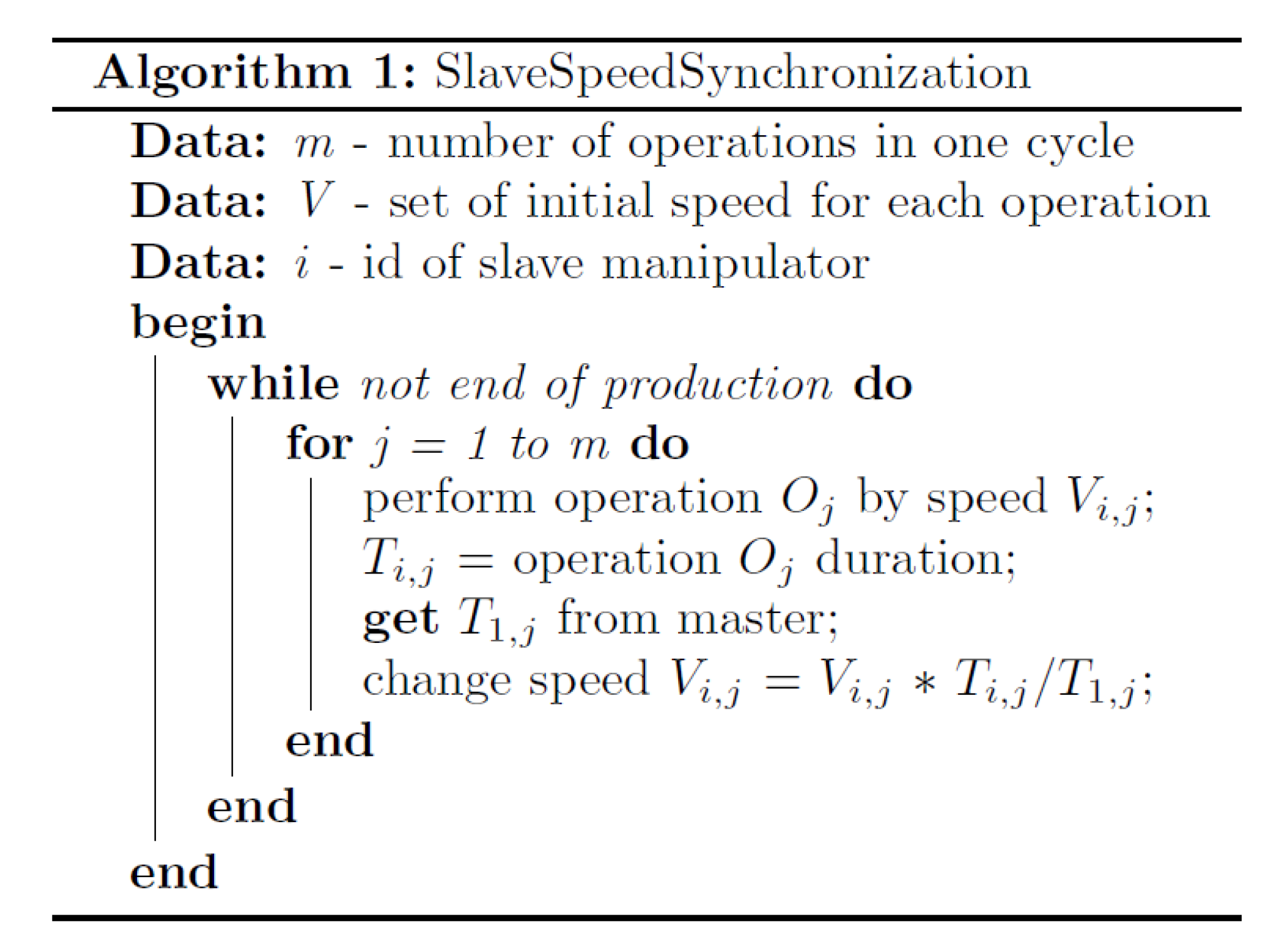
3.1. Basic Synchronization Algorithm
The elemental analysis results in the basic synchronization algorithm, which is the same for each slave manipulator
MSi; its structure is depicted in
Figure 2.
As is later mentioned in
Section 4.1., the main disadvantage of the proposed algorithm is low reaction speed to changes in master or slave behavior. This is contrary to the requirement R08 from
Figure 1. Every change of master manipulator
M1 (or slave manipulator
MSi) activity is captured immediately so the synchronization coefficient
Ki,j is evaluated. This leads to the adjustment of endpoint movement speed
Vi,j of each slave manipulator
MSi. However, the adjusted endpoint movement speed
Vi,j is actually used during movement of the slave manipulator
MSi in the next production cycle.
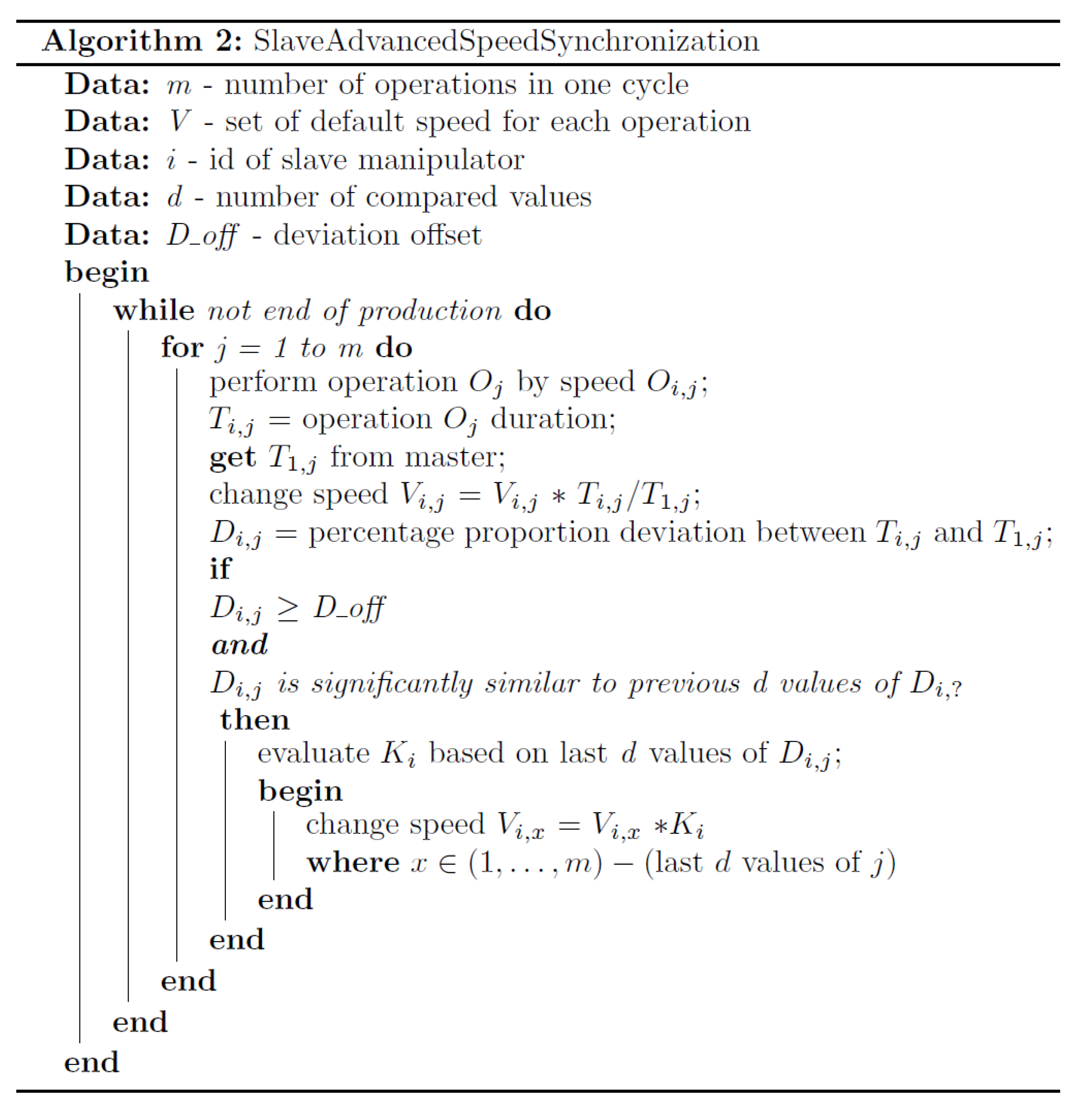
3.2. Advanced Synchronization Algorithm
If the master manipulator
M1 (or slave manipulator
MSi) activity change has a global character (endpoint movement speed increasing/decreasing), then it is possible to indicate this change using variable
D. This variable represents the percentage proportion deviations among operation durations of master and slave manipulators, where
is calculated based on Equation (2).
The variable D is calculated in each step of the algorithm, but is only usable from the second production cycle. The first production cycle has diverse values of deviations Di,j, from first step of second cycle, Di,j within defined tolerance represent synchronized state. Every change of Di,j values exceeding the limit can be considered as a desynchronization indicator.
If two (or another specified number
d) differences
Di,j-(d−1) …
Di,j of consecutive operations
Oj-(d−1) …
Oj are sufficiently similar based on the similarity threshold
Dratio_limit (Equation (3))
and this difference exceeds the given threshold of change
Dlimit (Equation (4)),
then advanced synchronization coefficient
Ki (Equation (5)) is applied to all other operation execution speeds
Vi,j, except the actual operation (which is already adjusted in this step) and previous
d − 1 values (which were adjusted in previous
d − 1 steps).
Both algorithms were designed for (theoretically) endless repetition of production cycle. The above-mentioned previous values of the current Di,j in the initial steps of every cycle are based on an endless loop of variable j. For example, in the case of 10 operations in one production cycle, after the initialization cycle, the previous two elements V2,j (endpoint speed of slave manipulator M2) to element V2,1 are V2,10 and V2,9.
The synchronization algorithm with a feedforward reaction to the general change of the master manipulator
M1 (or slave manipulators
MSi) endpoint movement speed is identical for every slave manipulator
MSi and is depicted in
Figure 3.
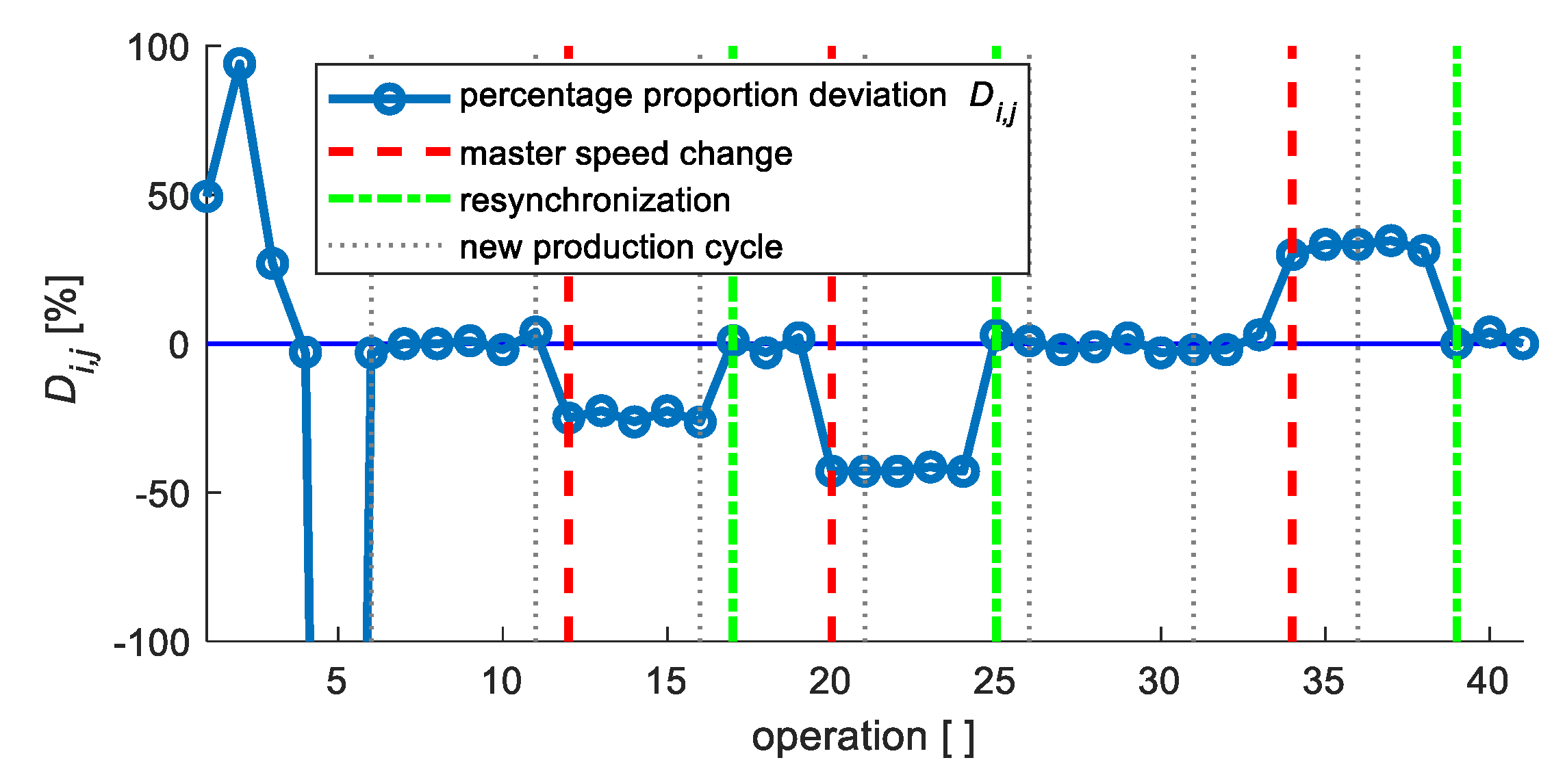
4. Validation of the Proposed Solution
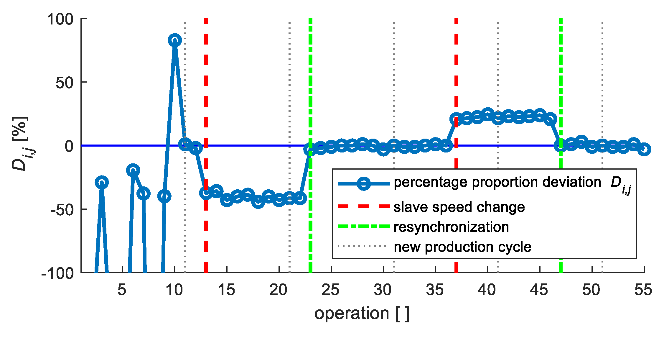
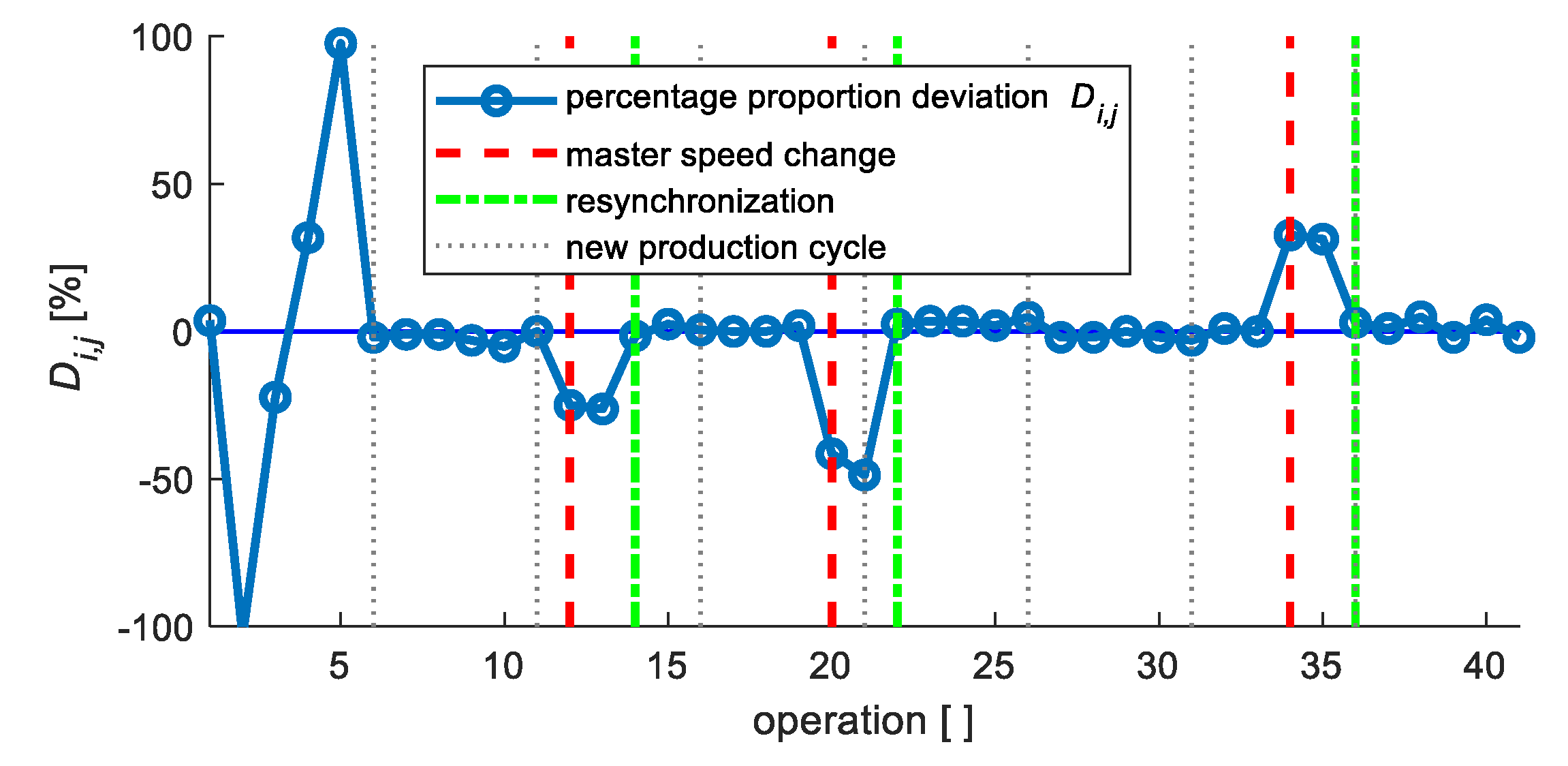
The proposed solution was experimentally validated in two phases. In the first phase, the algorithms were implemented as scripts in the MATLAB software environment. To evaluate the efficiency of the algorithms, monitoring of the percentage proportion deviation Di,j (Equation (2)) was used. The aim of the solution was to reach a Di,j value as close as possible to zero. The synchronization state was indicated by a value close to zero within the specified tolerance. In contrast, a value exceeding the limit can be considered as a desynchronization indicator.
In the second phase, the designed algorithms were implemented in the native language of real robotic manipulators in a specific multi-robotic cell.
4.1. Simulation Validation of Solution Functionality
The functionality of the proposed solution was validated by simulations using the MATLAB software tool (R2018a, The MathWorks, Inc., Natic, MA, USA, 2018). The designed algorithms were processed by a script and the results were represented in graphical form.
Duration times
T1,j of master manipulator
M1 operations were simulated as generated random values of a vector in the range of 0–5000 ms. Each value
T1,j was modified during its processing with a random element from the range (−2%, +2%), that represents a stochastic process part. Because the synchronization algorithm for all slave manipulators
MSi is identical, the case with one slave manipulator
MSi, where
i = 2, was validated by simulation. Operation durations
Ti,j of this slave manipulator were simulated on the basis of Equation (6).
In Equation (6) the variable Si,j ϵ S = {S2,1, …, Sn,m} represents the path length of operation Oj performed by manipulator MSi. An idealized kinematic model of a manipulator with omission of the non-linear character of robot arm movement in acceleration and deceleration was used for simulation validation purposes. Elements of the S set were generated as random values of a vector in the range of 0–1000 mm in the simulation validation process. The default endpoint movement speed Vi,j of the slave manipulator was set to 200 mm/s. In processing of each operation duration Ti,j, an additional modification with the stochastic part from the interval (−2%, +2%) of Ti,j was also used.
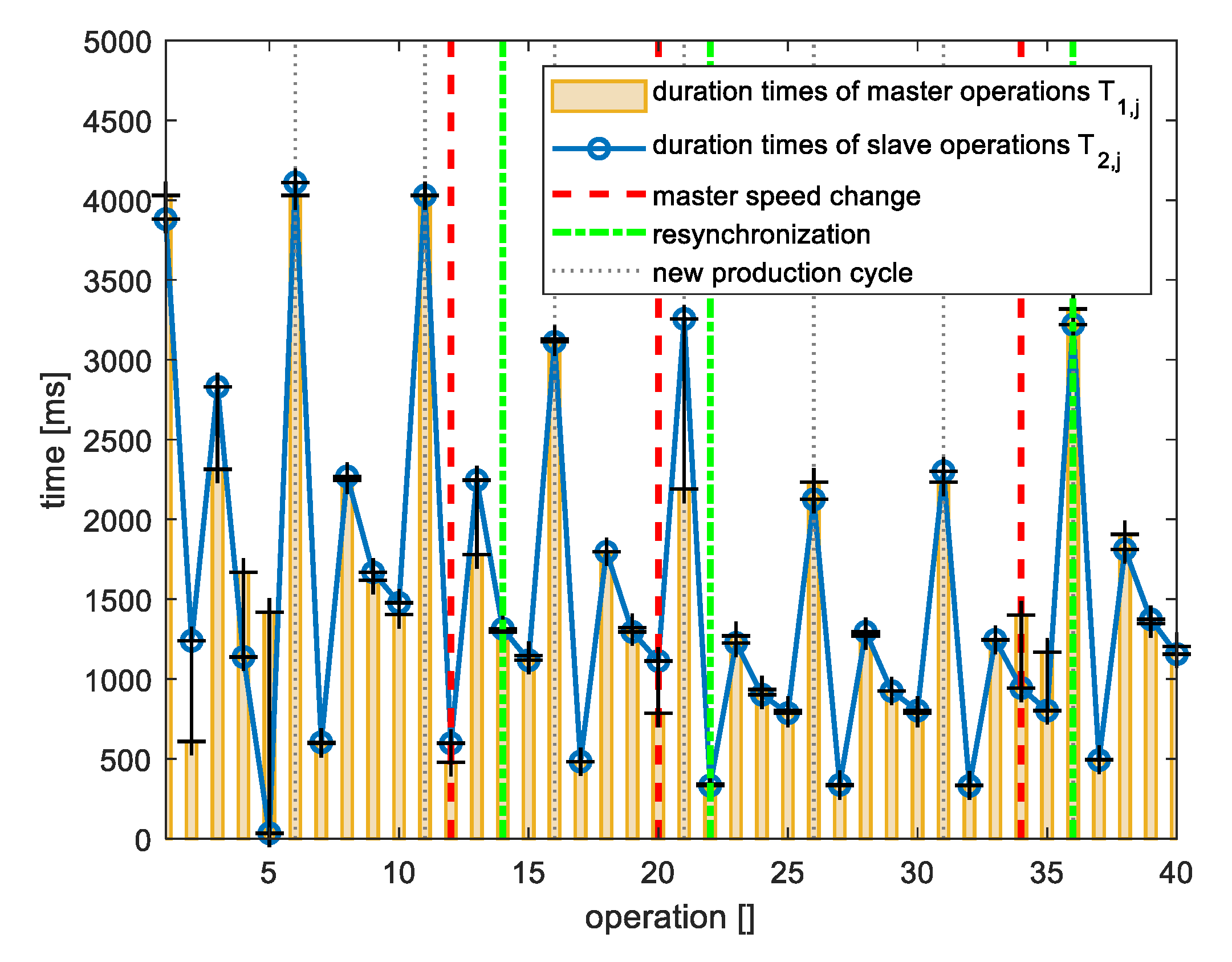
4.1.1. Experiment 1a—Master Speed Change, Basic Algorithm
Simulation Experiment 1a includes:
eight production cycles of production cell
five operations in every production cycle (m = 5)
change of master manipulator M1 operation speed
- ○
in the 3rd production cycle by +20% of current speed value
- ○
in the 4th production cycle by +30% of current speed value
- ○
in the 7th production cycle by −50% of current speed value
master manipulator M1 speed change in different time of production cycle
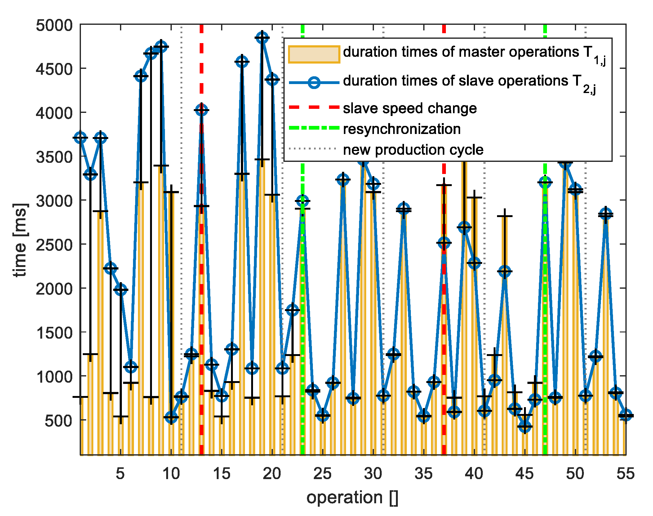
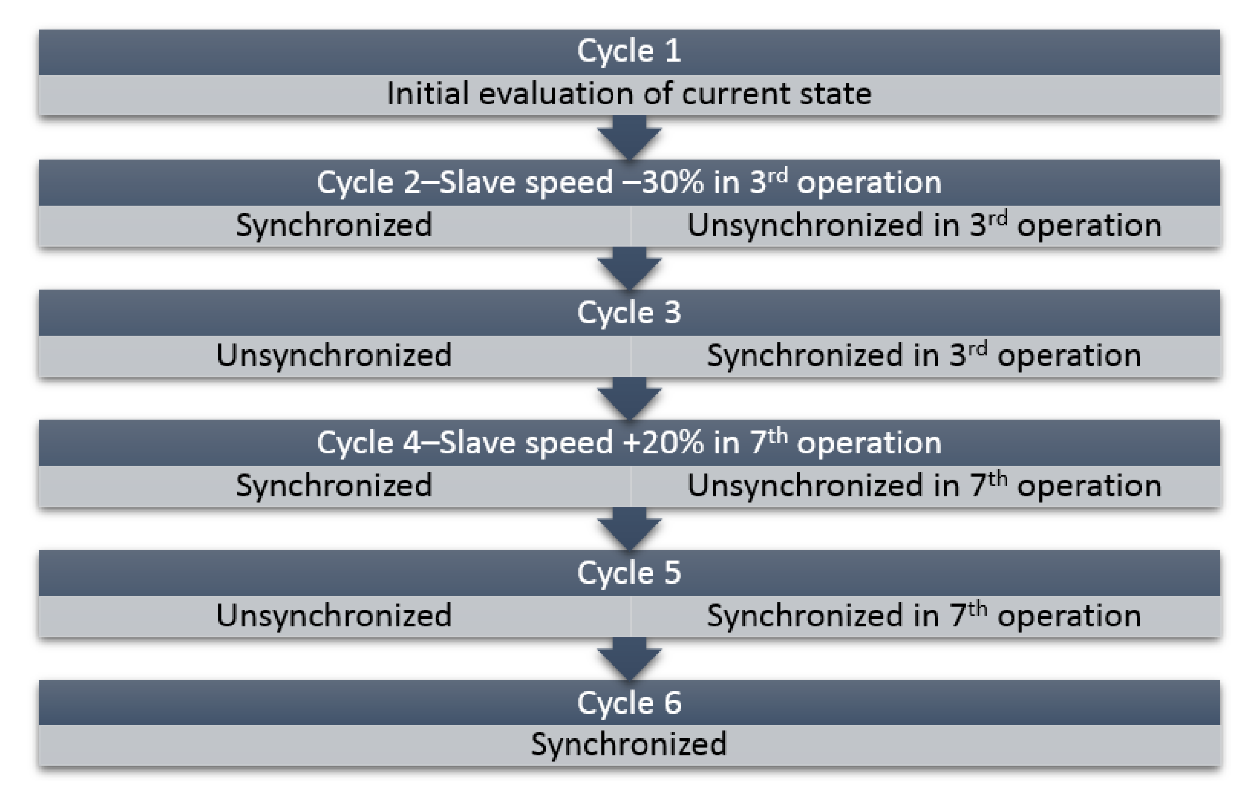
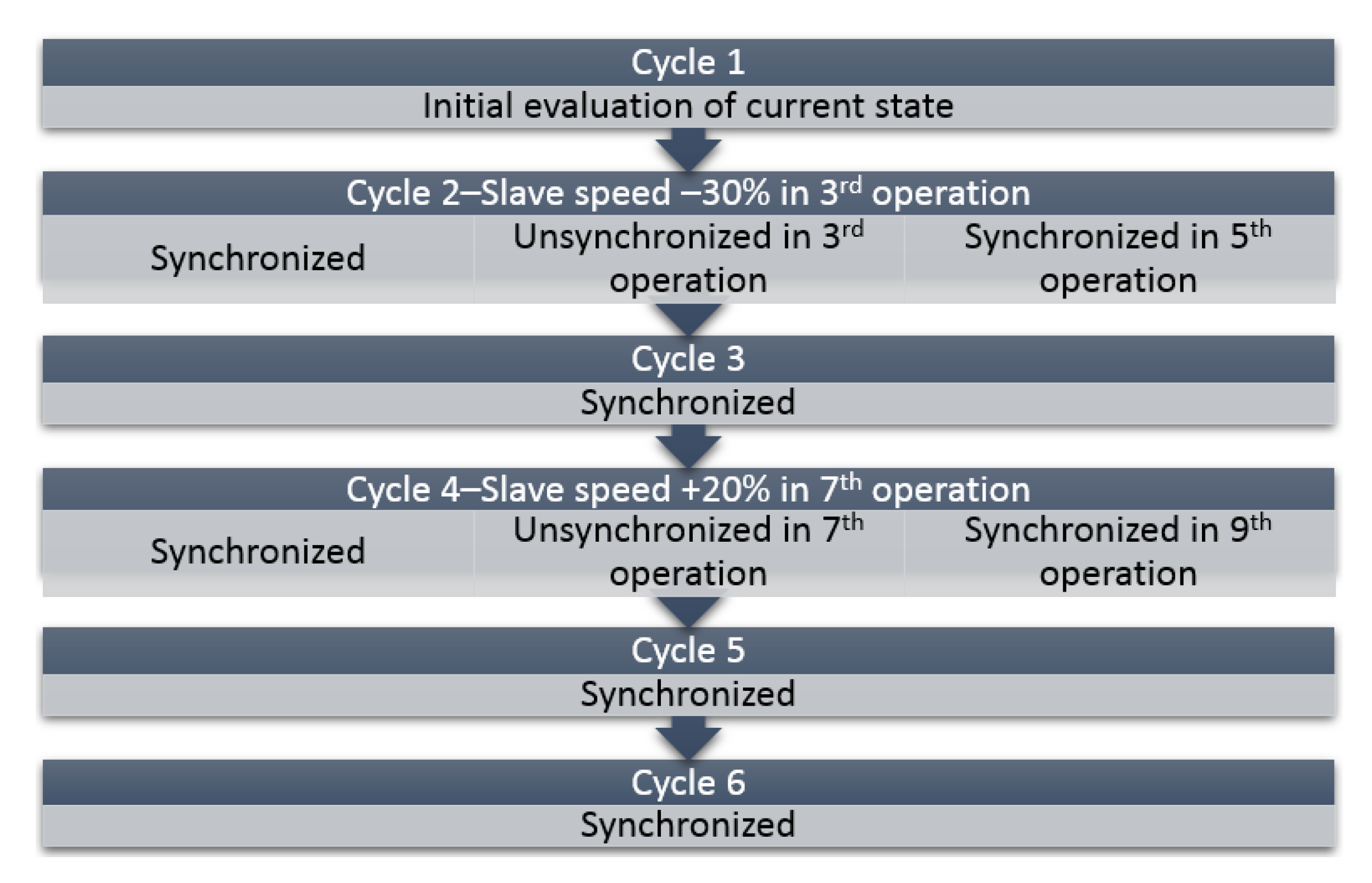
4.1.2. Experiment 2a—Slave Speed Change, Basic Algorithm
Simulation Experiment 2a includes:
six production cycles of production cell
10 operations in every production cycle (m = 10)
change of slave manipulator MS2 operation speed
- ○
in the 2nd production cycle by −30% of current speed value
- ○
in the 4th production cycle by +30% of current speed value
slave manipulator MS2 speed change in different time of production cycle
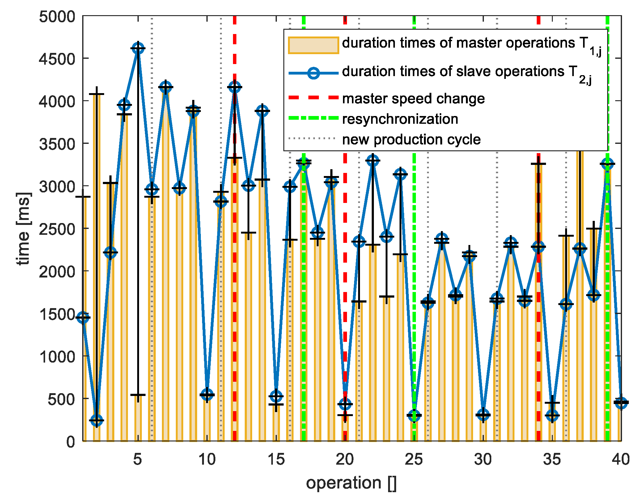
4.1.3. Summary of Experiment 1a and Experiment 2a
The obtained simulation results of the experiment with master speed change are depicted in
Figure 4 and
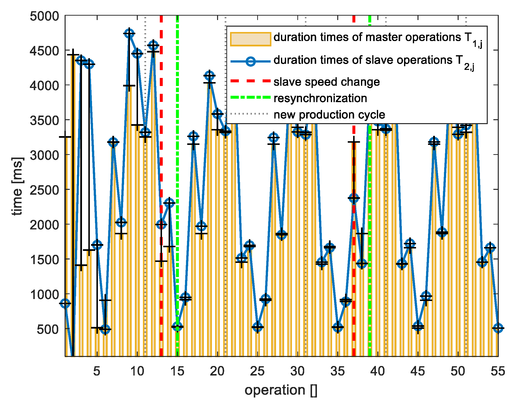
Figure 5. Results of both experiments, experiment with master speed change and the experiment with slave speed change, is aggregated in
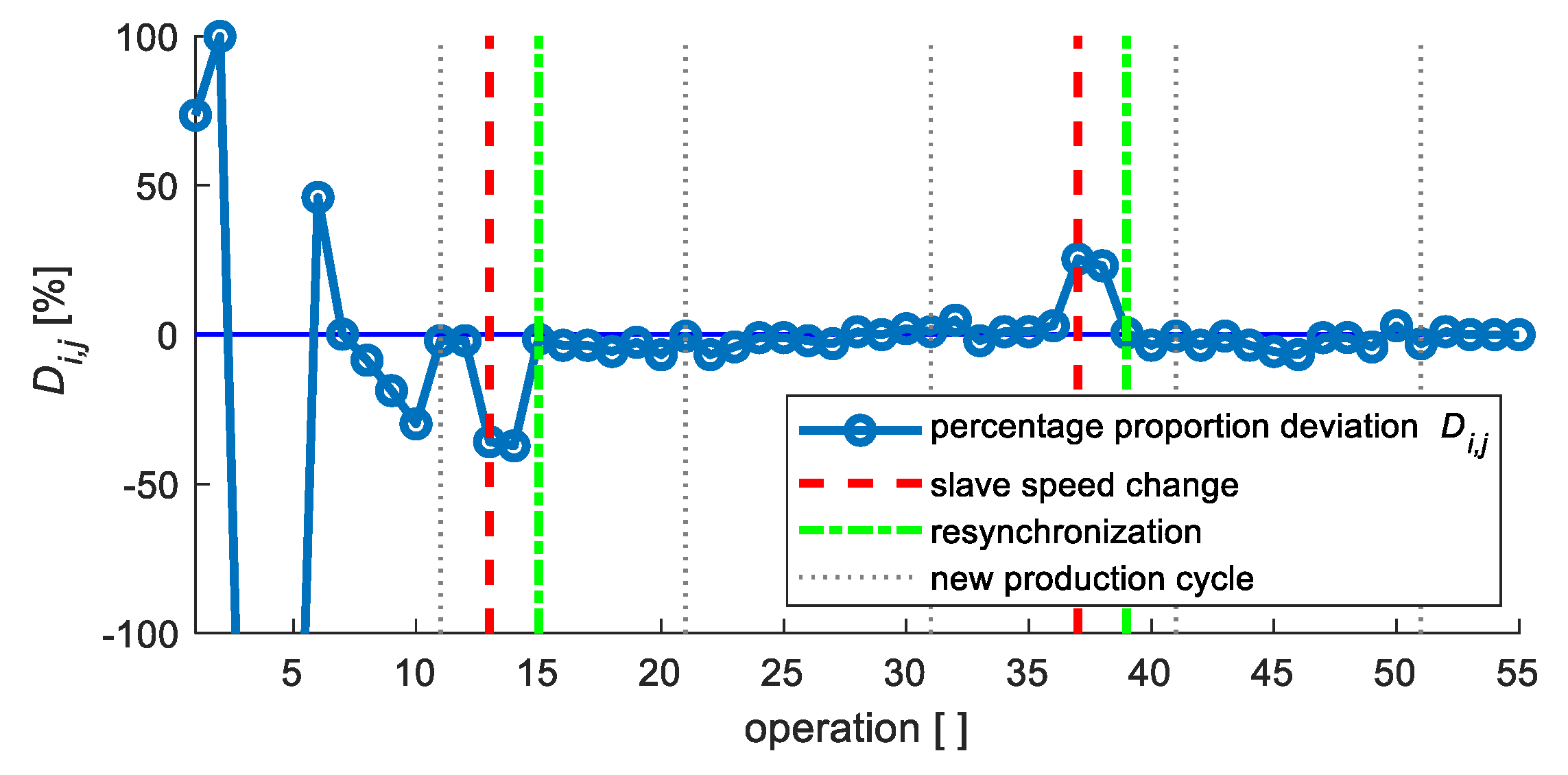
Figure 6, and the results of the experiment with slave speed change in
Figure 7 and
Figure 8.
Figure 9 also presents results of both experiments, experiment with master speed change and the experiment with slave speed change.
4.1.4. Experiment 1b—Master Speed Change, Advanced Algorithm
The case with a 10% limit for the error of the difference between operation duration performed by master and slave manipulators and a 15% significance limit for the similarity of two successive deviations Di,j and Di,j + 1 was validated via simulation.
In simulation Experiment 1b, equal parameters of the whole simulated system were used as in simulation Experiment 1a, with the addition of the feedforward synchronization feature to the synchronization algorithm.
4.1.5. Experiment 2b—Slave Speed Change, Advanced Algorithm
Identical parameters of the whole system as in simulation Experiment 2a were used in simulation Experiment 2b. The synchronization algorithm was supplemented by a feedforward synchronization function.
4.1.6. Summary of Experiment 1b and Experiment 2b
The simulation results of the experiment with a change of master manipulator speed are depicted in
Figure 10 and
Figure 11. Results of the experiment with a change of slave manipulator speed are shown in
Figure 12,
Figure 13 and
Figure 14. Both experiments results, where an advanced synchronization algorithm was used, are aggregated in
Figure 12 and
Figure 15. These results prove that the proposed algorithm can identify a global change of speed of the master element (Experiment 2a) and also of the slave element (Experiment 2b). Most importantly, the algorithm is able to modify the speed of the slave element (elements) feedforward unlike in the case of the standard algorithm. Based on monitoring the operation duration of master and slave manipulators (
Figure 10 and
Figure 13), and according to evaluation of percentage proportion deviations (
Figure 11 and
Figure 14), it is clear that the algorithm ensured the time-synchronized movement in the 3rd step of the production cycle from such a change. This resynchronized activity is indicated by a minimized absolute value of percentage proportion deviation
Di,j in the two operations after this change.
4.2. Implementation of the Proposed Solution and Discussion
The functionality of the designed algorithms was tested in the final phase on real robot manipulators in a multi-robotic cell. The algorithms were processed in the native language of each robotic manipulator controller using its built-in standard functions.
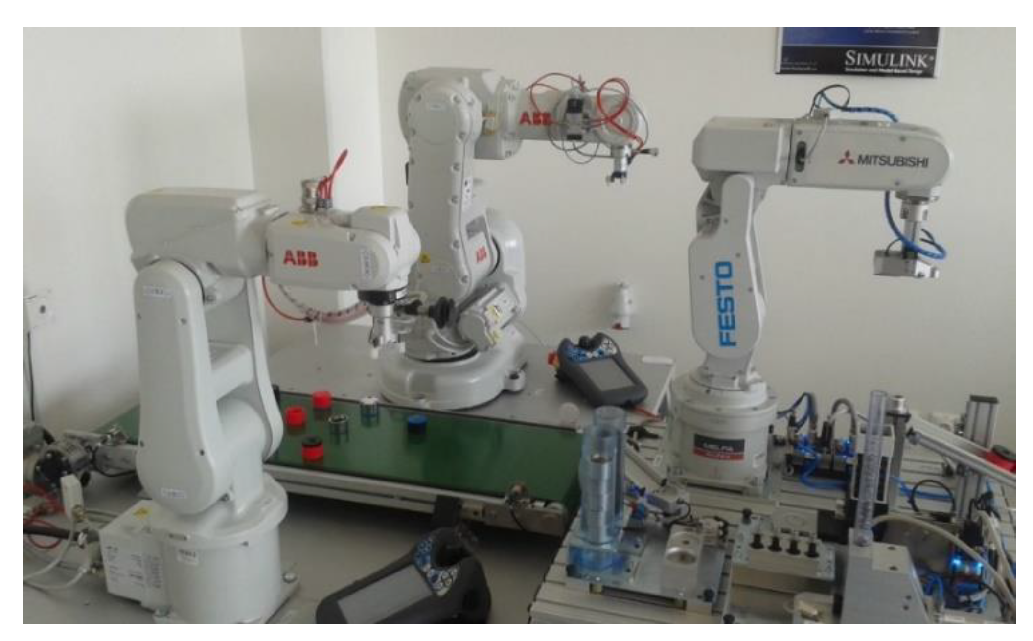
The model robotic cell, used for the purposes of this paper, contains a heterogeneous triplet of robotic manipulators as shown in
Figure 16.
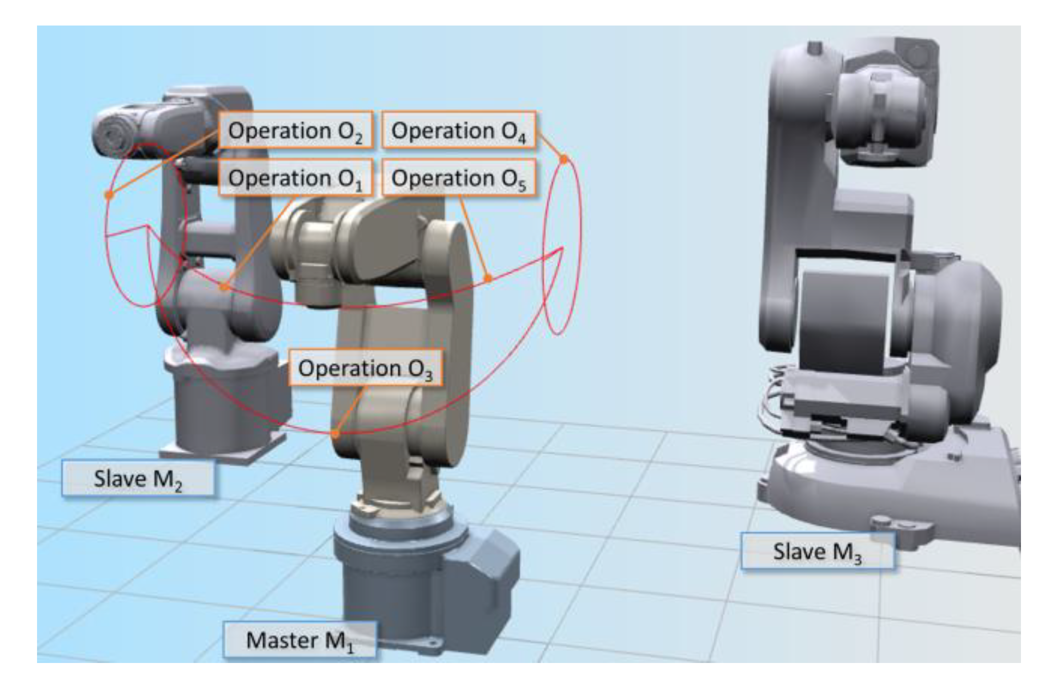
One production cycle consists of five operations (
m = 5), and mainly contains instructions for circular interpolation movement in combination with linear interpolation movement. The whole production cycle is schematically shown in
Figure 17.
The organizational structure of this robotic cell control was realized as master–slave [
24,
25] without an external control element. The master object (master manipulator) chosen was a Mitsubishi Melfa RV-2FB-D robot with the Mitsubishi CR750-D control system [
26]. Robots ABB IRB 120 and ABB IRB 140, with IRC5 Compact control systems, were the child objects-slaves [
27]. A personal computer was considered an element of the slave group and provided visualization of the cell activity synchronization process. Configurations of every cell element are listed in
Table 1 and
Table 2. The TCP/IP channel provided communication among cell elements on the basis of socket exchange [
25,
28].
Confirmed coordination of operations control among robotic manipulators and unconfirmed communication between master and monitoring computer were used in the cell. Confirmed coordination means that after every operation is executed by the master element, a terminating message is sent to the slave side and the master element waits for a confirmation message. The next operation can only be initiated after receiving a confirmation message from the slave object. Unconfirmed communication in this case involves simply receiving messages about the synchronization process by the slave object, without sending any confirmation message to the master object [
25].
4.2.1. Master—Mitsubishi Melfa RV-2FB-D
In the case of the Mitsubishi CR750-D controller of the robotic manipulator Mitsubishi Melfa RV-2FB-D, the algorithm application was implemented in MELFA BASIC V language [
29]. Communication with the slave object was realized through the initiated TCP/IP channel (
Box 1).
Box 1. Communication initiation in MELFA BASIC V.
Open “COM7:” As#1 ‘IRB120 IP:192.168.1.120 port 10007
Open “COM8:” As#2 ‘IRB140 IP:192.168.1.140 port 10008
Open “COM6:” As#3 ‘PC IP:192.168.1.111 port 10006
A duration time of each operation was evaluated and this information was, after the message was received on the completion of each operation by all slave objects, sent in a defined format to these slave objects. This message was also a confirmation message that enabled the beginning of the next operation execution. The operation duration time evaluated by the master object (
Time) was measured in milliseconds. All of the obtained information was also sent to the visualization part of the application for further processing (
Box 2).
Box 2. Socket communication in MELFA BASIC V.
M_TIMER(1) = 0
{Operation instructions}
Time = M_TIMER(1)
Input #1,msg1$
Input #2,msg2$
Print #1,STR$(Operation_ID)+”:”+STR$(Time)
Print #3,”1-”+STR$(ID)+”:”+STR$(Time)
Print #3,”2-”+msg1$
Print #3,”3-”+msg2$
4.2.2. Slaves—ABB IRB 120/IRB 140
In the case of controllers ABB IRC5 Compact of robotic manipulators ABB IRB 120 and ABB IRB 140, the designed algorithms were implemented in RAPID language, which is the native language for ABB robot programming [
30]. Communication with master object was realized through the activated TCP/IP channel (
Box 3).
Box 3. Communication initiation in RAPID.
VAR socketdev client_socket;
SocketCreate client_socket;
SocketConnect client_socket,”192.168.1.20”,10007\Time:=5;
Each operation time duration was measured in each production cycle and, on the basis of the decoded information from the received socket sent by the master object (custom function
DecodeSocket), an actual speed for that operation was modified (custom function
ChangeSpeed). This modified speed was used for the presently evaluated operation in the next production cycle. If there is a need for feedforward form of reaction on speed change then a custom function
FeedforwardChange can be used (
Box 4).
Box 4. Socket communication in RAPID.
ClkStart clock1;
{Operation instructions}
ClkStop clock1;
n_time: = ClkRead(clock1);
SocketSend client_socket\Str: = ValToStr(op_id)+”:”+ValToStr(n_time
× 1000);
SocketReceive client_socket\Str: = s_receive_string\Time:= 10;
DecodeSocket;
ChangeSpeed;
[FeedforwardChange];
The function DecodeSocket provided information extraction from received socket (s_receive_string). This information consisted of operation identifier (op_id) and time of its duration (t_in) for the master object. Built-in functions of RAPID language for string processing StrPart, StrMatch, StrLen and StrToVal were used.
The custom function
ChangeSpeed provided the modification of speed used for the current operation execution in the array of all operations speeds. These speed values were used in the next production cycle. A numerical array was also used for storing percentage proportion deviations between durations of the operation performed by master and slave objects. This array can be optionally used for feedforward synchronization. The operation duration time evaluated by a slave object (
n_time) was measured in seconds (
Box 5).
Box 5. The function ChangeSpeed in RAPID.
speed{op_id}:= speed{op_id} × (n_time × 1000/t_in);
diff{op_id}:= (1-(n_time × 1000/t_in)) × 100;
The optional function
FeedforwardChange provides an evaluation of whether the indicator of current operation change is supraliminal and, at the same time, is sufficiently similar to the indicator of the previous operation change. In the case of positive evaluation, all records in the operation speed array, except those of the current and previous operation, are modified utilizing a dynamically modified array of operation indexes (
Box 6).
Box 6. The feedforward function in RAPID.
op_indx:= [1, …, n]; diff_ratio:=Abs(1-(diff{op_indx{n}}/diff{op_indx{1}}))
× 100;
IF (Abs(diff{op_indx{1}})>diff_limit) AND
(diff_ratio<diff_ratio_limit) THEN
k:=1-(((diff{op_indx{1}}+diff{op_indx{n})/2)/100);
FOR i FROM 2 TO n-1 DO
speed{op_indx{i}}:=speed{op_indx{i}} × k;
ENDFOR
ENDIF
Rotate_op_indx_left;
4.2.3. Visualization—MATLAB Application
For the visualization of the robotic cell behavior, any development tool supporting functionalities for sockets processing can be used. In this case, the visualization part of application was implemented using the MATLAB software tool since it was already used for simulation validation of the proposed solution. The capability of MATLAB to access existing system Java classes to be used in the MATLAB workspace [
31,
32,
33,
34] was utilized in this application part. The communication with the master object was realized through the activated TCP/IP channel (
Box 7).
Box 7. Communication initiation in MATLAB.
import java.net.Socket
import java.io.×
input_socket = java.net.Socket();
input_socket.connect(java.net.InetSocketAddress(server,port));
The received message from the master object consisted of cell object identifier (
station), operation identifier (
index), and operation duration (
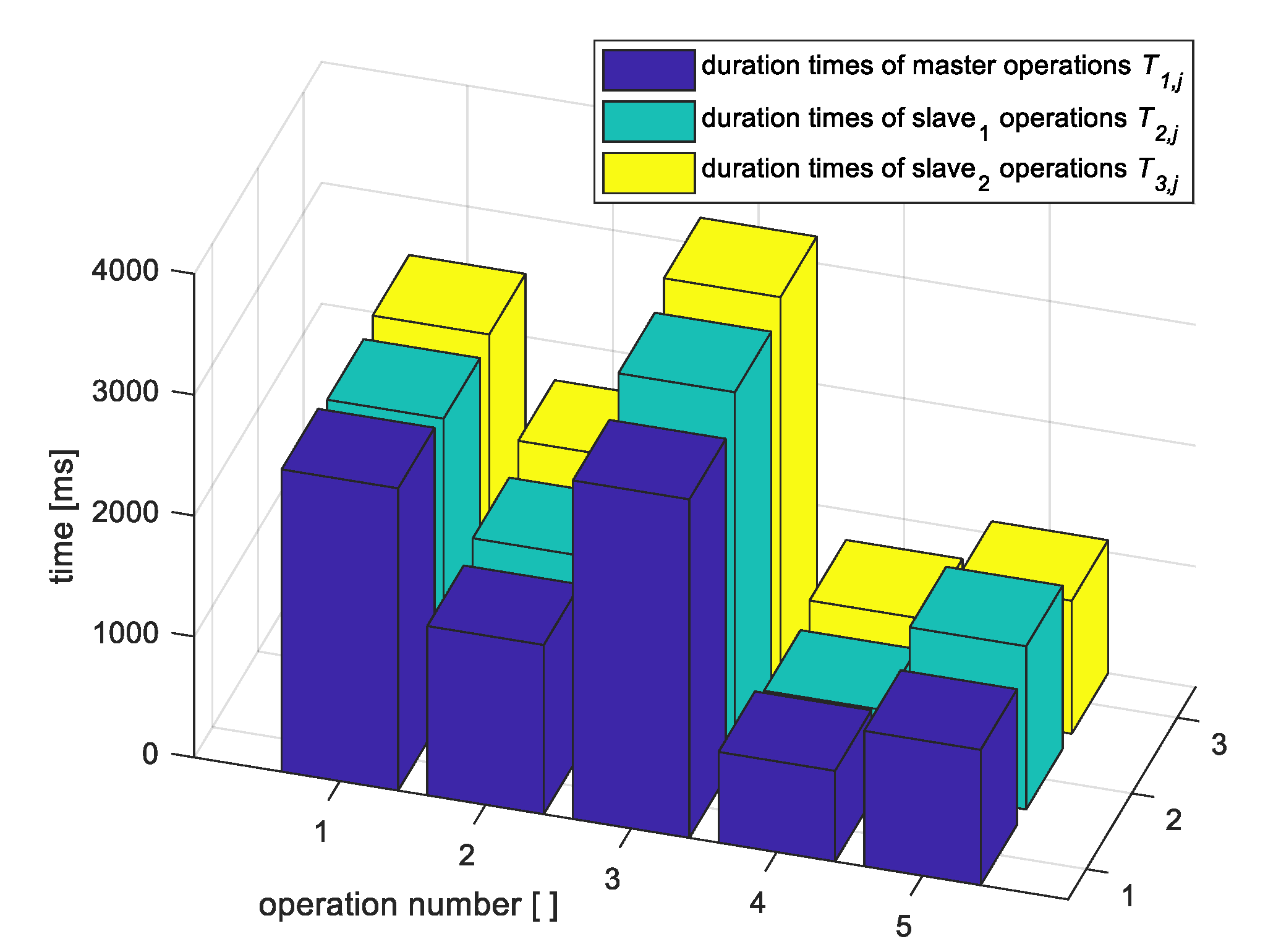
value). After decoding, the message was used as a data source for graphical representation (3D bar graph) of the production process in the robotic cell, as shown in
Figure 18,
Figure 19 and
Figure 20 (
Box 8).
Box 8. Socket communication in MATLAB.
input =
BufferedReader(InputStreamReader(input_socket.getInputStream));
message = char(input.readLine());
{graph(station)}.ZData(index) = value;
The graph in
Figure 18 was updated after each operation. Information on the operation duration of all participating executive elements was collected and subsequently distributed by the master manipulator.
4.2.4. Implementation Results
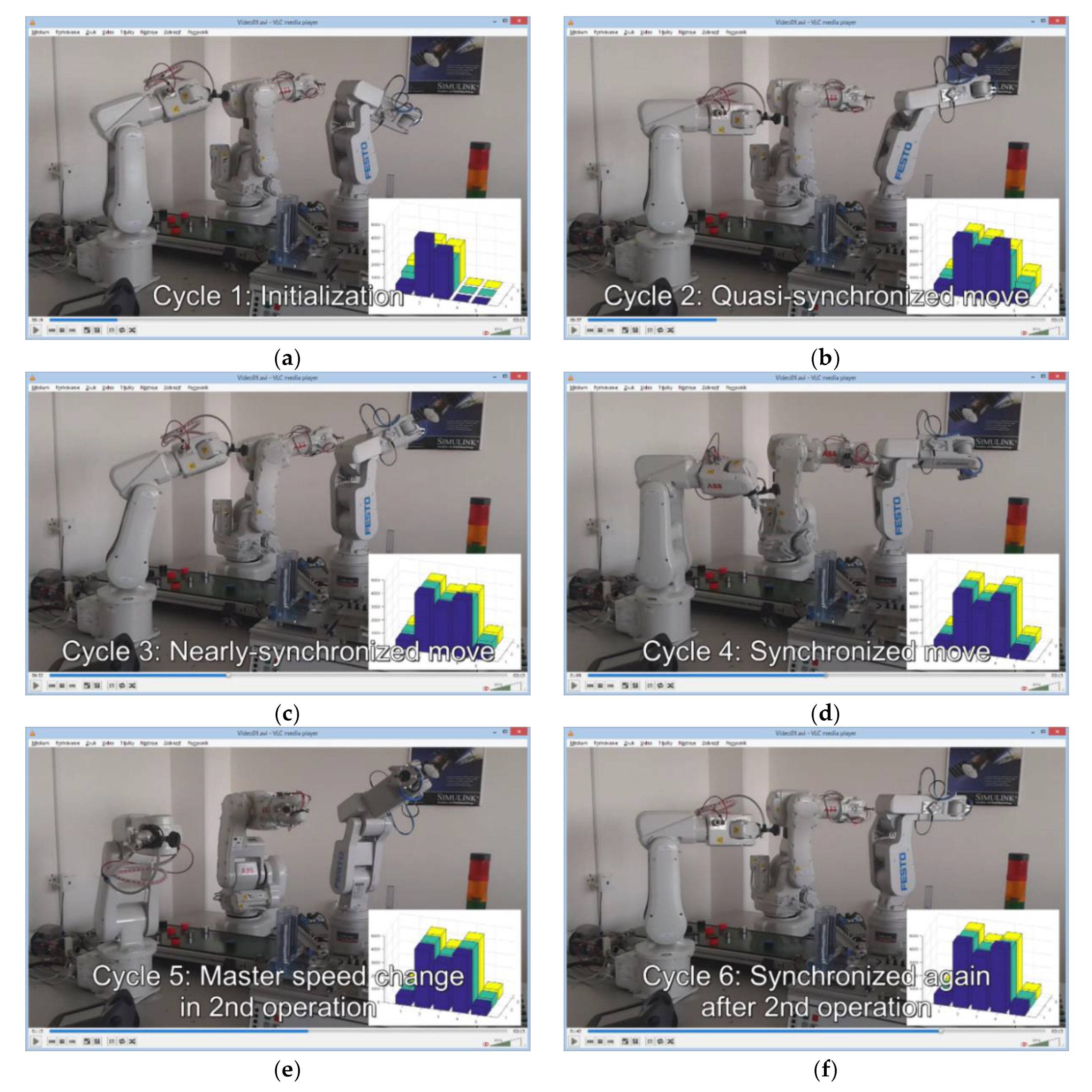
Implementation results are represented based on the visualization part of the application. The operation durations of all cell elements during the production process with the implemented basic algorithm without feedforward synchronization are depicted in
Figure 19.
The change of endpoint movement speed of the master manipulator occurred in this case during operation number two in production cycle five (
Figure 19e). The production cell activities were resynchronized after the 2nd operation in the next production cycle (
Figure 19f).
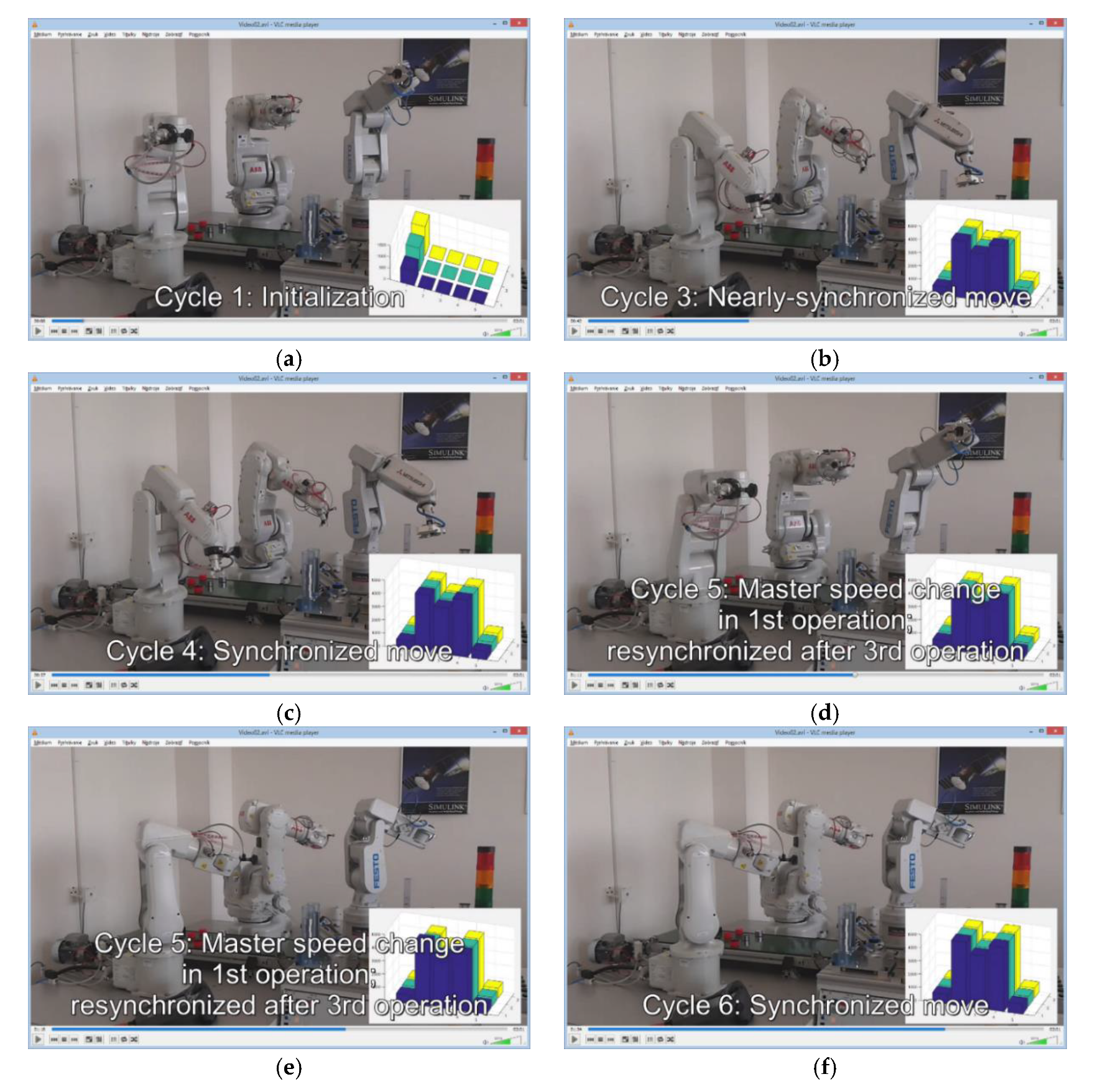
In the case of the advanced algorithm with feedforward synchronization implementation (
Figure 20), the movement speed change of the master manipulator endpoint occurred in operation one during production cycle five (
Figure 20d). The feedforward effect ensured production cell activities were resynchronized in the next two operations in the same production cycle (
Figure 20e).
On the basis of the obtained results depicted in
Figure 19 and
Figure 20, it is clear that the proposed and simulation-validated algorithm for the synchronization of the movement speeds of manipulators (representing endpoint movement speeds) grouped in heterogeneous robotic work cells is functional and applicable. The deviations in achieved operation duration times of master and slave robotic manipulators in the initial production cycles (
Figure 19b,c and
Figure 20b) are noticeable. These are caused by non-linear characteristics of the movement of robot arms (acceleration, deceleration), and because operations two and four are composed of several movements of different types (linear, circular). However, this disproportion is fully eliminated by dynamic speed correction of the slave manipulators during subsequent cycles.
In the case of basic non-feedforward synchronization, the system reaction to the endpoint movement speed change of the master manipulator was as expected. The process was resynchronized in the next production cycle in the same operation, where the change occurred.
The results also indicate that the reaction of slave manipulators to the global change of the master manipulator speed with the use of feedforward synchronization persists in real conditions for an additional cycle step (
Figure 20e) than is presented in
Section 3.1 for the simulated system with idealized conditions. The reason for this difference is that the master manipulator speed change occurred during operation execution. The percentage proportion deviation among these operation durations (between master and each slave) is thus different from the percentage proportion deviation among durations of the next operation that is completely performed at the changed speed.
5. Conclusions
In this study, an algorithms for the time synchronization of operations performed by a heterogeneous set of robotic manipulators grouped into a production cell was proposed, validated, and implemented. The organizational structure of this robotic cell control was realized as master–slave without an external control element. Communication in the cell was provided by a TCP/IP channel via sockets. The proposed problem solution requires minimal computational power due to an empirically oriented approach. We relied on our wide empirical knowledge and experiences in process algorithmizing, as well as on various previously implemented tasks in the field of robotics or the modeling and visualization of processes. This approach enabled the solution to be processed directly by the control unit of each participating element of the robotic cell with utilization of standard instructions in their native language. The main aim was to dynamically adapt the movement speed of slave manipulator endpoints to the master manipulator activity. Therefore, the algorithms ensure the defined milestones of the production cycle of each robotic manipulator in the cell are attained at the same time, while all operations may include various sets of different motion or manipulation instructions.
The proposed solution also includes an advanced feedforward form of operation synchronization which responds to changes in the operating cycle of the master manipulator or slave manipulators more effectively. The main difference between the two proposed algorithms is the number of unsynchronized operations performed after the change of the master or the slave behavior. In the basic algorithm case, after desynchronization, the operations of one cycle are performed unsynchronized. In contrast, the advanced algorithm ensures resynchronization after a defined number (in our case two) of asynchronously performed operations.
The application of the solution proposal is supplemented with a visualization part created using MATLAB software for technical computing. This application illustrates each intervention of the synchronization algorithms, and enables more efficient monitoring and evaluation of the multi-robotic cell activity with a focus on the synchronization process. This application part complements the validation of the functionality of the designed solution.
Finally, it can be stated that all requirements were successfully met and our solution for synchronization of the heterogeneous multi-robotic cell with emphasis on low computing power is functional and feasible.
Our goal in the future is to continue to develop this idea based on current trends in industrial automation [
35]. There is a possibility in master–slave architecture to distribute more process or control information among elements, e.g., target position or movement type together with operation duration as used in our solution. Visualization, as an important aspect of the production of tomorrow, can be realized using virtual or augmented reality [
35].


