Article

Dynamic Tensile Testing of Needle-Punched Nonwoven Fabrics

by
Francisca Martínez-Hergueta
1,*,
Antonio Pellegrino
2,
Álvaro Ridruejo
3,
Nik Petrinic
2,
Carlos González
3,4 and
Javier LLorca
3,4
1
Institute for Infrastructure and Environment, School of Engineering, The University of Edinburgh, William Rankine Building, Edinburgh EH9 3FG, UK
2
Department of Engineering Science, University of Oxford, Parks Road, Oxford OX1 3PJ, UK
3
Department of Materials Science, Universidad Politécnica de Madrid, E. T. S. de Ingenieros de Caminos, 28040 Madrid, Spain
4
IMDEA Materials Institute, Calle Eric Kandel 2, 28906 Getafe, Madrid, Spain
*
Author to whom correspondence should be addressed.
Appl. Sci. 2020, 10(15), 5081; https://doi.org/10.3390/app10155081
Submission received: 26 June 2020 / Revised: 17 July 2020 / Accepted: 21 July 2020 / Published: 23 July 2020
(This article belongs to the Special Issue Armour and Protection Systems)

Abstract

:
The tensile testing of a needle-punched nonwoven fabric is presented. A high-sensitivity Split-Hopkinson Tensile Bar device was specifically designed for this purpose. The strain gauge measurements were combined with high-speed photography and Digital Image Correlation to analyse the deformation micromechanisms at high strain rates. The experimental set-up allowed to determine the wave propagation velocity of the as-received nonwove fabric, the evolution of the strain field with deformation and the wave interaction inside the fabric. The deformation was accommodated by the same micromechanisms observed during quasi-static tensile testing and ballistic impact, which comprised fibre straightening, rotation and sliding. Heterogeneous strain fields were developed in the nonwoven fabric as a result of the non-linear pseudoplastic response of the fabric and the internal dissipation due to the frictional deformation micromechanisms, preventing the propagation of high magnitude strain waves into the specimen. Additionally, the output forces were analysed to determine the influence of high-strain rates in the mechanical response of the nonwoven fabric, finding an increment of the stiffness for low applied strains under dynamic loading. These findings provide the basis to develop strain-rate dependent constitutive models to predict wave propagation in needle-punched nonwoven fabrics when subjected to impact loads.

Graphical Abstract

1. Introduction

Dry fabrics based on high strength fibres such as Kevlar and Dyneema are conventionally used for soft body armour due to their high energy absorption capacity against ballistic impact [1]. These materials present a very low bending stiffness due to the lack of resin, resulting in lightweight flexible textiles for personal protection [2]. Their membrane response results in a large amount of energy absorption due to in-plane deformation [3]. They can be divided into woven and nonwoven fabrics depending on the disposition of the fibres in the fabric. Needle-punched nonwoven fabrics present a lower stiffness and strength (as well as processing cost) than their woven counterparts, but possess a higher deformability and excellent ballistic performance against small calibres and shrapnel [4]. It is possible to find in the literature multiple applications for protective barriers based on nonwoven fabrics for soft body armour and the transport industry [5,6,7,8,9,10]; nevertheless, the biggest improvement in ballistic performance is obtained when nonwoven fabrics are combined with traditional barriers based on dry woven fabrics, as cushion layers, or metal plates with a negligible increment of the total areal weight of the target [4,11,12,13]. It is possible to find detailed studies focused on the quasi-static response [14,15] and the ballistic performance of the material [10,16,17,18,19]; nevertheless, there is still a lack of knowledge regarding the effect of high strain rates in its mechanical properties. For instance, a detailed dynamic characterisation is required to understand the differences in the wave propagation (scattering and dissipation) between a continuous medium and the actual network structure [20]. Moreover, further research is needed to determine the dynamic mechanical properties and developed sound, physically-based strain rate dependent constitutive models with superior predictive capability than the current phenomenological approaches that tuned the stiffness and strength of the fabric to fit the ballistic limit of the layer [21].
The dynamic characterisation of structural materials is usually accomplished with a Split-Hopkinson Bar (SHB) device, that procures the stress–strain constitutive relationships for high strain rates [22]; however, measuring the dynamic tensile response of nonwoven fabrics is a challenging task that presents considerable technical difficulties. For instance: (i) the mechanical characterisation of low impedance fabrics results in a low response in the transmission bar, difficult to register by conventional strain gauges; (ii) their inherent low wave speed makes the transit time much longer than in metallic materials and an equilibrated stress state may not be reached during dynamic deformation [23,24]. The validity and the accuracy of the experimental data thus need to be examined in detail; (iii) the nonwoven fabrics present high ductility and strain to failure, hence, the time duration of the pulse needs to be long enough to ensure large deformations are applied; (iv) the minimum representative sample size to characterise the fibre network is given by the fibre length of several millimeters, which is orders of magnitude higher than the size of constituents of conventional composite materials, in the order of micrometres [25]. This fact makes necessary the use of large gauge lengths that contain at least one Representative Volume Element (RVE) to reproduce the characteristic mechanical response of the fabric [14,26]. As a result, the maximum strains and strain rates reachable during the SHB experiment become lower. The transit time also increases, hindering the possibility to attain the force equilibrium state in the bars [27].
To overcome these issues, several solutions have been reported in the literature, mostly applied to the dynamic characterisation of engineering foams and tissues. The response of soft materials is usually characterised with high sensitivity transmission bars such us hollow metal tubes [28,29,30], low impedance Magnesium bars [31,32] or polymer bars [33,34,35]. A higher sensitivity can be obtained by embedded piezoelectric pressure transducers, able to provide forces three orders of magnitude lower than conventional SHB transmission bars [36,37,38]. Large applied strains are also achievable when increasing the duration of the stress pulse, either employing long strikers [39] or electromagnetic loading [40]. Despite all previous developments, it is possible to find in the literature experimental campaigns where the equilibrium stress state in the bars was not attained [38,41]. In those cases, analysis is usually complemented by high-speed photography and Digital Image Correlation to evaluate the heterogeneous strain fields and interpret the registered forces [42].
This study aims to determine the dynamic response of needle-punched nonwoven fabrics subjected to in-plane tensile loads, with special emphasis on the evolution of wave propagation. A high-sensitivity Split-Hopkinson Tensile Bar device is specifically designed for this purpose. Strain gauge measurements are combined with high-speed photography and Digital Image Correlation to analyse the deformation micromechanisms at high strain rates. The experimental set-up allows to determine the wave propagation velocity, the evolution of the strain field with deformation and the wave interaction inside the fabric. Local strains and output forces are afterwards combined to estimate the strain rate dependency of the stiffness of the material. This investigation provides the basis to develop algorithms to predict the wave propagation phenomenon of needle-punched nonwoven fabrics.

2. Material

The material selected for this study was a needle-punched nonwoven fabric with commercial name Fraglight NW201 (DSM) comprised of a web of ultrahigh molecular weight polyethylene Dyneema SK75 fibres of ≈60 mm in length. The nominal areal density was ≈190 to 220 g/m 2 and the thickness varied from ≈1.5 to 2 mm. The fabric was composed by a random network of curved fibres that transfer the load through the knots generated during the needle punching process [43]. The manufacturing process introduced two orthogonal principal material orientations denominated the roll or machine (MD) and transverse (TD) directions, inducing a higher fibre connectivity along the TD with larger volume fraction of entangled active fibres. The quasi-static in-plane tensile response and the ballistic performance of the material have been previously characterised, and the main deformation and failure mechanisms are briefly recalled in Section 4.1 for the sake of completion [15,19,44].

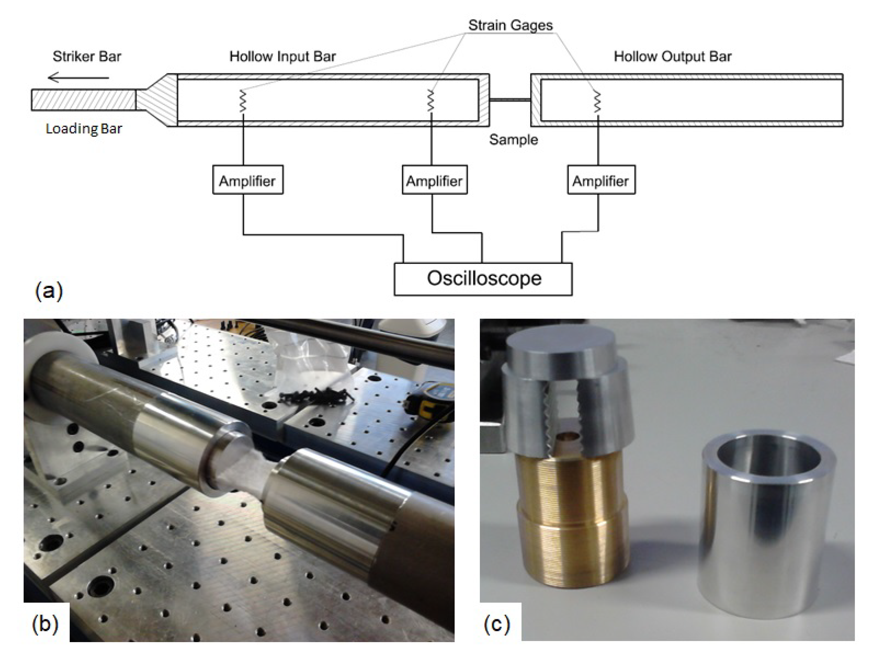
3. Experimental Techniques

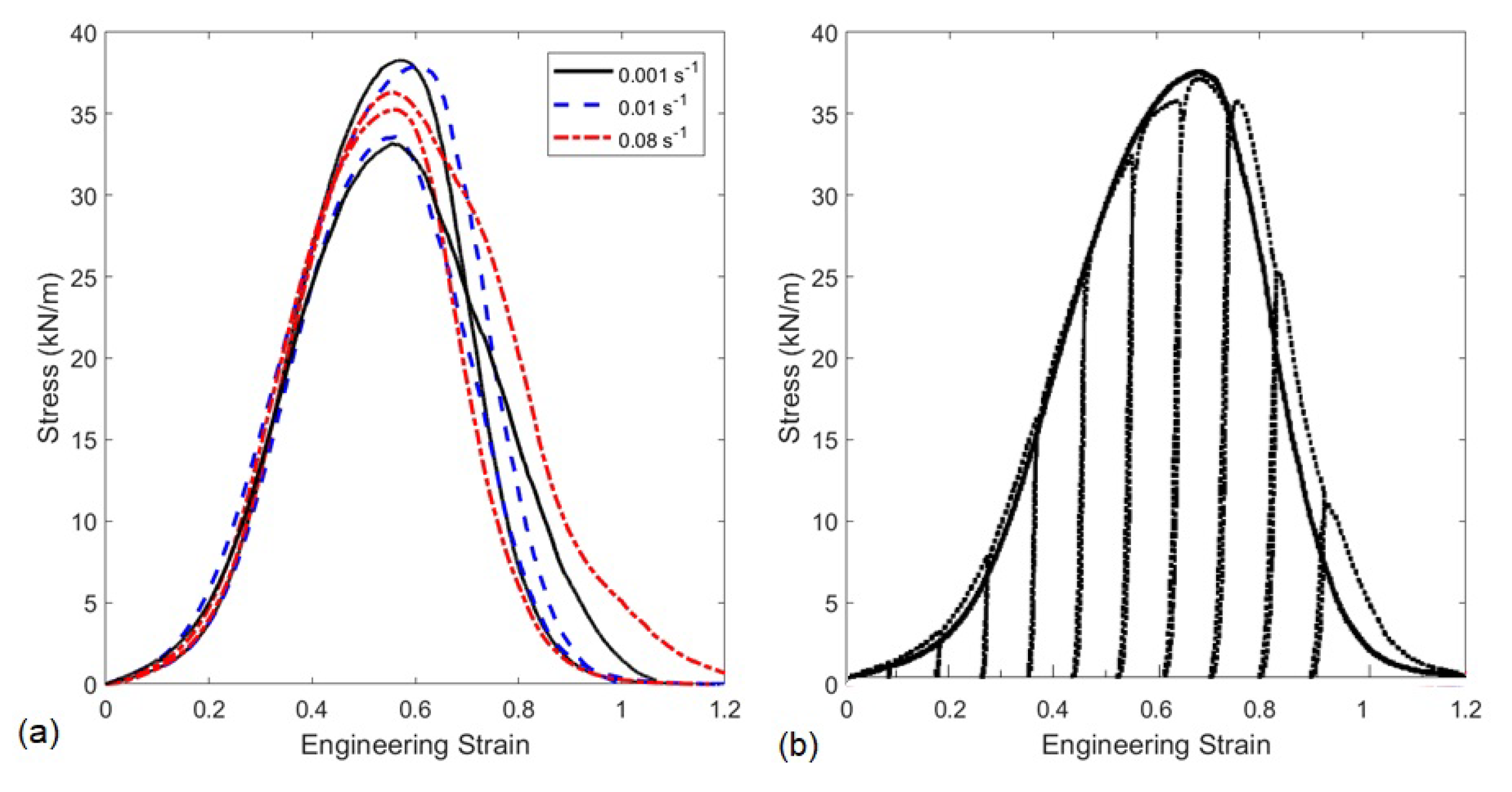
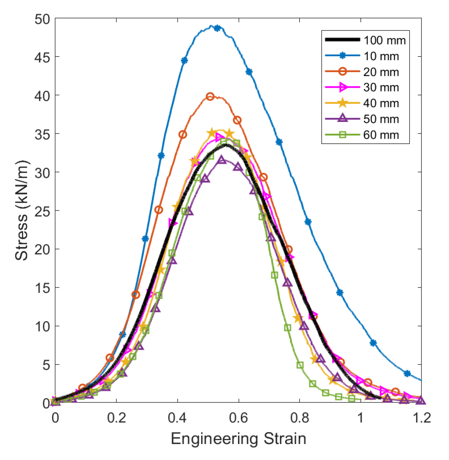
3.1. Quasi-Static Tensile Testing

Rectangular specimens of 35 mm in width (maximum width allowance for the current Split Hopkinson Bar) and gauge length varying from 10 to 60 mm were cut from the fabric roll with special scissors for high strength fibres. The specimens were subjected to in-plane unidirectional tensile deformation at the orientation transverse to the roll direction (TD), the stiffest direction of the nonwoven fabric. Two flat steel plates were used to clamp the fabric by means of frictional loads with a gripping length of 25 mm to avoid slippage. The quasi-static tests were carried out under stroke control at cross head speed of 1 mm/s with the actuator of a Zwick screw-driven testing frame. The load was recorded continuously with a 20 kN load cell together with the cross-head displacement of the testing frame. Additionally, a laser extensometer was used to acquire the displacement of the gauge section. Three test repetitions per gauge length were accomplished.

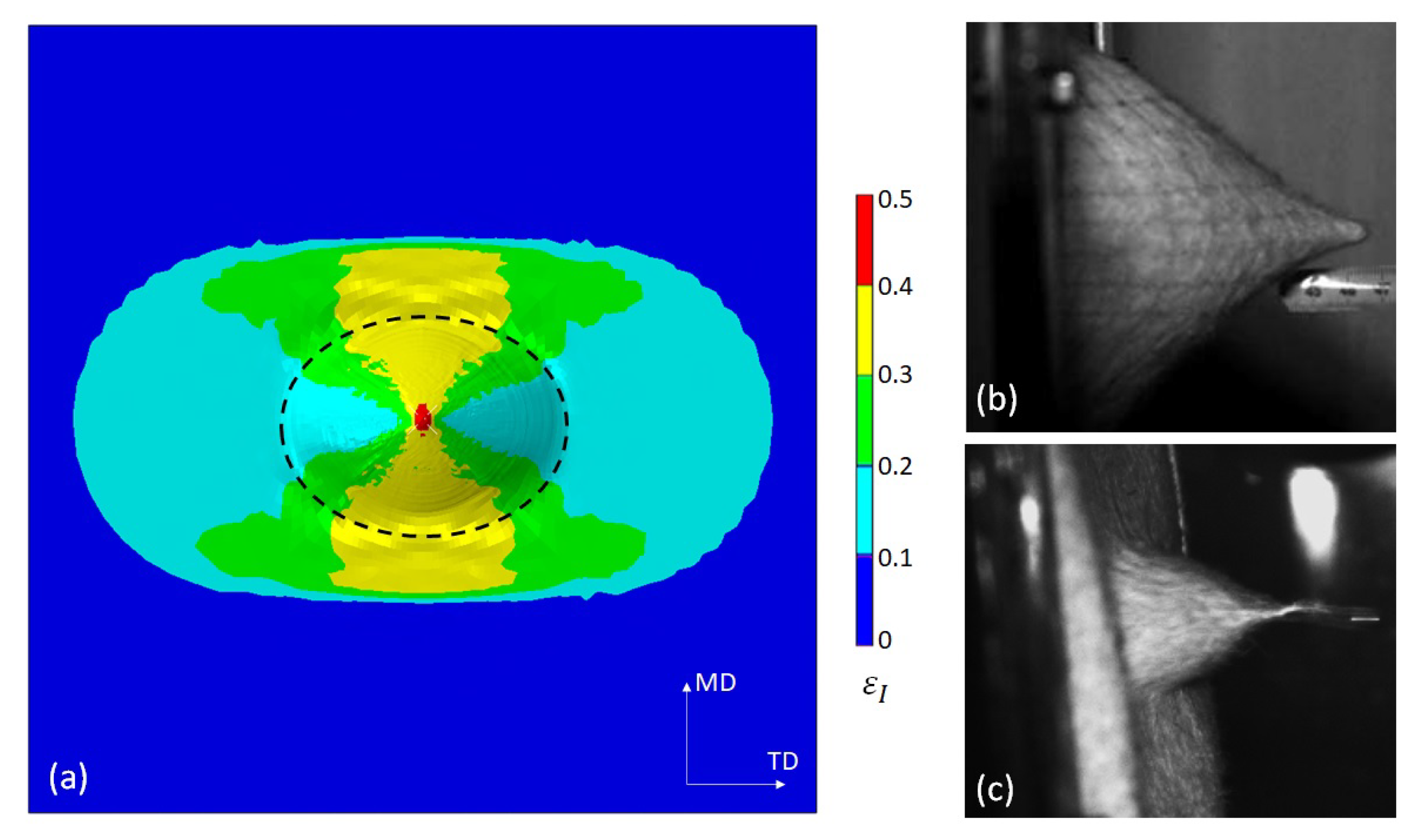
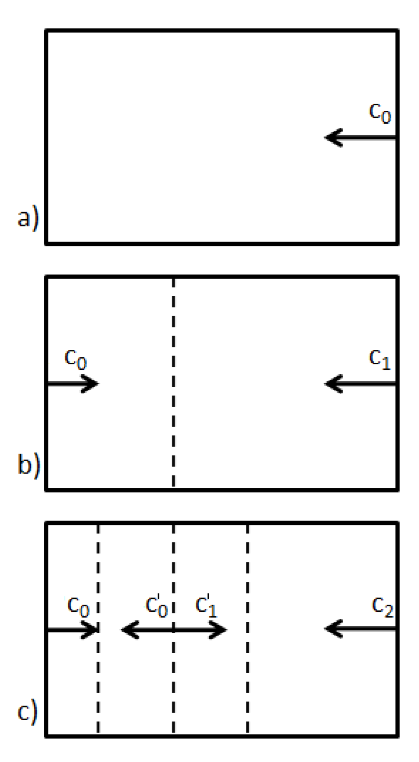
3.2. Dynamic Tensile Testing

The dynamic testing of the nonwoven fabric was conducted on a Split-Hopkinson Tensile Bar (SHTB) device specially designed for this project. The requirements were set at: (i) high sensitivity of the output bar to register the mechanical response of soft fabrics; (ii) long time duration of the stress pulse, to facilitate the force equilibrium between bar ends and increase the applied strain; and (iii) large gauge length to characterise the fibre network response and avoid the influence of the material constituents.
The present experimental set-up comprised of hollow input and output bars connected to a loading bar actuated by a striker; see Figure 1a. The loading bar was surrounded by a striker with a U shaped cross-section supported through brass railings to freely slide and strike the impact flange of the loading bar. The striker was fired by a hook connected to a pulling rod and piston propelled by a low-pressure chamber. The hook accelerated the striker towards the impact flange generating the stress pulse that propagated towards the loading and input bars. Further details of this SHTB equipment are available in [39]. For the current experiment, a titanium Ti-6Al-4V loading bar of 3.6 m in length and 20 mm diameter was used, surrounded by a titanium U shaped striker of 35 mm diameter and 2.5 m in length providing a pulse duration T 1 ms [45]. The input and output bars comprised of Aluminium 7075-T6 alloy hollow tubes of 50.8 mm outer diameter, 1.651 mm wall thickness and 2.7 m in length. A thread adaptor manufactured in steel was included to connect the loading and input bar. The fabric was gripped by conical clamps allowing a maximum specimen width of 35 mm, see Figure 1b. The gauge length of the specimens, equivalent to the distance between clamps, was set to 35 mm for all experiments to ensure the mechanical response was representative of the homogeneous macroscale. All the components of the grips were manufactured in Aluminium except the threads that were produced in brass to avoid welding during the loading process; see Figure 1c.
The input and output bars were instrumented with three strain gauges, as in Figure 1a. The amplifiers were used to accurately record the signal on the order of millivolts. All the signals were registered by a high frequency oscilloscope and were post-processed with a Matlab script. The main outcomes were the forces and the velocities of the bars and the average applied strain rate. The specimens were speckled with a random pattern and the full-field displacement measurements were carried out via high-speed photography, employing an high-speed Kirana camera operated at 50,000 fps. Acquisition rate was limited by the time duration of the experiment. 2D Digital Image Correlation analysis was performed using the commercial software Vic2D.

4. Results and Discussion

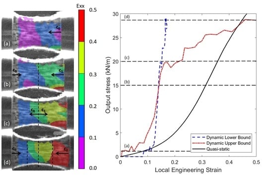
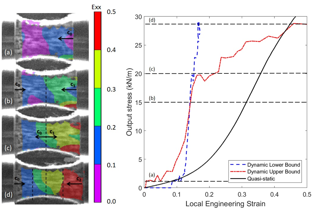
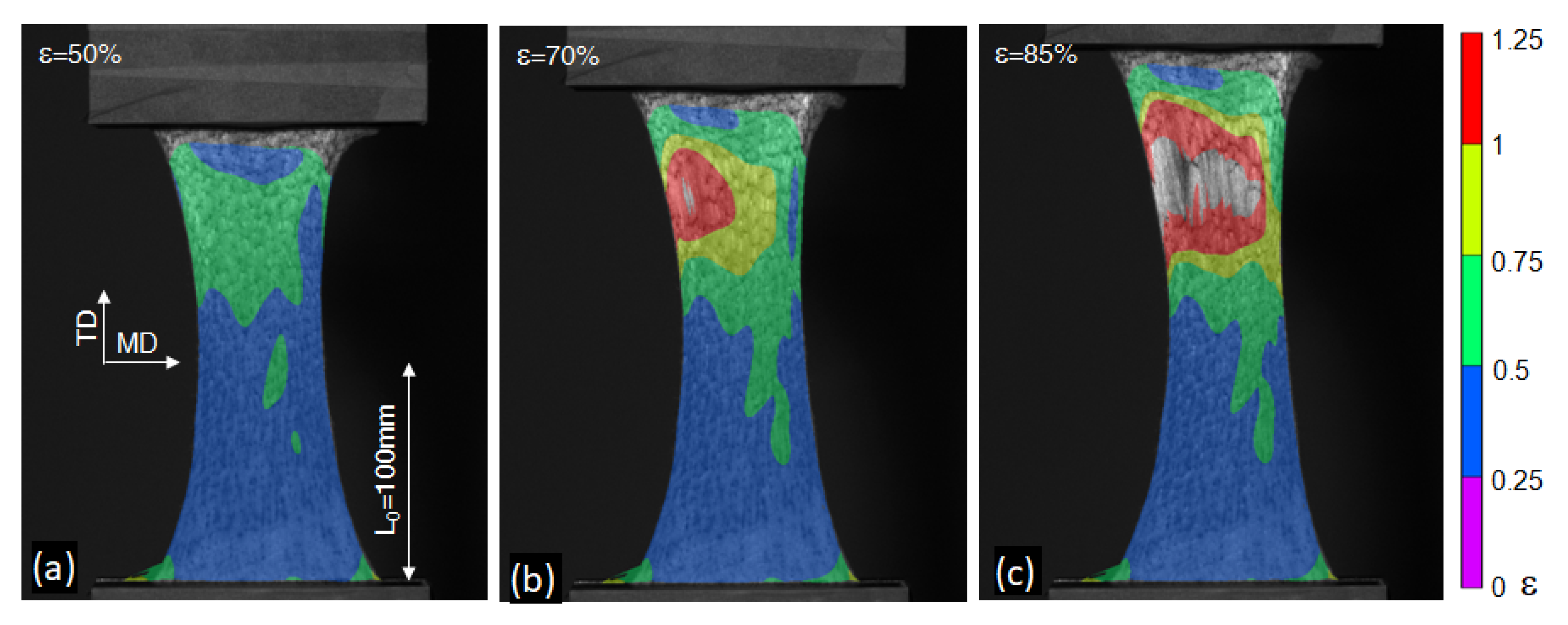
4.1. Mechanical Response and Deformation Micromechanisms

The quasi-static in-plane mechanical response of the material was dominated by the rotation and realignment of fibres towards the loading direction; see Figure 2. The stiffness of the material was directly proportional to the fibre orientation distribution function (ODF) resulting in an equivalent increment of tangent stiffness with strain; see Figure 3a. The fabric also presented a pseudo-plastic response with irrecoverable deformations even at very low strains; see Figure 3b. A large scattering in mechanical properties such as nominal strength was registered due to the stochastic nature of the fibre network; however, similar stiffness and strength values were found for quasi-static strain rates ranging from 0.001 to 0.08 s 1 [15]. The strain distribution was fairly homogeneous in the central region of the specimens before the maximum load. Afterwards, the failure of the material was triggered, inducing large strain gradients due to damage localisation; see Figure 4. The final failure of the material occurred due to fibre sliding and pull-out from the entanglement points, resulting in a high energy dissipation and a gradual reduction of load carrying capacity. The energy dissipation mechanisms at a smaller scale were quantitatively characterised by individual pull-out tests. A predominance of frictional fibre slippage was found, with a significant amount of dissipated internal energy during the loading process, two times larger in magnitude than the elastic energy stored by individual Dyneema fibres upon uniaxial stretching. Further details of this characterisation are available in [15].
The same deformation mechanisms appeared during ballistic impact. A longitudinal tensile wave was propagated through the fabric, and the material within the wave front dissipated energy through in-plane deformation. As a result of the dissimilar fibre connectivity along material directions, different wave propagation velocities appeared generating an elliptical wave front for the longitudinal and transverse waves; see Figure 5a. The main deformation micromechanisms were characterised such as radial uncurling, rotation and sliding of the active fibres towards the impact point. The tensile wave was followed by a slower transverse wave forming a cone of deformed material, see dashed line in Figure 5a and the experimental deflection in Figure 5b. A higher deformation was localised at the impact point, resulting in a steep strain gradient. Local fabric tearing and fibre pull-out was registered at the impact point for velocities above the ballistic limit; see Figure 5c. A numerical model was developed to predict the ballistic performance of the layers. Although the model captured the ballistic limit and the failure mechanisms for different fibre ODFs, it overestimated the energy absorption above the penetration threshold as a result of inaccuracies when modelling the wave propagation phenomenon. Further details are available in [19,21].

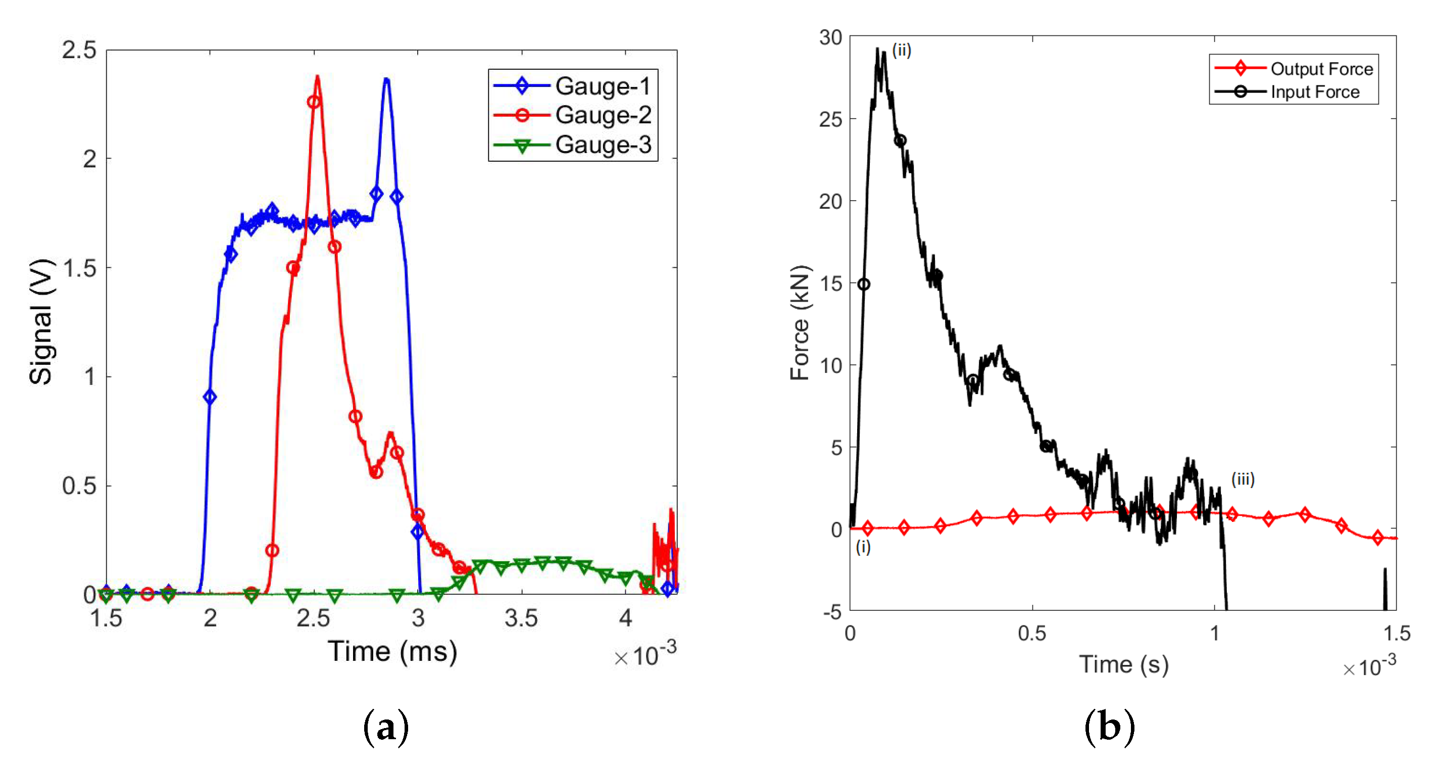
4.2. Gauge Sensitivity

A parametric study of the representative dimensions of the specimen was carried out to determine the size of a RVE and the minimum gauge length for dynamic testing in SHTB. The specimens with varying gauge lengths were systematically tested, and representative nominal stress (force per fabric width) vs. engineering strain curves are showed in the Figure 6. The results were compared against the baseline characterisation previously conducted on full-size samples (100 × 100 mm 2 ) [14,15]. The mechanical response of very short specimens was distorted due to the parasitic fibre clamping between both grips. Influence of a biaxial loading condition should be also considered. As a result, the samples with gauge length lower than 30 mm possessed a higher strength and stiffness and presented a significant percentage of fibre breakage, identified by a rough stress-strain curve at the onset of damage, as opposed to the representative smooth baseline mechanical response. The tensile fibre breakage was not a dominant failure mode of needle-punched nonwoven fabrics subjected to in-plane tensile loads or ballistic impact [15,19], nevertheless, the influence of this mechanisms could be neglected for gauge dimensions larger than half the average fibre length (30 mm).

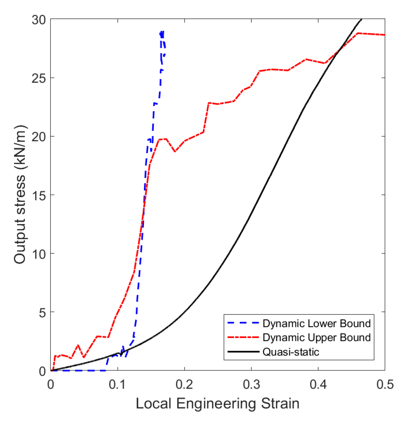
4.3. SHTB Validation

The dynamic tensile testing at high strain rates was conducted on the SHTB apparatus presented in Section 3.2. Figure 7a shows the raw voltage obtained from the strain gauges. The gauges 1 and 2 were installed on the input bar and the gauge 3 on the output bar. The generated stress pulse had an approximate trapezoidal shape with a duration of T 1 ms. A final peak was observed in the input signal (gauge 1) due to the overlap with the reflected wave generated at the interface between the input bar and clamp. The clamp, with higher impedance than the hollow tube, induced a reflected wave of same sign and lower magnitude, and transmitted to the specimen a tensile wave of same sign and higher magnitude [46].
The output bar was sensitive enough to monitor the response of the fabric registering a maximum force of ≈1 kN. Figure 7b shows the forces at the ends of the input and output bars. The time t = 0 ms indicates the onset of the stress propagation from the input grip. The response has been divided in three different stages: (i) onset of propagation of the tensile pulse, (ii) first reflection of the transmitted wave at the output bar interface and (iii) end of the tensile pulse. The wave propagation velocity of the nonwoven fabric was determined from the time lapse between the input and output forces (point (i) to (ii)), resulting in c 827.5 m/s, exceptionally slow compared to the wave propagation velocity of bulk semi-crystalline polyethylene (3800 m/s, [47]) or the theoretical wave propagation velocity of ultrahigh molecular weight polyethylene fibres (11,600 m/s, [48]), but in agreement with previous values registered for this fabric, ≈600 m/s [27]. The low wave propagation velocity and the large gauge length hindered the development of a theoretical force equilibrium state between bars. Input and output forces achieved similar force values (≈1 kN) after t = 0.7 ms; however, the input bar signal presented significant vibrational noise of same magnitude of the obtained force.
Digital Image Correlation (DIC) was employed to analyse the wave propagation in the material. The measurements were validated against the velocities monitored by the strain gauges, finding very good correlation; see Figure 8a. The maximum velocity at the input interface was registered as v i n p 14.5 m/s, with an output bar velocity virtually zero. Once the tensile pulse was exhausted, the input velocity decreased rapidly. The DIC contour plots registered a gradual transition of imposed velocities along the gauge length; see Figure 8b,c, and the wave end of the tensile pulse; see Figure 8d,e. The maximum input bar velocity was in agreement with the estimated analytical bound obtained by one-dimensional wave propagation theory considering the relationship between bar strains (or stresses) and particle velocity [45]:
σ = v c ρ
where σ stood for the incident pulse (0.11 GPa), and ρ and c stood for the density and the wave speed in the aluminium material, ρ = 2800 kg/m 3 and c = 5070 m/s, respectively. The resulting theoretical bar velocity was approximately v = 7.75 m/s. Due to the strong impedance mismatch between the aluminium tube and the specimen, nearly all the incident tensile wave was reflected at the specimen/bar interface with same magnitude and opposite sign, duplicating the particle velocity imposed at the input interface ( 14.5 2 v = 15.5 m/s).

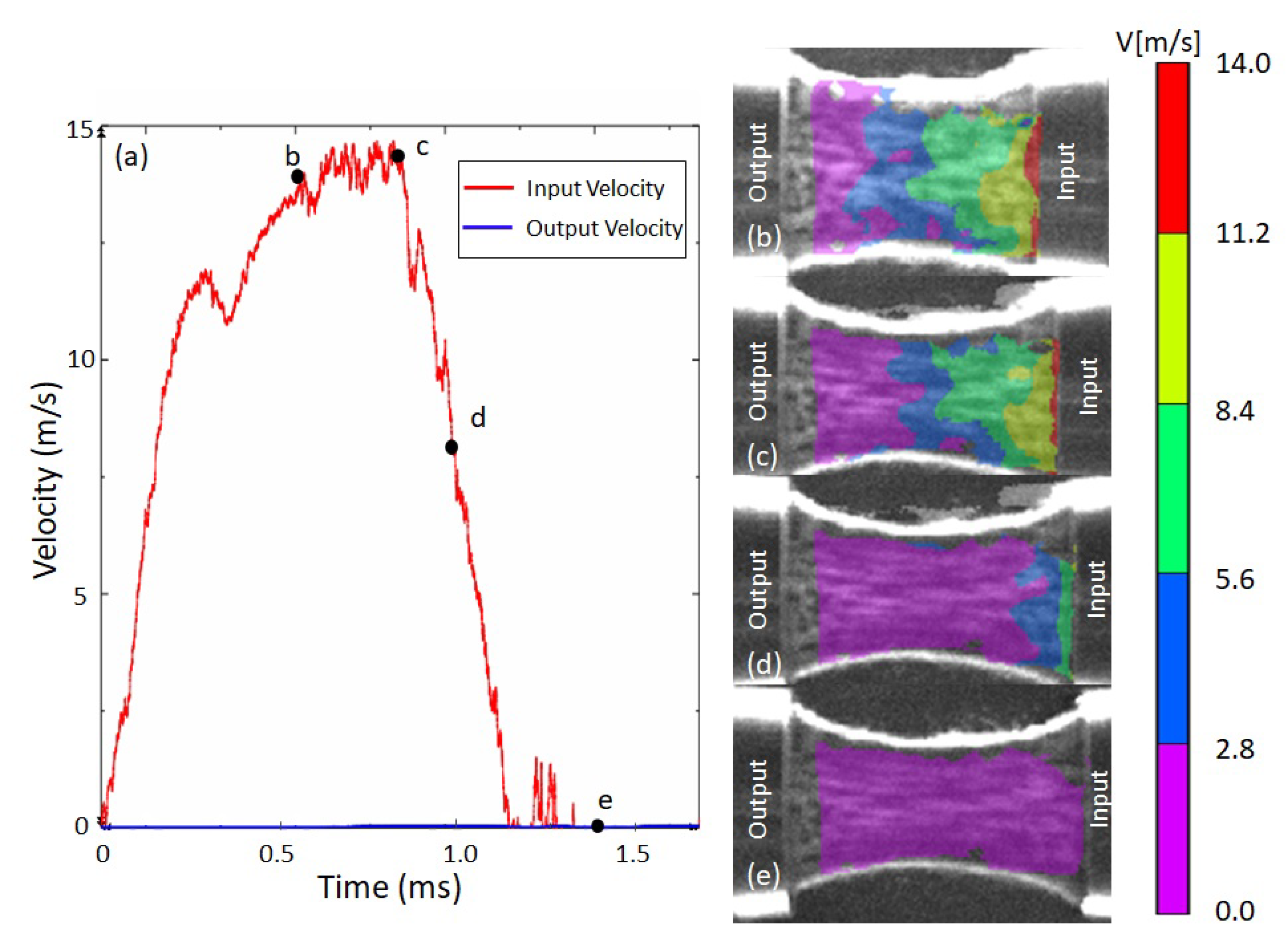
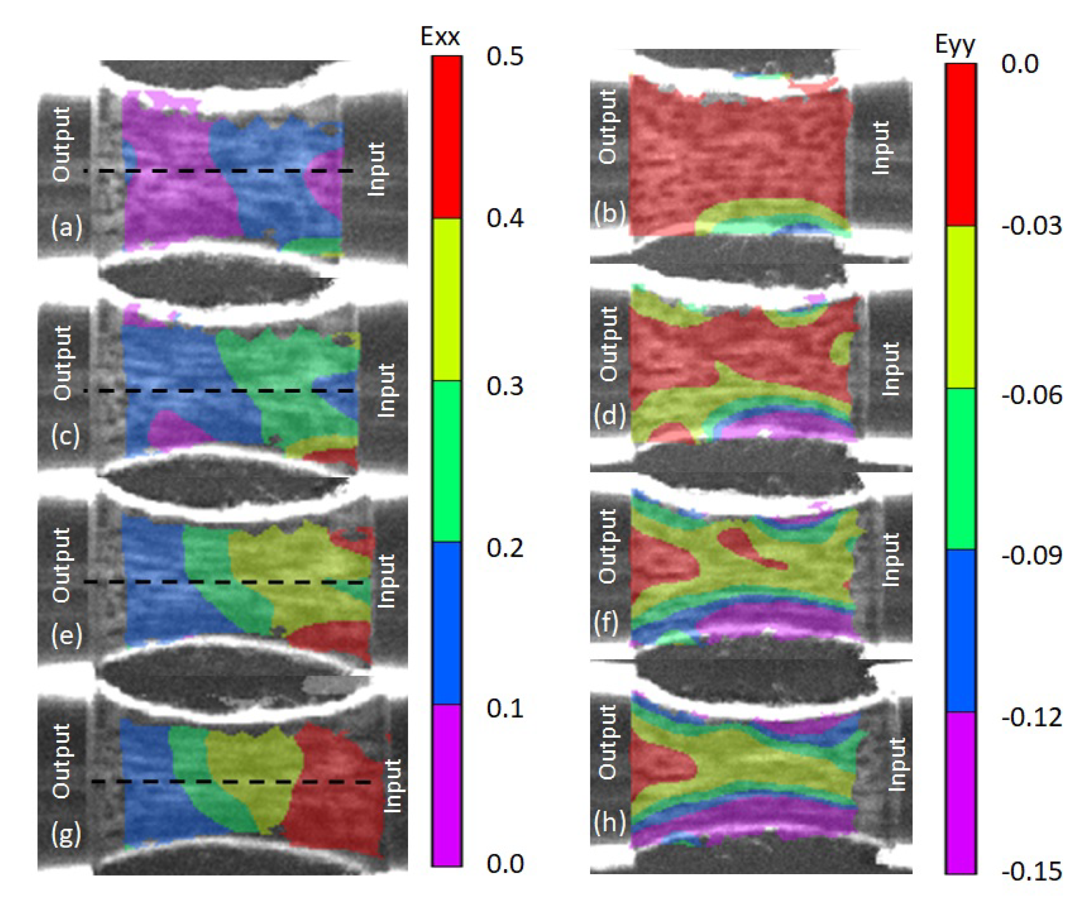
4.4. Dynamic Tensile Testing

The deformation mechanisms were analysed by DIC. The left hand side of Figure 9 shows the evolution of the longitudinal strain at different stages of the experiment and Figure 10a plots the local longitudinal strain distribution at the dashed mid-line. The input bar pulled the nonwoven fabric from the right side. At the initial stage of the loading process ( t = 0.2 ms), the material acquired an oscillating deformation around the 10% as a result of the wave reflection process. The magnitude of the applied strain continued to increase progressively in time ( t = 0.4 ms) up to ≈20% of deformation, maintaining the original distribution. After a certain instant in time ( t = 0.6 ms) the evolution of the strain nearby the output bar froze at a maximum value of 18% deformation leading to a heterogeneous strain field across the specimen (see Figure 9e,g) with an steep increment of deformation located at the input interface once onset of damage was attained at ≈40% of deformation; see Figure 10a. These strain gradients developed even at low strain values before the onset of damage, in contrast to the characteristic homogeneous strain distributions obtained at quasi-static loading regimes. Nevertheless, the strain gradients and damage localisation generated during dynamic testing were in agreement with the response registered during ballistic impact, where larger deformation and final fabric tearing were localised at the impact point, and did not further propagate through the target [19,21].
The lateral strain was analysed, showing evidence of a biaxial stress state across the specimen, see the right hand side of Figure 9. The biaxial stresses were triggered by the large Poisson’s ratio of the material, inducing higher deformations (longitudinal and lateral) at the outer edges of the fabric with respect to the mid-line region. This resulted in an heterogeneous transverse contraction of the material with lower influence of biaxiallity at the mid-line region of the sample, where quasi-constant lateral strains developed. The lateral strain was also directly proportional to the longitudinal strain and the contraction decreased with the distance from the input face.
The strain rate was not constant along the specimen during the dynamic testing. The average strain rate was registered by the strain gauges as ε ˙ 400 s 1 , in agreement with the local DIC measurements; see Figure 10b. These values were four orders of magnitude higher than the previous quasi-static experiments. Overall, the strain rate decreased with the distance from the input interface. The final stage of the experiment ( t = 0.9 ms) presented a different trend in strain rate distribution due to damage localisation, showing a drastic increment near by the input interface.
The deformation was accommodated by the same micromechanisms observed during the quasi-static uniaxial deformation; fibre straightening, rotation and sliding towards the loading direction [15]. Upon stretching, the fibres progressively aligned with the loading direction, increasing the tangent stiffness and the wave speed of the material. The load transference was the result of a complex wave propagation phenomenon between the individual entangled fibres that could not be analysed by conventional one-dimensional wave propagation theory. The stochastic fibre network exhibited an irregular wave front due to the multiple fibre loops, and it evolved with the microstructure, increasing the apparent wave speed when aligning the fibres with the loading direction. For instance, previous authors reported an approximately linear increase in the wave speed of needle-punched nonwoven fabrics from 600 m/s in as-received condition up to 4000 m/s after 25% of deformation [27]. Additionally, the magnitude of the tensile wave decreased with the distance to the input interface due to two different sources of mechanical dissipation: (i) the frictional nature of the deformation micromechanisms and (ii) the partial wave reflection at the entanglement points.
As a result of the variable stiffness and wave speed with the applied deformation, heterogeneous strain gradients developed during the dynamic testing. The wave propagation sequence is analysed in Figure 11. The tensile pulse first propagated into the specimen with velocity c 0 ; see Figure 11a. The stress magnitude progressively decreased with the distance from the input bar due to the internal dissipation of the material. Afterwards, the tensile pulse reached the output interface while faster waves with a higher stress magnitude appeared at the input interface as a result of the increment of stiffness of the material with the deformation ( c 1 > c 0 ); see Figure 11b. Once the two waves (the transmitted and the reflected) travelling at different velocities arrived at the same material point, they created a macromechanical interface with an impedance mismatch at both sides due to the variation of stiffness with the evolution of the fibre alignment, preventing the propagation of larger strain waves into the left side of the specimen; see Figure 11c. The reflections were repeated during the experiment with waves of higher velocity ( c 2 > c 1 ). The result of this iterative process induced a strong strain gradient as shown in Figure 10a, with a dramatic increment of deformation nearby the input bar.
The strain gradients are conventional in Split Hopkinson Bar experiments of soft materials such as gelatin or animal tissue, where the wave propagation velocity is relatively low and the duration of the pulse is not long enough to ensure dynamic force equilibrium between bars [38,41]. The non-homogeneous deformation also occurs in the dynamic testing of non-linear elasto-plastic materials. For instance, it has been observed in metallic or epoxy foams subjected to impact [49,50,51,52]. Foams usually present an initial linear elastic response followed by a plastic plateau of lower stiffness and therefore, two different waves are generated upon impact: a fast elastic precursor and a slower plastic shock front that induces a permanent deformation of the shocked region.
The output forces were analysed to determine the influence of the high strain rates in the mechanical response of the fabric. Figure 12 plots the output stress monitored by the strain gauge vs. the mid-line local longitudinal strains registered by DIC at the input and output interfaces. Although the lack of a constant strain over the specimen hindered the acquisition of a conventional stress-strain constitutive equation, this methodology allows to visualise the variation in strain over the specimen mid-line at each stress level and provides the upper and lower bounds for potential high-rate stress-strain relationships. These curves are compared against the quasi-static stress-strain constitutive relationship. The mechanical response can be divided in two different stages; an initial sudden increase in the stiffness within the range 10–15% of deformation, and a progressive increment of the load due to the development of the strain gradient and fibre sliding on the input interface. This analysis showed evidence of the strain rate dependency of the frictional mechanisms between entangled fibres in agreement with previous parametrical studies carried out by means of numerical simulations [21]. An increment of the fibre pull-out strength was formerly defined to fit the ballistic limit of the as-received fabric subjected to ballistic impact of small metallic fragments, leading to a virtual increment of the ply stiffness and strength when subjected to in-plane dynamic tensile loads, suggesting a strain rate dependency of the nature observed during the present SHTB experimental campaign.

5. Conclusions

This study presents the first attempt to characterise the dynamic response of dyneema needle-punched nonwoven fabrics specifically designed for ballistic protection. Nonwoven fabrics present a large energy absorption capacity due to their ability to sustain load at very large strains and the frictional micromechanisms triggered during in-plane deformation, and have the capacity to improve the ballistic performance of conventional dry woven barriers acting as cushion layers. The experimental dynamic characterisation of the in-plane response of a needle-punched nonwoven fabric was conducted on a novel Split-Hopkinson Tensile Bar device specifically developed for this study. The apparatus included a high-sensitivity output bar to register the response of the soft fabrics and had a pulse duration of 1 ms to impose large deformations. The gauge length of the specimen was also long enough (35 mm) to ensure at least one representative volume element was tested. This experimental campaign offered detailed understanding on the wave propagation phenomenon in nonwoven fabrics by a combination of high-speed photography and Digital Image Correlation (DIC). The device was able to provide quantitative measurements of the wave speed, the evolution of strain fields and the wave interaction. It also presented several limitations summarised as; (i) low time resolution of the high-speed camera and (ii) a lack of force equilibrium in the bars. These limitations have been considered during the data analysis.
The deformation for dynamic loading was accommodated by the same micromechanisms observed during quasi-static in-plane tensile testing and ballistic impact, which comprised fibre straightening, rotation and sliding with the loading direction. The initial wave propagation velocity of the as-received nonwoven fabric was characterised as c = 827.5 m/s, exceptionally slow compared to those of bulk polyethylene or ultrahigh molecular weight polyethylene fibres. The main differences between quasi-static and dynamic loading regimes was given by the heterogeneous strain gradient developed at high-strain rates, in contrast with the homogeneous deformation field observed before onset of damage in quasi-static experiments. As a result of the heterogeneous strain field, the strain rate distribution was also non constant along the specimen, with an average value of ε ˙ 400 s 1 , four orders of magnitude higher than previous quasi-static tests.
The heterogeneous strain field was a consequence of the non-linear pseudo-plastic response of the fabric and the internal energy dissipation mechanisms related to the frictional deformation processes such as fibre sliding. The load transference process was dictated by the wave propagation phenomenon between individual entangled fibres, and it depended on the current fibre orientation distribution function. Upon stretching, the fibres progressively aligned with the loading direction, increasing the tangent stiffness of the material, and therefore, the wave propagation velocity. As a result, during dynamic testing, the differences in fibre orientation distribution function and stiffness arising from the interference of reflected waves generated internal impedance mismatch fronts, preventing the propagation of larger strain waves towards the output interface. In consequence, after a certain period of time, the deformation nearby the output interface froze; meanwhile, large strain gradients and fibre pull-out developed nearby the input interface. Similar gradients have been previously reported for ballistic tests, showing large deformations and localised damage at the impact point.
The output forces were analysed to determine the influence of high strain rates in the mechanical response of the nonwoven fabric. Although the strain gradients hindered the development of a theoretical equilibrium stress-state in the bars, the proposed analysis established reasonable bounds for potential dynamic stress-strain curves. The strain rate sensitivity was found in the frictional mechanisms between the entangled fibres, such as fibre sliding, in agreement with the previous parametrical studies. In particular, an increment of the stiffness for low applied strains was exhibited during dynamic loading. This study provides the basis to develop algorithms to predict the wave propagation phenomenon of needle-punched nonwoven fabrics and closes the gap in knowledge regarding their mechanical response when subjected to dynamic loads such as ballistic impact.

Author Contributions

Conceptualization, F.M.-H., A.P. and N.P.; Data curation, F.M.-H.; Formal analysis, F.M.-H. and A.P.; Funding acquisition, N.P., C.G. and J.L.; Investigation, F.M.-H. and A.P.; Methodology, A.P.; Resources, N.P.; Supervision, Á.R., N.P., C.G. and J.L.; Validation, F.M.-H. and A.P.; Visualization, F.M.-H.; Writing—original draft, F.M.-H.; Writing—review & editing, A.P., Á.R., N.P., C.G. and J.L. All authors have read and agreed to the published version of the manuscript.

Funding

This research was supported by The Royal Society through the grant [RGS/R2/180091].

Acknowledgments

The collaboration of S. Carter to manufacture the Split-Hopkinson bar components is gratefully acknowledged.

Conflicts of Interest

The authors declare no conflict of interest.

References

  1. Cheeseman, B.A.; Bogetti, T.A. Ballistic impact into fabric and compliant composite laminates. Compos. Struct. 2003, 61, 161–173. [Google Scholar] [CrossRef]
  2. Mawkhlieng, U.; Majumdar, A.; Laha, A. A review of fibrous materials for soft body armour applications. RSC Adv. 2020, 10, 1066–1086. [Google Scholar] [CrossRef]
  3. Tabiei, A.; Nilakantan, G. Ballistic impact of dry woven fabric composites: A review. Appl. Mech. Rev. 2008, 61, 010801. [Google Scholar] [CrossRef]
  4. Martínez-Hergueta, F.; Ridruejo, A.; González, C.; LLorca, J. Ballistic performance of hybrid nonwoven/woven polyethylene fabric shields. Int. J. Impact Eng. 2018, 111, 55–65. [Google Scholar] [CrossRef]
  5. Laible, R.; Henry, M. A Review of the Development of Ballistic Needle-Punched Felts; Technical Report, No. C/PSEL-TS-167; Clothing and Personal Life Support Equipment Laboratory. U.S. Army Natick Laboratories: Natick, MA, USA, 1969. [Google Scholar]
  6. Chocron, S.; Pintor, A.; Cendón, D.; Gálvez, F.; Sánchez-Gálvez, V. Simulation of ballistic impact in a polyethylene non-woven felt. In Proceedings of the 20th Internationa Symposium on Ballistics, Orlando, FL, USA, 23–27 September 2002; pp. 23–27. [Google Scholar]
  7. Thomas, H.L.; Bhatnagar, A.; Wagner, L.L. Needle-Punched Non-Woven for High Fragment Protection. In Proceedings of the 14th International Conference of Composite Materials, San Diego, CA, USA, 14–18 July 2003. [Google Scholar]
  8. Ipson, T.W.; Wittrock, E.P. Response of Non-Woven Synthetic Fiber Textiles to Ballistic Impact; Technical Report, No. TR-67-8-CM; Denver Research Institute: Denver, CO, USA, 1966. [Google Scholar]
  9. Lee, S.H.; Kang, T.J. Mechanical and Impact Properties of Needle Punched Nonwoven Composites. J. Compos. Mater. 2000, 34, 816–840. [Google Scholar] [CrossRef]
  10. Russell, S.; Pourmohammadi, A.; Ezra, I.; Jacobs, M. Formation and properties of fluid jet entangled HMPE impact resistant fabrics. Compos. Sci. Technol. 2005, 65, 899–907. [Google Scholar] [CrossRef]
  11. Lin, J.H.; Hsu, C.H.; Meng, H.H. Process of preparing a nonwoven/filament/woven-fabric sandwich structure with cushioning effect of ballistic resistance. Fibres Text. East. Eur. 2005, 13, 43–47. [Google Scholar]
  12. Reddy, P.R.S.; Reddy, T.S.; Srikanth, I.; Kushwaha, J.; Madhu, V. Development of cost effective personnel armour through structural hybridization. Def. Technol. 2019. [Google Scholar] [CrossRef]
  13. Vila-Ortega, J.; Ridruejo, A.; Martínez-Hergueta, F. Multiscale numerical optimisation of hybrid metal/nonwoven shields for ballistic protection. Int. J. Impact Eng. 2020, 138, 103478. [Google Scholar] [CrossRef]
  14. Chocron, S.; Pintor, A.; Gálvez, F.; Roselló, C.; Cendón, D.; Sánchez-Gálvez, V. Lightweight polyethylene non-woven felts for ballistic impact applications: Material characterization. Compos. Part B Eng. 2008, 39, 1240–1246. [Google Scholar] [CrossRef]
  15. Martínez-Hergueta, F.; Ridruejo, A.; González, C.; LLorca, J. Deformation and energy dissipation mechanisms of needle-punched nonwoven fabrics: A multiscale experimental analysis. Int. J. Solids Struct. 2015, 64, 120–131. [Google Scholar] [CrossRef]
  16. Abtew, M.A.; Boussu, F.; Bruniaux, P.; Loghin, C.; Cristian, I. Ballistic impact mechanisms-A review on textiles and fibre-reinforced composites impact responses. Compos. Struct. 2019, 223, 110966. [Google Scholar] [CrossRef]
  17. Yan, R.; Zhang, Q.; Shi, B.; Qin, Z.; Wei, S.; Jia, L. Investigating the integral-structure of HRBP/CHP/CF consisting of non-woven flexible inter/intra-ply hybrid composites: Compression, puncture-resistance, electromagnetic interference shielding effectiveness. Compos. Struct. 2020, 248, 112501. [Google Scholar] [CrossRef]
  18. Thomas, G. Non-woven fabrics for military applications. In Military Textiles; Elsevier: Sawston, Cambridge, UK, 2008; pp. 17–48. [Google Scholar]
  19. Martínez-Hergueta, F.; Ridruejo, A.; Gálvez, F.; González, C.; LLorca, J. Influence of fiber orientation on the ballistic performance of needle-punched nonwoven fabrics. Mech. Mater. 2016, 94, 106–116. [Google Scholar] [CrossRef] [Green Version]
  20. Russell, B.; Karthikeyan, K.; Deshpande, V.; Fleck, N. The high strain rate response of ultra high molecular-weight polyethylene: From fibre to laminate. Int. J. Impact Eng. 2013, 60, 1–9. [Google Scholar] [CrossRef]
  21. Martínez-Hergueta, F.; Ridruejo, A.; González, C.; Llorca, J. Numerical simulation of the ballistic response of needle-punched nonwoven fabrics. Int. J. Solids Struct. 2017, 106, 56–67. [Google Scholar] [CrossRef]
  22. Gama, B.; Lopatnikov, S.; Gillespie, J., Jr. Hopkinson bar experimental technique: A critical review. Appl. Mech. Rev. 2004, 57, 223–250. [Google Scholar] [CrossRef]
  23. Song, B.; Chen, W. Dynamic stress equilibration in split Hopkinson pressure bar tests on soft materials. Exp. Mech. 2004, 44, 300–312. [Google Scholar] [CrossRef]
  24. Yang, L.; Shim, V. An analysis of stress uniformity in split Hopkinson bar test specimens. Int. J. Impact Eng. 2005, 31, 129–150. [Google Scholar] [CrossRef]
  25. Gitman, I.; Askes, H.; Sluys, L. Representative volume: Existence and size determination. Eng. Fract. Mech. 2007, 74, 2518–2534. [Google Scholar] [CrossRef]
  26. Zhu, D.; Mobasher, B.; Rajan, S. Dynamic tensile testing of Kevlar 49 fabrics. J. Mater. Civ. Eng. 2011, 23, 230–239. [Google Scholar] [CrossRef]
  27. Chocron, S.; Pintor, A.; Cendón, D.; Roselló, C.; Sanchez-Galvez, V. Characterization of Fraglight Non-Woven Felt and Simulation of FSP’s Impact in It; Technical Report; Technical University of Madrid: Madrid, Spain, 2002. [Google Scholar]
  28. Chen, W.; Zhang, B.; Forrestal, M. A split Hopkinson bar technique for low-impedance materials. Exp. Mech. 1999, 39, 81–85. [Google Scholar] [CrossRef]
  29. Luo, H.; Dai, C.; Gan, R.; Lu, H. Measurement of Youngs modulus of human tympanic membrane at high strain rates. J. Biomech. Eng. 2009, 131, 064501. [Google Scholar] [CrossRef]
  30. Pervin, F.; Chen, W. Dynamic mechanical response of bovine gray matter and white matter brain tissues under compression. J. Biomech. 2009, 42, 731–735. [Google Scholar] [CrossRef] [PubMed]
  31. Shergold, O.; Fleck, N.; Radford, D. The uniaxial stress versus strain response of pig skin and silicone rubber at low and high strain rates. Int. J. Impact Eng. 2006, 32, 1384–1402. [Google Scholar] [CrossRef]
  32. Pellegrino, A.; Tagarielli, V.; Gerlach, R.; Petrinic, N. The mechanical response of a syntactic polyurethane foam at low and high rates of strain. Int. J. Impact Eng. 2015, 75, 214–221. [Google Scholar] [CrossRef] [Green Version]
  33. Wang, L.; Labibes, K.; Azari, Z.; Pluvinage, G. Generalization of split Hopkinson bar technique to use viscoelastic bars. Int. J. Impact Eng. 1994, 15, 669–686. [Google Scholar] [CrossRef]
  34. Shim, J.; Mohr, D. Using split Hopkinson pressure bars to perform large strain compression tests on polyurea at low, intermediate and high strain rates. Int. J. Impact Eng. 2009, 36, 1116–1127. [Google Scholar] [CrossRef]
  35. Rao, S.; Shim, V.; Quah, S. Dynamic mechanical properties of polyurethane elastomers using a nonmetallic Hopkinson bar. J. Appl. Polym. Sci. 1997, 66, 619–631. [Google Scholar] [CrossRef]
  36. Chen, W.; Lu, F.; Zhou, B. A quartz-crystal-embedded split Hopkinson pressure bar for soft materials. Exp. Mech. 2000, 40, 1–6. [Google Scholar] [CrossRef]
  37. Trexler, M.; Lennon, A.; Wickwire, A.; Harrigan, T.; Luong, Q.; Graham, J.; Maisano, A.; Roberts, J.; Merkle, A. Verification and implementation of a modified split Hopkinson pressure bar technique for characterizing biological tissue and soft biosimulant materials under dynamic shear loading. J. Mech. Behav. Biomed. Mater. 2011, 4, 1920–1928. [Google Scholar] [CrossRef] [PubMed]
  38. Zeng, H.; Bailly, P. Experimental characterization of dynamic behaviour of gelatin-based material using DIC. Polym. Test. 2017, 63, 298–306. [Google Scholar] [CrossRef]
  39. Gerlach, R.; Kettenbeil, C.; Petrinic, N. A new split Hopkinson tensile bar design. Int. J. Impact Eng. 2012, 50, 63–67. [Google Scholar] [CrossRef]
  40. Nie, H.; Suo, T.; Wu, B.; Li, Y.; Zhao, H. A versatile split Hopkinson pressure bar using electromagnetic loading. Int. J. Impact Eng. 2018, 116, 94–104. [Google Scholar] [CrossRef]
  41. Khatam, H.; Liu, Q.; Ravi-Chandar, K. Dynamic tensile characterization of pig skin. Acta Mech. Sin. 2014, 30, 125–132. [Google Scholar] [CrossRef]
  42. Koerber, H.; Xavier, J.; Camanho, P. High strain rate characterisation of unidirectional carbon-epoxy IM7-8552 in transverse compression and in-plane shear using digital image correlation. Mech. Mater. 2010, 42, 1004–1019. [Google Scholar] [CrossRef]
  43. Russell, S. Handbook of Nonwovens, The Textile Institute; Elsevier: Sawston, Cambridge, UK, 2007. [Google Scholar]
  44. Martínez-Hergueta, F.; Ridruejo, A.; González, C.; LLorca, J. A multiscale micromechanical model of needle-punched nonwoven fabrics. Int. J. Solids Struct. 2016, 96, 81–91. [Google Scholar] [CrossRef]
  45. Chen, W.; Song, B. Split Hopkinson (Kolsky) Bar: Design, Testing and Applications; Springer Science & Business Media: Dordrecht, The Netherlands, 2010. [Google Scholar]
  46. Koh, A.; Shim, V.; Tan, V. Dynamic behaviour of UHMWPE yarns and addressing impedance mismatch effects of specimen clamps. Int. J. Impact Eng. 2010, 37, 324–332. [Google Scholar] [CrossRef]
  47. Schuyer, J. Sound velocity in polyethylene. J. Polym. Sci. 1959, 36, 475–483. [Google Scholar] [CrossRef]
  48. Chocron, S.; King, N.; Bigger, R.; Walker, J.; Heisserer, U.; Van der Werff, H. Impacts and waves in Dyneema® HB80 strips and laminates. J. Appl. Mech. 2013, 80, 031806. [Google Scholar] [CrossRef]
  49. Lopatnikov, S.; Gama, B.; Haque, J.; Krauthauser, C.; Gillespie, J.; Guden, M.; Hall, I. Dynamics of metal foam deformation during Taylor cylinder-Hopkinson bar impact experiment. Compos. Struct. 2003, 61, 61–71. [Google Scholar] [CrossRef] [Green Version]
  50. Elnasri, I.; Pattofatto, S.; Zhao, H.; Tsitsiris, H.; Hild, F.; Girard, Y. Shock enhancement of cellular structures under impact loading: Part I Experiments. J. Mech. Phys. Solids 2007, 55, 2652–2671. [Google Scholar] [CrossRef] [Green Version]
  51. Deshpande, V.; Fleck, N. High strain rate compressive behaviour of aluminium alloy foams. Int. J. Impact Eng. 2000, 24, 277–298. [Google Scholar] [CrossRef] [Green Version]
  52. Song, B.; Forrestal, M.; Chen, W. Dynamic and Quasi-Static Propagation of Compaction Waves in a Low-Density Epoxy Foam. Exp. Mech. 2006, 46, 115–120. [Google Scholar] [CrossRef]
Figure 1. Split-Hopkinson tensile bar experimental set up. (a) Schematic of the different components of the SHTB, (b) gripped specimen between bar ends and (c) aluminium and brass components of the grips.
Applsci 10 05081 g001
Figure 2. Evolution of fibre orientation distribution function with the applied strain. (a) As-receive nonwoven fabric and (b) after 40% of deformation along the transverse direction (TD) [15].
Applsci 10 05081 g002
Figure 3. (a) Representative nominal stress vs. engineering strain curves for quasi-static strain rates. (b) Comparison between monotonic and cyclic deformation [15].
Applsci 10 05081 g003
Figure 4. Contour plots of the logarithmic strain in the loading direction at different applied strains (a) 50%, (b) 70% and (c) 85% [15,44].
Applsci 10 05081 g004
Figure 5. Deformation of a 350 × 350 mm 2 target impacted by a small steel sphere of 5.5 mm diameter. Ballistic response for initial impact velocity 300 m/s at t = 500 μ s, below the ballistic limit. (a) Contour plot of the maximum principal logarithmic strain, showing the fronts of the longitudinal and transverse waves (dashed line) and (b) experimental deflection. (c) Fibre disentanglement for impact velocity 360 m/s at t = 175 μ s, above the ballistic limit [19,21].
Applsci 10 05081 g005
Figure 6. Representative nominal stress vs. engineering strain curves for different gauge lengths.
Applsci 10 05081 g006
Figure 7. (a) Voltage vs. time for each strain gauge. The gauges 1 and 2 were installed in the input bar and the gauge 3 was installed in the output bar. (b) Forces vs. time monitored at input and output bar ends.
Applsci 10 05081 g007
Figure 8. Validation of DIC measurements. (a) Velocities at the input and output interfaces registered by the strain gauges. Corresponding contour plots of longitudinal velocities at (b) t = 0.6 ms, (c) t = 0.8 ms, (d) t = 1.0 ms and (e) t = 1.4 ms.
Applsci 10 05081 g008
Figure 9. Evolution of the longitudinal strain ε x (a,c,e,g) and lateral strain ε y (b,d,f,h). (a,b) t = 0.2 ms, (c,d) t = 0.4 ms, (e,f) t = 0.6 ms, (g,h) t = 0.9 ms. Dashed line represents the mid-line used to monitor longitudinal strains and strain rates in Figure 10.
Applsci 10 05081 g009
Figure 10. Evolution of spacial distribution of local longitudinal (a) strain and (b) strain rate. X = 0 mm stand for the material particles at the output interface, meanwhile X 34 mm stand for the material particles at the input interface.
Applsci 10 05081 g010
Figure 11. Wave rebound in the specimen during dynamic testing. c 0 < c 1 < c 2 . (a) Initial wave propagation at velocity c 0 . (b) Reflection of the first wave arriving at the output bar. (c) Interference of both waves at an intermediate point of the specimen, while new waves with velocity c 2 are created at the input bar interface.
Applsci 10 05081 g011
Figure 12. Output stress vs. local engineering strain at different locations of the specimen. Blue dashed line stands for the local strain at the output interface (dynamic lower bound, X = 0 mm in Figure 10) and red dashed line stands for the local strain at the input interface (dynamic upper bound, X = 34 mm in Figure 10).
Applsci 10 05081 g012

