Article

Influence of Ice Accumulation on the Structural Dynamic Behaviour of Composite Rotors

1
Institute of Lightweight Engineering and Polymer Technology, Technische Universität Dresden, 01067 Dresden, Germany
2
Weidmüller Monitoring Systems GmbH, 01067 Dresden, Germany
*
Author to whom correspondence should be addressed.
Appl. Sci. 2020, 10(15), 5063; https://doi.org/10.3390/app10155063
Submission received: 26 June 2020 / Revised: 15 July 2020 / Accepted: 21 July 2020 / Published: 23 July 2020
(This article belongs to the Section Mechanical Engineering)

Abstract

:

Featured Application

The current investigations on the ice accumulation at composite rotors can be applied in the wind industry energy sector for the structural integrity identification of wind turbines. Specifically, by means of online rotor blade monitoring and the resulting ice detection, a potential online system can increase availability of the turbines during the winter months using the envisaged ice detection algorithms.

Abstract

The implementation of wind turbines as a source of sustainable, renewable energy is increasing. Although the prospects of renewable energy development are promising, ice accumulation on turbine blades still stands as a major operational issue. Excessive ice mass on turbine blades can lead to damage or total failure of the blades but also to the nacelle gearbox and to the generator. Therefore, a detailed understanding of the ice accumulation on the composite blades and the effect on their modal properties can be beneficial and give an insight before catastrophic failure occurs. On the one hand, it can be understood how ice accumulation affects the profile of the composite surface to consequently identify the relationships between ice accumulation and mass, stiffness, as well as damping distribution. On the other hand, by mapping these relationships, the first step is performed towards solving the inverse problem, which is to identify critical ice accumulation at an early stage based on modal properties. In this way, ice detection and identification can provide significant savings in time and costs. To investigate the basic relationships between ice accumulation and structural dynamic behaviour, an experimental rotor test rig is developed, combining an electromotor with a climate chamber. The test rig simulates various environmental conditions under different rotational speeds and ice distributions. The first experimental tests are performed on a glass-fibre reinforced epoxy rotor, and several measurements are conducted deploying different kinds of icing and temperature conditions. Various sensors are applied to characterise the vibration response as well as mass, type, and spatial distribution of the ice. The results are evaluated with regard to identifying unknown relations between ice accumulation and the structural dynamic behaviour of composite rotors.

1. Introduction

The increased use of wind turbines as a source of renewable energy is an international trend, as most European countries saw a significant increase in new installed wind energy production capacity from the previous year [1,2]. Of the new installations due before 2020, the overwhelming majority will be installed in remote, cold areas. Although the prospects of renewable energy development are promising in this area, ice accumulation on turbine blades still stands as a major operational issue.
Excessive ice mass on the turbine blades, as shown in Figure 1, can lead to damage or complete destruction of the nacelle gearbox or the generator. Typical ice profiles at rotor blades consist of so-called rim-ice [3,4]. Ice can also be non-uniformly distributed on the blades, which leads to asymmetric rotation due to imbalance and can have detrimental consequences, such as the reduced lifetime of gears and bearings. Ice accumulation also changes the profile of the blade airfoil and yields energy losses. There is also the danger of a wind turbine throwing ice from the spinning blades, referred to as “ice throw”, which can be fatal even with a mere 200 g of ice or 40 J of energy, respectively [5].
The goal of this paper is the identification of changes in the modal properties of a glass fibre-reinforced plastic (GFRP) rotor and a better understanding of how ice accumulation affects the profile of the composite surface, and consequently to describe the relationships between ice accumulation, ice mass, and stiffness distribution. In this way, a more precise control of rotor operations due to different icing conditions and other climate events can be enabled. A novel rotor test rig is developed that simulates various environmental conditions under different rotational speeds and ice distributions. A laser scanning profiler is used to determine the various icing conditions, such as thickness and distribution of accumulating ice. The findings can be used to identify distinct features in sensor data without the need to properly determine the ice accumulation. This also enables the proper determination and, furthermore, simulation of icing events that can be used in monitoring systems [6,7].
The influence of damage initiation and propagation at GFRP rotors has already been extensively investigated and a non-monotonic shift of the eigenfrequencies has been observed, due to non-linear mechanical properties of the rotors and the damage type and extent [8]. However, experimental investigations for ice accumulation on composite rotors considering the modal properties are relative few [9,10]. Specifically, typical icing conditions on GFRP rotor blades are reported on the scope of ice detection and identification at wind turbines [11].
Other applications in the field of wind turbine monitoring are based on the physical principle, that ice accumulation changes the vibration behaviour response of a structure [12,13]. Specifically, most applications use the mass changes due to icing, which causes changes in the natural frequencies. Such methods can achieve a measurement resolution for the thickness of the ice in the millimetre range. The advantage lies in the fact that they can be used during operation as well as in static conditions, which allows for measurements to be taken before starting the turbine, thus ensuring proper operation [9]. Currently available industrial systems use accelerometers as well to detect changes in modal properties and, thus, prevent damage to gearboxes, engine bearings etc. due to dynamic loads. The principle is based on the fact that different vibrations are characteristic for certain causes [14,15]. However, the actual icing condition is usually estimated, for example, by a small number of capacitive sensors integrated in the blades or ultrasonic sensors mounted at a large distance on the nacelle providing local thickness changes [16].
Laser distance sensors or videometric techniques are already used in a variety of systems, for non-contact blade displacement monitoring [17,18,19]. However, their purpose is to prevent a total failure by measuring the displacements of the rotor blades along the rotor axis. The challenge is to detect the approach of a blade at an early stage and, thus, the hitting against the tower, which can be caused by the tilting of the nacelle or by mass changes of the rotor blades.

2. Experimental Investigation of Ice Accumulation (Materials and Methods)

The structural properties of a GFRP rotor are experimentally investigated with the goal to identify and describe the dependency of the modal properties from the temperature and ice distribution by the means of operational vibration analysis. For the experimental investigation, a circular GFRP disc rotor was chosen to determine the fundamental changes in the modal parameters caused by ice accumulation. The relatively simple structure was chosen to avoid more complex phenomena due to the airfoil geometry of a rotor blade.

2.1. Selection of Investigated Composite Rotor

The investigated rotor consists of preforms, which are fabricated using the Tailored Fibre Placement (TFP) process. The fibre architecture consists of symmetrically arranged radial (Ra) and tangential (Ta) preforms resulting in a polar orthotropic behaviour, with planar and polar stress distribution along the radius r and the circumference ϕ, respectively, featuring a symmetric composite lay-up of (Ra/Ta/Ra)s as presented in Figure 2. The resin injection moulding process was deployed to consolidate the preforms, with a rotor thickness of 5 mm and outer radius of 250 mm.
The sensors and actuators required for vibration analysis are attached to the back of the rotor using res-in. The exact position of each actuator and sensor is identified by determining the maximum deflection of the superimposed first 12 mode shapes. Therefore, an initial response analysis is performed employing a laser scanning vibrometer measuring the vibration response of 128 evenly spread points. Since, the amount of actuators and sensors are limited to the amount of channels provided by the slip ring, the described measurement procedure is fairly limited, hence closely spaced mode shapes were considered, but cannot be identified properly.

2.2. Experimental Setup and Design

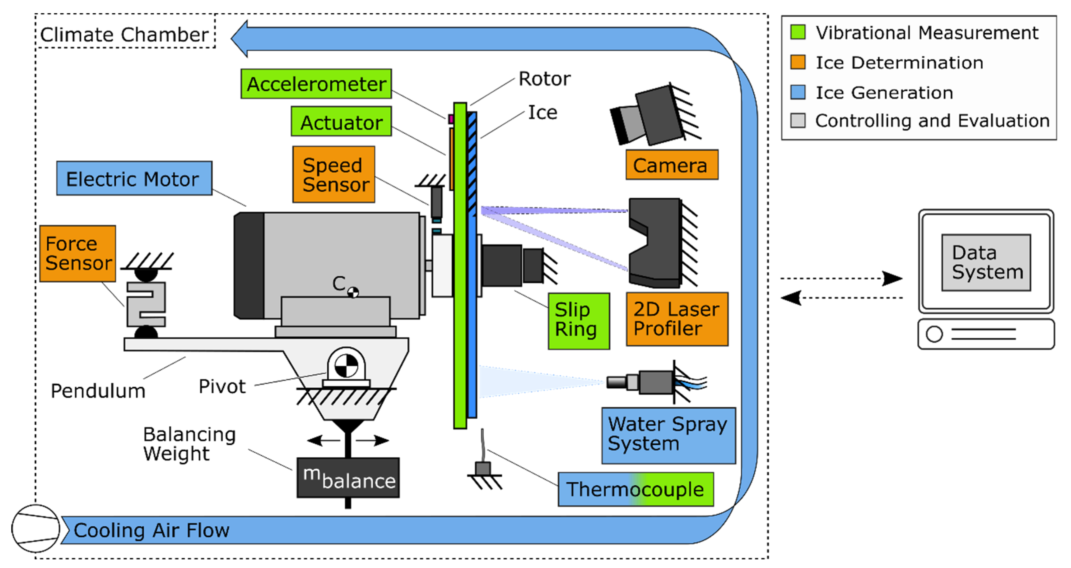
The experimental setup consists of a rotor test rig positioned inside a climate chamber. Figure 3 contains a schematic view of the test stand assembly. It is equipped with four different measurement systems in order to provide the ice mass, the ice distribution and thickness, as well as the structural dynamic behaviour of the rotor.
The climate chamber (KBV 2000-C, Feutron) varies the temperature between 25 °C down to 20 °C, and it is equipped with a video camera (HERO7 Black, GoPro), which monitors the tests and allows for live viewing. A containment surrounds the rotor inside the chamber in order to prevent the water or detached ice from damaging any surrounding electrical components. As mentioned above, the experimental setup consists of four subsystems, an ice-generating subsystem, a vibrational measurement sub-system, an ice-detecting system, and an acquisition and processing system, as shown in Figure 3 and described in more detail below.
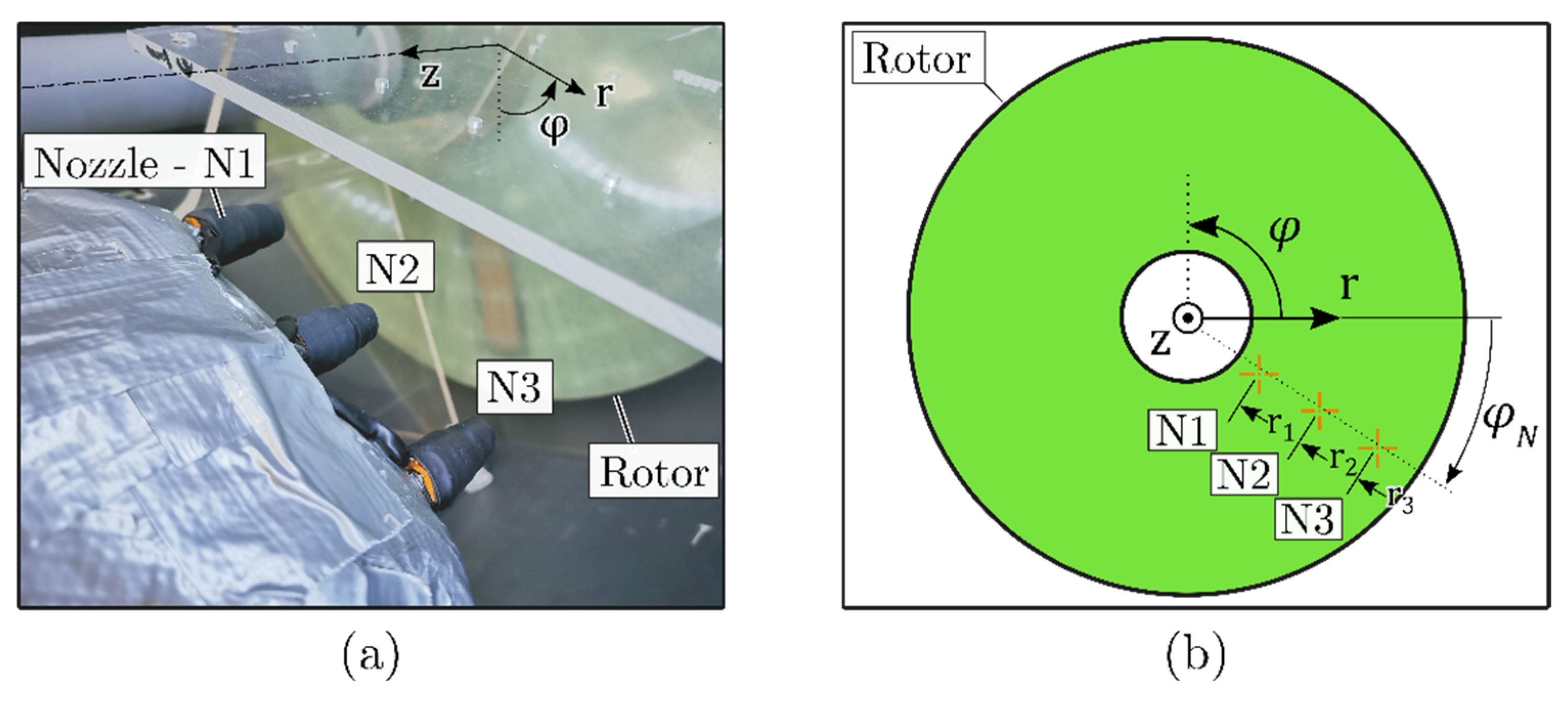
An ice-generating subsystem containing a water spray unit is positioned in front of a rotor that is attached to the motor. The three nozzles shown in Figure 3 spray cold water in the direction of the rotor while an electric motor (M21R 100L, VEB) rotates at different speeds to achieve an adjustable ice accumulation. Nozzle no. 1 (N1) is positioned at the root of the rotor (r1 ≈ 125 mm), nozzle no. 2 (N2) at the middle of the rotor (r2 ≈ 175 mm), and nozzle no. 3 (N3) at the outer side of the rotor (r3 ≈ 225 mm), forming a (N1, N2, N3) setup. The nozzles are mounted onto an aluminium bar, which is attached to the containment of the test bench, pointing towards the centre of the rotor at an angle of approximately φN ≈ −35°. Each nozzle can be activated/opened (1) or deactivated/closed (0) separately.
The structural dynamic behaviour of the rotor is determined by the vibration measurement subsystem consisting of three accelerometers, placed on the back of the rotor, providing the dynamic response in the time domain. Two macro fibre composite piezo actuators (MFC) enable a frequency band-limited excitation with a frequency range of up to 1000 Hz. The MFCs are placed radially and perform an expansion along the same direction resulting in bending forces on the rotor. Various excitations have been tested; due to the relatively high stiffness of the rotor, eventually only chirp signals were found to produce proper excitation. More specifically, a chirp signal with a duration of 40 s is sent to the actuators.
In order to measure the ice thickness distribution and/or mass, an ice-detecting subsystem is equipped with a triangulation laser profiler (LJ-V7300, KEYENCE) that constantly scans the profile along a radial line on the rotor’s surface. The rotor is mounted to the motor, which is placed on a pendulum, thus being free to rotate on an axle via pivots (point C in Figure 4). Ice accumulation will cause a small rotation of the lever, which will be measured by a force sensor on the back. Additional mass is added to the centre of gravity to increase inertia, reducing oscillations caused by the spinning rotor.
The vibration analysis is performed in several basic steps and using the vibration excitation and acquisition described above via MFCs or accelerometers. First, the chamber is cooled down to the desired temperature and kept constant till the end of one measurement series. Subsequently, the initial vibration response of the rotor is determined under static conditions. The rotor is then rotated at a certain speed and a further analysis is carried out to eliminate harmonics and other rotation-induced side effects. Then the nozzles are opened, and vibration measurements are carried out at regular intervals during rotation enabling the detection of ice-dependent changes.
A series of measurements are conducted to monitor the relations between different experimental parameters, see Table 1. For each parameter setup, an experimental modal analysis is performed. The first measurements (M01–M09) were performed under different temperatures from +20 °C to −20 °C with a 5 °C decrement. At M10–M15 all three nozzles are opened at 100 RPM in order to achieve a full surface ice accumulation at the rotor, thus affecting all modal parameters. At M16-M20 only the outer nozzle is active creating ice at the outer one-third part. Similarly, for the measurements M21–M25 and M26–M30, the other two nozzles are separately activated, thus causing ice accumulation on a limited area along the circumference. In total, 30 measurements are conducted, presented, and discussed.

3. Results and Discussion

In this section, the results of the previously introduced measurements are presented and discussed, mainly concerning changes of modal properties of a GFRP rotor under cold and icing conditions. The icing was found to be similar to icing occurring on wind turbine blades [3]. It should be noted that in the following graphs each line represents the response spectra of all three accelerometers averaged in the frequency domain. For the temperature-dependent vibration analyses, three measurements are conducted at each interval and the signals are averaged in the frequency domain. For ice-dependent measurements, due to the proceeding ice accumulation only a single measurement is performed at each interval. Due to the environmental conditions in the climate chamber, it was not possible to stop the nozzle operation during ice accumulation. An interruption of the icing process would have caused water to freeze within the nozzles rendering them unusable. Therefore, the icing process was slowed down to such an extent that the increase in layer thickness during the modal analysis was approximately 0.1 mm. Since the uppermost ice layer does not form a continuous ice layer, but isolated ice speckles, there is no measurable increase in stiffness, which would lead to changing modal properties. Due to the layer thickness of 0.1 mm and the resolution of the force sensor, an increase in mass cannot be measured as well. The icing process was repeated three times using the same nozzle setup.

3.1. Temperature-Dependent Shift of Modal Properties

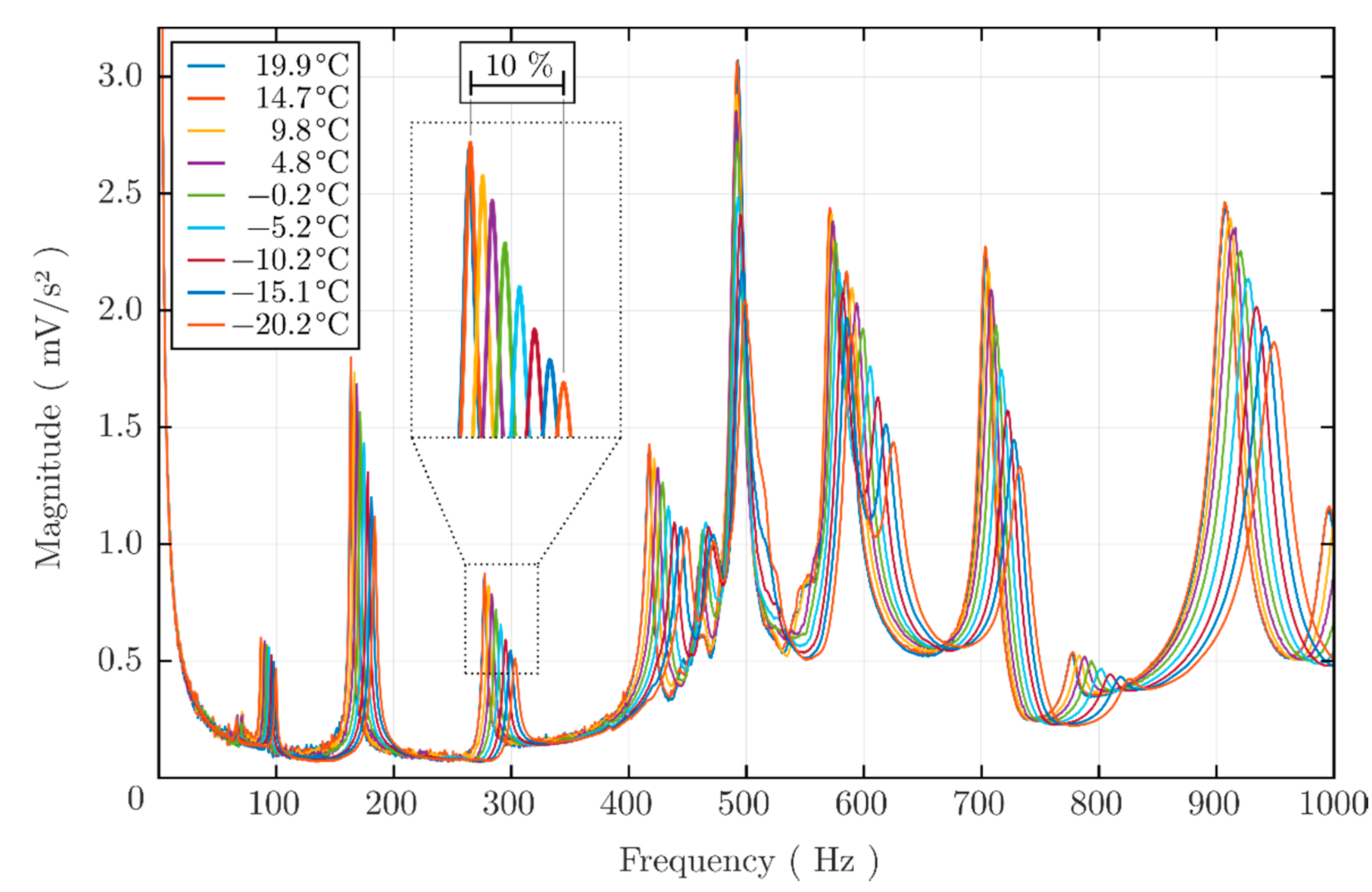
An experimental modal analysis is performed at nine different temperatures and the resulting frequency response spectra can be found in Figure 5. We observe an increase of all eight eigenfrequencies and an apparent stiffening of the rotor due to temperature decrease. This is due to the change of the mechanical properties of the resin system leading to relative changes of a maximum of 15%. The relative frequency deviation for the first five mode shapes is presented in Table 2.

3.2. Spatial Distribution

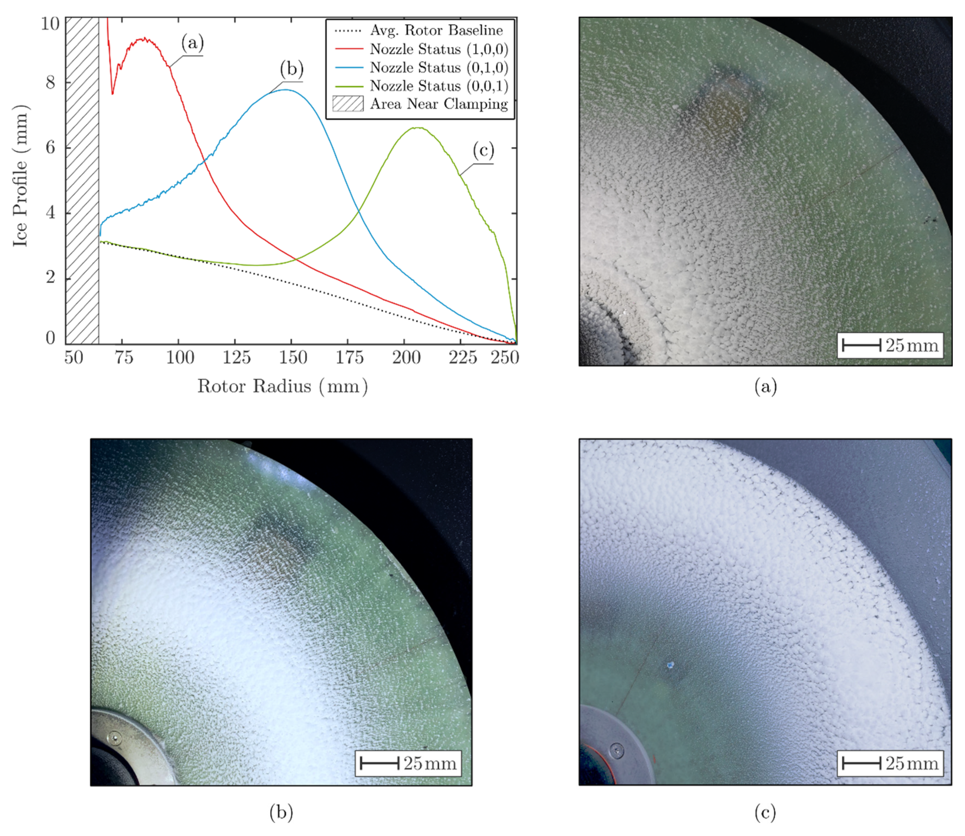
The spatial distribution of the ice along the rotor radius is briefly presented. The spatial distribution is achieved with the deployment of a three-nozzle setup. Each nozzle sprays in a specific range of the rotor radius. In Figure 6, the averaged profile line (rotor baseline) can be found. Because the line is evaluated with regards to a reference line, negative values at the left side near the clamping (radius 60–120 mm) are caused by the fact that the rotor has an uneven surface. The clamping covers an area with a radius of approximately 50 mm and is, therefore, not considered in the graph. Due to the elevated position of the clamping, it creates a flow barrier at close range and, thus, increases unintended ice accumulation at the edge. This area is, therefore, hatched in the figure.
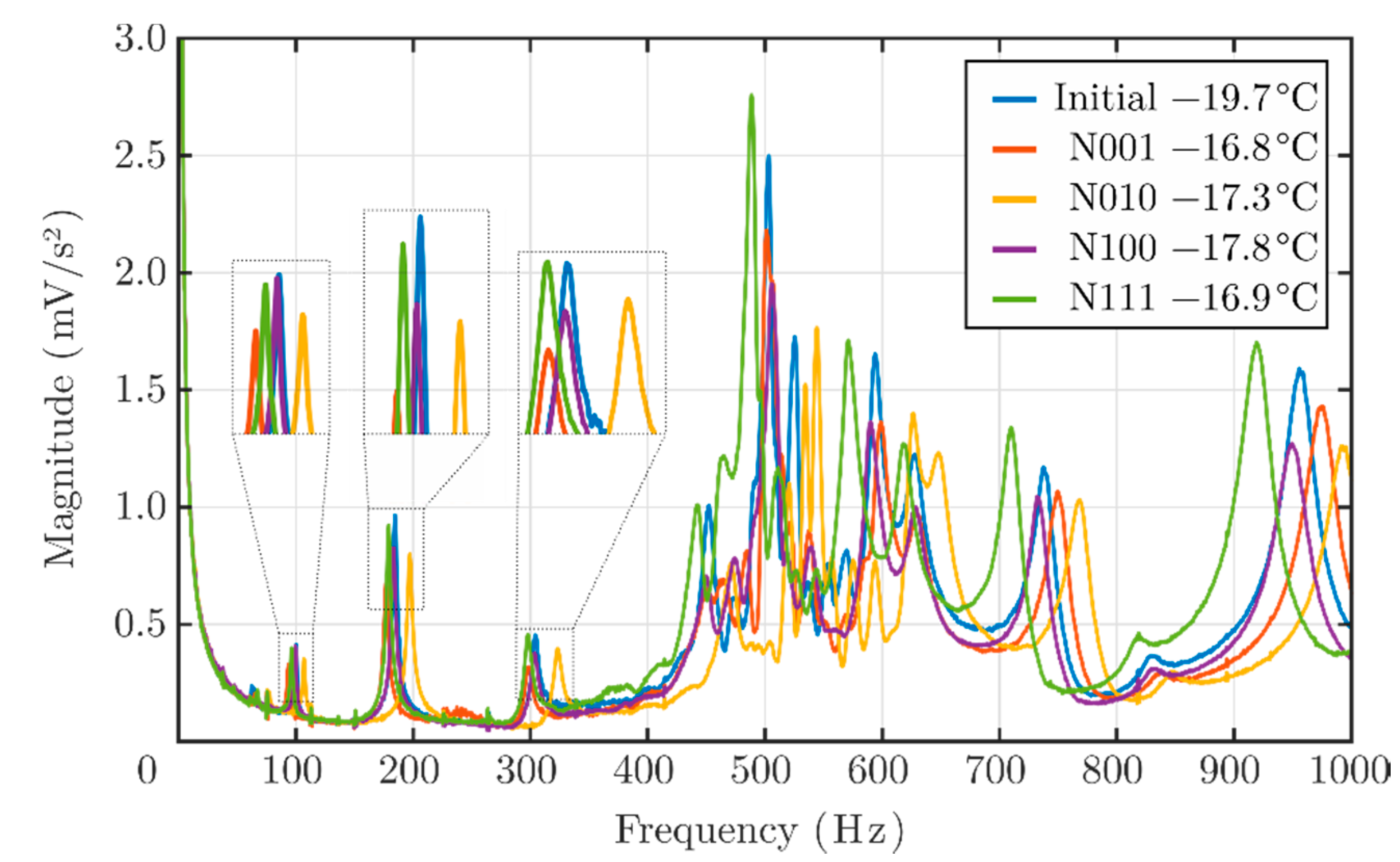
The changes in the modal properties, caused by different icing conditions, show a strong dependence on the ice distribution as well as on the ice thickness. Specifically, decreasing natural frequencies can be observed for all mode shapes as the ice accumulates at the rotor surface with the nozzle setup (1, 1, 1). In Table 3, the frequency deviation for the three spate nozzle configurations can be found, and they are also depicted in Figure 7. Since the temperature equilibrium varied between measurements depending on the ambient conditions, the natural frequencies in the initial state also differed from those in Table 2, and are, therefore, not specifically listed here. Due to the fluctuations in the actual ice thickness, the shifts of the natural frequency are listed together with the corresponding maximum thickness value.
An ice increase at the outer rotor radius, Figure 6 (left), causes decreasing eigenfrequencies for the first four eigenmodes, due to the maximum deflection of the corresponding mode shapes and the mass increase in the same area. Mode shapes containing nodal lines in the middle perimeter of the rotor do not exhibit any drastic frequency shifts.

3.3. Dependencies Between Ice Accumulation and Modal Properties

The interdependency between ice accumulation and the shift of the natural frequencies is investigated. It has to be mentioned that the equilibrium temperature was approximately −17 °C due to the air stream ejected by the nozzles. In order to stop the icing process, due to the system design, the hoses first had to be drained of any residual water to prevent the nozzles from freezing. This made it necessary to keep the system running with open valves, which resulted in small ice thickness deviations during the measurements. Therefore, the frequency shifts caused by the ice accumulation are evaluated with regards to the actual thickness and the maximum deviation at the time a measurement was performed. The results for five selected datasets are presented in Table 4.
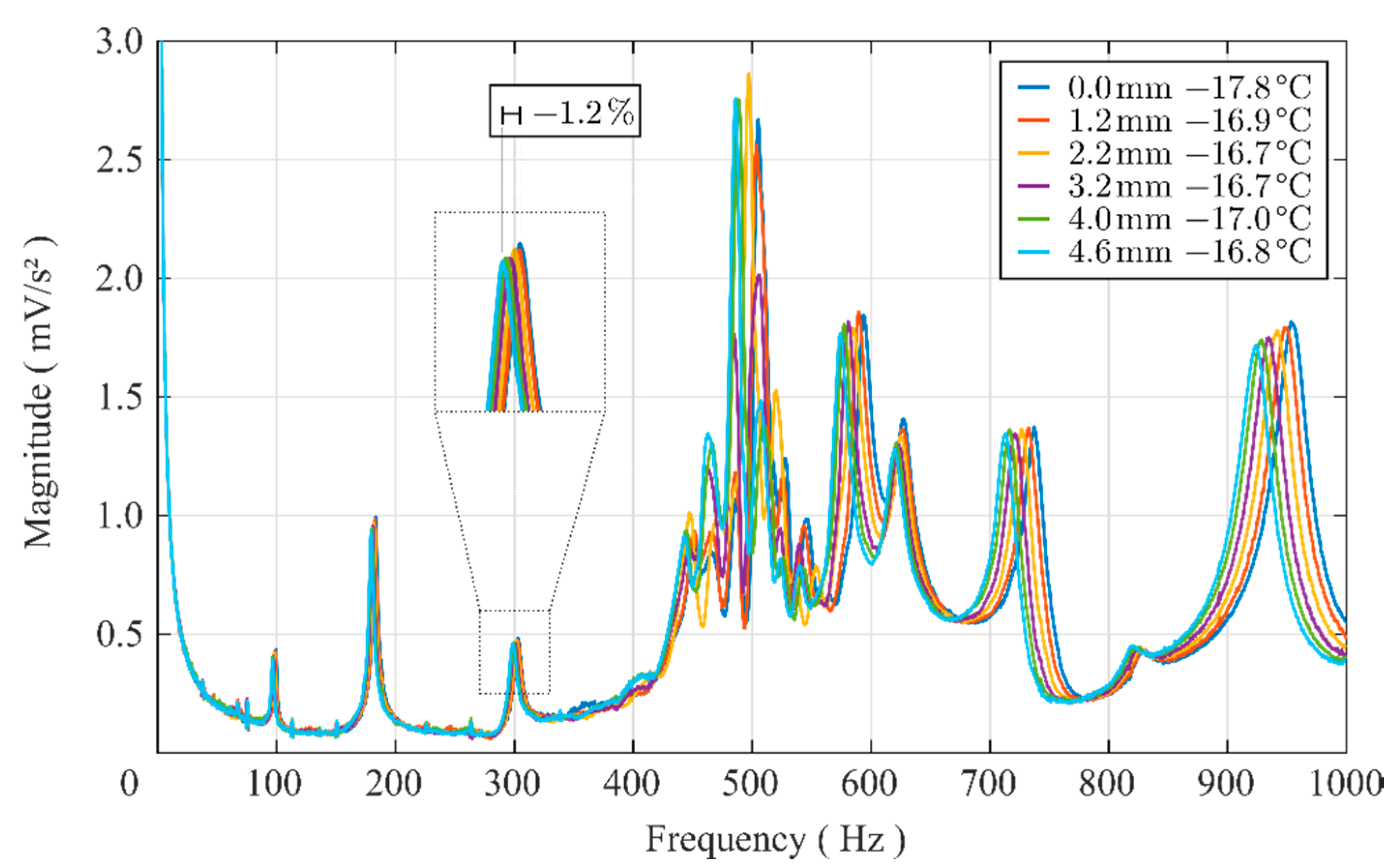
A noticeable decrease of natural frequencies for the majority of the first five eigenmodes can be observed. This trend corresponds to the expectations and information from the literature [20], according to which, the frequencies have to decrease as the mass increases. The fifth eigenmode shows non-monotonic behaviour, which indicates complex effects that need further investigation. The acquired spectra are presented in Figure 8, in which similar tendencies can be observed also for higher modes in the range of 550 and 1000 Hz. Modes that lie in between 450 and 550 Hz, in which the fifth eigenmode is also found, show a rather complex behaviour. The stiffness of the ice itself and the increase of mass cause opposing effects resulting in non-monotonic shifts of the natural frequencies and modal damping ratio.

4. Discussion

The goal of this paper was to present the results of an experimental study that investigated the changes in the modal properties of composite rotor blades under icing conditions. Therefore, various icing conditions were simulated using a generic GFRP rotor disc within a climate chamber. A water spray system was utilised to generate different icing conditions on the rotor surface. As a reference, the effects of environmental conditions such as temperature changes were investigated. It has been evident that temperature changes cause significant changes in the modal properties of fibre reinforced plastics. The stiffening of the resin due to the cold temperatures increases the natural frequencies percentagewise in the multi-digit range. The numerical values are reproducible and stand out clearly from the noise. Static measurements show a good peak to noise ratio of three to four, which is due to the high sensitivity of the accelerometers. The main contribution to noise was caused by electrical interference generated by the operation of the electric motor dropping the ratio to one to two. However, the noise is in a clearly definable frequency range in the higher kilohertz range and can, therefore, be eliminated by filters such as low pass and moving average, providing clear frequency spectra. The results also show clearly distinguishable frequency shifts when the icing conditions are examined separately.
To correlate changes in modal properties and ice accumulation, a laser scanning profiler was used to measure the ice distribution along the rotor circumference. The accuracy of the laser is accurate to a fraction of a millimetre and provides ice thickness profiles that enable results with good correlation. The icing conditions presented in this paper are also in good agreement with those from [4], in which rime ice was determined to be the usual type of icing on rotor blades.

5. Conclusions

The presented rotor icing test rig has been assembled and successfully operated for multiple temperatures. It has been proved that different types of ice can be generated regarding the ice thickness and distribution. An online experimental modal analysis under different rotational speeds was also successfully conducted and high-quality frequency spectra have been presented.
Complex phenomena have also been identified. For example, a non-monotonic change of the eigenfrequencies is observed and is investigated as a function of three parameters, mainly the temperature change and the ice accumulation and ice distribution. Future investigations will focus on the apparent stiffening of the rotor due to changes in temperature, ice type, and ice distribution, as well as centrifugal loads. Specifically, the change of the type of ice due to fluctuating sub-zero temperatures may also have an important effect on the structural dynamic behaviour of composite rotors. The distinction of the different types of frequency shifts when combining these several effects is still a challenge. Artificial neural networks have proven useful for multi feature extraction in other topics and will be considered for further investigations.

Author Contributions

Conceptualization, A.F. and M.G.; Data curation, M.N.; Funding acquisition, A.F. and M.G.; Investigation, A.F. and M.N.; Methodology, A.F. and D.B.; Project administration, M.D. and M.G.; Resources, M.D., D.B. and M.G.; Software, M.N.; Supervision, M.G.; Validation, A.F.; Visualization, M.N.; Writing—original draft, A.F. and M.N.; Writing—review and editing, M.D., D.B. and M.G. All authors have read and agreed to the published version of the manuscript.

Funding

The authors would like to express their gratitude for the financial support from the Deutsche Forschungsgemeinschaft (funding code GU 614/14−1).

Conflicts of Interest

The authors declare no conflict of interest. The funders had no role in the design of the study; in the collection, analyses, or interpretation of data; in the writing of the manuscript; or in the decision to publish the results.

References

  1. GWEC. Global Wind Report 2018. Available online: https://gwec.net/global-wind-report-2018/ (accessed on 5 May 2020).
  2. Faulstich, S.; Hahn, B.; Tavner, P.J. Wind turbine downtime and its importance for offshore deployment. Wind Energy 2011, 14, 327–337. [Google Scholar] [CrossRef]
  3. Macklin, W.C. The density and structure of ice formed by accretion. Q. J. R. Meteorol. Soc. 1962, 88, 30–50. [Google Scholar] [CrossRef]
  4. Li, Y.; Wang, S.; Liu, Q.; Feng, F.; Tagawa, K. Characteristics of ice accretions on blade of the straight-bladed vertical axis wind turbine rotating at low tip speed ratio. Cold Reg. Sci. Technol. 2018, 145, 1–13. [Google Scholar] [CrossRef]
  5. Bredesen, R.E.; Drapalik, M.; Butt, B. Understanding and acknowledging the ice throw hazard—Consequences for regulatory frameworks, risk perception and risk communication. J. Phys. Conf Ser. 2017, 926, 12001. [Google Scholar] [CrossRef]
  6. Kostka, P.; Holeczek, K.; Filippatos, A.; Hufenbach, W. Integration of Health Monitoring System for Composite Rotors. In Proceedings of the 18th International Conference on Composite Materials (ICCM18), Jeju Island, Korea, 21–26 August 2011. [Google Scholar]
  7. Kostka, P.; Filippatos, A.; Höhne, R.; Hufenbach, W. A Simulation-Based Monitoring of a Composite Plate Using an Integrated Vibration Measurement System. KEM 2013, 569, 64–71. [Google Scholar] [CrossRef]
  8. Filippatos, A.; Gude, M. Influence of gradual damage on the structural dynamic behaviour of composite rotors: Experimental investigations. Materials 2018, 11, 2421. [Google Scholar] [CrossRef] [PubMed] [Green Version]
  9. Brenner, D. Experience with De-Icing Systems, Noise and Vibrations Evoked by Ice Accretion. In Proceedings of the Winterwind Conference, Skellefteå, Sweden, 8 February 2017. [Google Scholar]
  10. Brenner, D. Determination of the actual ice mass on wind turbine blades. In Proceedings of the Winterwind Conference, Åre, Sweden, 10 February 2016. [Google Scholar]
  11. Brenner, D. 1500 operational Years of Icing on Wind Turbines—A Long Term Study. In Proceedings of the International Wind Energy Conference, Piteå, Sweden, 3–4 February 2015. [Google Scholar]
  12. Merizalde, Y.; Hernández-Callejo, L.; Duque-Perez, O.; Alonso-Gómez, V. Maintenance Models Applied to Wind Turbines. A Comprehensive Overview. Energies 2019, 12, 225. [Google Scholar] [CrossRef] [Green Version]
  13. Tchakoua, P.; Wamkeue, R.; Ouhrouche, M.; Slaoui-Hasnaoui, F.; Tameghe, T.; Ekemb, G. Wind Turbine Condition Monitoring: State-of-the-Art Review, New Trends, and Future Challenges. Energies 2014, 7, 2595–2630. [Google Scholar] [CrossRef] [Green Version]
  14. Bassett, K.; Carriveau, R.; Ting, D.S.-K. Vibration Analysis of 2.3 MW Wind Turbine Operation Using the Discrete Wavelet Transform. Wind Eng. 2010, 34, 375–388. [Google Scholar] [CrossRef]
  15. He, G.; Ding, K.; Li, W.; Jiao, X. A novel order tracking method for wind turbine planetary gearbox vibration analysis based on discrete spectrum correction technique. Renew. Energy 2016, 87, 364–375. [Google Scholar] [CrossRef]
  16. Mughal, U.; Virk, M.; Mustafa, M. State of the Art Review of Atmospheric Icing Sensors. Sens. Transducers 2016, 198, 2–15. [Google Scholar]
  17. Kim, H.C.; Giri, P.; Lee, J.R. A real-time deflection monitoring system for wind turbine blades using a built-in laser displacement sensor. In Proceedings of the 6th European Workshop on Structural Health Monitoring (EWSHM 2012), Dresden, Germany, 3–6 July 2012; Curran Associates Inc.: Red Hook, NY, USA, 2016; pp. 1010–1018, ISBN 9781510829480. [Google Scholar]
  18. Giri, P.; Lee, J.R. In Situ Blade Deflection Monitoring of a Wind Turbine Using a Wireless Laser Displacement Sensor Device within the Tower. KEM 2013, 558, 84–91. [Google Scholar] [CrossRef]
  19. Yang, J.; Peng, C.; Xiao, J.; Zeng, J.; Yuan, Y. Application of videometric technique to deformation measurement for large-scale composite wind turbine blade. Appl. Energy 2012, 98, 292–300. [Google Scholar] [CrossRef]
  20. Cormier, L.; Joncas, S.; Nijssen, R.P.L. Effects of low temperature on the mechanical properties of glass fibre-epoxy composites: Static tension, compression, R = 0.1 and R = −1 fatigue of ±45° laminates. Wind Energy 2016, 19, 1023–1041. [Google Scholar] [CrossRef]
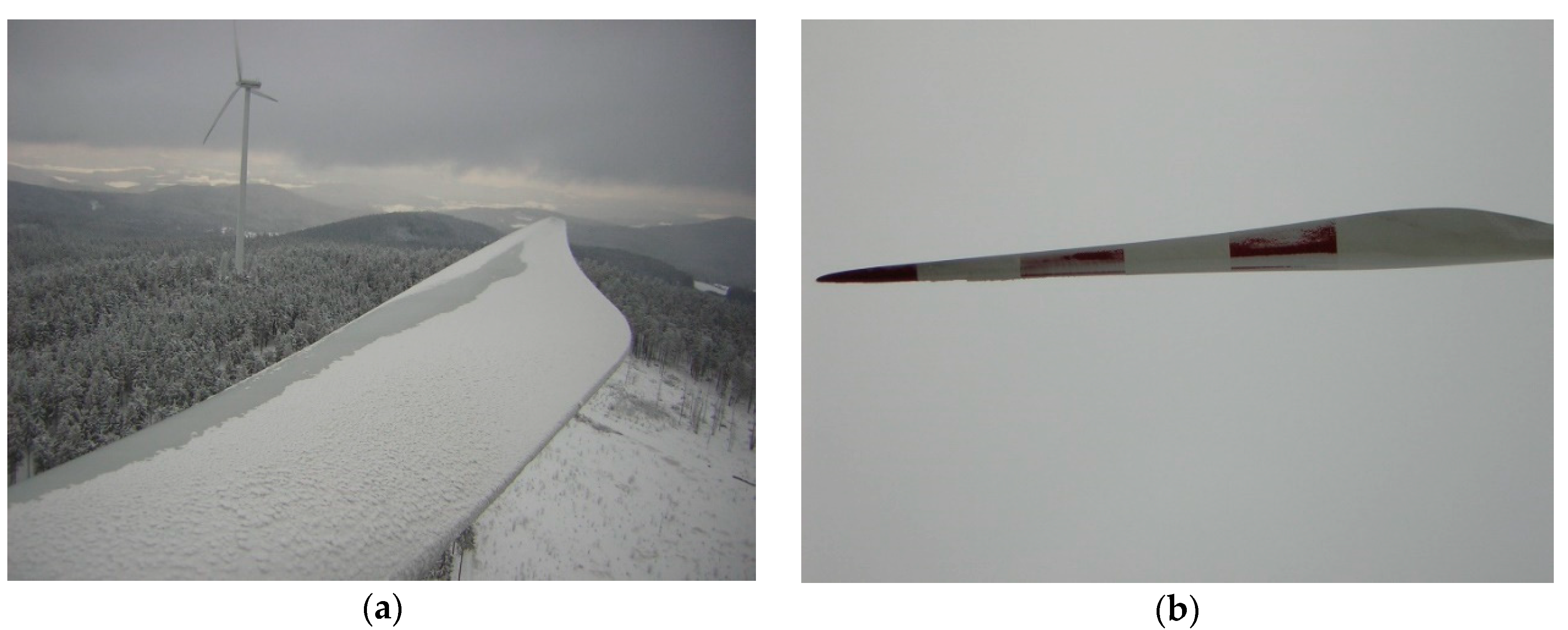
Figure 1. Typical icing conditions on the rotor blade of a glass fibre-reinforced plastic (GFRP) wind turbine,(a) top view and (b) rear view with ice accumulation.
Applsci 10 05063 g001
Figure 2. Fibre alignment and dimensions of the radial and tangential sub-preform types with the total layup of the GFRP rotor (a). Placement of the actuators and sensors (b).
Applsci 10 05063 g002
Figure 3. Picture of the nozzle setup on the test bench (a) and the corresponding schematic illustration (b).
Applsci 10 05063 g003
Figure 4. Illustration of the test bench with its components that is used to create icing on a GFRP rotor.
Applsci 10 05063 g004
Figure 5. Response spectra of measurements conducted at different temperatures.
Applsci 10 05063 g005
Figure 6. Thickness profile of ice accumulation along the radius of the rotor at constant rotational speed using three different nozzle configurations to form ice on the inner radius (a), in the centre (b) and on the outer radius of the rotor (c).
Applsci 10 05063 g006
Figure 7. Response spectra of measurements conducted with different nozzle setups.
Applsci 10 05063 g007
Figure 8. Frequency spectra illustrating the change in natural frequencies due to ice accumulation along the rotor radius, generated by opening all three nozzles (1, 1, 1).
Applsci 10 05063 g008
Table 1. Performed measurements at the composite rotor with different parameters.
Number of MeasurementNozzles Status (0:Closed, 1:Open)Temperature (°C)Rotational Velocity (RPM)Average Ice Thickness (mm)
M01–M09(0, 0, 0)20, 15, …−2000.0
M10–M15(1, 1, 1)−201000.0 to 4.5
M16–M20(0, 0, 1)−20100to 5.7
M21–M25(0, 1, 0)−201000.0 to 6.9
M26–M30(1, 0, 0)−20100to 11.7
Table 2. Relative shift of the first five natural frequencies (EF 1 to EF 5) under different temperatures; the values are peak estimates of the averaged response spectra.
MeasurementTemperatureEF 1EF 2EF 3EF 4EF 5
(°C)87.6 Hz164.9 Hz278.3 Hz418.0 Hz486.5 Hz
M0119.90.00%0.00%0.00%0.00%0.00%
M039.84.29%3.52%2.61%2.05%0.48%
M05−0.28.23%6.79%5.08%4.12%1.38%
M07−10.212.02%9.99%7.64%6.23%2.53%
M09−20.215.30%12.20%10.11%8.39%3.78%
Table 3. Relative shift of the first five natural frequencies under different ice distributions, the values are peak estimates of the averaged response spectra.
Nozzles Status (0:Closed, 1:Open)Temperature (°C)Max. Ice ThicknessEF1EF2EF3EF4EF5
(0, 0, 1)−16.8~5.7 mm−7.89%−6.01%−4.54%−3.40%−0.70%
(0, 1, 0)−17.3~6.9 mm5.82%5.98%5.67%0.84%5.65%
(1, 0, 0)−17.8~11.7 mm−2.00%−1.36%−0.89%0.67%1.88%
(1, 1, 1)−16.9~4.6 mm−2.86%−2.02%−1.49%−1.71%−0.67%
Table 4. Relative shift of the first five natural frequencies under ice accumulation at approximately −17 °C.
Average Ice ThicknessEF1EF2EF3EF4EF5
87.6 Hz164.9 Hz278.3 Hz418.0 Hz486.5 Hz
~1.2 mm−0.68%−0.33%−0.10%−0.09%0.17%
~2.2 mm−1.25%−0.93%−0.43%−0.73%0.82%
~3.2 mm−2.01%−1.26%−0.79%−0.84%−0.47%
~4.0 mm−2.39%−1.64%−1.12%−1.44%0.13%
~4.6 mm−2.86%−2.02%−1.49%−1.71%−0.67%