Article

NO Separation Characteristics in Integrated Electromigration Membrane Reactor

Department of Environmental Science and Engineering, Wuhan University, Wuhan 430079, China
*
Author to whom correspondence should be addressed.
Appl. Sci. 2020, 10(15), 5071; https://doi.org/10.3390/app10155071
Submission received: 13 June 2020 / Revised: 10 July 2020 / Accepted: 20 July 2020 / Published: 23 July 2020
(This article belongs to the Section Environmental Sciences)

Abstract

:
An integrated electromigration membrane absorption method has been proposed for the separation of NO from simulated mixed gas. The experiments were conducted to investigate the effect of discharge voltage, gas flow rate, inlet concentrations, and absorbents on the NO separation efficiency and total mass transfer coefficient in the integrated electromigration membrane reactor. The experimental results demonstrated that the NO separation efficiency and total mass transfer coefficient increased with the increase in the applied discharge voltage of the integrated electromigration membrane reactor. Regardless of discharge or not, the separation efficiency of NO continuously decreased with the increase in the gas flow rate and inlet concentration of NO in the experimental process. The total mass transfer coefficient of NO increased first and then decreased with an increase in the gas flow rate, while it decreased with an increase in NO inlet concentration. Compared with the membrane absorption without discharge voltage under the condition tested, at a discharge voltage of 18kV, the NO separation efficiency and the total mass transfer coefficient increased by 48.7% and 9.7 times, respectively.

Graphical Abstract

1. Introduction

With the frequent occurrence of pollution and the aggravation of resource shortage, pollutant control technology has been investigated from pollution removal to the resource utilization of pollutants [1]. The NOx released from fossil fuel combustion causes bad environmental questions, such as acid rain, haze, and photochemical smog, which are harmful to human health and the ecological environment [2,3]. At present, the technology of selective non-catalytic reduction denitrification (SNCR) and selective catalytic reduction denitrification (SCR), which reduces NOx emission, shows a high removal efficiency. However, they also are accompanied by some technical difficulties, such as large equipment, air preheater clog, trashy catalyst disposal, and so on [4,5,6]. Thus, it has been important to develop new denitrification technologies or improve the existing technology for stricter emission standards [3,7].
The membrane gas separation method, which takes the membrane fiber medium as the separation interface, is a new type of gas absorption process with good application prospects. It has the advantages of low-energy consumption, compact structure, simple operation, and strong selectivity, and effectively overcomes the disadvantages of flooding, channeling, and foaming in traditional wet absorption equipment by non-contact between gas and liquid [8]. In recent years, a series of experiments of membrane absorption have been carried out to separate the acid gases of hydrogen sulfide (H2S), SO2, NOx. For example, Qi [9,10] studied the mass transfer process from the gas phase to liquid phase for H2S, SO2, NH3, and CO2 in a membrane absorption reactor and measured the mass transfer coefficients of some gases. Rami et al. [11] studied the removal efficiency of hydrogen sulfide in natural gas by the membrane absorption method under high pressure. Sun et al. [12] researched the feasibility of SO2 removal by a hollow fiber membrane using seawater as an absorbent, and studied the effect of related parameters on its mass transfer coefficient. Zhang et al. [13] analyzed the effect of some parameters on the SO2 removal efficiency in a membrane contactor. Kartohardjono et al. [14] and Wang et al. [15] carried out an investigation on the characteristics of NOx removal by membrane absorption. Among these studies, the transfer of gas molecules through a membrane mainly depends on the concentration difference and the pressure difference of gas in the two sides of the membrane [16], which is accompanied by high gas driving force and large unit gas membrane area for achieving a high gas separation efficiency [8].
Electromigration, which uses electric field force as the driving force, is an effective separation method to concentrate or separate specific components from the mixture. The method of using electric field force as the driving force has been widely used in industrial production and has shown an excellent technical and economic performance in applications such as electrodialysis, electro-ultrafiltration [17], and electrostatic precipitators [18]. However, few studies have reported enhancing the gas separation efficiency by electromigration in membrane absorption. In view of the above, this paper proposed an integrated electromigration membrane separation process which organically combined plasma technology, electromigration, membrane separation, and chemical absorption. It analyzed the separation mechanism of NO in an integrated electromigration membrane separation reactor. The effect of discharge voltage, gas flow rate, inlet concentration, and absorbents on the separation efficiency and total mass transfer coefficient of NO were discussed. It is hoped that this research can provide new ideas and references for the development of gas separation technology.

2. Experiments

2.1. Experimental Methods

The schematic diagram of the experimental process is shown in Figure 1. The experimental apparatus mainly consisted of a gas distribution unit, an integrated electromigration membrane separation reactor, and a gas measurement system. The 230 × 50 × 60 mm rectangular reactor was made of polymethyl methaerylate (PMMA).
Discharge needle electrodes were placed evenly in the upper wall of the reactor and connected with an external negative high-voltage DC power supply. The grounding electrode made of a stainless steel plate was placed on the internal bottom of the reactor, which was filled with aqueous absorbent. A hydrophobicmicroporous membrane consisted of PVDF (polyvinylidene fluoride) and PTFE (Poly tetra fluoroethylene) with a pore size of 0.22 µm and the thickness of 150 µm was installed between the needle electrodes and the grounding electrode, parallel to the grounding electrode and dividing the reactor into two parts. A mixture gas of N2-NO provided by compressed steel cylinders went through the space between the needle electrodes and the membrane, while the aqueous absorbent continuously flowed through the space between the membrane and the grounding electrode at a constant flux of 65 mL·min−1. The treated gas was exhausted through a gas absorbing device. The inlet and outlet concentrations of NO were measured by a flue gas analyzer.

2.2. Process Description and Calculation

The separation process of NO in the integrated electromigration membrane reactor can be divided into three steps:
(1)
Formation of NO negative ions:
The N and O atoms in the NO molecule are hybridized with sp orbitals to form a б bond, a π bond, and a large two-center three-electron π 2 3 bond which contains an unpaired electron. In the reactor, NO gas molecule collides with low-energy electrons are generated by gas discharge, capturing electrons to form NO negative ions, which can be briefly described as follows [19,20]:
e + NO NO ,
e + NO + M NO + M ,
( NO ) n + e ( 0 eV )   NO + ( n 1 ) · NO .
(2)
Separation of NO from simulated mixture gas:
Under the synergistic action of the concentration gradient and electric field force, the NO negative ions drift towards the interface of the gas membrane from the simulated mixture gas.
Because the membrane is set up in the electric field, the NO negative ions continue to migrate through the membrane pores into the absorbent liquid side of the membrane due to the grounding electrode, which is immersed in the absorption solution. The total mass transfer flux (N) in the process can be expressed as follows [21]:
N = D d C d x + v C ,
where C is the concentration of NO negative ions in the surface membrane; v is the migration velocity of negative ions in an electric field, v = μE, m·s−1; μ is the ion migration velocity at the unit electric-field intensity, m2V−1s−1; D is the gas diffusion coefficient, m2·s−1. In the coexistence process of gas diffusion and electromigration, according to Einstein’s equation, the relationship of the gas diffusion coefficient and its electromigration rate can be expressed as follows [22]:
μ D = e k T ,
where k is the Boltzmann constant, 1.38 × 10⁻²³ J/K; T is experimental temperature, K; e is the charge amount of an electron, 1.6 × 10⁻¹⁹ C.
In T < 25 °C, it can be concluded that the electromigration rate of an NO negative ion (µ) is about 39 times higher than its own diffusion coefficient (D). Thus, the effect of molecule diffusion on the NO separation efficiency is negligible. Therefore, the separation of NO in the reactor is mainly depended on the electromigration movement.
(3)
Absorption of NO in the absorption solution:
NO negative ions through the membrane are absorbed by aqueous solutions, such as NaClO2 or KMnO4/NaOH aqueous solution. The absorption reactions for NO removal can be briefly expressed as follows in the experimental process [23,24]:
NO ( g ) NO ( aq ) ,
NO + MnO 4 + 2 OH NO 2 + MnO 4 2 + H 2 O ,
NO 2 + 2 MnO 4 + 2 OH NO 3 + 2 MnO 4 2 + H 2 O ,
4 NO + 3 ClO 2 + 2 H 2 O 4 HNO 3 + 3 Cl .
In the study, the separation efficiency and the total mass transfer coefficient are used to evaluate the performance of the integrated electromigration membrane separation reactor on the NO separation from mixture gas, and are calculated by the following formulas [25,26] (Park et al. 2009; Peng et al. 2008):
η = C in C o u t C i n × 100 % ,
K = Q A ln ( C i n C o u t ) = Q A ln ( 1 1 - η ) ,
where η is the separation efficiency of NO, %; K is the total mass transfer coefficient of NO, m·s−1; Q is the gas flow rate, L·min−1; Cin and Cout are the inlet and outlet concentration of NO in the reactor, mg·m−3; A is the membrane surface area, m2.

3. Results and Discussion

3.1. Effect of Discharge Voltage on Separation Efficiency and Total Mass Transfer Coefficient

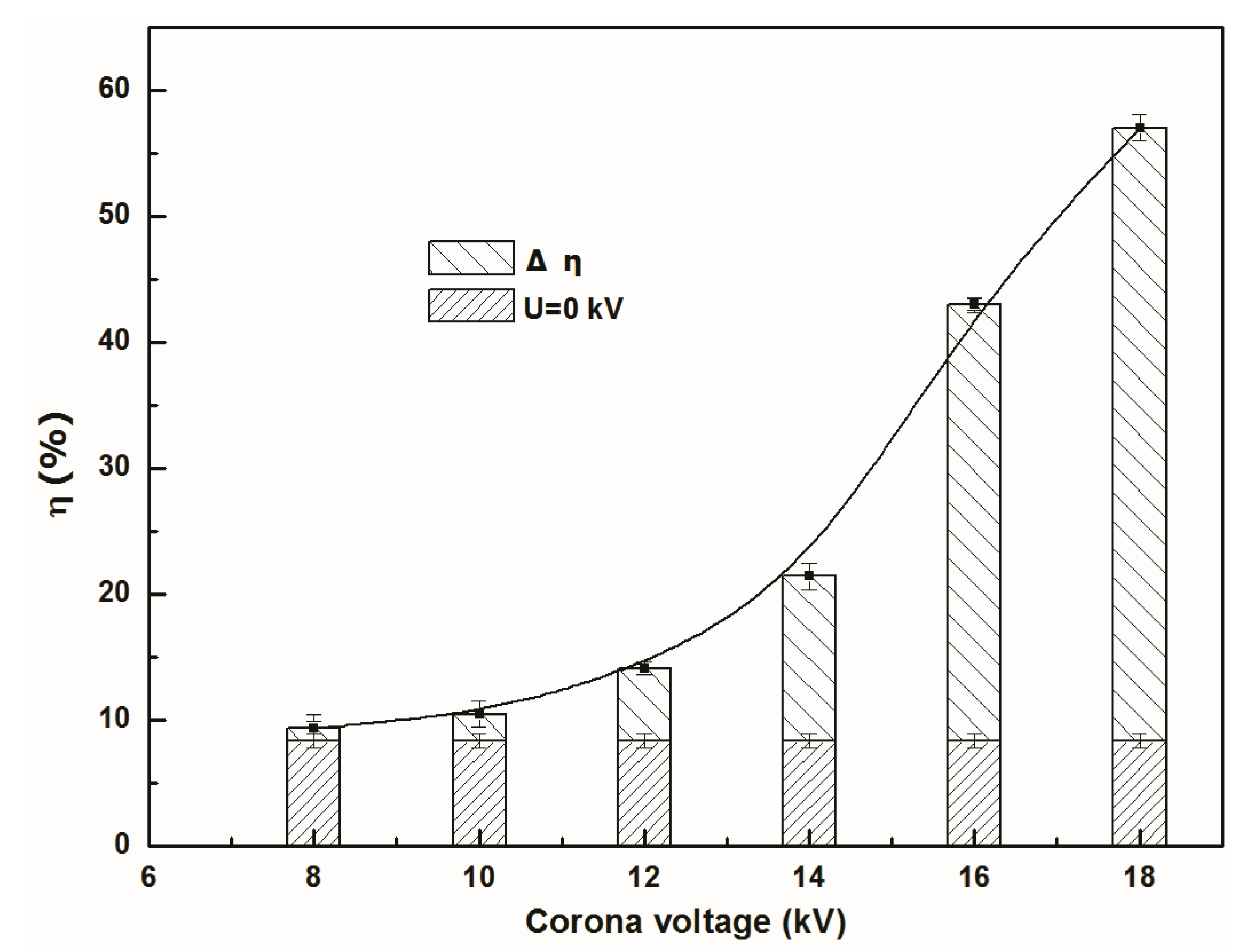
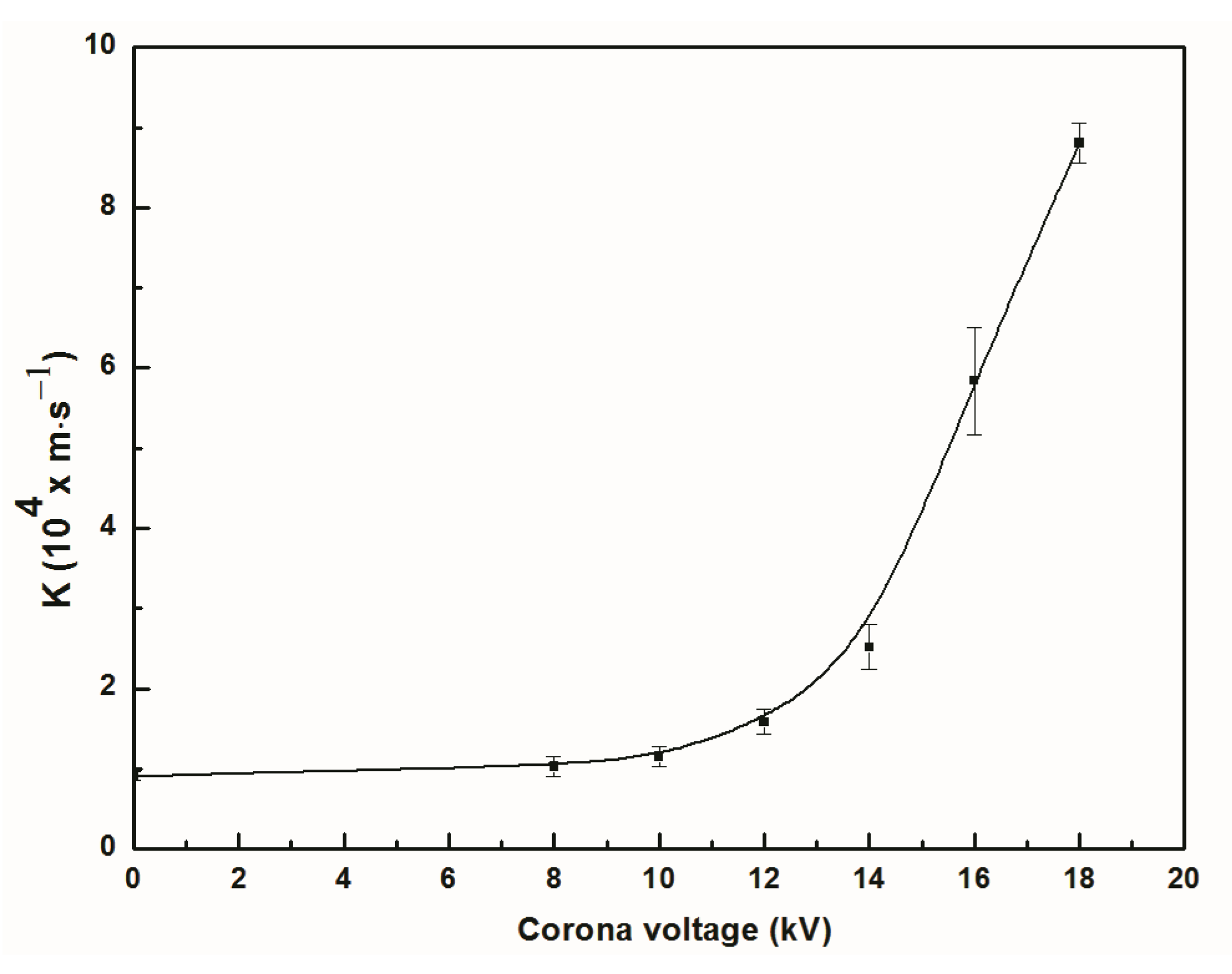
The effect of discharge voltage on the NO separation efficiency and total mass transfer coefficient is shown in Figure 2 and Figure 3. It can be seen from Figure 2 that the NO separation efficiency was related to the discharge voltage. When the discharge voltage increased from 8 to 18 kV, the NO separation efficiency first slightly rose and then rapidly increased. At an applied voltage of 18 kV, the separation efficiency was about 57%, which improved by 48.7% compared with the one without discharge. The formation of NO negative ions is related to the electron concentration in the reaction area [27] (Hajime Tamon 1996). When the discharge voltage was lower than 8 kV, the efficiency increment was lower than 1.05% compared with the efficiency without discharge, where few NO negative ions were formed due to the low electron concentration in the reaction space. While the discharge voltage exceeded the corona onset voltage, the electron amounts increased rapidly due to electron avalanche and prompted the formation of NO negative ions. Therefore, the NO separation efficiency increases rapidly with the increase in the discharge voltage [28]. When the discharge voltage was higher than 18 kV, the electric field was broken down. Therefore, the maximum discharge voltage was set at 18 kV. Similarly, the total mass transfer coefficient of NO increases with the increase in the discharge voltage (Figure 3). When the discharge voltage increases from 0 to 18 kV, the total mass transfer coefficient of NO increases from 0.91 × 10⁻⁴ to 8.81 × 10⁻⁴ m·s−1; the total mass transfer coefficient at discharge voltage of 18 kV is about 9.7 times than one without applied voltage. This may be because a high discharge voltage caused an increase in the amount and electromigration velocity of the NO negative ions, which not only prompted NO absorption but also reduced the mass transfer resistance in the gas phase.

3.2. Effect of Gas Flow Rate on Separation Efficiency and Total Mass Transfer Coefficient

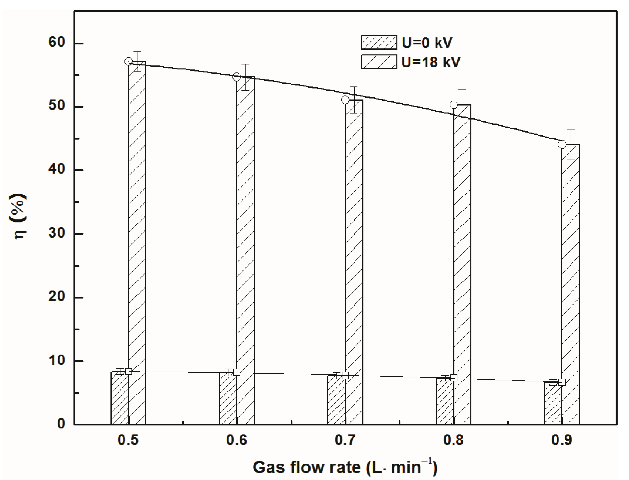
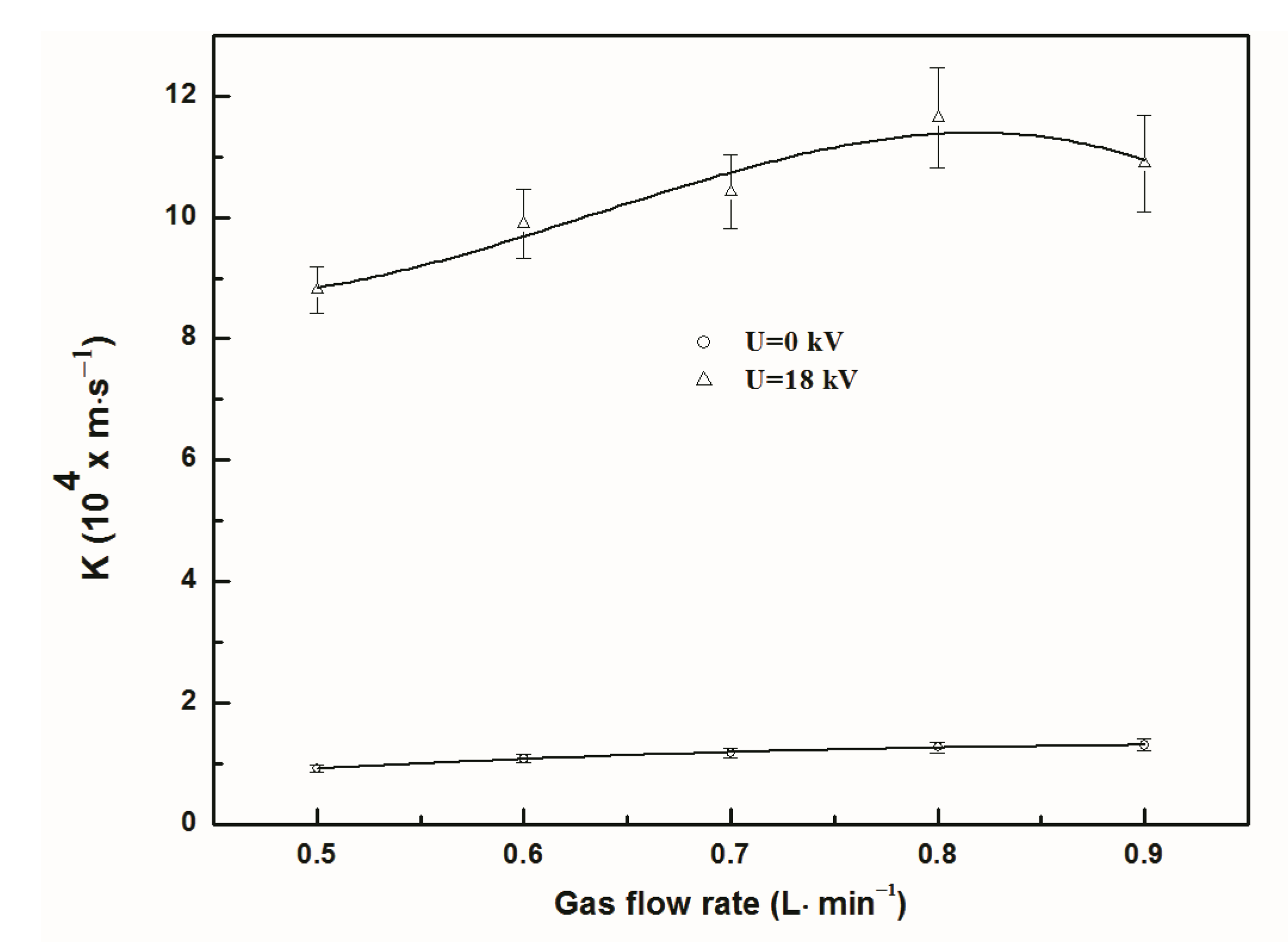
The effect of the gas flow rate on the NO separation efficiency and total mass transfer coefficient with discharge and non-discharge is demonstrated in Figure 4 and Figure 5. It can be seen that the NO separation efficiency decreased regardless of whether there was discharge or not when the gas flow rate increased from 0.5 to 0.9 L·min−1. This tendency was consistent with the Wang et al. [15] research result of absorbing NO in a membrane reactor. It also can be seen from Figure 4 that the decreasing trend in separation efficiency during discharge was more pronounced than the trend without discharge, when the gas flow rate increased. When the gas flow rate increased from 0.5 to 0.9 L·min−1, the NO separation efficiency at 0kV discharge voltage decreased from 8.37% to 6.7%, and its reduction value was about 1.67%, while the one at 18 kV discharge voltage decreased from 57.1% to 44.0%, and its reduction value was about 13%. This may be because that NO separation mainly owed to the NO electromigration movement, and the increase in the gas flow rate not only reduced the residence time of NO gas in the reactor but also reduced the formation probability and proportion of the NO negative ions under the discharge condition, so that the NO separation efficiency reduces significantly when the gas flow rate increases. Unlike separation efficiency, the total mass transfer coefficient of NO increased first and then decreased as the gas flow rate increased at an 18 kV discharge voltage, and its maximum value was 11.6 × 10⁻⁴ m·s−1 at the given gas flow rate of 0.8 L·min−1 (Figure 5). Meanwhile, it had no significantly change with the increase in the gas flow rate under the non-discharge condition. This may be because the increase in the gas flow rate reduces the mass transfer resistance of the gas-phase, as well as reducing the residence time of NO gas in the reactor. The former improved the total mass transfer coefficient based on the resistance-in-serials equation of the membrane process, while the latter reduced the NO separation efficiency and mass transfer coefficient, as can be seen from Equation (4).

3.3. Effect of Inlet Concentration on Separation Efficiency and Total Mass Transfer Coefficient

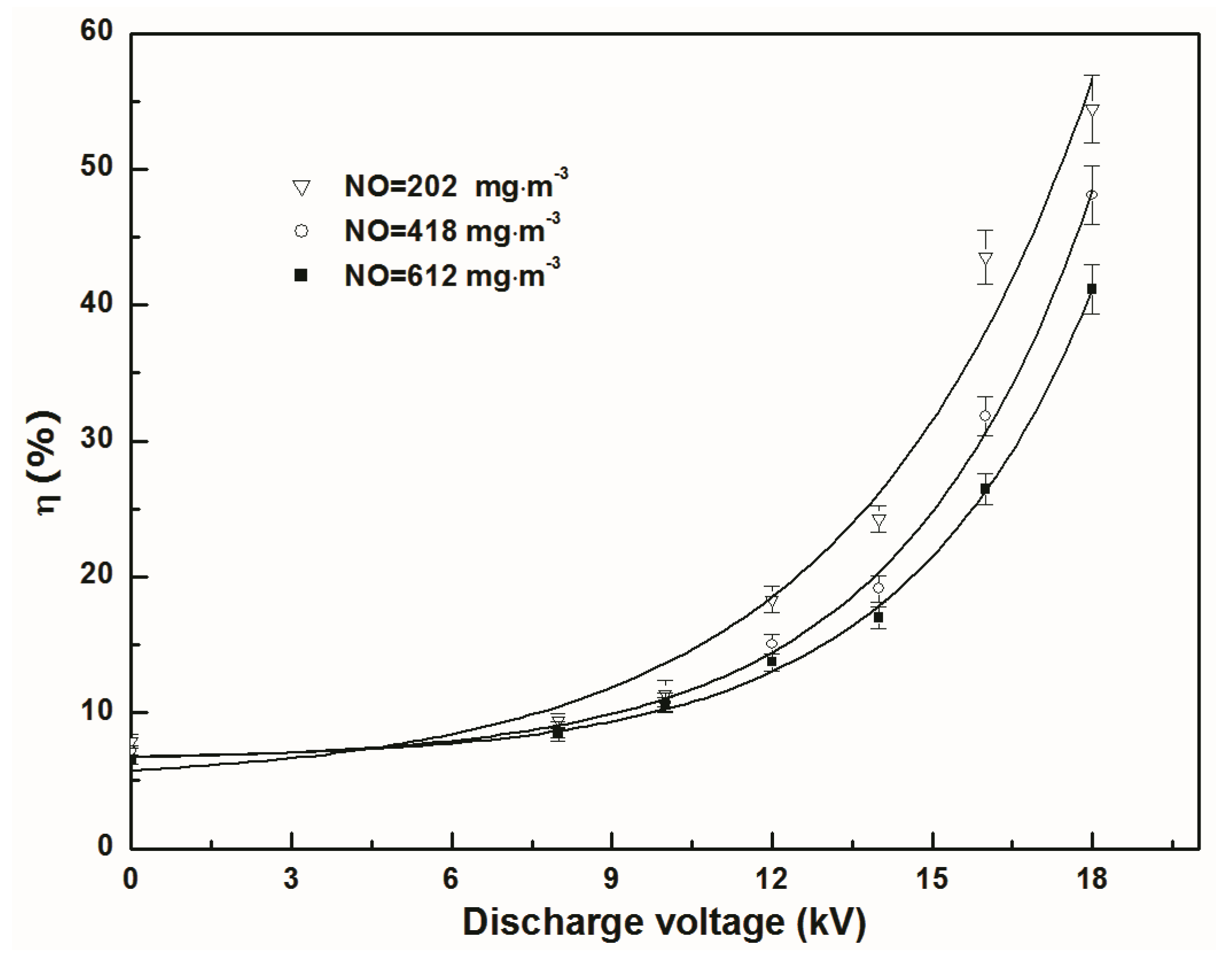
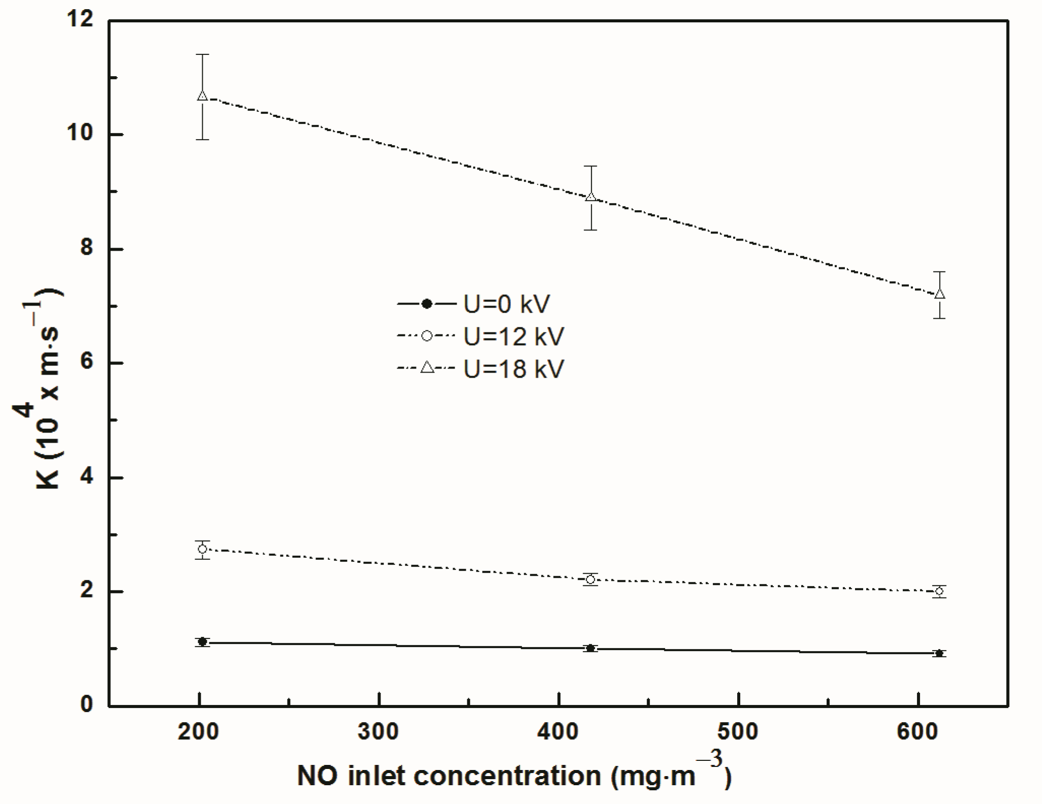
The effect of the NO inlet concentration on the NO separation efficiency and total mass transfer coefficient was shown in Figure 6 and Figure 7, respectively. It can be observed in Figure 6 that the separation efficiency decreased with the increase in the NO inlet concentration under the experimental conditions. When the NO inlet concentration increased from 202 to 612 mg·m−3, the NO separation efficiency decreased from 56.4% to 41.2% at an 18 kV discharge voltage. This is the reason why the increased amount of NO negative ions is less than the increased amount of NO molecules in the reactor with the increase in the NO inlet concentration. Some studies [29,30] have reported a similar changing rule in removing NO using other methods. It can be seen from Figure 7 that the total mass transfer coefficient of NO decreased with the increase in the inlet concentration. It also can be seen in Figure 7 with the increasing of inlet concentration that the total mass transfer coefficient decreased more significantly at a discharge voltage of 18 kV than at a discharge voltage of 12 kV. It may be the reason that the NO separation efficiency decreased as the NO inlet concentration increased (Equations (3) and (4)) [26].

3.4. Effect of Absorbent on no Separation Efficiency and Total Mass Transfer Coefficient

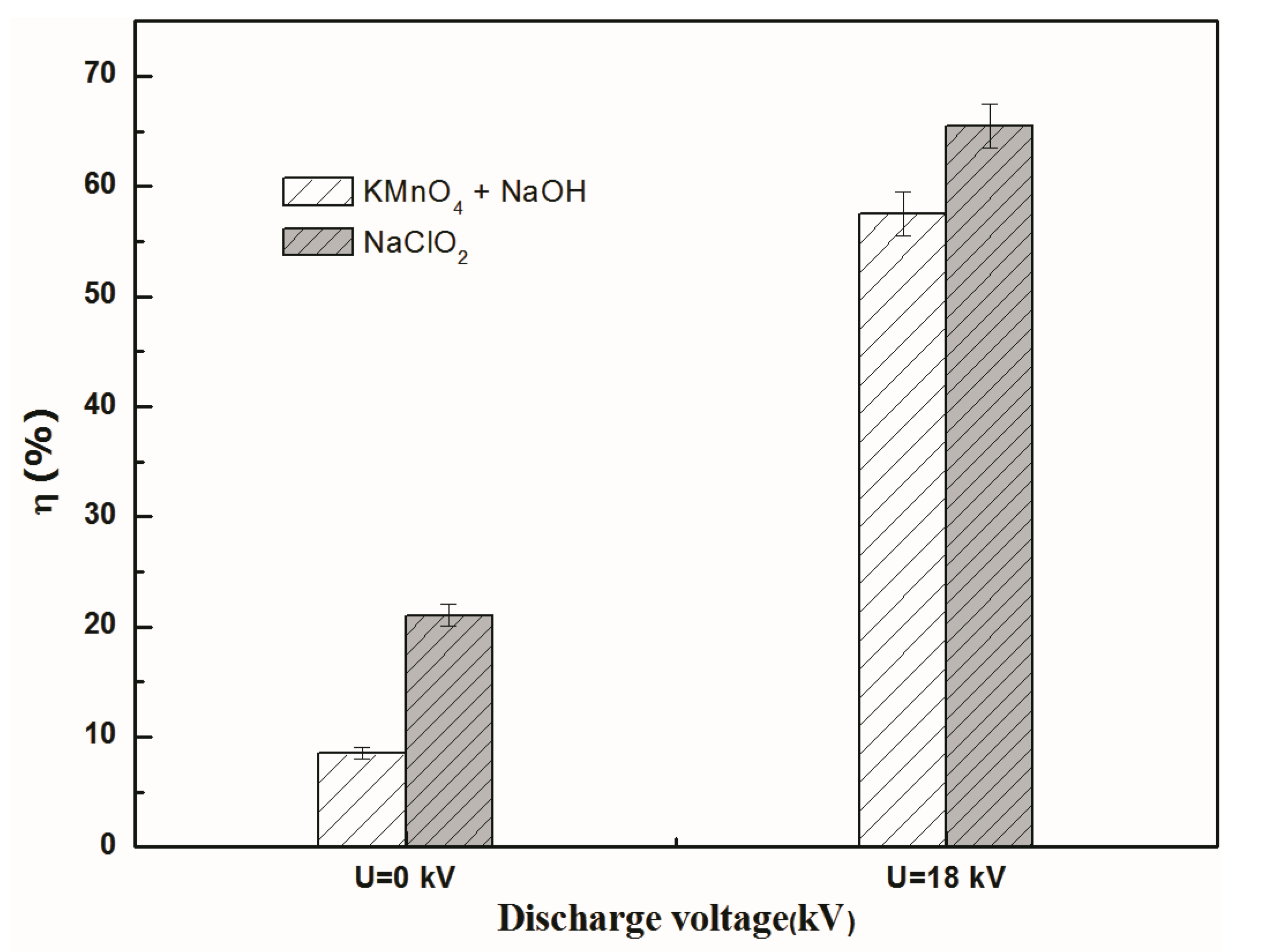
The effect of two different absorbents, NaClO2 and KMnO4/NaOH, on the separation efficiency and total mass transfer coefficient is shown in Figure 8 and Figure 9. It can be seen from Figure 8 and Figure 9 that the corona discharge could improve the NO separation efficiency and total transfer coefficient, and the separation efficiency and total transfer coefficient with NaClO2 as the absorbent were higher than those with KMnO4/NaOH as the absorbent in the condition of discharge or no discharge. This may be due to three reasons: (i) the migration of NO negative ions improved the absorption efficiency in the electric field; (ii) the reaction rate of NaClO2 with NO was higher than that of KMnO4/NaOH with NO [23,29,31,32,33] (Chu et al. 2000; Fang et al. 2013; Brogren et al. 1997; Zhong et al. 2009; Chien et al. 2005); (iii) a higher absorption rate can reduce the mass transfer resistance in the liquid phase when the gas flow rate remains fixed and the other experimental conditions are the same.

4. Conclusions

The following conclusions can be drawn from the experimental research:
(1)
The integrated electromigration membrane separation method can effectively separate NO from NO-N2 mixture gas. At the discharge voltage of 18kV, the separation efficiency of NO in the reactor was about 57%. It increased by 48.7%, and the total mass transfer coefficient of NO was raised 9.7 times compared with the one in membrane absorption process without discharge.
(2)
The electromigration of NO negative ions can enhance NO separation and mass transfer. “When the applied voltage is higher onset voltage, higher discharge voltage has greater separation efficiency and total mass transfer coefficient of NO under experimental” condition.
(3)
Regardless of discharge or not, the separation efficiency of NO continuously declined with the increase of gas flow rate and inlet concentration of NO. The total mass transfer coefficient of NO increased first and then reduced with the increase of gas flow rate, while it decreased with the increase of NO inlet concentration.

Author Contributions

Z.W.: Conceptualization, Supervision, Project administration, Writing—Reviewing and Editing. G.S.: Investigation, Data curation, Writing—Original draft preparation. All authors have read and agreed to the published version of the manuscript.

Funding

The work was supported by the National Natural Science Foundation of China (nsfc) under grant (No. 50278072).

Conflicts of Interest

The work described has not been submitted elsewhere for publication, and no conflict of interest exists in the submission of this manuscript.

References

  1. Hao, R.; Wang, X.; Zhao, X.; Xu, M.; Zhao, Y.; Mao, X.; Yuan, B.; Zhang, Y.; Gao, K. A novel integrated method of vapor oxidation with dual absorption for simultaneous removal of SO2 and NO: Feasibility and prospect. Chem. Eng. J. 2018, 333, 583–593. [Google Scholar] [CrossRef]
  2. Liu, Y.; Liu, Z.; Zhao, L.; Wang, Y.; Pan, J.; Wang, Q.; Zhang, J. Removal of NO in flue gas using vacuum ultraviolet light/ultrasound/chlorine in a VUV-US coupled reactor. Fuel Process. Technol. 2018, 169, 226–235. [Google Scholar] [CrossRef]
  3. Sun, Y.; Zwolińska, E.; Chmielewski, A.G. Abatement technologies for high concentrations of NOx and SO2 removal from exhaust gases: A review. Crit. Rev. Environ. Sci. Technol. 2015, 46, 119–142. [Google Scholar] [CrossRef]
  4. Krzyzynska, R.; Hutson, N.D. The importance of the location of sodium chlorite application in a multipollutant flue gas cleaning system. J. Air Waste Manag. Assoc. 2012, 62, 707–716. [Google Scholar] [CrossRef] [Green Version]
  5. Liu, Y.; Wang, Y.; Xu, W.; Yang, W.; Pan, Z.; Wang, Q. Simultaneous absorption–oxidation of nitric oxide and sulfur dioxide using ammonium persulfate synergistically activated by UV-light and heat. Chem. Eng. Res. Des. 2018, 130, 321–333. [Google Scholar] [CrossRef]
  6. Hao, R.; Mao, X.; Wang, Z.; Zhao, Y.; Wang, T.; Sun, Z.; Yuan, B.; Li, Y. A novel method of ultraviolet/NaClO2-NH4OH for NO removal: Mechanism and kinetics. J. Hazard. Mater. 2019, 368, 234–242. [Google Scholar] [CrossRef]
  7. Li, G.; Wang, B.; Xu, W.Q.; Li, Y.; Han, Y.; Sun, Q. Simultaneous removal of SO2 and NOx from flue gas by wet scrubbing using a urea solution. Environ. Technol. 2018, 40, 2620–2632. [Google Scholar] [CrossRef]
  8. Atlaskin, A.A.; Trubyanov, M.M.; Yanbikov, N.R.; Vorotyntsev, A.V.; Drozdov, P.N.; Vorotyntsev, V.M.; Vorotyntsev, I.V. Comprehensive experimental study of membrane cascades type of “continuous membrane column” for gases high-purification. J. Membr. Sci. 2019, 572, 92–101. [Google Scholar] [CrossRef]
  9. Qi, Z.; Cussler, E. Microporous hollow fibers for gas absorption: I. Mass transfer in the liquid. J. Membr. Sci. 1985, 23, 321–332. [Google Scholar] [CrossRef]
  10. Qi, Z.; Cussler, E. Microporous hollow fibers for gas absorption: II. Mass transfer across the membrane. J. Membr. Sci. 1985, 23, 333–345. [Google Scholar] [CrossRef]
  11. Faiz, R.; Li, K.; Al-Marzouqi, M. H2S absorption at high pressure using hollow fibre membrane contactors. Chem. Eng. Process. Process. Intensif. 2014, 83, 33–42. [Google Scholar] [CrossRef]
  12. Sun, X.; Meng, F.; Yang, F. Application of seawater to enhance SO2 removal from simulated flue gas through hollow fiber membrane contactor. J. Membr. Sci. 2008, 312, 6–14. [Google Scholar] [CrossRef]
  13. Zhang, Z.; Zhao, S.; Rezakazemi, M.; Chen, F.; Luis, P.; van der Bruggen, B. Effect of flow and module configuration on SO2 absorption by using membrane contactors. Global NEST J. 2018, 19, 716–725. [Google Scholar]
  14. Kartohardjono, S.; Stephanie, S.; Dixon, A.O.; Saksono, N. Utilization of super hydrophobic membrane contactor for NOx Absorption. In IOP Conference Series: Earth Environment Science, Proceedings of the 2nd International Tropical Renewable Energy Conference (i-TREC), Bali, Indonesia, 3–4 October 2017; IOP Publishing: Bristol, UK, 2018; Volume 105, pp. 1315–1755. [Google Scholar] [CrossRef]
  15. Wang, Y.; Yu, X. Removal of NO research in a polypropylene hollow fiber membrane contactor. In Advances in Engineering Research, Proceedings of the 2017 6th International Conference on Energy, Environment and Sustainable Development (ICEESD 2017), Zhuhai, China, 11–12 March 2017; Atlantis Press: Paris, France, 2017; Volume 129, pp. 1015–1022. [Google Scholar] [CrossRef] [Green Version]
  16. Ghobadi, J.; Ramirez, D.; Khoramfar, S.; Jerman, R.; Crane, M.; Hobbs, K. Simultaneous absorption of carbon dioxide and nitrogen dioxide from simulated flue gas stream using gas-liquid membrane contacting system. Int. J. Greenh. Gas Control 2018, 77, 37–45. [Google Scholar] [CrossRef]
  17. Monfared, M.A.; Sheikhi, M.H.; Kasiri, N.; Mohammadi, T. Experimental investigation of oil-in-water microfiltration assisted by Dielectrophoresis: Operational condition optimization. Chem. Eng. Res. Des. 2018, 137, 421–433. [Google Scholar] [CrossRef]
  18. Sarkar, B.; Pal, S.; Ghosh, T.B.; De, S.; Dasgupta, S. A study of electric field enhanced ultrafiltration of synthetic fruit juice and optical quantification of gel deposition. J. Membr. Sci. 2008, 311, 112–120. [Google Scholar] [CrossRef]
  19. Carman, H.S. Low energy electron attachment to clusters of nitric oxide. J. Chem. Phys. 1994, 100, 2629–2636. [Google Scholar] [CrossRef]
  20. Chu, Y.; Senn, G.; Matejcik, S.; Scheier, P.; Stampfli, P.; Stamatovic, A.; Illenberger, E.; Märk, T.D. Formation of NO following electron attachment to NO clusters. Chem. Phys. Lett. 1998, 289, 521–526. [Google Scholar] [CrossRef]
  21. Hosseinzadeh, A.; Hosseinzadeh, M.; Vatani, A.; Mohammadi, T. Mathematical modeling for the simultaneous absorption of CO2 and SO2 using MEA in hollow fiber membrane contactors. Chem. Eng. Process. Process. Intensif. 2017, 111, 35–45. [Google Scholar] [CrossRef]
  22. Yang, J. Gaseous Discharge; Science Press: Beijing, China, 1983. [Google Scholar]
  23. Chu, H.; Chien, T.-W.; Li, S. Simultaneous absorption of SO2 and NO from flue gas with KMnO4/NaOH solutions. Sci. Total. Environ. 2001, 275, 127–135. [Google Scholar] [CrossRef]
  24. Park, H.-W.; Choi, S.; Park, D.-W. Simultaneous treatment of NO and SO2 with aqueous NaClO2 solution in a wet scrubber combined with a plasma electrostatic precipitator. J. Hazard. Mater. 2015, 285, 117–126. [Google Scholar] [CrossRef] [PubMed]
  25. Park, H.H.; Deshwal, B.R.; Jo, H.D.; Kil Choi, W.; Kim, I.W.; Lee, H.K. Absorption of nitrogen dioxide by PVDF hollow fiber membranes in a G–L contactor. Desalination 2009, 243, 52–64. [Google Scholar] [CrossRef]
  26. Peng, Z.-G.; Lee, S.-H.; Zhou, T.; Shieh, J.-J.; Chung, T.-S. A study on pilot-scale degassing by polypropylene (PP) hollow fiber membrane contactors. Desalination 2008, 234, 316–322. [Google Scholar] [CrossRef]
  27. Tamon, H.; Sano, N.; Okazaki, M. Influence of oxygen and water vapor on removal of sulfur compounds by electron attachment. AIChE J. 1996, 42, 1481–1486. [Google Scholar] [CrossRef]
  28. Georghiou, G.E.; Papadakis, A.P.; Morrow, R.; Metaxas, A.C. Numerical modelling of atmospheric pressure gas discharges leading to plasma production. J. Phys. D Appl. Phys. 2005, 38, R303–R328. [Google Scholar] [CrossRef]
  29. Brogren, C.; Karlsson, H.T.; Bjerle, I. Absorption of NO in an alkaline solution of KMnO4. Chem. Eng. Technol. 1997, 20, 396–402. [Google Scholar] [CrossRef]
  30. Ye, J.; Shang, J.; Li, Q.; Xu, W.; Liu, J.; Feng, X.; Zhu, T. The use of vacuum ultraviolet irradiation to oxidize SO2 and NOx for simultaneous desulfurization and denitrification. J. Hazard. Mater. 2014, 271, 89–97. [Google Scholar] [CrossRef]
  31. Fang, P.; Cen, C.-P.; Wang, X.; Tang, Z.-J.; Tang, Z.-X.; Chen, D.-S. Simultaneous removal of SO2, NO and Hg0 by wet scrubbing using urea+KMnO4 solution. Fuel Process. Technol. 2013, 106, 645–653. [Google Scholar] [CrossRef]
  32. Chien, T.-W.; Chu, H.; Li, Y.-C. Absorption kinetics of nitrogen oxides using sodium chlorite solutions in twin spray columns. Water Air Soil Pollut. 2005, 166, 237–250. [Google Scholar] [CrossRef]
  33. Zhong, Y.; Gao, X.; Luo, Z.; Ni, M.; Cen, K. Absorption kinetics of SO2/NO in KMnO4/NaOH solutions. J. Zhejiang Univ. 2009, 43, 948–952. [Google Scholar] [CrossRef]
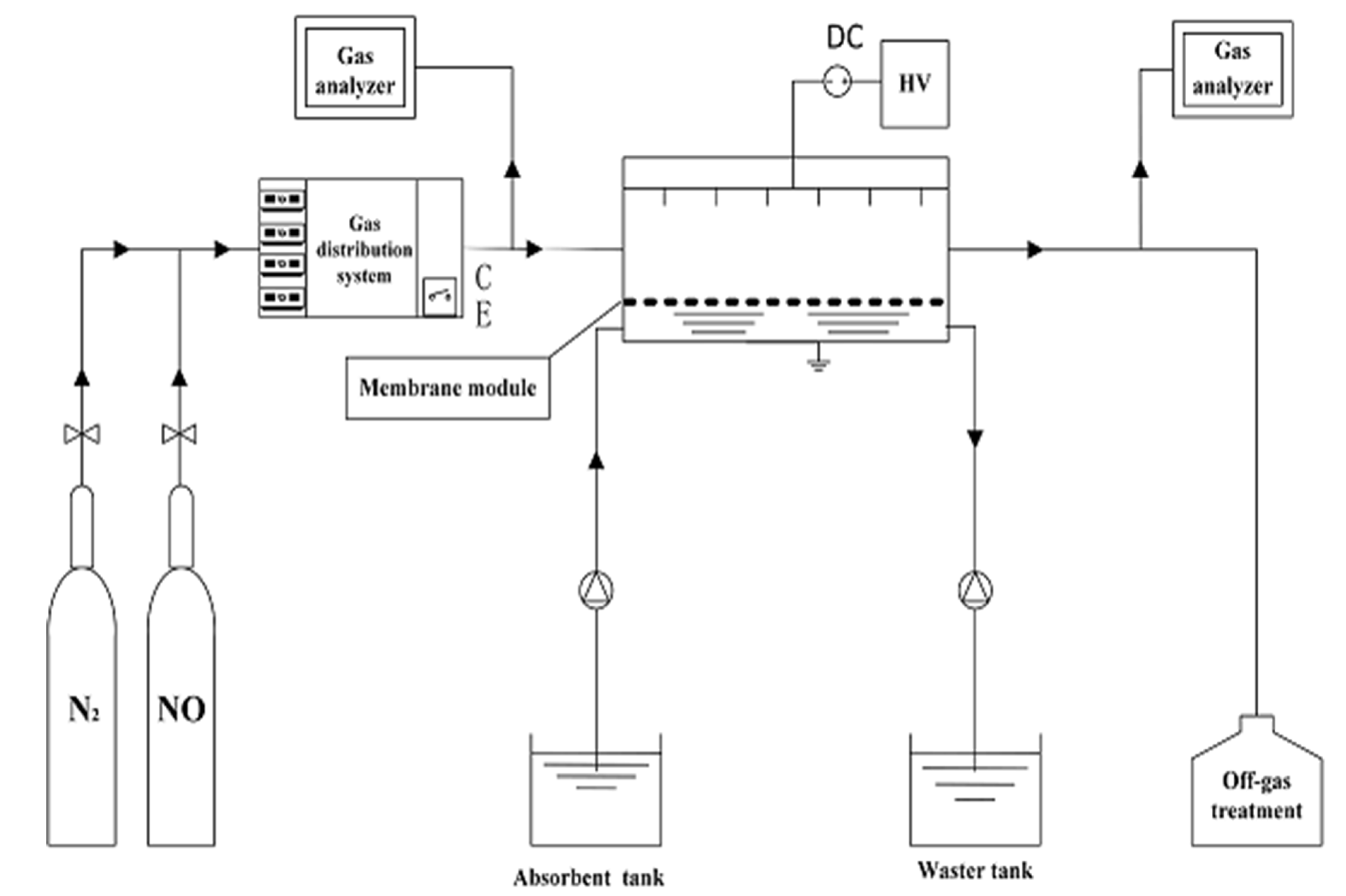
Figure 1. The schematic diagram of the integrated electromigration membrane reactor for NO separation.
Applsci 10 05071 g001
Figure 2. Effect of discharge voltage on separation efficiency.
Applsci 10 05071 g002
Figure 3. Effect of discharge voltage on total mass transfer coefficient.
Applsci 10 05071 g003
Figure 4. Effect of gas flow rate on separation efficiency.
Applsci 10 05071 g004
Figure 5. Effect of gas flow rate on total mass transfer coefficient.
Applsci 10 05071 g005
Figure 6. Effect of inlet concentration on separation efficiency.
Applsci 10 05071 g006
Figure 7. Effect of inlet concentration on total mass transfer coefficient.
Applsci 10 05071 g007
Figure 8. Effect of absorbents on separation efficiency.
Applsci 10 05071 g008
Figure 9. Effect of absorbents on total mass transfer coefficient.
Applsci 10 05071 g009