Review

Smart Power Electronics–Based Solutions to Interface Solar-Photovoltaics (PV), Smart Grid, and Electrified Transportation: State-of-the-Art and Future Prospects

by
Sandra Aragon-Aviles
*,
Ashutosh Trivedi
and
Sheldon S. Williamson
*
Department of Electrical, Computer and Software Engineering & Smart Transportation Electrification and Energy Research (STEER) Group, Ontario Tech University, Oshawa, ON L1G 0C5, Canada
*
Authors to whom correspondence should be addressed.
Appl. Sci. 2020, 10(14), 4988; https://doi.org/10.3390/app10144988
Submission received: 10 June 2020 / Revised: 14 July 2020 / Accepted: 17 July 2020 / Published: 20 July 2020

Abstract

:
The need to reduce the use of fossil fuels and greenhouse gas (GHG) emissions produced by the transport sector has generated a clear increasing trend in transportation electrification and the future of energy and mobility. This paper reviews the current research trends and future work for power electronics-based solutions that support the integration of photovoltaic (PV) energy sources and smart grid with charging systems for electric vehicles (EVs) and plug-in hybrid electric vehicles (PHEV). A compressive overview of isolated and non-isolated DC–DC converters and AC–DC converter topologies used to interface the PV-grid charging facilities is presented. Furthermore, this paper reviews the modes of operation of the system currently used. Finally, this paper explores the future roadmap of research for power electronics solutions related to photovoltaic (PV) systems, smart grid, and transportation electrification.

1. Introduction

There is growing concern in the world over climate change and global warming. Since one of the main causes of global warming is greenhouse gas (GHG) emissions, its reduction is an indisputable and urgent need. According to a report presented by the International Energy Agency (IEA), transportation and electricity/heat generation sectors represent more than 60% of the CO2 emissions as shown in Figure 1 [1,2]. Although the total energy spent in the transportation sector is used primarily by road, railway, ship, and aviation transport, road transport represents three quarters of the total [3]. The report also shows that, in 2017, worldwide CO2 emissions from fossil fuel combustion, such as coal and oil approached to 14.5 GT and 11.37 GT, respectively [2]. In more recent studies, it has been analyzed that even global consumption fossil fuel will be lower with high penetration of EV in transportation, but the efficacy in long-term GHG reduction will only be achieved when EV policy incorporates maximum uses of renewable energy with carbon pricing [4].
Both conventional electric power and conventional vehicles rely on the combustion of fossil fuels, which contributes to the emission of CO2 [5,6]. Therefore, the use of grid-connected renewable energy sources, electric vehicles (EVs), and plug-in hybrid electric vehicles (PHEVs) are a realistic solution that will reduce CO2 emissions and dependence on fossil-based sources, promising to be the future of energy and mobility [5,7]. This is where the smart grid plays an important role in the game, making processes more efficient, ensuring optimal system energy management, reducing costs, increasing reliability, and facilitating the integration of renewable energy sources such as photovoltaic solar energy, and electric transport [8,9,10].
Over the last 5–10 years, there has been significant advancement in technology in various fields, especially those that contribute to a smart grid infrastructure and real-time communication/pricing—smart meters, advanced information/communication technology, etc. [11]. If there were a method to organize and schedule EV charging efficiently without adding stress to the power distribution source, such a model would serve as a great standard for a new modern power system [11].
Currently, much of the control systems technology is not sophisticated enough to handle real-time-pricing scenarios; however, increasing world demand has allowed for technological advancements, but ultimately, introducing a deregulated power market would allow such advancements to occur rapidly. What would result would be a shift to a smart grid network from the existing grid system in place. The smart grid would allow enhancements to be made in the form of dynamic loads and a potential energy buffer to the EVs and dynamic loads [11].
The current trend of renewable energy sources dominating an ever-increasing share of the world’s power grid mix has being increasing steadily over the past year. According to a report presented by the International Renewable Energy Agency (IRENA, Abu Dhabi, UAE) [12], by the end of 2019, renewable capacity had increased by 176 gigawatts (GW), compared to the previous year, to a capacity of 2537 GW. In the same report, it was also stated that in the last 10 years, the global solar photovoltaic (PV) capacity has increased from 40.2 GW to 580.1 GW. There are several influences that have resulted in the continuous integration of solar PV into EV charging system—rapid growth in global demand for EVs, concerns over the effects of GHG, and a decrease in the price of solar PV modules [13].
In various studies, the EV market is expected to grow 800% by 2030 [14]. The main reason for the increasing popularity of EVs are their potential to reduce CO2 emissions and transportation costs, not to mention the ability of electric vehicles to serve as an independent distributed energy source [1,11]. The literature mentions various ancillary services that can be provided to the grid via an EV, such as frequency and voltage regulation, peak power shaving, and spinning reserve [1,5,11]. Because the number of EVs on the road is increasing over time, a new concept was created as a method for EVs to transfer their stored energy back to the grid—vehicle-to-grid (V2G) [1,11,15,16]. Currently, the infrastructure is not capable of this idea and thus an upgrade will be required [1].
Transportation electrification (TE) appears to be a promising solution to various global concerns—climate change, fuel economy, geopolitical, and energy security [5]. Its gaining popularity is tied to its ability to fix the aforementioned concerns. Some of the challenges that a smart grid faces are control, power quality, and reliability. A potent information and communication infrastructure alongside advance control schemes will be essential in the final establishment of TE [5]. Hence, it is necessary to explore and implement new innovative technologies to solve these challenges.
Smart grid/microgrid, photovoltaic, and electric vehicle technologies are advancing at a rapid rate. The foundation of these technologies is based on advancements in communication systems and power electronics (PE) converters. While PE converters allowing flexible control on electric power delivery systems, communication systems are improving reliability and robustness to these systems. In the last decade, various PE converters have been proposed, designed, and introduced in the industry. At the design and topological conception level, deriving application of PE-converters are trivial; hence, they are interchangeable and useful to more or less to all of these technologies. However, a small difference in their operational mechanism may make them slightly better for use in a particular technology and interface.
When choosing the right PE converter to interface PV, smart grid, and EVs/PHEVs, it is important to identify the main challenges that this interfacing systems has to overcome. According to the literature, the following are some of the main issues of interfacing these three systems [17,18,19]:
  • Excessive current harmonic distortion on the grid—when interfacing an EV battery to the grid, the battery is seen as a high-power DC load that continuously draw power from the grid, producing a high harmonic distortion;
  • Sophisticated tracking algorithms has to be used to optimize the extraction of the maximum power point (MPP) of the PV array at any extreme environment conditions;
  • It is important to follow the behavior of the PV module at higher frequencies, trying to avoid high voltage ripples at the output side of the DC–DC converter used at the PV stage. If there are high ripples, it will produce an instability in the MPP;
  • Depending on the requirements of the system, the type of galvanic isolation at the input or output of the system must be decided, considering decisive factors such as weight, cost, additional losses produced in the system, and the power factor;
  • Adequate DC output so it meets the power quality requirements of the AC grid;
  • When using non-isolated inverters, there are associated problems such as DC current injection to the grid and common mode leakage current.
This paper presents a comprehensive review of the current state and future trends on the DC–DC and AC–DC converter topologies used to interface EVs/PHEVs with smart grid and PV energy sources, considering the challenges mentioned above in order to choose the right topology. The paper is organized as follows. Section 2 presents a brief overview regarding EV charging standards and PV systems. Followed by Section 3, where is showed the typical system structure of a PV/grid-tied EV charging system and its modes of operation. Additionally, in Section 4, several isolated and non-isolated DC–DC converters and AC–DC converter topologies are described. Finally, Section 5 presents a summary of the main points of the paper and the possible future work that can be developed to improve the power electronics-based solutions to interface PV and smart grid with electric transportation.

2. Overview of EV and PV Systems

This section presents a detailed review of EV charger classification and standards. It also describes the different power architectures for integration of PV to the grid.

2.1. Electric Vehicles

According to the definition of Bhatti et al. [13], a vehicle that is powered by electrical means whilst using one or more motors for motion is called an EV. Although the classification of EVs encompass hybrid electric vehicles (HEV)s, battery electric vehicles (BEVs), PHEVs, and extended range electric vehicles (EREVs) [5,20,21], this paper is only focused on the BEVs and PHEVs. BEVs are equipped with a fully electric drivetrain, which is powered by rechargeable batteries. On the other hand, PHEVs have a hybrid vehicle drivetrain, which uses a combination of an internal combustion engine (ICE) and electrical power, similar to a HEV, although its rechargeable battery can be charged by plugging it into an external power supply, unlike HEVs [5,22].
EV chargers can be classified as on-board or off-board and conductive or inductive. Based on the place where the battery charger is installed, it can be classified as on-board or off-board. In this way, an on-board battery charger is installed inside the EV, while off-board chargers are placed outside the EV [23,24]. Battery chargers can also be classified as conductive or inductive, depending on the mode of power transfer from the power source to EV [23]. In this way, power flow between the PV/grid and the EV battery is delivered using plugs and sockets when utilizing conductive chargers [23,24]. On the other hand, the transfer of power using resonance via a wireless medium is allowed by the inductive chargers [24]. However, the inductive EV chargers are not considered in this paper.
Moreover, there are different standards available that regulate conductive charging operations for EVs/PHEVs with many classifications and rules regarding charging topologies, communication and connectors [25].
The Society of Automotive Engineers’ (SAE) SAE J1772 standard is one of the most accepted standards for EV/PHEV charging power converters [23,25]. As stated in the SAE J1772 standard, three AC charging power levels are designed for on-board chargers, whereas three DC charging power levels are dedicated for off-board chargers [22,23,24,25], as shown in Table 1.
The AC Level 1 charging is defined for slow charging operations. It is intended to be used for single-phase AC sources in common household circuits or charging stations with power levels that peak at 1.92 kW [22,25]. The AC charging level 2 and 3 refers to semi-fast charging and fast charging, respectively. However, this paper is only focused on DC charging systems.
The DC charging systems are installed at fixed locations and are built with dedicated wiring [22]. In addition, this charging systems are known as fast charging systems since they can handle higher power levels, charging the electric vehicles in less time compared with the level 1 AC chargers. Although each EV battery pack requires an specific power level supply, modern DC charging stations have implemented a system that identifies the voltage level of the battery pack and adjusts to that [22].
Depending on the flow of the power allowed by the charger, two types of charging systems can be found—unidirectional or bidirectional [27]. When the power only flows in one direction from the grid/PV into the battery, it is called unidirectional. On the other hand, when the power also flows from the battery to the grid, it is called bidirectional, under the concept of V2G, as mentioned in Section 1 [15,27].

2.2. PV Systems

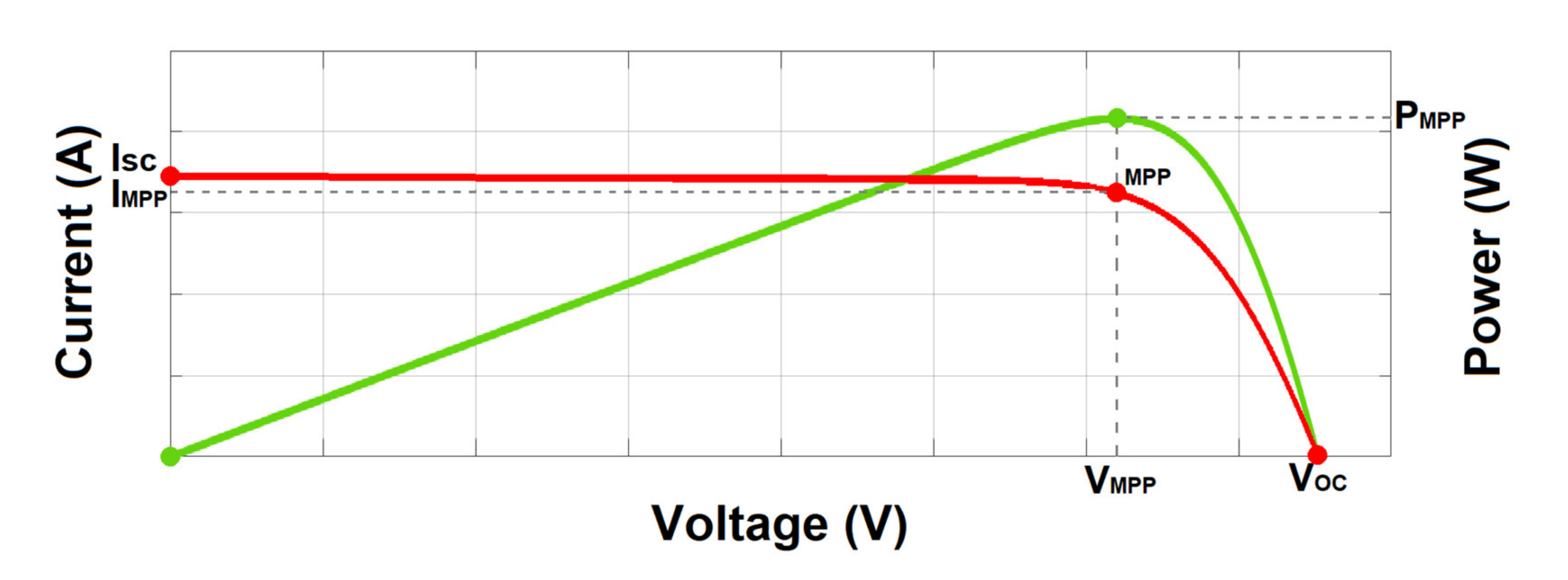
When studying how to integrate PV systems into the grid, first, it is very important to understand how a PV panel work. Figure 2 shows the current-voltage (I-V) and power-voltage (P-V) characteristic curves of a PV module. There are two important parameters of a PV module—short-circuit current (ISC), which is the current that flows through the solar cells when its voltage is zero; and open-circuit voltage (VOC), which is the maximum voltage a solar cell can provide when the current is zero. The power drawn from a solar module is a product of the PV module voltage and current setpoints. As can be seen in Figure 2, the power-voltage (P-V) characteristic curve of a PV module has a single maximum power point (MPP) corresponding to a specific current (IMPP) and voltage (VMPP) under a level of constant irradiance [28]. Then, one of the main purposes of a DC–DC converter used on a PV system is to achieve the MPP of the PV array.
It is also important to understand the different categories of structures generally used to connect the PV source to the load. These types of structures are known as centralized, string structure, and module architectures.
The centralized structure aims at connecting all the PV modules of a PV array to a single converter, which, depending on the system needs, can be a DC–DC converter or a DC–AC inverter, as shown in Figure 3a. The main advantages of using this structure are the low-cost installations and the simplicity of control as discussed in the literature [30]. However, the main drawback of this structure is the high variation of the output power due to the mismatch conditions of the series-connected PV modules. Mismatch conditions are generally caused by partial shading or dust accumulation in the PV modules or, in other cases, due to silicon impurities or aging of the solar panels. Therefore, when these mismatch conditions arise, a decrease in system efficiency is expected since the system cannot extract the maximum power from the PV array [28]. Some of the most used inverter topologies when using this type of structure are low-frequency transformers and three-phase full bridges using insulated-gate bipolar transistors (IGBTs) [19].
On the other hand, string and module structures for PV systems were designed and developed to extract the maximum energy from the system [28,31].
Figure 3b shows the string system architecture. As can be seen from the figure, PV modules are series-connected and grouped in different strings. Unlike the centralized structure, each PV string has its own DC–DC converter or AC–DC inverter that uses a maximum power point tracking (MPPT) controller to extract the MPP of each string. This type of structure aims to increase the efficiency of the system when mismatch conditions appear compared to the centralized structure, although the power losses remain significant within the same strings [28]. To further improve the MPP tracking efficiency of the solar PV system under mismatched conditions, the use of integrated module inverter structures has been proposed in the literature. In this structure, each PV module has its own power converter with an MPPT controller, as shown in Figure 3c. The main benefit of using this structure is the improvement on the MPP tracking efficiency for each PV module, thus decreasing the power losses produced by mismatch conditions. However, the use of this type of structure increases costs since a power converter is required for each photovoltaic module used [31,32].
As described in the literature, in order to achieve high DC bus voltages in PV–grid tied systems, a PV module series connection is usually used, allowing it to supply power to both the AC grid and battery storage devices at a high efficiency (in this case, to the EV battery charger) [28,33]. However, as discussed above, one of the main challenges to solve on the PV stage is the mismatch conditions that affect the power provided by the PV array.

3. PV-Grid Tied Charging Stations for EVs and PHEVs

In this section it is presented the typical structure for a PV/grid-tied EV charging system. The most important features and characteristics that the power electronic converters must provide are addressed. Additionally, the operation modes of the system are explained.

3.1. Structure of the System

The typical structure for a PV/grid-tied charging system for EV/PHEV is shown in Figure 4. The structure is interfaced through three power converters; in the PV stage, there is a DC–DC converter with maximum power point tracking (MPPT), which is used to step up the voltage supplied by the PV array and at the same time provide the maximum power to the common DC bus; a bidirectional AC–DC inverter, which is part of the AC grid stage, aims to control the power factor and the current injected into the grid, and regulate the DC voltage to adapt to that required by the common DC bus [34]; and a bidirectional DC–DC converter, which belongs to the charger stage, serves as an interface for the EV/PHEV, controlling the DC charging current. All of these components are connected to the common DC bus, which has a voltage range from 200 VDC to 600 VDC, according to the SAE J1772 standard reviewed on Section 2.1 [13]. A central controller is also required in the system to establish the power flow and activation of the power converters based on different constraints, e.g., minimum charging cost, maximum profit, etc. [13,35,36,37].
The use of a bidirectional inverter in the AC grid stage, as shown in Figure 4, will allow the transfer of excess power from the PV array to the AC grid throughout the sunny hours of the day. Additional, with this proposed system, the flow of power from the EV battery to the grid (V2G) will be allowed. During low solar irradiation, the battery can draw energy from the grid. In order to facilitate the inverter and rectification modes of operation in the PV/grid-tied charging system, a bidirectional inverter is used [38,39,40,41].
To interconnect all the stages, the power converters must guarantee some characteristics to suit the system. For example, according to the grid needs, the power converters must provide a high power factor, with zero distortion and galvanic isolation to protect both, the grid and the EV [17]. As stated in the literature, this galvanic isolation can be implemented on the front-end of the AC–DC inverter through a low-frequency transformer. Another option to implement the isolation can be using an isolated DC–DC power converter at the charger stage by using a high frequency transformer [17,34].
Furthermore, at the charging stage, a power converter is required to control the charging power of the EV battery, so that the battery life can be maximized. It is also worth noting that the converters selected for this application must have high efficiency since high power is transferred to and from the common DC bus. [17].

3.2. Operating Modes

To operate the proposed system shown in Figure 4, a central controller connected to the three power electronic converters in the system is required. This central controller aims to manage the battery charging operation, depending on the state of charge (SOC), controlling the power flow in the system. Based on the state of the EV battery, the power available to be delivered by the PV array and the grid electricity prices, the central controller will decide the mode of operation of the system. The following are the typical modes of operation of a PV/grid-tied EV charging system [13]:

3.2.1. Mode 1 (PV to Battery)

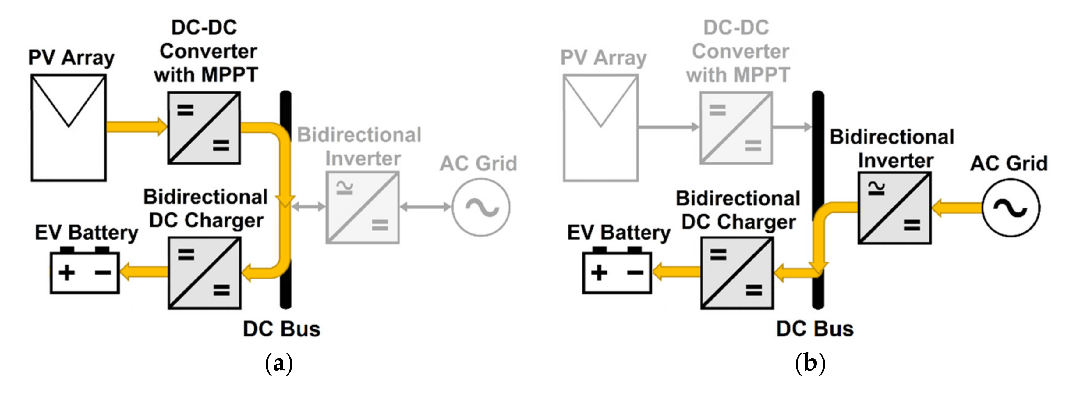
This operating mode works when the PV array provides enough energy to completely charge the EV. In this way, the MPP is obtained through the DC–DC converter on the PV stage, and it is transferred to the battery by the DC–DC converter of the DC charger stage. The main purpose of this converter is to regulate the voltage from the common DC bus to suit the charging parameters of the EV battery pack. When operating in this mode, the grid is electrically disconnected from the EV charging system. The charging by PV only mode is shown in Figure 5a.

3.2.2. Mode 2 (Grid to Battery)

In this operation mode, the EV will be charged directly with the power from the AC grid only if the PV array cannot supply the power necessary to feed the battery pack of the EV. In this case, the irradiance must be extremely low or non-existent, thus cutting off the supply of power to the EV. In this way, the bidirectional inverter works as a rectifier, converting the AC power to DC directly to the common DC bus; then, this voltage is adjusted by the DC–DC charger to supply the required voltage for the EV. This mode of operation is shown in Figure 5b.

3.2.3. Mode 3 (PV and Grid to Battery)

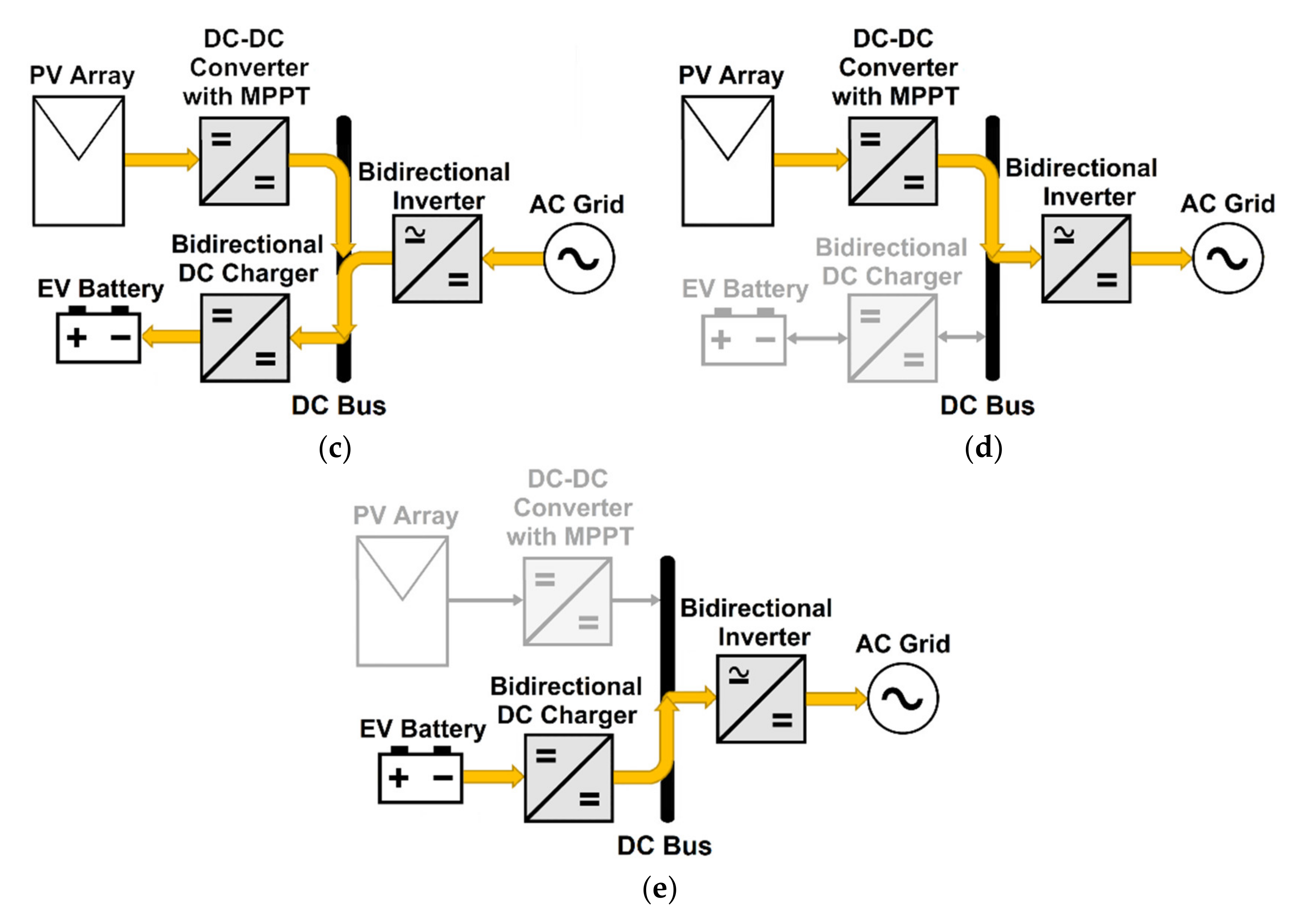
As shown in Figure 5c, in this operating mode the power required to charge the EV is provided by the grid and the PV at the same time. This mode comes into operation when the PV cannot provide enough power to independently charge the EV battery but is able to supply a certain part of the required power. Depending on how much energy the PV can distribute, the amount of energy supplied from the grid varies; any deficiency is reimbursed by the grid. As the nature of irradiance conditions is variable, the system controller has to properly distribute the amount of power delivered by the PV and the grid, ensuring that the power required by the EV is reached.

3.2.4. Mode 4 (PV to Grid)

During a scenario in which the PV is generating energy yet no EV is available for charging, a two-step conversion process is utilized to ensure excess energy is sold back to the grid, i.e., by the bidirectional inverter in inversion mode and MPPT DC-DC converter. Despite the EVs availability for charging, in certain circumstances, it would be more cost-efficient to engage in this practice. Amid an instance when the feed-in-tariff rate quite exceeds that which made such proposition viable, this circumstance would be much more feasible. This operating mode is displayed in Figure 5d.

3.2.5. Mode 5 (Vehicle-to-Grid)

A vehicle-to-grid (V2G) is used to transfer power in this approach as indicated in Figure 5e. At specific intervals of hours of the day, the cost of energy is the highest; ultimately, energy can be diverted from the EV to the grid when excess energy is present in the parking lot. This is easily attainable by utilizing the bidirectional DC–DC charger and the inverter. The negative side effect of this election is the reducing of the battery’s life that in this process is not chosen unless financial gains are made aware by choosing it.

4. Power Converter Topologies

This section presents several topologies of isolated/non-isolated DC–DC converters and AC–DC inverters to interface the PV, the grid, and the EVs/PHEVs, all of them classified depending on the stage where they can be used—the PV stage, AC grid stage, or charger stage for the EV. Several DC–DC and AC–DC converter topologies and their applications are discussed in references [13,17,22,25,29,33,34,38,42,43,44,45,46,47,48,49,50,51,52,53,54,55,56,57,58].

4.1. PV Stage (Unidirectional DC–DC Converters)

In the PV stage, a unidirectional DC–DC converter is required that is capable of extracting the maximum power from each solar module in a PV array and at the same time maintaining the voltage at the output of the converter, which is connected to the DC bus of the system.
During high temperatures and low levels of irradiation, the PV endures its main issues with performance, significantly reducing the power provided by the PV array [33]. When using non-isolated or transformerless converters, the use of series-connected PV modules is necessary to achieve the required voltage of the DC bus. However, as discussed in Section 2.2, these mismatch conditions become more problematic when series-connected PV modules are used. Many solutions are reported in the literature with the aim of addressing this problem.
As reported by Esram and Chapman [30], several maximum power point tracking (MPPT) techniques have been developed and implemented. The methods most used are perturb and observe, incremental conductance, fuzzy logic control, and hill climbing; however, this last technique is the most preferred, since it reduces oscillation in steady state, thus providing better tracking efficiency. On the other hand, methods such as artificial neural network or fuzzy logic control are more flexible when handling module mismatch or partial shading conditions according to [13,59].
The most used power converters for the PV stage are the standard non-isolated, boost, and buck-boost topologies. Although, there is also reported the use of Cuk and single-ended primary inductor converter (SEPIC) in the literature [13,29,42].
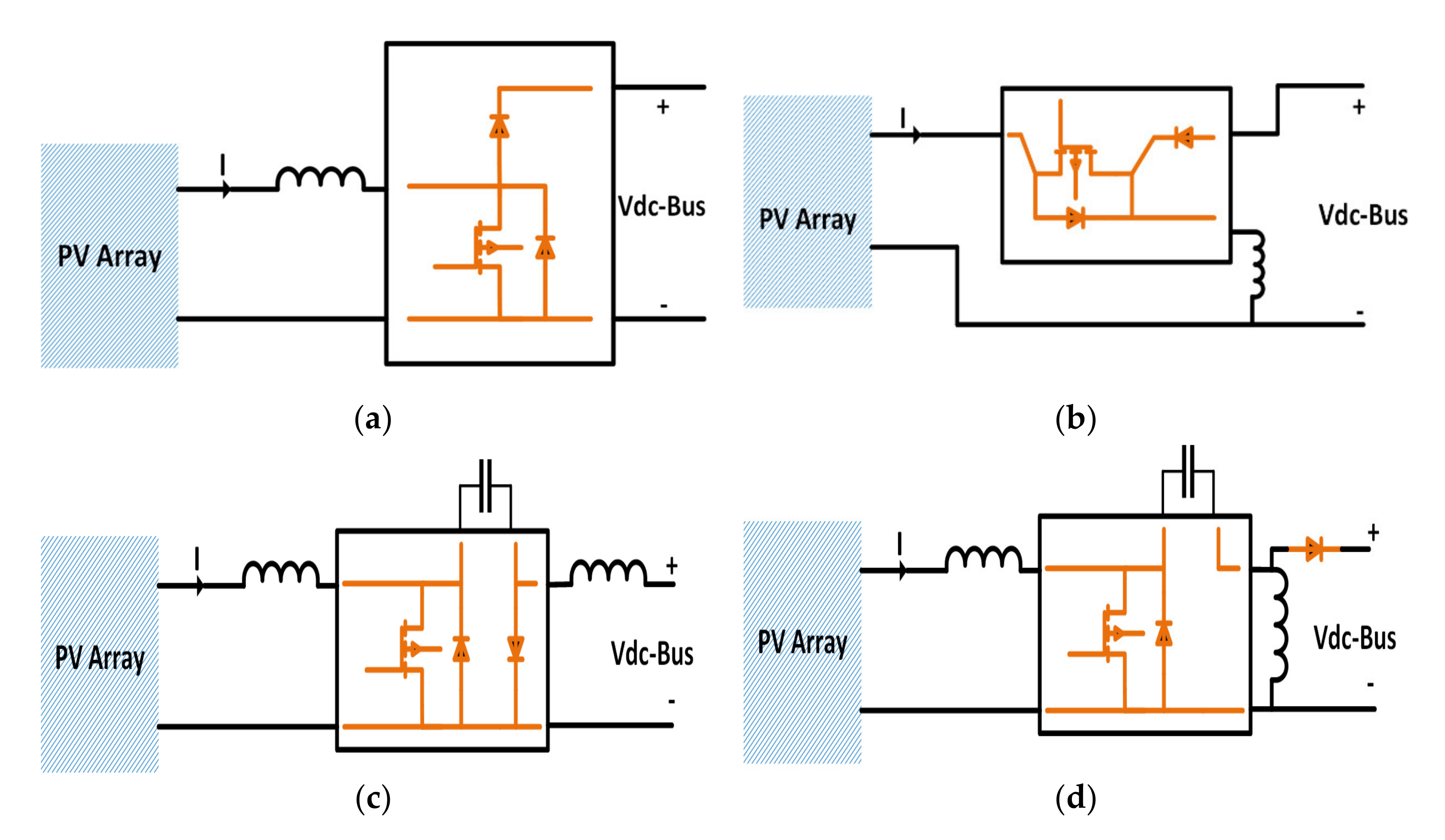
To acquire a higher output voltage, the input voltage magnitude must be stepped up accordingly as shown in Figure 6a by the DC–DC boost converter [29]. On the other hand, the magnitude of the input voltage can either be lower or higher than the output voltage magnitude when we speak of the buck-boost topology, as indicated in Figure 6b. This converter is developed using a boost and buck basic topologies cascade connected. The Cuk converter is shown in Figure 6c; its work mimics the buck-boost converter. The common terminal of the input voltage is employed with reverse polarity so that the Cuk converter can step up or down input voltage. The SEPIC shown in Figure 6d, also has the same features of a buck-boost converter: possesses a non-inverting output polarity and step up and down the input voltage [29].
Table 2 describes the main advantages, disadvantages, and applications of the aforementioned converters used in the PV stage.

4.2. AC Grid Stage (AC–DC Converters)

PV-grid connected charging systems for EV/PHEV can be connected either to a low voltage (LV) or a medium voltage (MV) AC grid [25]. However, this paper is focused on the LV AC source. In PV/grid-tied EV charging systems, unidirectional or bidirectional inverters can be used, though, bidirectional inverters are often used to enable the V2G mode of operation or to feed the excess power from the PV to the grid, as will be explained later in another section. Inversion and rectification are the two modes of operation of a bidirectional inverter. When operating in the inversion mode, the power on the DC bus is fed back to the grid, synchronizing the magnitude and frequency with that of the AC grid, acting as a DC-AC inverter. In contrast, when operating as a rectifier, power is transferred from the grid to the DC bus, configured as an AC-DC converter. Therefore, the inverter used in this stage must be able to operate in any of the current/voltage quadrants [13,16,54].
The following are the bidirectional AC-DC inverter topologies that will be discussed:
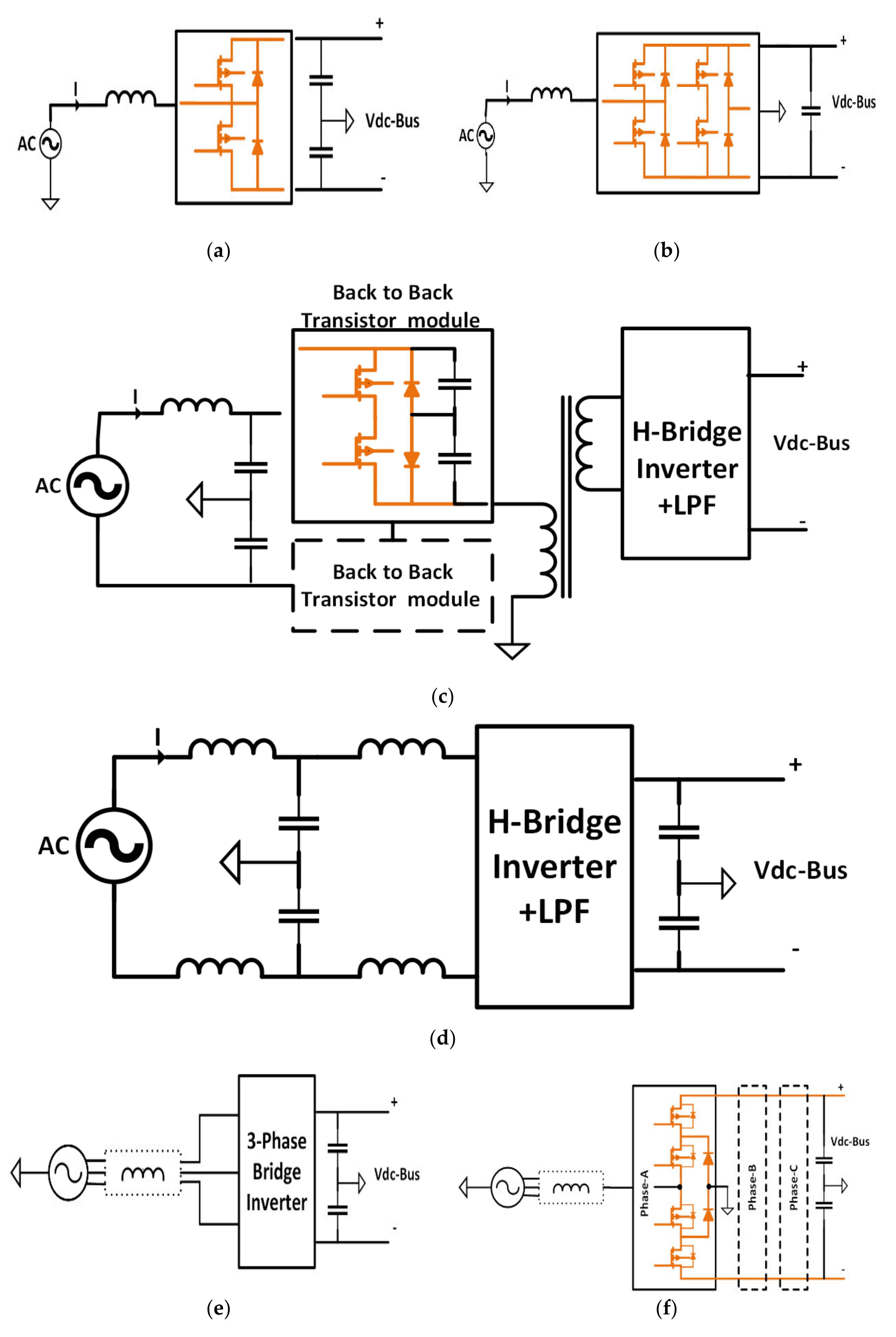
  • One-phase half-bridge (HB) bidirectional boost inverter (Figure 7a);
  • One-phase voltage source inverter (VSI) full-bridge (FB) bidirectional boost inverter (Figure 7b);
  • One-phase one-stage isolated bidirectional inverter with output low pass filter (LPF) (Figure 7c);
  • Full-bridge (FB) bidirectional inverter with leakage current reduction (Figure 7d);
  • Three-phase full-bridge (FB) bidirectional inverter (Figure 7e);
  • Three-level three-phase diode neutral point clamped (NPC) inverter (Figure 7f);
  • Three-phase bridgeless boost inverter (Figure 7g);
  • Three-phase Vienna rectifier (Figure 7h).
Table 3 presents a comparison of the main characteristics of the aforementioned bidirectional AC–DC converters topologies used in the rectifier/inverter stage on a PV/grid-tied EV charging system.

4.3. Charger Stage (Bidirectional DC–DC Converters)

The main purpose of a DC–DC converter is to regulate the output voltage and current on the common DC bus to suit the current required to charge the EV [13]. This paper is focused on bidirectional topologies; however, if the V2G operation is not required, this capability is not necessary [13]. Several topologies are discussed on the literature [13,22,34,38]. These topologies are classified into isolated and non-isolated DC–DC converters. However, isolated converters are more preferred than non-isolated types because of the high gain and galvanic isolation [13].

4.3.1. Non-Isolated Charger Topologies

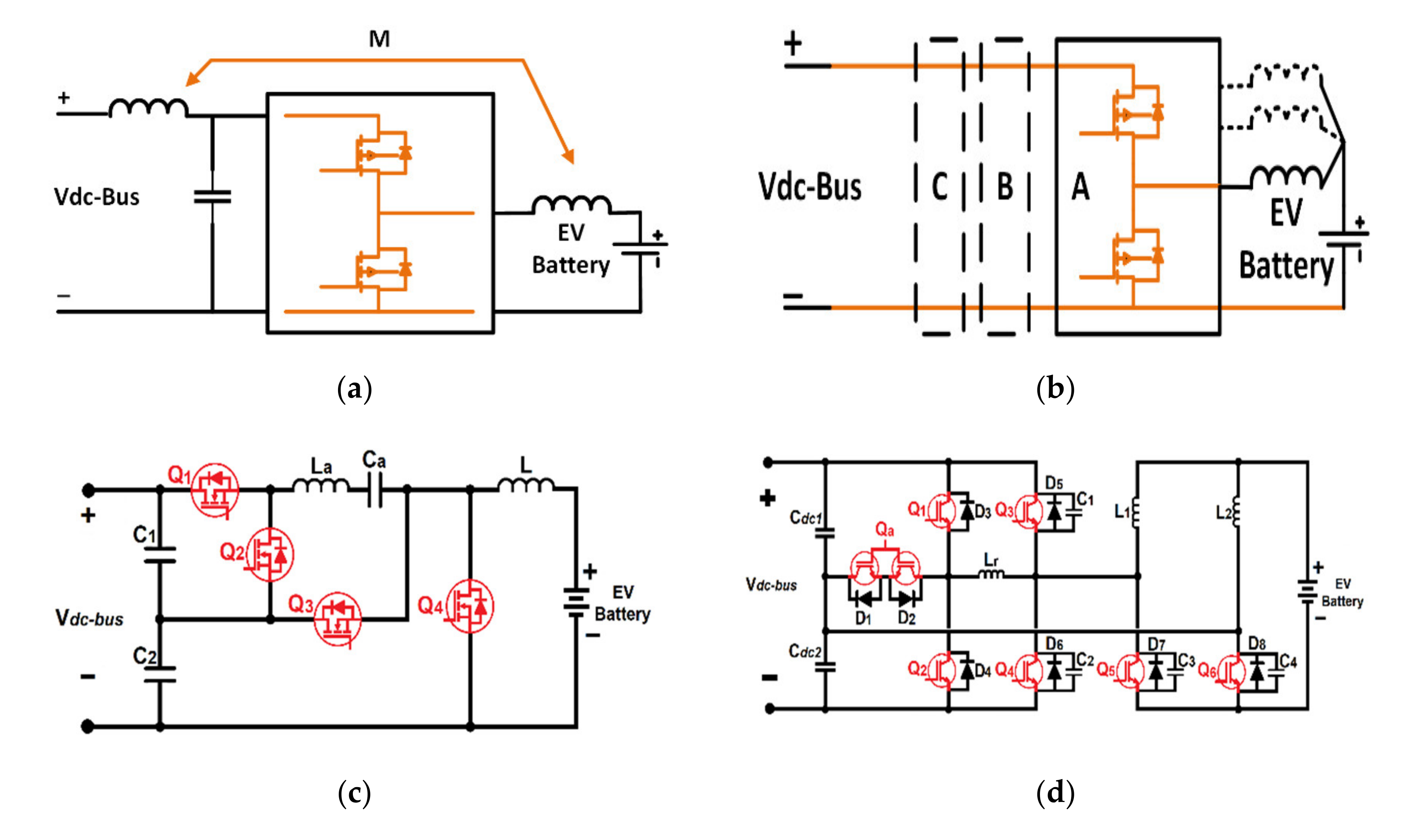
The following are the non-isolated bidirectional converter topologies that will be analyzed:
  • Bidirectional converter with coupled inductors and output filter (Figure 8a);
  • Zero-voltage-switching (ZVS) interleaved HB converter (Figure 8b);
  • HB converter with resonant circuit (Figure 8c);
  • Zero-voltage-transition (ZVT) interleaved converter with resonant circuit (Figure 8d);
  • ZVS HB converter with coupled inductors (Figure 8e);
  • Three-phase interleaved buck converter (Figure 8f).
Table 4 presents a comparison of the main characteristics of the aforementioned non-isolated bidirectional DC–DC converters used in the EV charger stage.

4.3.2. Isolated Charger Topologies

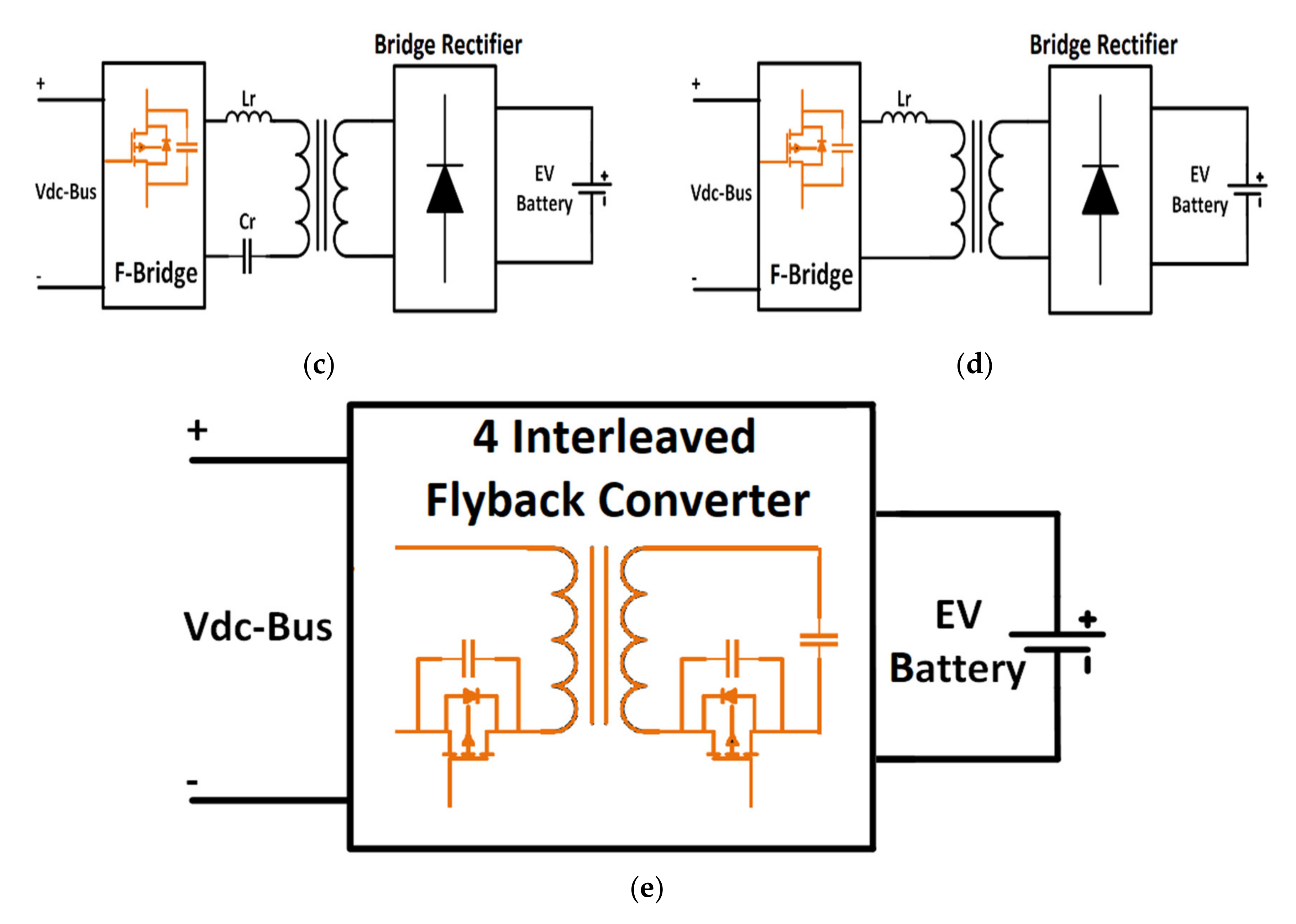
The following are the isolated bidirectional DC-DC converter topologies that will be discussed:
  • ZVS dual active bridge (DAB) converter (Figure 9a);
  • Phase-shift FB converter (Figure 9b);
  • FB LLC resonant converter (Figure 9c);
  • ZVS FB converter with capacitive output filter (Figure 9d);
  • Four interleaved flyback converters (Figure 9e).
Table 5 describes a comparison of the main characteristics of the above-mentioned isolated bidirectional DC–DC converters used in the EV charger stage.

4.3.3. Single-Stage Conversion (Z-Source Inverter)

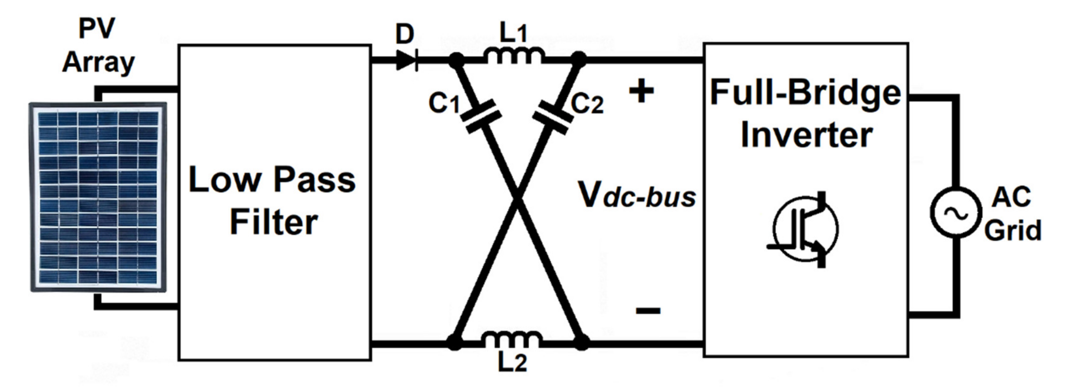
A single-phase Z-source inverter has been discussed in the literature [52,53,55]. The schematic of the Z-Source inverter is shown in Figure 10. One of the main advantages of the Z-converter is the double modulation capability, in addition to the fact that, while regulating the charge of the EV battery, it can simultaneously shape the grid current [53].
A single-phase modified Z-source inverter (ZSI) topology was proposed by Singh [55]. According to Singh in his proposed topology, the capacitor voltages vary between twice the minimum battery voltage up to twice the fully charged battery voltage when battery voltages vary between 200–500 V. The converter operates between D0min to Dmax for vpvmax to vpvmin respectively. The proposed cascaded configuration system has the following advantages [55]:
  • Single point of fault is avoided;
  • ZSI has a packed structure due to the decreased number of stages;
  • Galvanic isolation is feasible between the charger side and the PV and grid;
  • Presents an opening to step up the charging power levels by adding such converters;
  • Any battery voltage levels can be charged by changing the charger side of the converter between voltage sharing or current sharing;
  • Due to the dependency on the size of passive components, higher frequency this inverter can be designed using wide-band-gap devices.

5. Conclusions and Future Prospects

This paper thoroughly presented an intensive review on the most used power electronics interfaces for PV, smart grid, and transportation electrification. Several topologies of isolated and non-isolated DC–DC converters were described. The main advantages and disadvantages of the unidirectional DC–DC converter topologies used to interface PV modules with the grid and EV chargers were described. From the literature, it was concluded that the most used topologies for PV/grid-tied systems are the boost and buck-boost converters, although other topologies such as SEPIC and Cuk converters are also being improved to obtain a higher efficiency at a cheaper cost.
Additionally, it is known that the MPPT is a very important part of the PV controller; for this reason, there are many studies on the improvement of the MPPT techniques to enhance the efficiency of the PV system. A complete summary of numerous isolated and non-isolated AC–DC inverters were described. It has been observed that the non-isolated AC–DC inverters can only be used with systems that include an isolated front low frequency transformer. Otherwise, there has to be implemented an isolated power converter solution to interface the grid with the common DC bus.
The cost in most of the converter topologies is compromised by the efficiency, since, in order to obtain a higher efficiency in many cases, it has been necessary to increase the number of components of the system. Thus, the reduction of the component cost is one of the targets for the future work on the power electronics-based solution interfaces for PV/grid-tied charging systems. Less expensive solutions in which the system stages are reduced, therefore reducing the number of components, such as the modified single-stage Z-source converter, are currently being studied. It is necessary to keep researching on cost-effective solutions to interface EV chargers to different supply sources.

Author Contributions

Conceptualization, S.S.W.; reviewed and wrote the first version of the manuscript, S.A.-A.; reviewed and edited final draft, S.A.-A., A.T., and S.S.W.; supervision, S.S.W. and A.T.; funding acquisition, S.S.W. All authors have read and agreed to the published version of the manuscript.

Funding

This research was funded by the Canada Research Chairs (CRC) Program and the Natural Sciences and Engineering Research Council of Canada (NSERC).

Acknowledgments

The authors would like to acknowledge the technical guidance and support from all past and current research personnel at the Ontario Tech University—Smart Transportation Electrification and Energy Research (STEER) group, especially, Florence Berthold, Siddhartha Anirban Singh, Giampaolo Carli, and Arash Shafiei.

Conflicts of Interest

The authors declare no conflict of interest.

References

  1. Zidan, A.; Gabbar, H.A. Design and Control of V2G. In Smart Energy Grid Engineering; Elsevier: Amsterdam, The Netherlands, 2017; pp. 187–205. [Google Scholar]
  2. IEA. CO2 Emissions from Fuel Combustion 2019—Highlights; Highlights 2019 edition; International Energy Agency (IEA): Paris, France, 2019; p. 165. [Google Scholar]
  3. Singh, K.V.; Bansal, H.O.; Singh, D. A Comprehensive Review on Hybrid Electric Vehicles: Architectures and Components. J. Mod. Transp. 2019, 27, 77–107. [Google Scholar] [CrossRef] [Green Version]
  4. Zhang, R.; Fujimori, S. The Role of Transport Electrification in Global Climate Change Mitigation Scenarios. Environ. Res. Lett. 2020, 15, 034019. [Google Scholar] [CrossRef]
  5. Shaukat, N.; Khan, B.; Ali, S.M.; Mehmood, C.A.; Khan, J.; Farid, U.; Majid, M.; Anwar, S.M.; Jawad, M.; Ullah, Z. A Survey on Electric Vehicle Transportation within Smart Grid System. Renew. Sustain. Energy Rev. 2018, 81, 1329–1349. [Google Scholar] [CrossRef]
  6. Badin, F.; Scordia, J.; Trigui, R.; Vinot, E.; Jeanneret, B. Hybrid Electric Vehicles Energy Consumption Decrease According to Drive Train Architecture, Energy Management and Vehicle Use. In IET Hybrid Vehicle; IET Digital Library: Coventry, UK, 2006; Volume 11, pp. 213–223. [Google Scholar] [CrossRef]
  7. Narayan, A. The Electrification of Transport Could Transform our Future—If We are Prepared for It. Available online: https://www.weforum.org/agenda/2018/08/we-must-get-it-right-with-electric-vehicles-for-the-sake-of-our-planet/ (accessed on 6 May 2020).
  8. Gabbar, H.A. Smart Energy Grid Engineering; Elsevier: Amsterdam, The Netherlands, 2017. [Google Scholar] [CrossRef]
  9. Su, W.; Eichi, H.; Zeng, W.; Chow, M.-Y. A Survey on the Electrification of Transportation in a Smart Grid Environment. IEEE Trans. Ind. Inform. 2012, 8, 1–10. [Google Scholar] [CrossRef]
  10. Cheng, X.; Hu, X.; Yang, L.; Husain, I.; Inoue, K.; Krein, P.; Lefevre, R.; Li, Y.; Nishi, H.; Taiber, J.G.; et al. Electrified Vehicles and the Smart Grid: The ITS Perspective. IEEE Trans. Intell. Transp. Syst. 2014, 15, 1388–1404. [Google Scholar] [CrossRef]
  11. Mwasilu, F.; Justo, J.J.; Kim, E.-K.; Do, T.D.; Jung, J.-W. Electric Vehicles and Smart Grid Interaction: A Review on Vehicle to Grid and Renewable Energy Sources Integration. Renew. Sustain. Energy Rev. 2014, 34, 501–516. [Google Scholar] [CrossRef]
  12. IRENA. Renewable Capacity Statistics 2020; International Renewable Energy Agency (IRENA): Abu Dhabi, UAE, 2020. [Google Scholar]
  13. Bhatti, A.R.; Salam, Z.; Aziz, M.J.B.A.; Yee, K.P.; Ashique, R.H. Electric Vehicles Charging Using Photovoltaic: Status and Technological Review. Renew. Sustain. Energy Rev. 2016, 54, 34–47. [Google Scholar] [CrossRef]
  14. MarketsAndMarkets. Electric Vehicle Market by Vehicle (Passenger Cars & Commercial Vehicles), Vehicle Class (Mid-Priced & Luxury), Propulsion (BEV, PHEV & FCEV), EV Sales (OEMs/Models) Charging Station (Normal & Super) & Region—Global Forecast to 2030. 2019. Available online: https://www.marketsandmarkets.com/Market-Reports/electric-vehicle-market-209371461.html (accessed on 19 July 2020).
  15. Berthold, F. Integration of Plug-In Hybrid Electric Vehicle with the Grid Using Vehicle-to-Home and Home-to-Vehicle Capabilities. Ph.D. Thesis, Concordia University, Montréal, QC, Canada, 2014. [Google Scholar]
  16. Fathabadi, H. Novel Solar Powered Electric Vehicle Charging Station with the Capability of Vehicle-to-Grid. Sol. Energy 2017, 142, 136–143. [Google Scholar] [CrossRef]
  17. Dusmez, S.; Cook, A.; Khaligh, A. Comprehensive Analysis of High Quality Power Converters for Level 3 Off-Board Chargers. In Proceedings of the 2011 IEEE Vehicle Power and Propulsion Conference, Chicago, IL, USA, 5–8 September 2011; pp. 1–10. [Google Scholar] [CrossRef]
  18. Kumar, A.; Sensarma, P. A Four-Switch Single-Stage Single-Phase Buck–Boost Inverter. IEEE Trans. Power Electron. 2017, 32, 5282–5292. [Google Scholar] [CrossRef]
  19. Schimpf, F.; Norum, L.E. Grid Connected Converters for Photovoltaic, State of the Art, Ideas for Improvement of Transformerless Inverters. In Proceedings of the Nordic Workshop on Power and Industrial Electronics (NORPIE/2008), Espoo, Finland, 9–11 June 2008. [Google Scholar]
  20. Popović-Gerber, J.; Oliver, J.A.; Cordero, N.; Harder, T.; Cobos, J.A.; Hayes, M.; O’Mathuna, S.C.; Prem, E. Power Electronics Enabling Efficient Energy Usage: Energy Savings Potential and Technological Challenges. IEEE Trans. Power Electron. 2012, 27, 2338–2353. [Google Scholar] [CrossRef]
  21. Preetham, G.; Shireen, W. PV Integrated Smart Charging of PHEVs Based on DC Link Voltage Sensing. IEEE Trans. Smart Grid 2014, 5, 1421–1428. [Google Scholar] [CrossRef]
  22. Williamson, S.S.; Rathore, A.K.; Musavi, F. Industrial Electronics for Electric Transportation: Current State-of-the-Art and Future Challenges. IEEE Trans. Ind. Electron. 2015, 62, 3021–3032. [Google Scholar] [CrossRef]
  23. Chau, K.T. Pure Electric Vehicles. In Alternative Fuels and Advanced Vehicle Technologies for Improved Environmental Performance; Woodhead: Cambridge, UK, 2014; pp. 655–684. [Google Scholar]
  24. Sharma, A.; Sharma, S. Review of Power Electronics in Vehicle-to-Grid Systems. J. Energy Storage 2019, 21, 337–361. [Google Scholar] [CrossRef]
  25. Rubino, L.; Capasso, C.; Veneri, O. Review on Plug-in Electric Vehicle Charging Architectures Integrated with Distributed Energy Sources for Sustainable Mobility. Appl. Energy 2017, 207, 438–464. [Google Scholar] [CrossRef]
  26. SAE International. Surface Vehicle Recommended Practice J1772, SAE Electric Vehicle and Plug in Hybrid Electric Vehicle Conductive Charge Coupler; SAE International: Warrendale, PA, USA, 2010. [Google Scholar]
  27. Lunz, B.; Sauer, D.U. Electric Road Vehicle Battery Charging Systems and Infrastructure. In Advances in Battery Technologies for Electric Vehicles; Elsevier: Amsterdam, The Netherlands, 2015; pp. 445–467. [Google Scholar] [CrossRef]
  28. Badawy, M.O. Grid Tied PV/Battery System Architecture and Power Management for Fast Electric Vehicle Charging. Ph.D. Thesis, University of Akron, Akron, OH, USA, 2016. [Google Scholar]
  29. Taghvaee, M.H.; Radzi, M.A.M.; Moosavain, S.M.; Hizam, H.; Hamiruce Marhaban, M. A Current and Future Study on Non-Isolated DC–DC Converters for Photovoltaic Applications. Renew. Sustain. Energy Rev. 2013, 17, 216–227. [Google Scholar] [CrossRef]
  30. Esram, T.; Chapman, P.L. Comparison of Photovoltaic Array Maximum Power Point Tracking Techniques. IEEE Trans. Energy Convers. 2007, 22, 439–449. [Google Scholar] [CrossRef] [Green Version]
  31. Pathipati, V.K.; Shafiei, A.; Carli, G.; Williamson, S.S. Integration of Renewable Energy Sources into the Transportation and Electricity Sectors. In Technologies and Applications for Smart Charging of Electric and Plug-in Hybrid Vehicles; Veneri, O., Ed.; Springer International Publishing: Cham, Switzerland, 2017; pp. 65–110. [Google Scholar] [CrossRef]
  32. Jiang, Y. Power Electronics Architectures and Controls for Photovoltaic Solar Energy Systems. Ph.D. Thesis, University of Alabama, Tuscaloosa, AL, USA, 2013. [Google Scholar]
  33. Dutta, S.; Chatterjee, K. A Buck and Boost Based Grid Connected PV Inverter Maximizing Power Yield from Two PV Arrays in Mismatched Environmental Conditions. IEEE Trans. Ind. Electron. 2018, 65, 5561–5571. [Google Scholar] [CrossRef]
  34. Chakraborty, S.; Vu, H.-N.; Hasan, M.M.; Tran, D.-D.; Baghdadi, M.E.; Hegazy, O. DC-DC Converter Topologies for Electric Vehicles, Plug-in Hybrid Electric Vehicles and Fast Charging Stations: State of the Art and Future Trends. Energies 2019, 12, 1569. [Google Scholar] [CrossRef] [Green Version]
  35. Ma, C.-T. System Planning of Grid-Connected Electric Vehicle Charging Stations and Key Technologies: A Review. Energies 2019, 12, 4201. [Google Scholar] [CrossRef] [Green Version]
  36. Meintz, A.; Markel, T.; Jun, M.; Zhang, J. Integrating PEVs with Renewables and the Grid; National Renewable Energy Lab. (NREL): Golden, CO, USA, 2016.
  37. Kisacikoglu, M. EV-Grid Integration (EVGI) Control and System Implementation; National Renewable Energy Lab. (NREL): Golden, CO, USA, 2016.
  38. Sujitha, N.; Krithiga, S. RES Based EV Battery Charging System: A Review. Renew. Sustain. Energy Rev. 2017, 75, 978–988. [Google Scholar] [CrossRef]
  39. Shafiei, A. Modeling, Analysis, and Design of a PV-Based Grid-Tied Plug-in Hybrid Electric Vehicle Battery Pack Charger. Master’s Thesis, Concordia University, Montréal, QC, Canada, 2013. [Google Scholar]
  40. Kamal, T.; Mumtaz, S.; Hassan, S.Z.; Khan, L. PV Based PHEVs Smart Charging Station Facility. In Proceedings of the 2015 Power Generation System and Renewable Energy Technologies (PGSRET), Islamabad, Pakistan, 10–11 June 2015; pp. 1–6. [Google Scholar] [CrossRef]
  41. Preetham, G.; Shireen, W. Photovoltaic Charging Station for Plug-In Hybrid Electric Vehicles in a Smart Grid Environment. In Proceedings of the 2012 IEEE PES Innovative Smart Grid Technologies (ISGT), Washington, DC, USA, 16–20 January 2012; pp. 1–8. [Google Scholar] [CrossRef]
  42. Dahale, S.; Das, A.; Pindoriya, N.M.; Rajendran, S. An Overview of DC-DC Converter Topologies and Controls in DC Microgrid. In Proceedings of the 2017 7th International Conference on Power Systems (ICPS), Pune, India, 21–23 December 2017; IEEE: Pune, India, 2017; pp. 410–415. [Google Scholar] [CrossRef]
  43. Tran, V.T.; Sutanto, D.; Muttaqi, K.M. The State of the Art of Battery Charging Infrastructure for Electrical Vehicles: Topologies, Power Control Strategies, and Future Trend. In Proceedings of the 2017 Australasian Universities Power Engineering Conference (AUPEC), Melbourne, Australia, 19–22 November 2017; IEEE: Melbourne, Australia, 2017; pp. 1–6. [Google Scholar] [CrossRef] [Green Version]
  44. Lee, J.-Y.; Moon, G.-W.; Youn, M.-J. Design of High Quality AC/DC Converter with High Efficiency Based on Half Bridge Topology. In Proceedings of the PESC 98 Record, 29th Annual IEEE Power Electronics Specialists Conference (Cat. No.98CH36196), Fukuoka, Japan, 22–22 May 1998; Volume 2, pp. 1054–1060. [Google Scholar] [CrossRef]
  45. Wong, N.; Kazerani, M. A Review of Bidirectional On-Board Charger Topologies for Plugin Vehicles. In Proceedings of the 2012 25th IEEE Canadian Conference on Electrical and Computer Engineering (CCECE), Montreal, QC, Canada, 29 April–2 May 2012; pp. 1–6. [Google Scholar] [CrossRef]
  46. Erb, D.C.; Onar, O.C.; Khaligh, A. Bi-Directional Charging Topologies for Plug-in Hybrid Electric Vehicles. In Proceedings of the 2010 Twenty-Fifth Annual IEEE Applied Power Electronics Conference and Exposition (APEC), Palm Springs, CA, USA, 21–25 February 2010; pp. 2066–2072. [Google Scholar] [CrossRef]
  47. Rivera, S.; Wu, B.; Kouro, S.; Yaramasu, V.; Wang, J. Electric Vehicle Charging Station Using a Neutral Point Clamped Converter with Bipolar DC Bus. IEEE Trans. Ind. Electron. 2015, 62, 1999–2009. [Google Scholar] [CrossRef]
  48. Sanchis, E.; Ferreres, A.; Maset, E.; Ejea, J.B.; Esteve, V.; Jordan, J.; Calvente, J.; Garrigos, A. Bidirectional High-Power High-Efficiency Non-Isolated Step-up DC-DC Converter. In Proceedings of the 2006 37th IEEE Power Electronics Specialists Conference, Jeju, Korea, 18–22 June 2006. [Google Scholar] [CrossRef]
  49. Zhang, J.; Lai, J.-S.; Kim, R.-Y.; Yu, W. High-Power Density Design of a Soft-Switching High-Power Bidirectional Dc–Dc Converter. IEEE Trans. Power Electron. 2007, 22, 1145–1153. [Google Scholar] [CrossRef]
  50. Chandra Mouli, G.R.; Schijffelen, J.; Van den Heuvel, M.; Kardolus, M.; Bauer, P. A 10 KW Solar-Powered Bidirectional EV Charger Compatible with Chademo and COMBO. IEEE Trans. Power Electron. 2019, 34, 1082–1098. [Google Scholar] [CrossRef] [Green Version]
  51. Mouawad, B.; Espina, J.; Li, J.; Empringham, L.; Johnson, C.M. Novel Silicon Carbide Integrated Power Module for EV Application; IEEE: Xi’an, China, 2018; pp. 176–180. [Google Scholar] [CrossRef]
  52. Singh, S.A.; Carli, G.; Azeez, N.A.; Williamson, S.S. Modeling, Design, Control, and Implementation of a Modified Z-Source Integrated PV/Grid/EV DC Charger/Inverter. IEEE Trans. Ind. Electron. 2018, 65, 5213–5220. [Google Scholar] [CrossRef]
  53. Carli, G. Photovoltaic Based Electric and Plug-in Hybrid Electric Vehicle Battery Charging Infrastructure Using a Modified Z-Converter Topology. Master’s Thesis, Concordia University, Montréal, QC, Canada, 2009. [Google Scholar]
  54. Bassa de los Mozos, A.; Chandra Mouli, G.R.; Bauer, P. Evaluation of Topologies for a Solar Powered Bidirectional Electric Vehicle Charger. IET Power Electron. 2019, 12, 3675–3687. [Google Scholar] [CrossRef]
  55. Singh, S.A. Design and Implementation of a Single Phase Modified Z-Source Inverter Topology for Photovoltaic-Grid Interconnected DC Charging Applications. Ph.D. Thesis, University of Ontario Institute of Technology, Oshawa, ON, Canada, 2018. [Google Scholar]
  56. Singh, B.; Singh, B.N.; Chandra, A.; Al-Haddad, K.; Pandey, A.; Kothari, D.P. A Review of Single-Phase Improved Power Quality Ac~dc Converters. IEEE Trans. Ind. Electron. 2003, 50, 962–981. [Google Scholar] [CrossRef] [Green Version]
  57. Singh, B.; Singh, B.N.; Chandra, A.; Al-Haddad, K.; Pandey, A.; Kothari, D.P. A Review of Three-Phase Improved Power Quality AC–DC Converters. IEEE Trans. Ind. Electron. 2004, 51, 641–660. [Google Scholar] [CrossRef]
  58. Verma, A.; Singh, B. Control and Implementation of Renewable Energy Based Smart Charging Station Beneficial for EVs, Home and Grid. In Proceedings of the 2019 IEEE Energy Conversion Congress and Exposition (ECCE), Baltimore, MD, USA, 29 September–3 October 2019; IEEE: Baltimore, MD, USA, 2019; pp. 5443–5449. [Google Scholar] [CrossRef]
  59. Salam, Z.; Ahmed, J.; Merugu, B.S. The Application of Soft Computing Methods for MPPT of PV System: A Technological and Status Review. Appl. Energy 2013, 107, 135–148. [Google Scholar] [CrossRef]
  60. Erickson, R.W.; Maksimovic, D. Fundamentals of Power Electronics, 2nd ed.; Springer International Publishing: Denver, CO, USA, 2004. [Google Scholar]
  61. Lin, B.R.; Chen, D.J.; Tsay, H.R. Bi-Directional AC/DC Converter Based on Neutral Point Clamped. In Proceedings of the ISIE 2001, 2001 IEEE International Symposium on Industrial Electronics Proceedings (Cat. No.01TH8570), Pusan, Korea, 12–16 June 2001; IEEE: Pusan, Korea, 2001; Volume 1, pp. 619–624. [Google Scholar] [CrossRef]
  62. Dong, D.; Luo, F.; Boroyevich, D.; Mattavelli, P. Leakage Current Reduction in a Single-Phase Bidirectional AC–DC Full-Bridge Inverter. IEEE Trans. Power Electron. 2012, 27, 4281–4291. [Google Scholar] [CrossRef]
  63. Jauch, F.; Biela, J. Single-Phase Single-Stage Bidirectional Isolated ZVS AC-DC Converter with PFC. In Proceedings of the 2012 15th International Power Electronics and Motion Control Conference (EPE/PEMC), Novi Sad, Serbia, 4–6 September 2012; IEEE: Novi Sad, Serbia, 2012; pp. LS5d.1-1–LS5d.1-8. [Google Scholar] [CrossRef]
  64. Aissa, O.; Moulahoum, S.; Colak, I.; Babes, B.; Kabache, N. Design and Real Time Implementation of Three-Phase Three Switches Three Levels Vienna Rectifier Based on Intelligent Controllers. Appl. Soft Comput. 2017, 56, 158–172. [Google Scholar] [CrossRef]
  65. Choi, W.-Y.; Kwon, J.-M.; Kim, E.-H.; Lee, J.-J.; Kwon, B.-H. Bridgeless Boost Rectifier with Low Conduction Losses and Reduced Diode Reverse-Recovery Problems. IEEE Trans. Ind. Electron. 2007, 54, 769–780. [Google Scholar] [CrossRef]
  66. Zhang, R.; Lee, F.C.; Boroyevich, D. Four-Legged Three-Phase PFC Rectifier with Fault Tolerant Capability. In Proceedings of the 2000 IEEE 31st Annual Power Electronics Specialists Conference, Conference Proceedings (Cat. No.00CH37018), Galway, Ireland, 23 June 2000; IEEE: Galway, Ireland, 2000; Volume 1, pp. 359–364. [Google Scholar] [CrossRef]
  67. Verdelho, P.; Marques, G.D. Four-Wire Current-Regulated PWM Voltage Converter. IEEE Trans. Ind. Electron. 1998, 45, 761–770. [Google Scholar] [CrossRef]
  68. Qiao, C.; Smedley, K.M. Three-Phase Unity-Power-Factor Star-Connected Switch (VIENNA) Rectifier with Unified Constant-Frequency Integration Control. IEEE Trans. Power Electron. 2003, 18, 952–957. [Google Scholar] [CrossRef]
  69. Channegowda, J.; Pathipati, V.K.; Williamson, S.S. Comprehensive Review and Comparison of DC Fast Charging Converter Topologies: Improving Electric Vehicle Plug-to-Wheels Efficiency. In Proceedings of the 2015 IEEE 24th International Symposium on Industrial Electronics (ISIE), Buzios, Brazil, 3–5 June 2015; IEEE: Buzios, Brazil, 2015; pp. 263–268. [Google Scholar] [CrossRef]
  70. Rueda, P.; Ghani, S.; Perol, P. A New Energy Transfer Principle to Achieve a Minimum Phase & Continuous Current Boost Converter. In Proceedings of the 2004 IEEE 35th Annual Power Electronics Specialists Conference (IEEE Cat. No.04CH37551), Aachen, Germany, 20–25 June 2004; IEEE: Aachen, Germany, 2004; pp. 2232–2236. [Google Scholar] [CrossRef]
  71. Calvente, J.; Martinez-Salamero, L.; Valderrama, H.; Vidal-Idiarte, E. Using Magnetic Coupling to Eliminate Right Half-Plane Zeros in Boost Converters. IEEE Power Electron. Lett. 2004, 2, 58–62. [Google Scholar] [CrossRef]
  72. Kwon, M.; Oh, S.; Choi, S. High Gain Soft-Switching Bidirectional DC–DC Converter for Eco-Friendly Vehicles. IEEE Trans. Power Electron. 2014, 29, 1659–1666. [Google Scholar] [CrossRef]
  73. Han, J.; Lim, C.S.; Cho, J.H.; Kim, R.Y.; Hyun, D.S. A High Efficiency Non-Isolated Bidirectional DC-DC Converter with Zero-Voltage-Transition. In Proceedings of the IECON 2013—39th Annual Conference of the IEEE Industrial Electronics Society, Vienna, Austria, 10–13 November 2013; IEEE: Vienna, Austria, 2013; pp. 198–203. [Google Scholar] [CrossRef]
  74. Jiang, L.; Mi, C.C.; Li, S.; Zhang, M.; Zhang, X.; Yin, C. A Novel Soft-Switching Bidirectional DC–DC Converter with Coupled Inductors. IEEE Trans. Ind. Appl. 2013, 49, 2730–2740. [Google Scholar] [CrossRef]
  75. Esteki, M.; Poorali, B.; Adib, E.; Farzanehfard, H. Interleaved Buck Converter with Continuous Input Current, Extremely Low Output Current Ripple, Low Switching Losses, and Improved Step-Down Conversion Ratio. IEEE Trans. Ind. Electron. 2015, 62, 4769–4776. [Google Scholar] [CrossRef]
  76. Lee, I.-O.; Cho, S.-Y.; Moon, G.-W. Interleaved Buck Converter Having Low Switching Losses and Improved Step-Down Conversion Ratio. IEEE Trans. Power Electron. 2012, 27, 3664–3675. [Google Scholar] [CrossRef]
  77. Inoue, S.; Akagi, H. A Bidirectional DC–DC Converter for an Energy Storage System with Galvanic Isolation. IEEE Trans. Power Electron. 2007, 22, 2299–2306. [Google Scholar] [CrossRef]
  78. Sun, W.; Xing, Y.; Wu, H.; Ding, J. Modified High-Efficiency LLC Converters with Two Split Resonant Branches for Wide Input-Voltage Range Applications. IEEE Trans. Power Electron. 2018, 33, 7867–7879. [Google Scholar] [CrossRef]
  79. Gautam, D.; Musavi, F.; Edington, M.; Eberle, W.; Dunford, W.G. A Zero Voltage Switching Full-Bridge DC-DC Converter with Capacitive Output Filter for a Plug-in-Hybrid Electric Vehicle Battery Charger. In Proceedings of the 2012 Twenty-Seventh Annual IEEE Applied Power Electronics Conference and Exposition (APEC), Orlando, FL, USA, 5–9 February 2012; IEEE: Orlando, FL, USA, 2012; pp. 1381–1386. [Google Scholar] [CrossRef]
  80. Vu, H.-N.; Tran, D.-D.; Choi, W. A Novel Hybrid Soft Switching Full-Bridge PWM and Full-Bridge LLC Converter for on-Board Battery Charger Applications. In Proceedings of the 2016 IEEE 8th International Power Electronics and Motion Control Conference (IPEMC-ECCE Asia), Hefei, China, 22–26 May 2016; IEEE: Hefei, China, 2016; pp. 2470–2473. [Google Scholar] [CrossRef]
  81. Tran, D.; Vu, N.; Choi, W. A Quasi-Resonant ZVZCS Phase-Shifted Full-Bridge Converter with an Active Clamp in the Secondary Side. Energies 2018, 11, 2868. [Google Scholar] [CrossRef] [Green Version]
  82. Vu, H.-N.; Choi, W. A Novel Dual Full-Bridge LLC Resonant Converter for CC and CV Charges of Batteries for Electric Vehicles. IEEE Trans. Ind. Electron. 2018, 65, 2212–2225. [Google Scholar] [CrossRef]
  83. Musavi, F.; Craciun, M.; Gautam, D.S.; Eberle, W.; Dunford, W.G. An LLC Resonant DC–DC Converter for Wide Output Voltage Range Battery Charging Applications. IEEE Trans. Power Electron. 2013, 28, 5437–5445. [Google Scholar] [CrossRef]
  84. Zhang, J.; Liu, J.; Yang, J.; Zhao, N.; Wang, Y.; Zheng, T.Q. A Modified DC Power Electronic Transformer Based on Series Connection of Full-Bridge Converters. IEEE Trans. Power Electron. 2019, 34, 2119–2133. [Google Scholar] [CrossRef]
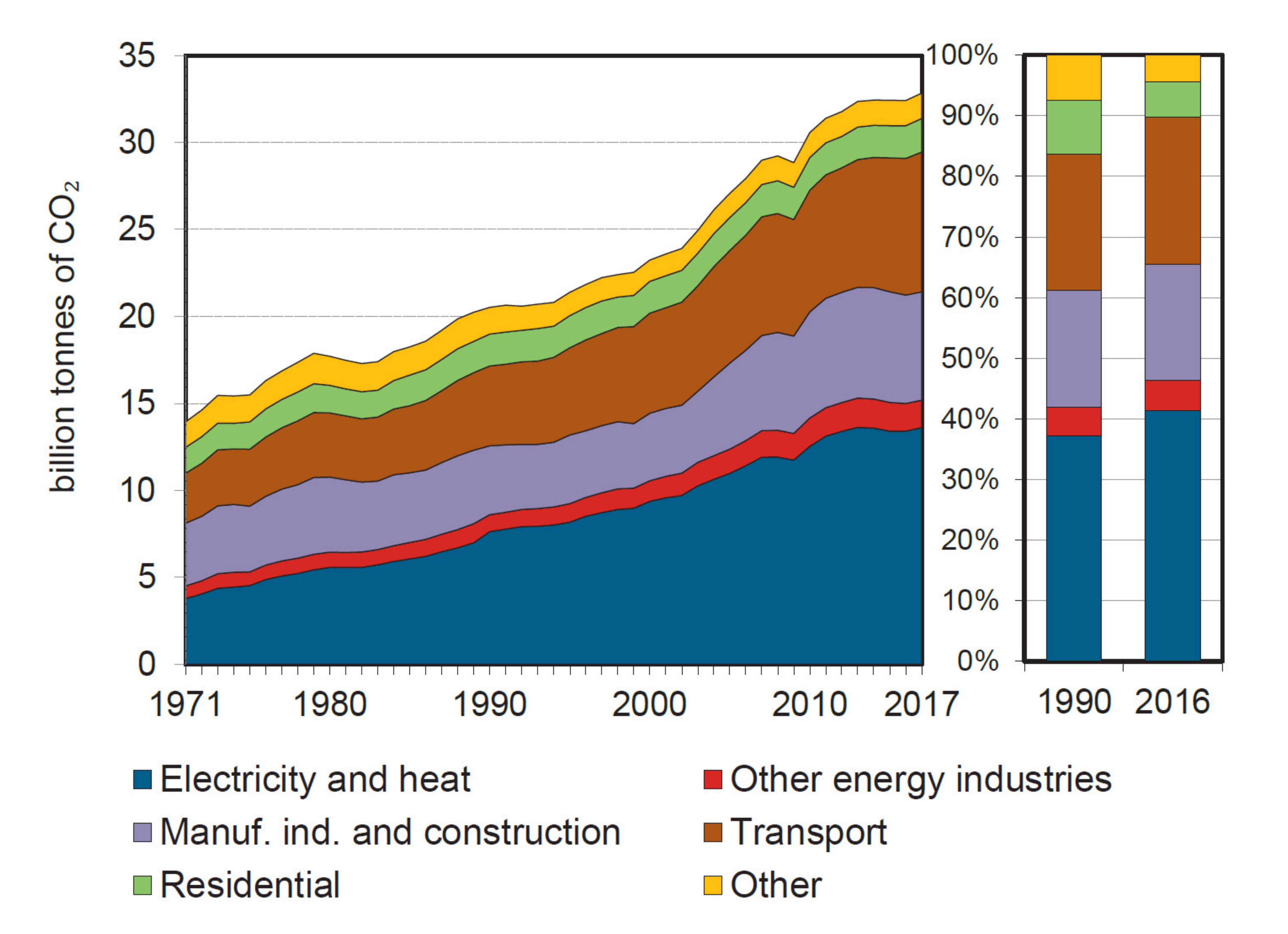
Figure 1. Global CO2 emissions by sector from 1971 to 2017 according to the International Energy Agency (IEA) [2]. Source: IEA (2019) CO2 Emissions from Fuel Combustion—Highlights. All rights reserved.
Applsci 10 04988 g001
Figure 2. Current-voltage (I-V) and power-voltage (P-V) characteristic curves of a photovoltaic (PV) module [29].
Applsci 10 04988 g002
Figure 3. Conventional PV structures. (a) Centralized structure; (b) string structure; (c) module structure [31].
Applsci 10 04988 g003
Figure 4. Overall PV/grid-tied electric vehicle (EV) charging system structure [13,31].
Applsci 10 04988 g004
Figure 5. Operating modes for the PV-grid-tied EV charging system. (a) PV to battery; (b) grid to battery; (c) PV and grid to battery; (d) PV to grid; (e) vehicle-to-grid (V2G) [13].
Applsci 10 04988 g005aApplsci 10 04988 g005b
Figure 6. Schematic diagram of non-isolated DC–DC converters. (a) Boost converter; (b) buck-boost converter; (c) Cuk converter; (d) single-ended primary-inductor converter (SEPIC) [29,60].
Applsci 10 04988 g006
Figure 7. Schematic diagram of bidirectional AC-DC inverter topologies. (a) one-phase half-bridge (HB) bidirectional boost inverter; (b) one-phase voltage source inverter (VSI) full-bridge (FB) bidirectional boost inverter; (c) one-phase one-stage isolated bidirectional inverter with output low pass filter (LPF); (d) FB bidirectional inverter with leakage current reduction; (e) three-phase FB bidirectional inverter; (f) three-level three-phase diode neutral point clamped (NPC) inverter; (g) three-phase bridgeless boost inverter; (h) three-phase Vienna rectifier [13,34,46,47,56,57,61,62,63,64].
Applsci 10 04988 g007aApplsci 10 04988 g007b
Figure 8. Schematic diagram of non-isolated bidirectional DC–DC converters. (a) Bidirectional converter with coupled inductors and output filter; (b) zero-voltage-switching (ZVS) interleaved HB converter; (c) HB converter with resonant circuit; (d) zero-voltage-transition (ZVT) interleaved converter with resonant circuit; (e) ZVS HB converter with coupled inductors; (f) three-phase interleaved buck converter [13,34,48,49,70,71,72,73,74,75].
Applsci 10 04988 g008aApplsci 10 04988 g008b
Figure 9. Schematic diagram of isolated bidirectional DC–DC topologies. (a) ZVS DAB converter; (b) phase-shift FB converter; (c) FB LLC resonant converter; (d) ZVS FB converter with capacitive output filter; (e) four interleaved flyback convert [13,17,38,50,77,78,79].
Applsci 10 04988 g009aApplsci 10 04988 g009b
Figure 10. Schematic diagram of a Z-source inverter (ZSI) for a PV/grid-tied system [55].
Applsci 10 04988 g010
Table 1. SAE J1772 US Standard for EV/PHEV charging power levels [17,22,24,25,26].
TypeLevelSupplied Voltage Range (V)Maximum Current (A)Output Power Level (kW)Estimated Charge Time (hours)
AC charging
(on-board chargers)
Level 1120 Vac
(1-phase)
up to 16 Aup to 1.92 kW7–17 h
Level 2208–240 Vac
(1-phase)
up to 80 Aup to 19.2 kW0.4–7 h
Level 3208–240 Vac
(1 and 3-phase)
up to 400 Aup to 96 kWLess than 0.5 h
DC charging
(off-board chargers)
Level 1200–450 VDCup to 80 Aup to 36 kW0.4–1.2 h
Level 2200–450 VDCup to 200 Aup to 90 kW0.2–0.4 h
Level 3200–600 VDCup to 400 Aup to 240 kW0.1–0.2 h
Table 2. Comparison of non-isolated DC–DC converters for the PV stage.
Ref.DC-DC TopologyAdvantagesDisadvantagesApplications
[29,42,58]Boost Converter
  • The reverse current is blocked by the free-wheeling diode
  • It is remarkably the most effective topology at any price
  • Less ripple on output side
  • Cheaper filter components
  • It has output non-inverted polarity
  • MPP cannot be tracked under low irradiation conditions
  • It has a non-operational region
  • It cannot achieve values near the modules VOC
  • Not suitable for high variability environmental conditions
  • Low input voltage and high output voltage required
[29,42]Buck-Boost Converter
  • This converter can operate in any operating region of the PV module (from ISC to VOC)
  • It is the only topology capable of tracking load resistance
  • It is able to track the modules’ MPP at varying conditions of irradiance, temperature and load
  • There are many harmonic components in the input current
  • It has a high input voltage ripple
  • It has substantial noise issues
  • It is more complex and expensive
  • It has a high current and voltage stress on the switch
  • Cost is inversely proportional to efficiency
  • Lower efficiency than the boost converter
  • The switch drive is floated
  • It has output inverted polarity
  • Used for charging systems
[29,42]Cuk Converter
  • This converter can operate in any operating region of the PV module (from ISC to VOC)
  • Prevent large harmonics at the input
  • It is more reliable and less noisy than other topologies due to the inductors at the input and output
  • High number of passive components
  • It has high electrical stresses on the devices
  • The switch drive is floated
  • It has output inverted polarity
  • Low voltage DC supply for electric vehicles
[29,42]SEPIC Converter
  • It has output non-inverted polarity
  • The switch drive is grounded, simplifying the gate-drive circuitry
  • Less ripple on input side due to the continuous input current
  • This converter can operate in any operating region of the PV module (from ISC to VOC)
  • More ripple on output side
  • Medium efficiency
  • Most expensive than the other topologies
  • High number of passive components
  • Low power charger systems
Table 3. Comparison of bidirectional AC–DC inverter topologies.
Ref.Inverter TopologiesAdvantagesDisadvantagesApplications
[13,18,28,38,44,45,46,61,65]One-Phase HB Bidirectional Boost Inverter
  • Two switches are employed to obtain double boost conversion at the DC bus
  • The voltage at the DC bus is almost matched by the peak-to-peak voltage of the AC source
  • Zero Voltage Switching (ZVS) can be used to enhance the efficiency of this topology
  • High forward current conditions and high voltage are the settings under which rectifier diodes work under
  • Reverse recovery issues are ongoing
  • DC-side leakage current
  • The DC bus possess harmonic currents at double the grid frequency during which the switches endure high voltage stress, ultimately creating harmonic currents
  • Low power microgrid battery interface
  • Low power EV charging
  • Low power density
[13,17,18,38,44,45,46,61]One-Phase VSI FB Bidirectional Boost Inverter
  • PWM switching can result in active rectification
  • Less voltage stress on the switches than in the 1-phase HB inverter
  • High power factor
  • DC-side leakage current
  • Medium power microgrid battery interface
[13,63]One-Stage Isolated Bidirectional Inverter with Output LPF
  • It produces an output voltage of ±VDC
  • It provides an isolation between the grid and the common DC bus
  • It is more expensive and robust
  • Low output power supply
  • High electromagnetic compatibility (EMC)
  • High power applications
[13,38,62]FB Bidirectional Inverter with Leakage Current Reduction
  • Dwindles the common-mode electromagnetic interference in the AC-side
  • Minimize the DC-side leakage current
  • It uses a split-phase single-phase as an input voltage
  • Non-ideal conditions have resulted in the continued existence of high-frequency common mode noise; despite the fact that the common mode noise of the bipolar modulation is theoretically zero
  • The AC grid possesses a low-impedance grounding scheme and as such both the positive and negative DC rails will display the generated common mode noise
  • High power factor
  • Medium power density
  • High power charging applications
[13,38,57,66,67]Three-Phase FB Bidirectional Inverter
  • An output voltage of ±VDC is created by full-bridge topology
  • When comparing equal power levels of the half-bridge topology, it displays lower switch stress and losses
  • Has a high-power factor with most of the control techniques (i.e., hysteresis current control, sinusoidal PWM, space vector modulation, sliding mode control, and one cycle control)
  • In order to reach equal voltage sharing between the split capacitors, an expensive, sophisticated and large capacitor is needed
  • A perturbation in the control scheme is caused under extreme unbalanced and nonlinear conditions stemming from a large neutral current flow through the neutral path
  • High power electric drives
  • Low cost
  • PWM controlled rectifiers
  • High power charging applications
[34,43,47]Three-Level Three-Phase Diode NPC Inverter
  • Supports bipolar common DC bus
  • Reduces stress on the power switching devices
  • Offers a high-power capacity
  • It is capable of producing a five-level output voltage
  • Provides a good power quality at the PCC with less harmonic currents
  • A smaller filter requirement is needed
  • Possesses superior current performance than the VSI topology.
  • Uses a large number of components
  • The positive and negative DC bus possesses unbalanced power that leads to create a lower current on the grid side, ultimately resulting in instability in the grid
  • Complex control
  • High power fast EV charging
  • High voltage drives
[17,34,57]Three-Phase Bridgeless Boost Inverter
  • The most common control schemes used for this topology include Sliding Mode Control (SMC), Hysteresis Current Control (HCC), Sinusoidal Pulse-Width Modulation (SPWM), and Space Vector Modulation (SVM)
  • Some of the proposed topologies focus on reducing the stress on the active devices while others focus on minimize the filter size
  • Unidirectional power flow, limiting V2G operations
  • Complex control
  • Has a high-power stress
  • Medium power single DC-microgrid-grid interface
  • Low cost
  • Low power quality
[17,25,34,64,68,69]Three-Phase Vienna Rectifier
  • Has fewer losses of reverse recovery currents
  • The controller uses a high frequency Pulse-Width Modulation (PWM)
  • Free neutral connection
  • Simple control
  • High power factor
  • The dead time problems are removed
  • Unidirectional power flow, limiting V2G operations
  • Uses large number of components
  • Low cost microgrid—grid interface
  • High voltage DC bus for DC microgrid
  • Fast charge applications
  • Double the line-to-line voltage is the minimal boost voltage for this inverter
Table 4. Comparison of non-isolated bidirectional DC–DC converter topologies.
Ref.Charger TopologiesAdvantagesDisadvantagesApplications
[13,38,48,70,71]Bidirectional Converter with Coupled Inductors and Output Filter
  • Step down/up functions
  • It does not require an extra filter circuit since the coupled inductor acts as a filter
  • A smoother control is offered by the coupled inductor
  • It has an efficiency of 95% when operating at rated power despite not having ZVS and Zero Current Switching (ZCS)
  • Least expensive than other topologies
  • Faces the right half plane zero effect within the output voltage to duty cycle in continuous conduction mode (CCM)
  • The dynamic performance of the converter is limited
  • Require a floating drive since the switch is not near ground
  • Low power solar PV charger
  • Solar PV power supply
[17,38,49]ZVS Interleaved HB Converter
  • The use of the snubber capacitor allows to achieve the soft switching turn off at negative voltage instead of zero
  • Turn on soft switching is achieved using a complementary gate signal control
  • The input ripple current is reduced
  • The inductor size is reduced due to the use of the interleaved technique
  • It is the most expensive among the other topologies discussed
  • High power low ripple power supply
  • Portable programable power supply
[13,38,72]HB Converter with Resonant Circuit
  • High voltage gain
  • Can handle high power in charge and discharge mode
  • Using the auxiliary resonant circuit, the ZVS and ZCS are implemented
  • Reduced voltage stress on the switches
  • It has a reduced output voltage due to the equivalent series resistance (ESR) drop of the active and passive devices
  • The operation of couple inductors produce a considerable input current ripple
  • Low cost battery continuous duty charging application
  • Uninterruptable power supply
  • Not suitable for high power applications
[13,38,73]ZVT Interleaved Converter with Resonant Circuit
  • The input ripple current is reduced by using the interleaving technique
  • High voltage gain
  • Low switch current and voltage stresses
  • The reverse recovery effects can be minimized since the rectifier diodes realize ZCS condition
  • There are not drawbacks mentioned on the literature of the proposed topology
  • Low ripple programable power supply
  • Robust closed loop control
[13,38,74]ZVS HB Converter with Coupled Inductors
  • For heavy loads, by selecting a ZVS mode, it is obtained a high efficiency
  • For light loads, by selecting a hard-switching mode, it is also obtained a high efficiency
  • At light conditions the efficiency decrease
  • When the load decrease, the recycled energy increases
  • Medium power constant load DC power supply
[34,75,76]Three-Phase Interleaved Buck Converter
  • Efficiency is improved by using separate inductors
  • The current is shared between the multi-phase modules
  • The number of phases is inversely proportional to the inductor size
  • In phase current, it has a high THD
  • High power DC drive
  • Fast DC charger
  • Applications with isolated front low-frequency transformers
Table 5. Comparison of isolated bidirectional DC–DC converter topologies.
Ref.Charger TopologiesAdvantagesDisadvantagesApplications
[13,38,77]ZVS DAB Converter
  • By using snubbers capacitors, ZVS mode can only be achieved for specific conditions
  • It has low switching losses
  • Higher switching frequencies cause high turn-off losses
  • ZCS mode is not enabled
  • High voltage applications
  • High level of reliability required
[17,34,80,81]Phase-Shift FB Converter
  • Primary switches require soft-switching
  • Simple control
  • The freewheeling interval possess high current flow
  • Achieve higher efficiency that conventional FB topologies
  • The PWM control reduce switching losses and current stress on devices
  • High voltage stress on the rectifier bridge
  • Hard switching losses and the loss of guarantee with ZVT operation are consequences of PHEV current requirements dropping below minimum critical output current value
  • High power and high frequency applications
[22,34,78,82,83,84]FB LLC Resonant Converter
  • It can achieve high efficiency in a full range of ZVS for primary switches, in high voltage operations and at the resonant frequency
  • No reverse recovery current in addition to an absent oscillation voltage across the rectifier diodes
  • The output voltage is able to be regulated during the hold-up time
  • The transformer and filter designs are complex
  • When the battery voltage is low, its operation is less efficient
  • Energy conversion systems
  • Power supply
  • PV applications
[22,79]ZVS FB Converter with Capacitive Output Filter
  • The diode rectifier ringing is minimized inherently on the current fed topologies with capacitive output filter
  • At ZVS mode can achieve high efficiency (approx. 95.7%)
  • Has reverse recovery losses in the secondary rectifier diodes
  • Has high voltage ringing
  • High power applications
[50]Four Interleaved Flyback Converter
  • For bidirectional operation, the antiparallel diodes and MOSFETs are used on both sides of the transformer
  • As a result of the two MOSFETs connected in parallel on the secondary side, there was a reduction in conduction losses
  • Provides isolation as required by the EV charging standards
  • Use less switches than the DAB and resonant converter topologies
  • In both charging and V2G operation a quasi-resonance (QR) mode is operated
  • Cause a reduction in turn-on losses resulting from low-voltage switching (LVS) or ZVS
  • Turn-off losses approach zero, because resonant capacitors absorb turn-off energy
  • It is more expensive than other topologies due to the transformer used
  • The topology is more robust
  • Suitable for low power applications, however when using SiC devices in a QR mode, high efficiency at high powers can be achieved