Article

Energy and Exergy Analyses of an Existing Solar-Assisted Combined Cycle Power Plant

1
Institute for Energy Systems and Technology, Mechanical Engineering Department, Technical University of Darmstadt, 64287 Darmstadt, Germany
2
Mechanical Power and Energy Department, Military Technical College, Cairo 11766, Egypt
*
Author to whom correspondence should be addressed.
Appl. Sci. 2020, 10(14), 4980; https://doi.org/10.3390/app10144980
Submission received: 12 June 2020 / Revised: 13 July 2020 / Accepted: 15 July 2020 / Published: 20 July 2020

Abstract

:
Solar-assisted combined cycle power plants (CCPPs) feature the advantages of renewable clean energy with efficient CCPPs. These power plants integrate a solar field with a CCPP. This integration increases the efficiency of solar power plants while decreasing the CO2 emissions of the CCPPs. In this paper, energy and exergy analyses were performed for an existing solar-assisted CCPP. The overall thermal efficiency and the exergetic efficiency of each component in the power plant were calculated for different solar field capacities. Also, a parametric study of the power plant was performed. The analysis indicated that the exergetic efficiency of the power plant components has its lowest value in the solar field while the condenser has the lowest exergetic efficiency in the combined cycle regime of operation. Further, a parametric study revealed that the thermal efficiency and the exergetic efficiency of the power plant as a whole decrease with increasing ambient temperature and have their highest values in the combined cycle regime of operation. Owing to these results, an investigation into the sources of exergy destruction in the solar field was conducted.

1. Introduction

The world society actively supports measures aimed at facilitating flexible and low-carbon energy economy. These actions mainly include the promotion of renewable energy sources for power generation with possible electrification of the heating and transport sectors.
Concentrated solar power (CSP) plants use steam to produce energy, similar to the conventional steam power plants. They consist of a solar field and a power block, and they may have an energy storage system (optional).
Many types of collectors have been developed to be used in CSP technology. Parabolic trough collectors (PTCs) have been used in many CSP plants. Parabolic trough power plants are ready for use today because they were tested on a commercial basis [1]. This has been proven in California since 1985 with parabolic trough power plants, with 354 MW of installed capacity [2], which have succeeded in commercial operation and generate electricity using a steam turbine connected to a generator as conventional power plants.
However, the increasing share of renewables is raising awareness of a critical challenge. Renewables normally provide fluctuating feed-in into the electricity grid so that energy reserves, e.g., energy storage systems or conventional thermal power plants such as nuclear power plants and combined cycle power plants (CCPPs), are required to achieve a balance between current electricity supply and demand. Also, to increase the profitability of the CSP plants, CSP technologies have been integrated with conventional plants.
The high thermodynamic efficiency of the CCPPs has attracted the construction of these power plants worldwide. On the one hand, the nominal process efficiency of a large-scale CCPP with a net electrical power of about 605 MWel per unit can reach levels greater than 60% [3,4,5,6]. On the other hand, state-of-the-art coal-fired power plants reach a net thermal process efficiency of about 46% with single reheat and several low-pressure and high-pressure feedwater preheaters [7]. According to the International Energy Agency (IEA) in 2018, gas-fired power generation accounted for approximately 24% of the total share of worldwide electricity generation, dominated by CCPPs.
The CCPPs have the advantage of absorption of the waste heat in the flue gas of a gas turbine using a heat recovery steam generator (HRSG) installed downstream of the gas turbine. The integration of solar energy into this technology is an effective method for cleaner and cheaper power generation.
CSPs integrated within CCPPs are known as integrated solar combined cycle (ISCC) power plants. ISCC power plants consist of a solar field and a solar steam generator integrated into a conventional CCPP. This ISCC system improves the solar-to-electricity conversion efficiency [8,9,10] and the economic feasibility of the CSP plants. In addition, it increases the solar share, which leads to saving the fossil fuels used in these plants [10] while decreasing the CO2 emissions [11].
B. Kelly et al. [12] demonstrated that the ISCC power plant concept presents an effective path for the continued development of PTC technology regarding the solar thermal-to-electric conversion efficiencies and the solar energy levelized energy cost (LEC). J. Dersch et al. [11], in collaboration with the International Energy Agency SolarPACES (Solar Power and Chemical Energy Systems) organization, studied the advantages and disadvantages of ISCC systems compared with solar electric generation systems (SEGS) and conventional CCPPs. The study showed the environmental and economic benefits of each ISCC configuration.
G. Bonforte et al. [13], P. Iora et al. [14], M. Mehrpooya et al. [15], and A. Baghernejad and M. Yaghoubi [16] implemented exergetic analyses of ISCC power plants. G. Bonforte et al. [13] developed an exergo-environmental and exergo-economic model to analyze an ISCC power plant in Southern Poland under the design conditions. The results showed that the CO2 emissions were reduced by 9%. P. Iora et al. [14] presented a novel allocation method for the electricity produced in an ISCC based on the exergy loss approach by implementing internal exergy balances. They showed that this method is reliable and as good as the conventional Separate Production Reference method. M. Mehrpooya et al. [15] constructed a model using ASPEN HYSYS simulation software and MATLAB code to exergetically analyze an ISCC with a high-temperature energy storage system. It was found that the largest exergy losses were at the solar collector, the energy storage system, and the combustor.
A. Baghernejad and M. Yaghoubi [16] carried out energy and exergy analyses for an ISCC in Yazd, Iran using the design data of the power plant. The results showed that the energy and exergy efficiencies of this power plant are higher than those for a simple CCPP without a solar contribution and those for steam power plants with PTC technology. O. Behar et al. [17] simulated the performance of the first ISCC in Algeria, under HassiR’mel climate conditions. The results showed that the output power and the thermal efficiency increased at daytime than at night by 17% and 16.5%, respectively.
S. Wang et al. [18] analyzed the performance variation of the solar field and overall ISCC using advanced exergy analysis methods and hourly analysis within a typical day. The results showed that increasing the solar energy input to the ISCC system decreases the exergy destruction of the Brayton cycle and increases the exergy destruction of the Rankine cycle.
In the literature, one can find several papers regarding the investigation of ISCC power plants applied to different atmospheric conditions. The originality of this work is the parametric study of the energy and exergy analyses regarding an existing ISCC power plant in Egypt, under Kureimat climate conditions, as a whole and for the main components in the ISCC power plants. This work aims to identify the sites of major exergy destruction, clarify the reasons for exergy destruction in these sites, and attempt to clarify how to decrease the exergy destruction in this type of power plant. Besides this, given the challenges for the electricity market with the continuing expansion of intermittent renewables, in this work, we investigate the operational flexibility of ISCC power plants.
In this paper, we start with a description of the ISCC power plant under investigation, and we provide the method and the equation for the calculation of energy and exergy parameters. Then, we show the influence of ambient temperature and solar heat input on the plant performance. Finally, on the basis of these results, we investigate the sources of exergy destruction in the solar field and the combustion chamber to identify the possibility to enhance the performance of these components.

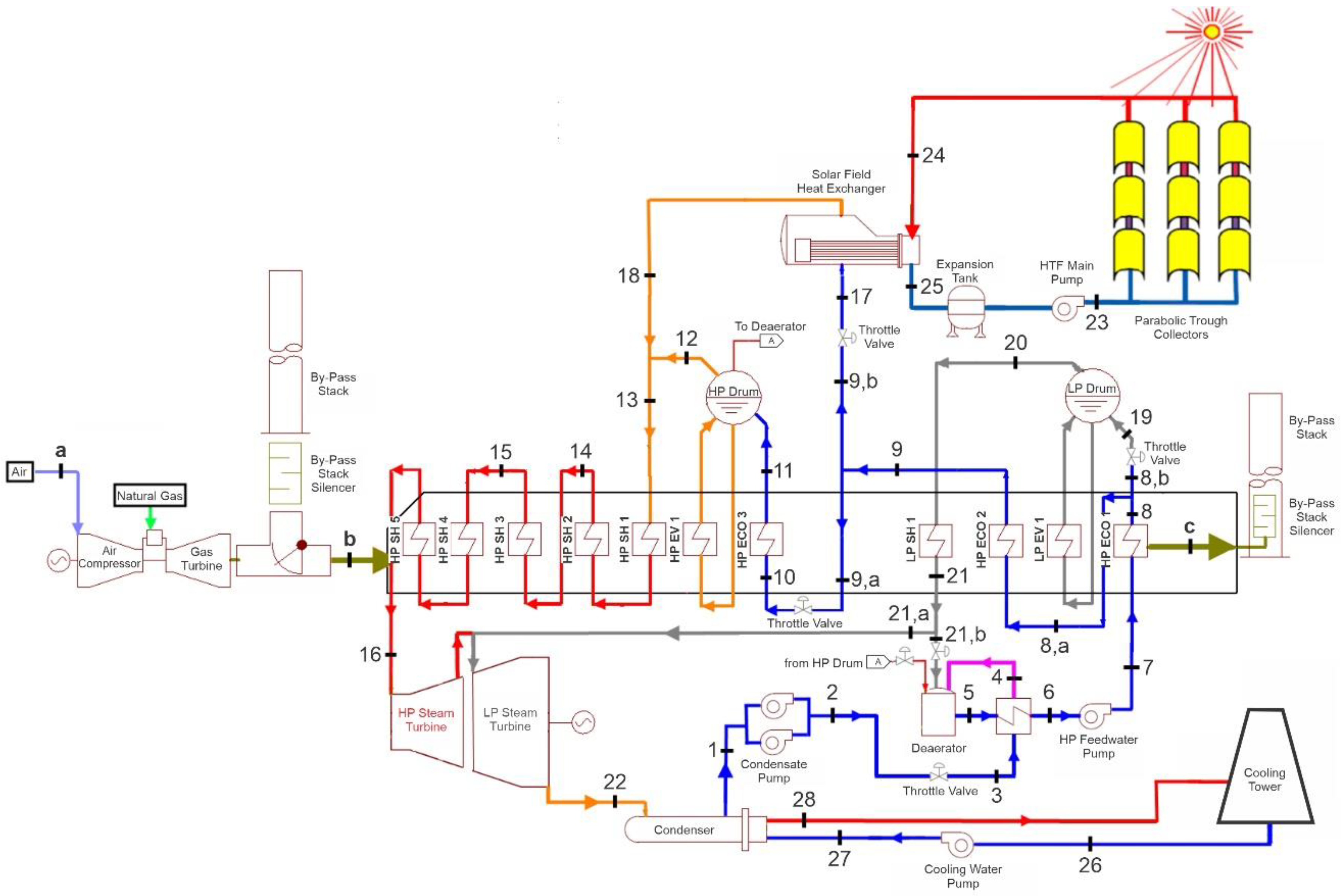
2. Plant Description

The ISCC power plant in Kureimat, Egypt is located at a northern latitude of 29°16′ and eastern longitude of 31°15′. It has 135 MW total power capacity, comprising a solar field with an electrical output of 20 MW and a combined cycle field with a power of 115 MW [19]. The integration of a combined cycle with the solar field ensures the delivery of the required electricity contribution to the grid regardless of solar radiation conditions.

2.1. Solar Field

The solar field comprises parallel rows of solar collector arrays and typical glass mirrors of 61 MW installed thermal capacity. The solar field comprises 40 loops, each loop having four parabolic trough collectors (type Skal-ET 150 designed by TSK Flagsol Engineering GmbH), and each collector has an aperture area of 817.15 m2.
The solar heat transfer from the solar field collectors (PTCs) to the steam cycle uses a heat transfer fluid (HTF) system. The HTF is Therminol VP-1 from Solutia (ultra-high-temperature, liquid/vapor phase fluid) and operates between 12 °C and 400 °C (54–750°F) [20,21]. The HTF system is designed for an HTF mass flow of 250 kg/s at full load (61 MW of solar field thermal power output). Hot HTF returning from the solar field at 393 °C is pumped through the solar heat exchanger. The HTF leaves the solar heat exchanger at 293 °C and is pumped back into the solar field, as shown in Table 1.

2.2. Combined Cycle

The combined cycle field consists of one MS6001FA heavy-duty gas turbine with a generator of a rated electric power output of 70 MW at 20 °C ambient dry bulb temperature. It has one HRSG that receives about 206 kg/s flue gas at about 600 °C from the gas turbine at full load operation. The flue gas leaves the HRSG at about 100 °C. Under the rated conditions of the gas turbine and HRSG, full load operation and solar heat input of 50 MW and 20 °C ambient dry bulb temperature, the steam turbine generator output is about 65 MW.
The HRSG of the ISCC power plant in Kureimat comprises three high-pressure economizers (HP ECO), a high-pressure evaporator (HP EV), a high-pressure steam drum (HP Drum at a pressure about 80 bar), and five high-pressure superheaters (HP SH) for a feed of the high-pressure section of the steam turbine, as shown in Figure 1. Besides this, it includes a low-pressure evaporator (LP EV), low-pressure steam drum (LP Drum at a pressure about 11 bar), and low-pressure superheater (LP SH) for a feed of the steam turbine low-pressure section. The solar-generated steam is injected into the high-pressure drum.

3. Thermodynamic Analysis

The ISCC was evaluated assuming steady-state operation, with no accounting for thermal capacitance. This assumption works fairly well through the majority of the operating day but creates some problems in the morning when the solar field is warming up.

3.1. Energy Balance

The net rate of heat input to the ISCC ( Q ˙ I S C C , i n ) is given by
Q ˙ I S C C , i n = Q ˙ f u e l + Q ˙ i n c
where Q ˙ f u e l is the rate of heat addition to the ISCC from the fuel combustion and Q ˙ i n c is the absorbed incident solar radiation. The heat from the fuel combustion ( Q ˙ f u e l ) as a function of the fuel flow rate ( m ˙ f u e l ) and the fuel heating value ( H v ) is given by
Q ˙ f u e l = m ˙ f u e l H v
and the heat from the absorbed incident solar radiation ( Q ˙ i n c ) as a function of the direct normal insolation ( D N I ), incidence angle ( θ ), incidence angle modifier ( I A M ), and solar collectors’ aperture area ( A m i r r o r s ) is given by
Q ˙ i n c = D N I c o s θ I A M A m i r r o r s .
Here, the incidence angle modifier ( I A M ) is the correlation of the losses from the collectors due to additional reflection and absorption by the glass envelope, and it can be calculated as follows:
I A M = 1 + 0.000884 θ cos θ 0.00005369 θ 2 cos θ
and the solar collectors’ aperture area ( A m i r r o r s ) is calculated from the number of solar field collectors ( N c o l l e c t o r s ) and the width ( W c o l l e c t o r ) and length ( L c o l l e c t o r ) of the collectors as follows:
A m i r r o r s = N c o l l e c t o r s W c o l l e c t o r L c o l l e c t o r
The electric power output of the ISCC ( W ˙ e l e c , I S C C ) is equal to the sum of the electric power outputs of the gas turbine ( W ˙ e l e c , G T ) and the steam turbine ( W ˙ e l e c , S T ) as follows:
W ˙ e l e c , I S C C = W ˙ e l e c , G T + W ˙ e l e c , S T
As a result, the overall first law efficiency of the ISCC power plant is
η I , c y c l e = W ˙ e l e c , I S C C Q ˙ I S C C , i n

3.2. Exergetic Efficiencies

Exergy-based performance analysis is the performance study of a system based on the second law of thermodynamics, which overcomes the limitations of studying the system based on the first law of thermodynamics. Exergy is a measure of the maximum useful work of a system as it proceeds to a specified final state in equilibrium with its surroundings (dead state). Exergy is destroyed in the system, not conserved as energy is.
Two different approaches are generally used to calculate the exergy efficiency of a system, one is called “brute force”, while the other is called “functional” [16].
The brute force form of exergy efficiency is used in this paper. The brute force form requires accuracy and an explicit definition of each input and output exergy term before calculating the exergy efficiency as shown in Table 2. The input exergy terms of the ISCC represent the chemical exergy of the fuel and the exergy associated with the solar thermal energy input.
So, the second law efficiency ( η I I ) (exergetic efficiency) is given by
η I I = E x e r g y   o u t p u t E x e r g y   i n p u t
The net exergy transfer by heat ( X ˙ h e a t ) at the source temperature ( T s ) and dead state temperature ( T 0 ) is given by
X ˙ h e a t = ( 1 T 0 T s   ) Q ˙ s
and the specific exergy ( Ψ ) is given by
Ψ = ( h h 0 ) T 0 ( s s 0 )
where h , h 0 , s , and s 0 are the specific enthalpy, the specific enthalpy under the dead state condition, the specific entropy, and the specific entropy under the dead state condition, respectively.
Then, the total exergy rate associated with a fluid stream ( X ˙ ) at the mass flow rate ( m ˙ ) becomes
X ˙ = m ˙ Ψ = m ˙ [ ( h h 0 ) T 0 ( s s 0 ) ] .
The exergy destruction rate in the ISCC as a whole ( I ˙ I S C C ) was obtained from
I ˙ I S C C = I ˙ c o m p r e s s o r + I ˙ C C + I ˙ G T + I ˙ S F + I ˙ S F H e x + I ˙ c o n d e n s e r + I ˙ C P + I ˙ F W P + I ˙ S T + I ˙ H R S G .

3.2.1. The Exergetic Efficiency of the Solar Field

The solar heat input from the HTF ( Q ˙ H T F ) to the water in the solar field heat exchanger is given by
Q ˙ H T F = m ˙ 23 ( h 23 h 24 ) ,
Q ˙ w a t e r = m ˙ 17 ( h 18 h 17 ) .
The exergy destruction rate in the solar field ( I ˙ S F ) is calculated from
I ˙ S F = X ˙ S F , i n X ˙ S F , g a i n
X ˙ S F , g a i n = X ˙ 23 X ˙ 24
X ˙ S F , i n = Q ˙ i n c [ 1 ( T 0 T s u n ) ]
where Tsun is the sun temperature, which equals 5777 K. The exergetic efficiency of the solar field ( η I I , S F ) is given by
η I I , S F = X ˙ S F , g a i n X ˙ S F , i n .

3.2.2. The Exergetic Efficiency of the ISCC

The fuel chemical exergy per unit time ( X ˙ f u e l ) equals
X ˙ f u e l = ζ Q ˙ f u e l
where ζ is the ratio of the chemical exergy to the net calorific value, which equals 1.04 for natural gas [23].
The exergetic efficiency of the ISCC ( η I I , C y c l e ) is given as
η I I , C y c l e = W ˙ e l e c , I S C C X ˙ I S C C , i n ,
X ˙ I S C C , i n = X ˙ S F , i n + X ˙ f u e l .

4. Results and Discussion

The performance of the ISCC power plant was analyzed under different design conditions. The analyses were performed for different solar field thermal outputs (0 MW, 50 MW, and 75 MW) and different ambient temperatures (5, 20, and 35 °C). All calculations were made based on design condition data.
The energy efficiency (first law efficiency) and the exergetic efficiency (second law efficiency) were calculated based on the heat input to the plant by the fuel and the sun.

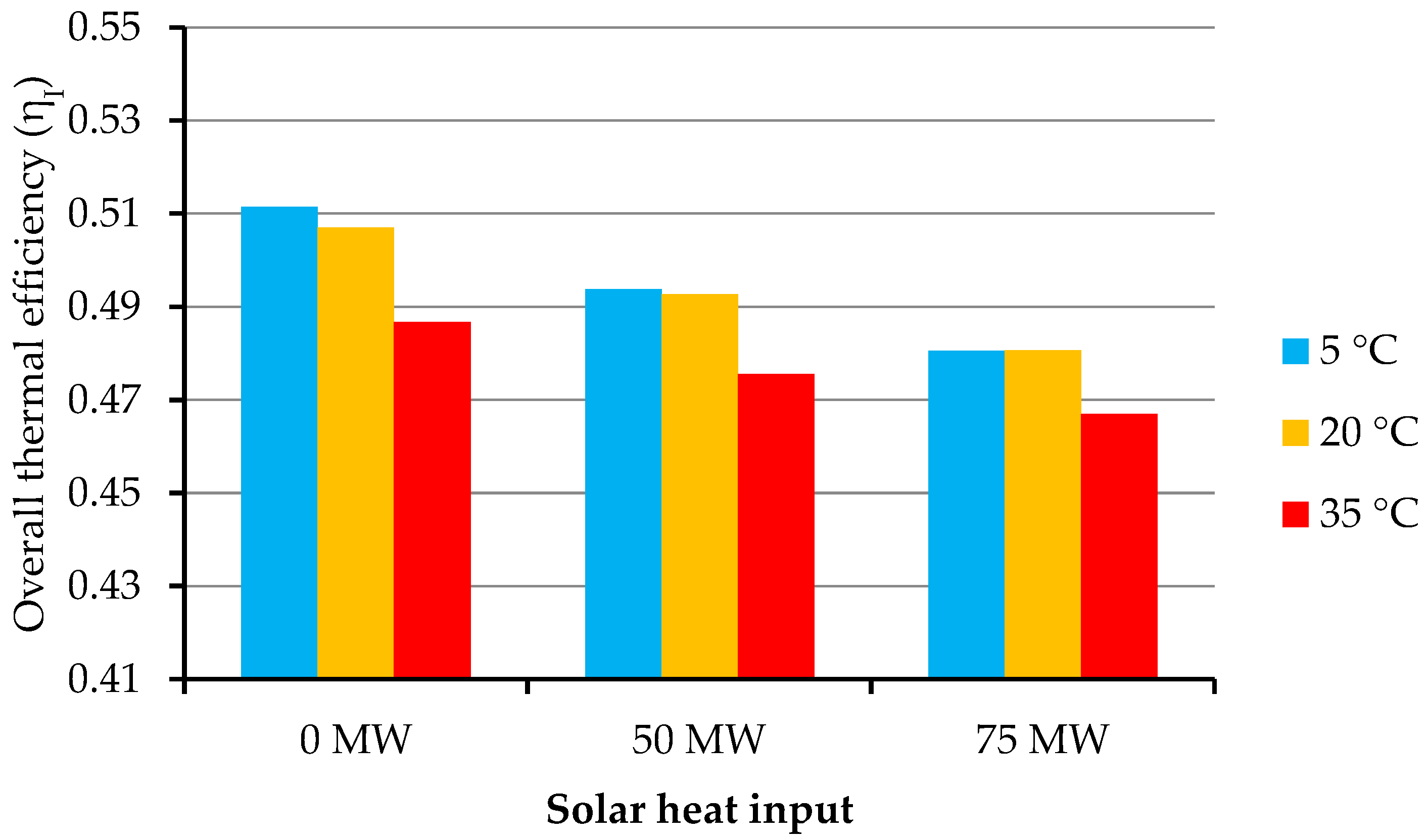
4.1. The Overall Thermal Efficiency of the ISCC Power Plant

The overall thermal efficiency of the ISCC power plant in Kureimat at different ambient temperatures for solar heat inputs of 0 MW, 50 MW, and 75 MW is shown in Figure 2.
The overall thermal efficiency of the power plant at different ambient temperatures for solar heat input equal to 0 MW, which represents the combined cycle regime, is shown in Figure 2. At no solar heat input (combined cycle regime), the thermal efficiency of the plant was reduced from 51.14% at ambient temperature 5 °C to 48.67% at 35 °C.
Figure 2 shows that the overall thermal efficiency of the ISCC decreases with increasing ambient temperature at different solar heat inputs (0, 50, 75 MW), and that appears most distinctly at ambient temperature 35 °C. This may be due to the direct effect of the ambient temperature increase on the efficiency of the condenser and the gas turbine: the condenser and gas turbine efficiency decreases with increasing ambient temperature.
The overall thermal efficiency of the ISCC is lower than the overall thermal efficiency of the plant in the combined cycle regime in all cases (different solar heat inputs and ambient temperatures). Figure 2 shows that the integration of the solar field with the combined cycle (i.e., ISCC) reduced the thermal efficiency of the power plant at all ambient temperatures. This may be because the target of the ISCC is not to increase the overall thermal efficiency of the Brayton cycle, like the combined cycle, but to increase the economic feasibility of the solar power plants. Elimination of the thermal storage system reduces the cost of the power plant [24,25,26].

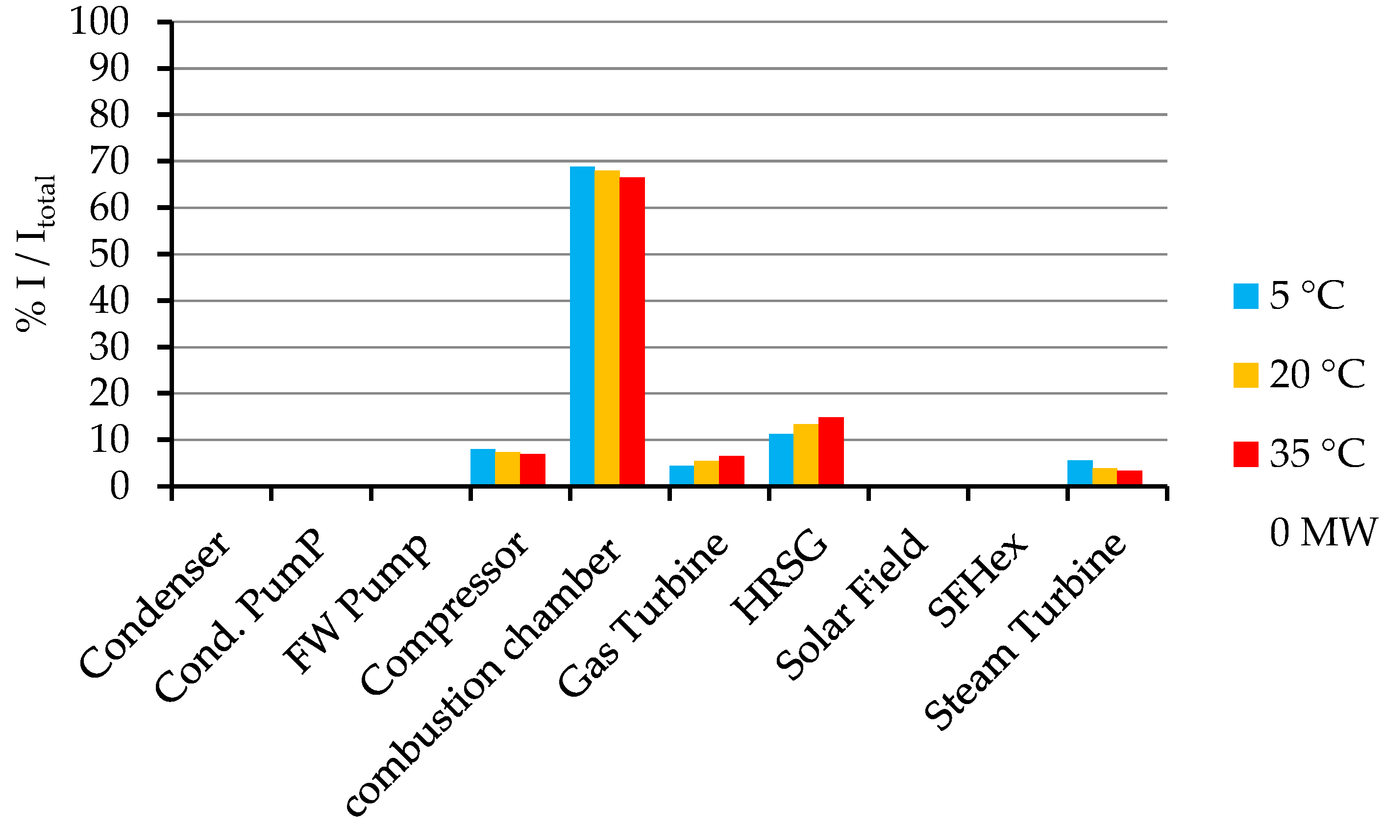
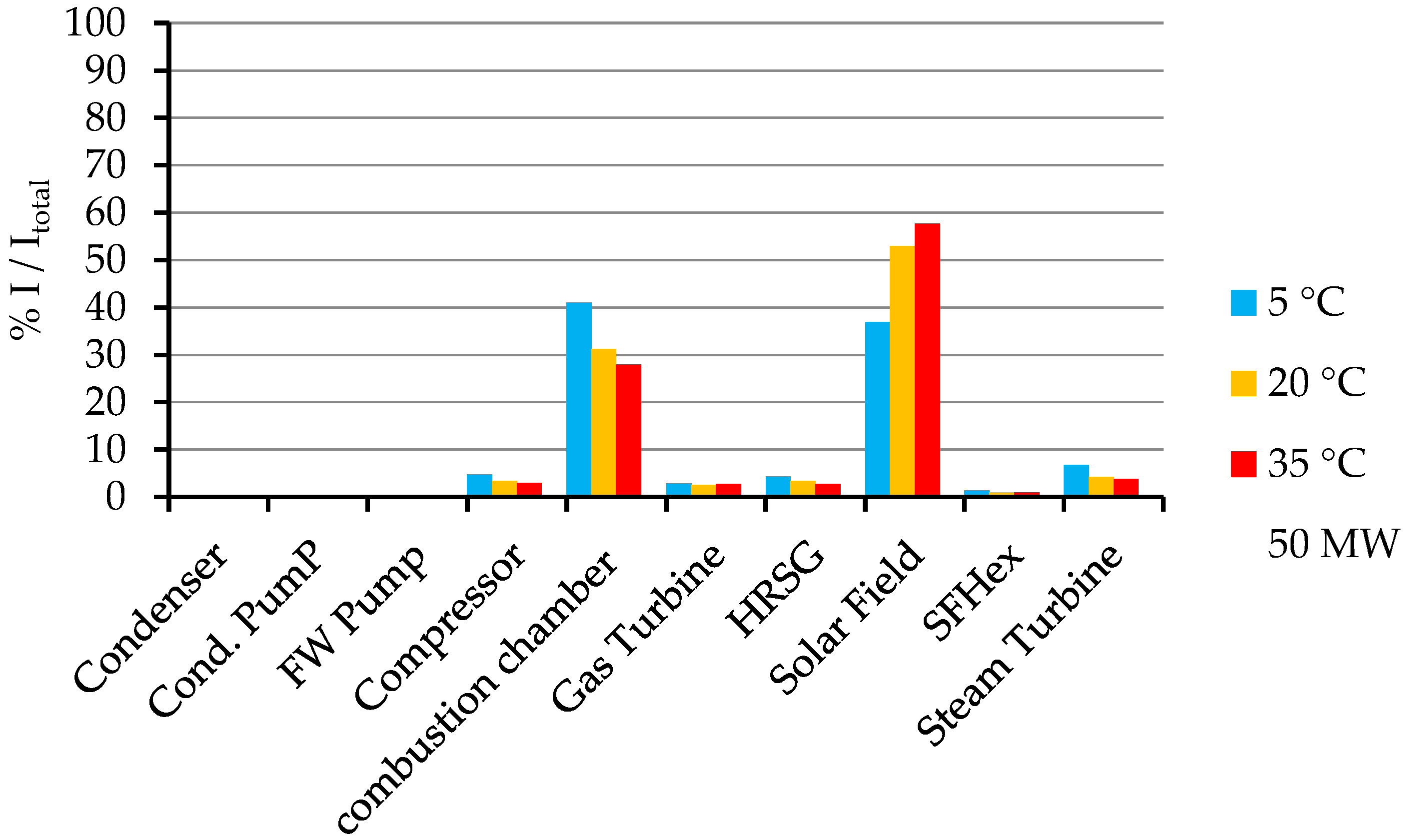
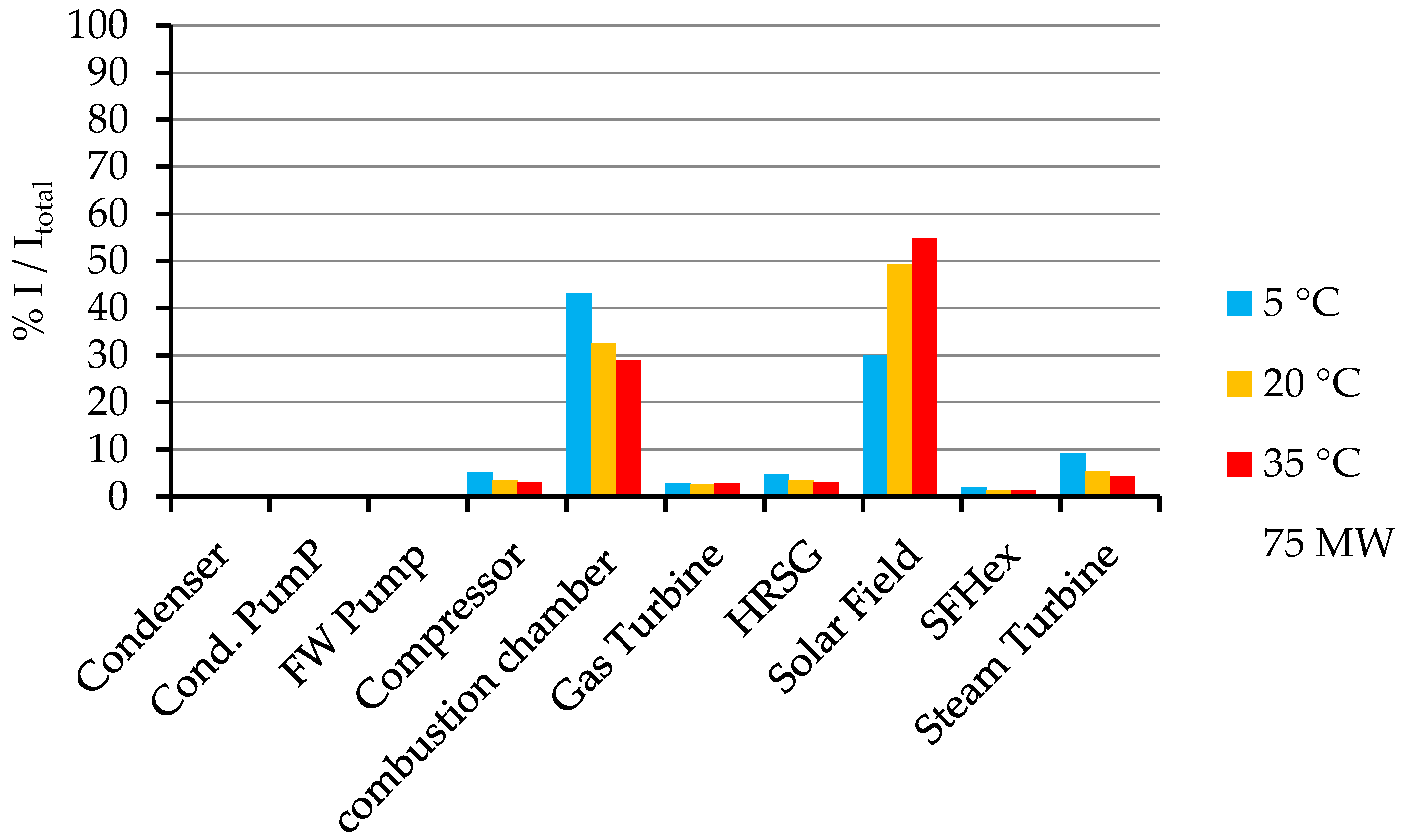
4.2. Exergy Destruction in Each Component of the ISCC as a Percentage of the Total Exergy Destruction in the Whole ISCC

The exergy destruction in each component of the ISCC and the exergy destruction in the whole ISCC were calculated for different solar heat inputs and ambient temperatures 5 °C, 20 °C, and 35 °C.
The percentages of exergy destruction in each component of the ISCC out of the total exergy destruction of the power plant at different ambient temperatures for solar heat inputs 0 MW, 50 MW, and 75 MW are shown in Figure 3, Figure 4 and Figure 5, respectively.
It is revealed in Figure 3 that the combustion chamber (CC) has the highest percentage of exergy destruction, and this value is higher in the combined cycle regime than in the ISCC regime. This may ensure that the solar field has high irreversibility weight, which affects the percentage of exergy destruction in the combustion chamber compared to its value in the combined cycle regime.
However, Figure 3 shows that the exergy destruction in the combustion chamber decreases slightly with the increase of the ambient temperature under the combined cycle regime (0 MW solar heat input).
It can be observed from Figure 4 and Figure 5 that the exergy destruction in the combustion chamber decreases significantly with the increase of the ambient temperature in the case of ISCC. This may account for the weight of exergy destruction in the solar field. Also, the exergy destruction in the solar field increases with increasing ambient temperature, in contrast to the exergy destruction in the combustion chamber.
Figure 3, Figure 4 and Figure 5 show that the combustion chamber and the solar field have the highest exergy destruction among all the subsystems. This is valid for all cases of solar heat input. It was also revealed from the values at different ambient temperatures that the exergy destruction of the solar field decreases with increasing solar thermal input.

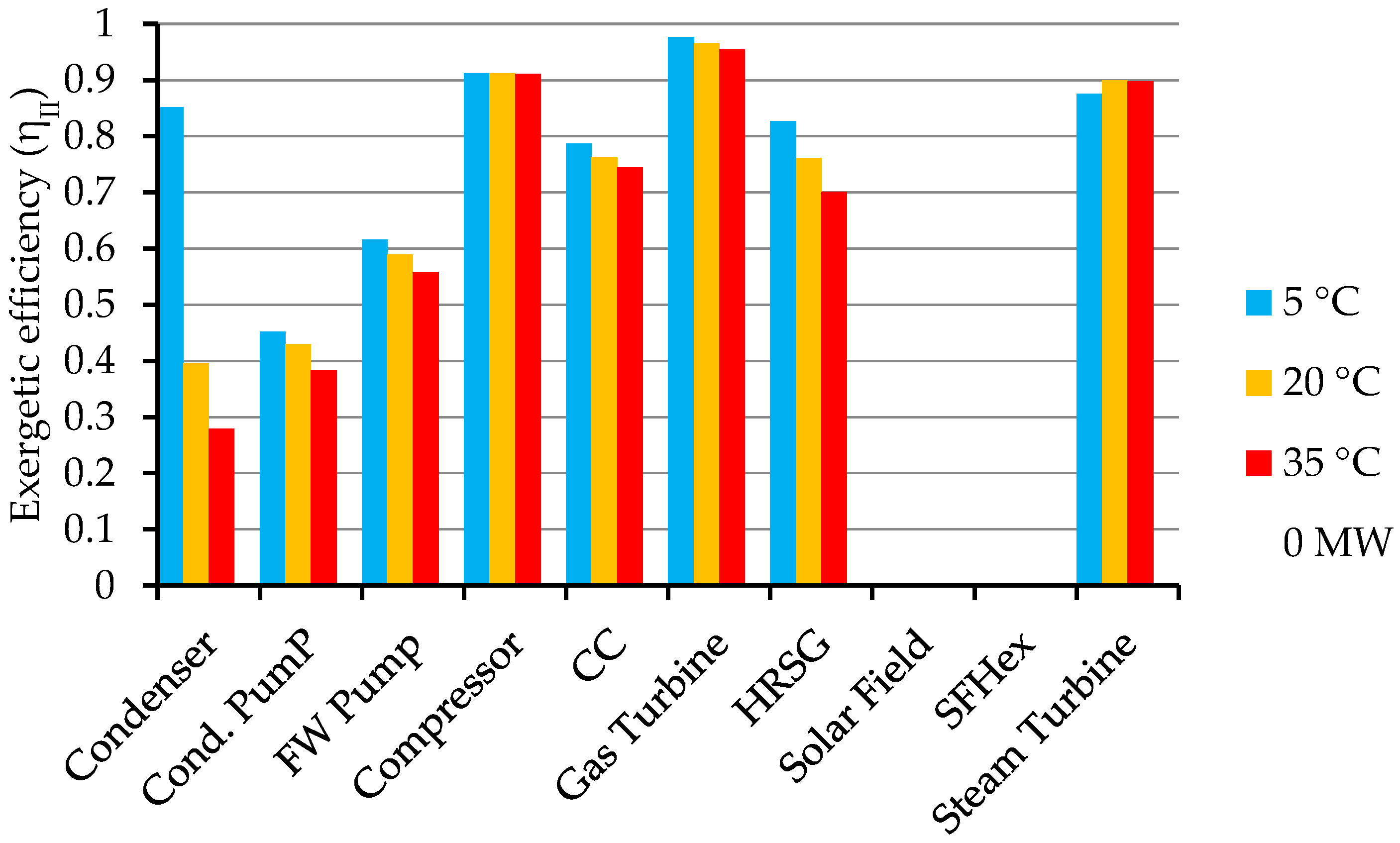
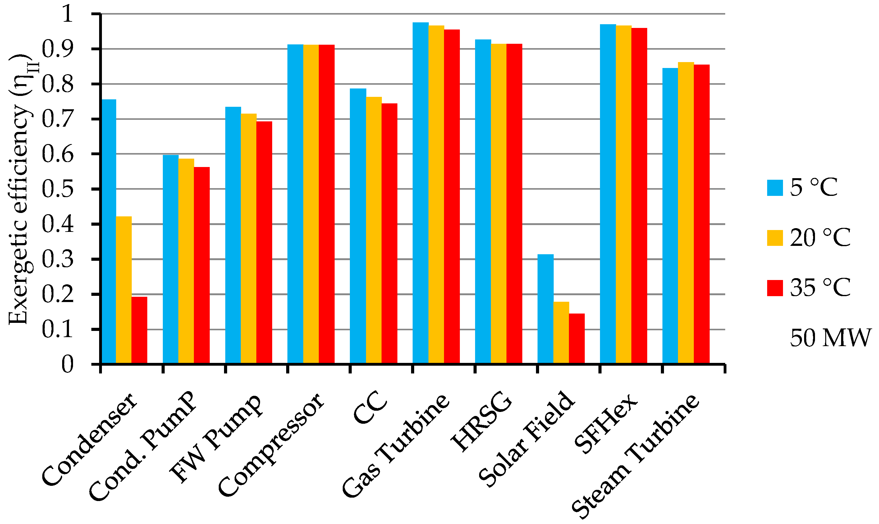
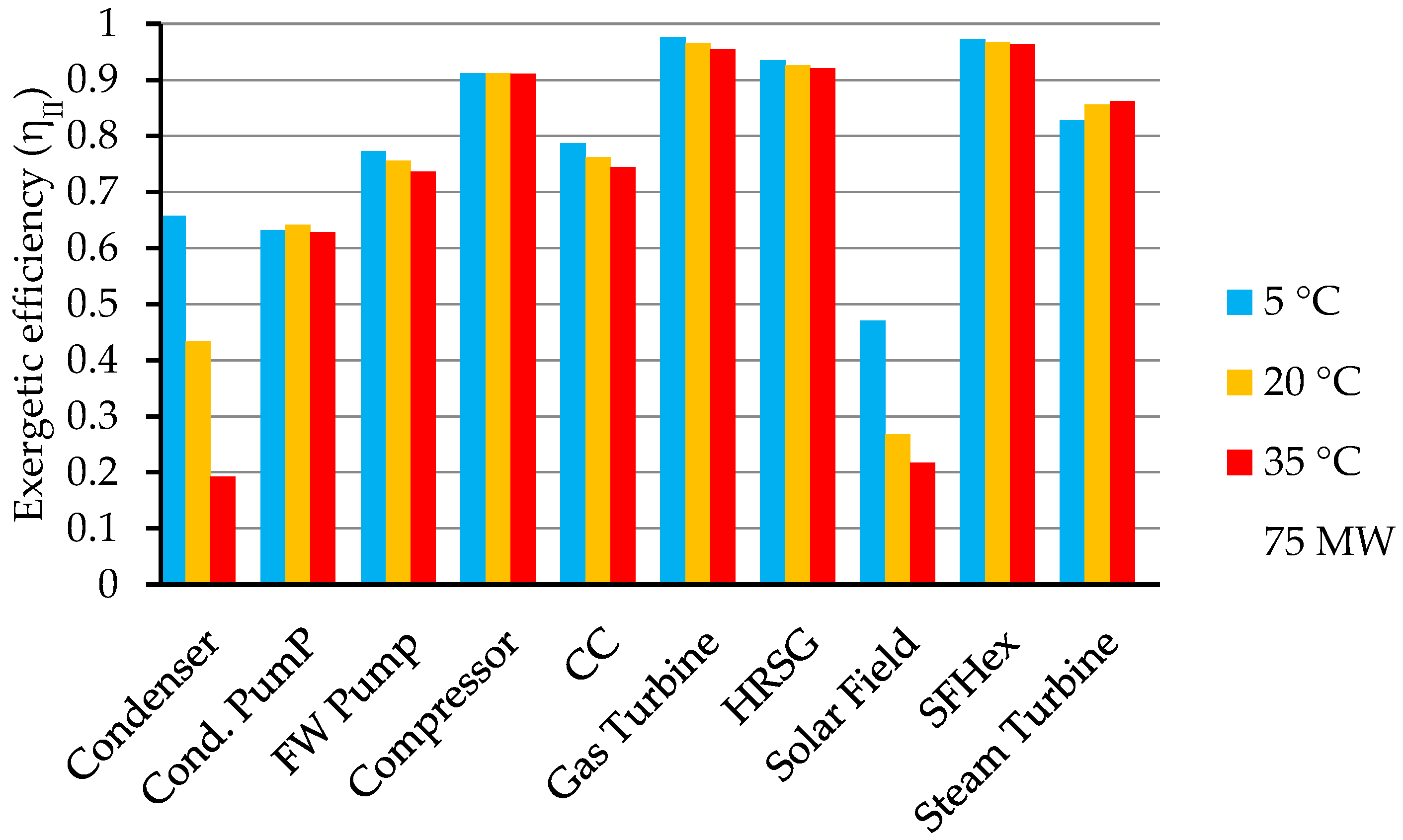
4.3. The Exergetic Efficiency of the Main Components of the ISCC

The exergetic efficiency of different components of the ISCC at different ambient temperatures for solar heat inputs 0 MW, 75 MW, and 50 MW is shown in Figure 6, Figure 7 and Figure 8, respectively.
Figure 6 depicts the exergetic efficiency of different components of the ISCC at different ambient temperatures in the absence of the solar field (solar heat input equal to 0 MW), i.e., under the combined cycle regime. Under the combined cycle regime, the condenser has the lowest exergetic efficiency except at ambient temperature 5 °C. That may be due to the decrease in the low-temperature reservoir which increases the heat dissipated to the condenser cooling water.
The exergetic efficiency of the solar field decreased from 31.3% to 14.5% when the ambient temperature increased from 5 °C to 35 °C, as shown in Figure 7. The condenser exergetic efficiency also decreased from 75.5% to 19.3% when the ambient temperature increased from 5 °C to 35 °C for solar heat input equal to 50 MW. This may be due to the decrease in the temperature difference between the exhausted steam from the low-pressure turbine and the cooling water from the cooling tower.
Figure 8 shows that the exergetic efficiency of the solar field decreased from 47% to 21.7% when the ambient temperature increased from 5 °C to 35 °C. The condenser exergetic efficiency also decreased from 65.8% to 19.3% when the ambient temperature increased from 5 °C to 35 °C for solar heat input equal to 75 MW.
As shown in Figure 6, Figure 7 and Figure 8, the exergetic efficiency of the HRSG decreased with increasing ambient temperature, and this may be due to the existence of the attemperators in the HRSG which limit the steam temperature to the setpoint value. In the HRSG installed in the Kureimat power plant, attemperators were installed at the surface of the superheaters to control the temperature at the inlet of the high-pressure steam turbine. These attemperators use water directly from the main feedwater pump of the power plant. An increase in the ambient temperature may lead to an increase in the flue gas temperature of exhaust from the gas turbine into the HRSG, and the attemperators limit the effect of this temperature increase on the temperature of the superheated steam going into the steam turbine using water directly from the main feedwater pump. This may be a reason for the decreasing exergetic efficiency of the HRSG with increasing ambient temperature as shown in Figure 6, Figure 7 and Figure 8.
Unlike the thermal efficiency [27], the exergetic efficiency of the solar field explicitly decreased with increasing ambient temperature, as shown in Figure 7 and Figure 8. This may be due to the increase of the exergy destruction in the solar field with increasing ambient temperature, as shown in Figure 4 and Figure 5.

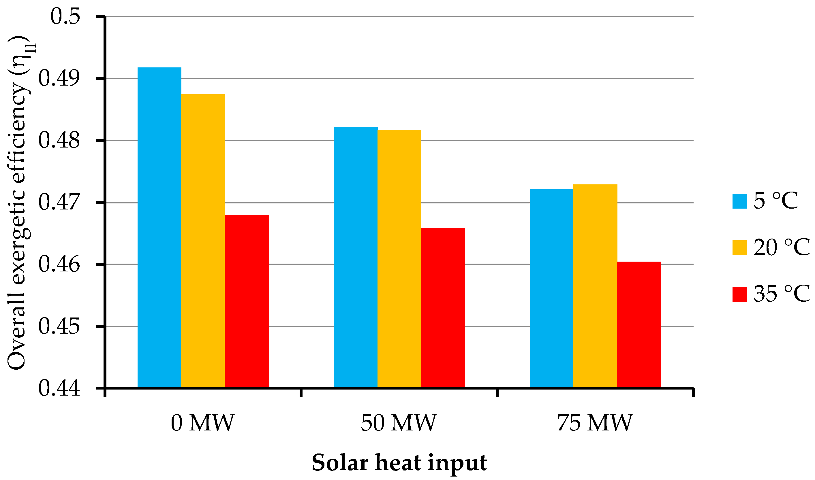
4.4. The Exergetic Efficiency of the ISCC Power Plant

The exergetic efficiency of the ISCC power plant was calculated for different solar heat power inputs. The comparison was implemented at three different ambient temperatures: 5, 20, and 35 °C.
The ISCC power plant exergetic efficiency for solar heat inputs 0 MW, 50 MW, and 75 MW at different ambient temperatures is depicted in Figure 9. The exergetic efficiency of the ISCC power plant was calculated based on the design condition data for the different solar heat power inputs.
Figure 9 reveals that the exergetic efficiency of the ISCC power plant is inversely proportional to the ambient temperature, where it decreased from 47.2% to 46% with increasing ambient temperature from 5 °C to 35 °C for solar heat input equal to 75 MW. In addition, it decreased from 48.2% to 46.58% when the ambient temperature increased from 5 °C to 35 °C for solar heat input equal to 50 MW.
Figure 9 also illustrates the exergetic efficiency of the combined cycle regime (solar heat input equal to 0 MW) at different ambient temperatures. In the absence of the solar field, the exergetic efficiency of the plant reached 49.18% and 47.21% at ambient temperatures 5 °C and 35 °C, respectively. This demonstrates that the exergetic efficiency of the ISCC power plant in Kureimat has higher efficiency under the combined cycle regime than under the ISCC regime, as shown in Figure 9. This may be due to the existence of the solar field, which needs precise design optimization of solar energy integration in a CCPP.
Like the overall thermal efficiency, the exergetic efficiency of the ISCC power plant decreased with increasing ambient temperature, mainly at ambient temperature 35 °C. This may be due to the sharp decrease in the exergetic efficiency of the condenser and the solar field with increasing ambient temperature, as shown in Figure 6, Figure 7 and Figure 8. These figures also show that the exergetic efficiency of the gas turbine and the HRSG decreased with increasing ambient temperature, and that also affected the exergetic efficiency of the ISCC power plant, as shown in Figure 9.

4.5. Investigating the Sources of Exergy Destruction

From the attained results, it is clear that the amount of exergy destruction in the various components of the ISCC is altered. This variation is assumed to be due to different reasons such as the type of device, the process, etc.
Moreover, the results showed that the combustion chamber and the solar field represent the sites of highest exergy destruction in the ISCC. In this section, an attempt is made to explore and clarify the sources of exergy destruction in the solar field and the combustion chamber to identify the possibility of enhancing the performance of these components.

4.5.1. Irreversibility in the Solar Field

The exergy destruction in the solar field is due to heat transfer between the sun and the absorber, heat transfer between the absorber and the HTF, and the friction of the viscous HTF. The exergy loss is due to the optical efficiency (the ratio of sunlight capture to incident sunlight) and the heat transfer to the surroundings.
The solar collector is considered to be the main source of exergy destruction in the solar field due to the high temperature difference in the collector. The major contribution to the exergy destruction in the solar collector is due to the heat transfer between the sun and the absorber, while the major exergy loss occurs due to optical errors [28].
It was reported that exergy destruction due to heat transfer between the sun and the absorber accounts for 35% to 40% of the total exergy destroyed. Exergy losses to the surroundings account for 5% to 10% of the total exergy destroyed [28].
It is thought that to decrease the exergy losses from the solar collector (i.e., increase the collector energetic efficiency), attention should be pointed toward improving the optical parameters of the collector (such as mirror reflectivity, transmissivity of the glass envelope, absorptivity of the heat collection element selective coating, focal length of the collectors etc.).
Regarding the exergy destruction due to heat transfer, improving that part may involve great challenges because of the existence of the finite temperature differences which are essential for the heat transfer process and cannot be avoided.

4.5.2. Irreversibility in the Combustion Chamber

The combustion process is complex. Thus, the entropy generation during the combustion process is rather high due to the complexity of that process. It was reported that oxidation of fuel during the combustion process utilizes around 1/3 of the usable fuel energy [29]. This feature of the combustion process causes it to have the highest exergy destruction. The combustion process includes diffusion, chemical reaction, heat transfer, friction, and mixing. To implement all of these subprocesses, a considerable amount of the available energy is consumed. Most of this energy is unreachable (combustion activation energy, mixing, and diffusion).
There are three major physicochemical subprocesses responsible for entropy production during the combustion process [29]:
  • Diffusion of reactants (mixing of fuel and air molecules) and chemical reaction (fuel oxidation) where energy is consumed to overcome the activation energy.
  • Heat transfer between combustion products and other neighbors of particles; this is called “internal thermal energy exchange”.
  • Mixing of combustion products with other constituents.
These processes cause exergy consumption (destruction) and thus result in a reduction in the system exergy. On one hand, all these processes destroy up to 40% of the useful exergy of the fuel. On the other hand, it was found that the dominant process of exergy destruction is the internal thermal energy exchange process. It was found that more than 2/3 of the exergy destruction in the combustion process occurs at the internal thermal exergy exchange process, while fuel oxidation is responsible for up to 30% of the exergy destruction, and the exergy destruction due to the mixing process is about 3% of the total exergy destruction of the combustion process [29].
The thermodynamically irreversible combustion process is path-dependent. To get a quantitative solution for the total entropy production during the combustion process, correct information of the sequence of the combustion process and reactions must be offered.
Many factors affect the exergy destruction in the combustion chamber. For example, the exergy destruction decreases with decreasing excess air and increasing preheating temperature. Mixing at a large temperature difference leads to high exergy destruction [30]. Also, the exergy destruction of the combustion chamber is affected by the molecular structure of the fuel, where the exergy destruction of the combustion chamber increases with the increase of the hydrocarbon chain length [31].
An attempt was made to avoid this heat transfer by introducing the concept of reversible combustion, where it was proposed theoretically to preheat the reactants to the equilibrium temperature and partial pressures without a reaction, but it could not be achieved in practice [29].
The major exergy destruction in the combustion chamber occurs during the phase of the internal thermal energy exchange between the system particles [29]. The unavoidability of the internal thermal energy exchange makes reducing the exergy destruction during the combustion process very difficult.

5. Conclusions

The objective of this study was to investigate the performance of an existing 135 MW ISCC power plant in Kureimat. The ISCC power plant was thermodynamically studied under Kureimat climatic conditions. Energy and exergy analyses were performed for the ISCC power plant as a whole at different ambient temperatures (5, 20, and 35 °C) and different solar heat inputs (0, 50, 75 MW). Moreover, the exergy destruction and the exergetic efficiency for the main components of the ISCC power plant were calculated and investigated regarding the influence of the ambient temperature and the solar heat input to identify the causes and locations of the highest thermodynamic irreversibility. The integration of solar energy into a natural gas CCPP was analyzed as a power-boosting mode.
The main conclusions of this study are as follows:
  • The solar field has the lowest exergetic efficiency (17.8%), followed by the condenser (42.2%), at ambient temperature 20 °C and solar heat input 50 MW.
  • The exergy destruction in the solar field is the largest part of the exergy destruction in the ISCC power plant (52.9% at ambient temperature 20 °C and solar heat input 50 MW).
  • The thermal efficiency and the exergetic efficiency of the ISCC decrease with increasing solar field thermal input, where it has its highest values (51.14% and 49.18%, respectively) at no solar field thermal input (combined cycle regime) and ambient temperature 5 °C.
  • The thermal efficiency and the exergetic efficiency of both the ISCC and the combined cycle (i.e., at no solar field heat input) decrease with increasing ambient temperature at different solar heat inputs (0, 50, 75 MW). This is due to the decrease of the exergetic efficiency of the gas turbine, the solar field, the condenser, and the HRSG with increasing ambient temperature.
  • The integration of a solar field with a combined cycle (i.e., ISCC) reduced the thermal and exergetic efficiencies of the power plant under the combined cycle regime due to the low thermal and exergetic efficiencies of the solar field because the solar fuel cost was considered in this study.
  • The target of the ISCC power plants is not to increase the overall thermal efficiency of the Brayton cycle, like the combined cycle, but to increase the economic feasibility of solar power plants. Elimination of the thermal storage system reduces the cost of the power plant [24,25,26]. So, this integration of a solar field is recommended regarding the given challenges for the electricity market with the continuing expansion of intermittent renewables.

Author Contributions

A.T. is responsible for the technical, analysis, writing and funding acquisition parts. A.E. has contributed strongly to the design and preparation of the investigation. A.T., A.R., A.E., F.A., and B.E. discussed the formulation and the results and contributed to the review and editing of the manuscript. All authors have read and agreed to the published version of the manuscript.

Funding

The authors appreciate the Technical University of Darmstadt for funding the publication costs for the article in an open-access journal. The corresponding author appreciates the Egyptian Government for offering the PhD scholarship.

Conflicts of Interest

The authors declare no conflict of interest.

References

  1. Zhang, H.L.; Baeyens, J.; Degrève, J.; Cacères, G.; Cac, G.; Zhang, H.L.; Baeyens, J.; Degrève, J.; Cacères, G. Concentrated solar power plants: Review and design methodology. Renew Sustain. Energy Rev. 2013, 22, 466–481. [Google Scholar] [CrossRef]
  2. Mills, D. Advances in solar thermal electricity technology. Sol. Energy 2004, 76, 19–31. [Google Scholar] [CrossRef]
  3. Ratliff, P.; Garbett, P.; Fischer, W. The new siemens gas turbine sgt5-8000h for more customer benefit. VGB Powertech 2007, 87, 128–132. [Google Scholar]
  4. Scholz, C.; Zimmermann, H.; an der Ruhr, M. First Long-Term Experience with the Operational Flexibility of the SGT5-8000H. 2012. Available online: https://www.osti.gov/etdeweb/biblio/22090573 (accessed on 1 July 2020).
  5. Vandervort, C.; Wetzel, T.; Leach, D. Engineering and validating a world record gas turbine. Mech. Eng. 2017, 139, 48–50. [Google Scholar] [CrossRef] [Green Version]
  6. Vandervort, C. Advancements in h class gas turbines and combined cycle power plants. In Proceedings of the ASME Turbo Expo 2018: Turbomachinery Technical Conference and Exposition, Oslo, Norway, 11–15 June 2018. [Google Scholar]
  7. Spliethoff, H. Power Generation from Solid Fuels; Springer Science & Business Media: Berlin, Germany, 2010; ISBN 364202856X. [Google Scholar]
  8. Behar, O.; Khellaf, A.; Mohammedi, K.; Ait-kaci, S. A review of integrated solar combined cycle system (ISCCS) with a parabolic trough technology. Renew. Sustain. Energy Rev. 2014, 39, 223–250. [Google Scholar] [CrossRef]
  9. Montes, M.J.; Rovira, A.; Muñoz, M.; Martínez-val, J.M. Performance analysis of an integrated solar combined cycle using direct steam generation in parabolic trough collectors. Appl. Energy 2011, 88, 3228–3238. [Google Scholar] [CrossRef]
  10. Rovira, A.; Montes, M.J.; Varela, F.; Gil, M. Comparison of heat transfer fluid and direct steam generation technologies for integrated solar combined cycles. Appl. Therm. Eng. 2013, 52, 264–274. [Google Scholar] [CrossRef]
  11. Dersch, J.; Geyer, M.; Herrmann, U.; Jones, S.; Kelly, B.; Kistner, R.; Ortmanns, W.; Pitz-Paal, R.; Price, H. Trough integration into power plants—A study on the performance and economy of integrated solar combined cycle systems. Energy 2004, 29, 947–959. [Google Scholar] [CrossRef]
  12. Kelly, B.; Herrmann, U.; Hale, M.J. Optimization studies for integrated solar combined cycle systems. In Proceedings of the Solar Forum 2001 Solar Energy: The Power to Choose, Washington, DC, USA, 21–25 April 2001; ASME: Washington, DC, USA, 2001; pp. 393–398. [Google Scholar]
  13. Bonforte, G.; Buchgeister, J.; Manfrida, G.; Petela, K. Exergoeconomic and exergoenvironmental analysis of an integrated solar gas turbine/combined cycle power plant. Energy 2018, 156, 352–359. [Google Scholar] [CrossRef]
  14. Iora, P.; Beretta, G.P.; Ghoniem, A.F. Exergy loss based allocation method for hybrid renewable-fossil power plants applied to an integrated solar combined cycle. Energy 2019, 173, 893–901. [Google Scholar] [CrossRef]
  15. Mehrpooya, M.; Tosang, E.; Dadak, A. Investigation of a combined cycle power plant coupled with a parabolic trough solar field and high temperature energy storage system. Energy Convers. Manag. 2018, 171, 1662–1674. [Google Scholar] [CrossRef]
  16. Baghernejad, A.; Yaghoubi, M. Exergy analysis of an integrated solar combined cycle system. Renew. Energy 2010, 35, 2157–2164. [Google Scholar] [CrossRef]
  17. Behar, O.; Kellaf, A.; Mohamedi, K.; Belhamel, M. Instantaneous performance of the first integrated solar combined cycle system in algeria. Energy Procedia 2011, 6, 185–193. [Google Scholar] [CrossRef] [Green Version]
  18. Wang, S.; Fu, Z.; Zhang, G.; Zhang, T. Advanced thermodynamic analysis applied to an integrated solar combined cycle system. Energies 2018, 11, 1574. [Google Scholar] [CrossRef] [Green Version]
  19. Brakmann, G.; Mohammad, F.A.; Dolejsi, M.; Wiemann, M. Construction of the ISCC Kuraymat. In Proceedings of the International SolarPACES Conference, Berlin, Germany, 15–18 September 2009; pp. 1–8. [Google Scholar]
  20. SOLUTIA. Data Sheet. p. 7. Available online: http://iapws.ru/MCS/Worksheets/HEDH/.%5C..%5C..%5C..%5CTTHB%5CHEDH%5CHTF-62.PDF (accessed on 17 January 2008).
  21. Eastman Selection Guide High-Performance Fluids for Precise Temperature Control 10. Available online: http://www.synthec.com.pe/media_synthec/uploads/pdf_brochures/therminol_selection_guide.pdf (accessed on 14 May 2020).
  22. Anderson, I.; Craig, A.D.; Kamal, J.A.; Veevers-Carter, P.; Govindarajalu, C.; Hassan, F. Report No: ICR2173 Implementation Completion and Results Report on a Grant In The Amount of US$ 49.80 Million to the Arab Republic of Egypt for the Kureimat Solar Thermal Hybrid Project. 2012. Available online: http://documents1.worldbank.org/curated/en/739501468021865667/pdf/ICR21730P050560C0disclosed050100120.pdf (accessed on 10 April 2012).
  23. Kotas, T.J. The Exergy Method of Thermal Plant Analysis, 1st ed.; Anchor Brendon Ltd, Tiptree, Essex: London, UK, 1985; ISBN 0408013508. [Google Scholar]
  24. Zhu, G.; Neises, T.; Turchi, C.; Bedilion, R. Thermodynamic evaluation of solar integration into a natural gas combined cycle power plant. Renew. Energy 2015, 74, 815–824. [Google Scholar] [CrossRef] [Green Version]
  25. Elmohlawy, A.E.; Ochkov, V.F.; Kazandzhan, B.I. Thermal performance analysis of a concentrated solar power system (CSP) integrated with natural gas combined cycle (NGCC) power plant. Case Stud. Therm. Eng. 2019, 14, 100458. [Google Scholar] [CrossRef]
  26. Rovira, A.; Abbas, R.; Sánchez, C.; Muñoz, M. Proposal and analysis of an integrated solar combined cycle with partial recuperation. Energy 2020, 198, 117379. [Google Scholar] [CrossRef]
  27. Temraz, A.; Rashad, A.; Alweteedy, A.; Elshazly, K. Seasonal performance evaluation of ISCCS solar field in Kureimat, Egypt. In Proceedings of the 18th International Conference on Applied Mechanics and Mechanical Engineering (AMME18), At Military Technical College Kobry El-Kobbah, Cairo, Egypt, 3–5 April 2017; pp. 91–98. [Google Scholar]
  28. Padilla, R.V.; Fontalvo, A.; Demirkaya, G.; Martinez, A.; Quiroga, A.G. Exergy analysis of parabolic trough solar receiver. Appl. Therm. Eng. 2014, 67, 579–586. [Google Scholar] [CrossRef]
  29. Dunbar, W.R.; Lior, N. Sources of combustion irreversibility. Combust. Sci. Tech. 1994, 103, 41–61. [Google Scholar] [CrossRef]
  30. Athari, H.; Soltani, S.; Rosen, M.A.; Seyed Mahmoudi, S.M.; Morosuk, T. Comparative exergoeconomic analyses of gas turbine steam injection cycles with and without fogging inlet cooling. Sustainability 2015, 7, 12236–12257. [Google Scholar] [CrossRef] [Green Version]
  31. Anheden, M. Analysis of Gas Turbine Systems for Sustainable Energy Conversion; Royal Institute of Technology: Stockholm, Switzerland, 2000. [Google Scholar]
Figure 1. A flow diagram of the integrated solar combined cycle (ISCC) power plant in Kureimat with state points illustration.
Applsci 10 04980 g001
Figure 2. The overall thermal efficiency of the power plant at different ambient temperatures for different solar heat inputs.
Applsci 10 04980 g002
Figure 3. Percentage of exergy destruction in each component of the ISCC out of the total exergy destruction of the plant at different ambient temperatures for solar heat input equal to 0 MW.
Applsci 10 04980 g003
Figure 4. Percentage of exergy destruction in each component of the ISCC out of the total exergy destruction of the plant at different ambient temperatures for solar heat input equal to 50 MW.
Applsci 10 04980 g004
Figure 5. Percentage of exergy destruction in each component of the ISCC out of the total exergy destruction of the plant at different ambient temperatures for solar heat input equal to 75 MW.
Applsci 10 04980 g005
Figure 6. Exergetic efficiency of different components of the ISCC at different ambient temperatures for solar heat input equal to 0 MW.
Applsci 10 04980 g006
Figure 7. Exergetic efficiency of different components of the ISCC at different ambient temperatures for solar heat input equal to 50 MW.
Applsci 10 04980 g007
Figure 8. Exergetic efficiency of different components of the ISCC at different ambient temperatures for solar heat input equal to 75 MW.
Applsci 10 04980 g008
Figure 9. ISCC power plant exergetic efficiency at different ambient temperatures for different solar heat inputs.
Applsci 10 04980 g009
Table 1. The solar field design parameters [15,16,22].
Solar Field Operation ParameterUnitValue
Solar Field Total Aperture Aream2130,800
Number of Collectors160
Number of Collector Loops40
Design IrradiationW/m2700
Maximum Solar Field Thermal Power OutputMW61
Output Temperature of the HTF°C393
Input Temperature of the HTF°C293
Table 2. Definitions of the exergy destruction and second law efficiency.
ComponentExergy DestructionSecond Law Efficiency ( η I I )
Pumps I ˙ p u m p = X ˙ i n X ˙ o u t + W ˙ p u m p η I I , p u m p = 1 I ˙ p u m p W ˙ p u m p
Heaters I ˙ h e a t e r = X ˙ i n X ˙ o u t η I I , h e a t e r = 1 I ˙ h e a t e r X ˙ i n
Turbine I ˙ t u r b i n e = X ˙ i n X ˙ o u t W ˙ t u r b i n e η I I , t u r b i n e = 1 I ˙ t u r b i n e X ˙ i n X ˙ o u t
Condenser I ˙ c o n d e n s e r = X ˙ i n X ˙ o u t η I I , c o n d e n s e r = X ˙ o u t X ˙ i n
Cycle I ˙ c y c l e = a l l   c o m p o n e n t s I ˙ η I I , c y c l e = W ˙ n e t , o u t X ˙ c y c l e , i n

