An Agent-Based Decision Support Platform for Additive Manufacturing Applications


Abstract
1. Introduction
1.1. Decision Support Systems for Additive Manufacturing (AM) Process Selection
Agent-Based Decision Support Systems and Cloud Manufacturing
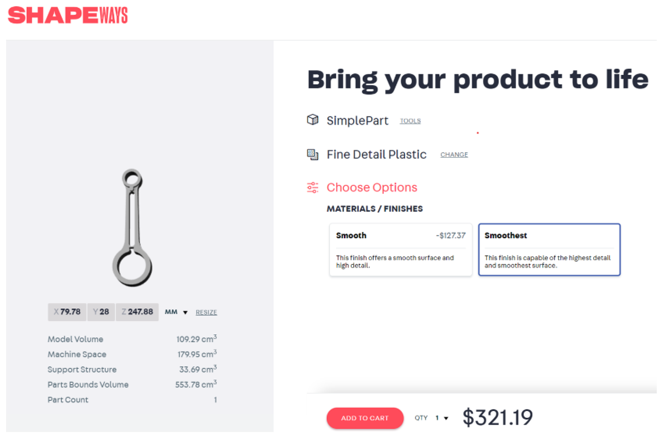
1.2. Comparison with Other AM Platforms
- Automated generation of support structures (not user viewable);
- Repair of STL model (not user viewable);
- Selection of process parameter (not user viewable);
- Quality selection (the user has limited options);
- They are oriented towards enterprise or early-adoption customers that have a finished design and need a prototype;
- Material selection is limited—they typically use medium to high-end materials.
- They are highly flexible—and therefore the setup with host and server is complex.
- The capability of repairing defective STL meshes.
- Control of layer thickness, material, density, and other process parameters is allowed.
- Custom generation of support structures, patterns, infill density for supports is allowed.
- Custom slicers can be imported—for example, newer versions of the slicing engines from Prusa, Cura, Netfabb, or others. This is a feature that is not typically addressed to average users, but it is still useful when special design and production requirements need to be considered.
2. Proposed Methodology
2.1. Scope
2.2. Approach
- Material to be used, including its properties, such as density, cost per weight unit, chamber, or bed temperature;
- Support options, such as support profiles, support on build plate or x-y basis, and parameters per support option;
- Part density;
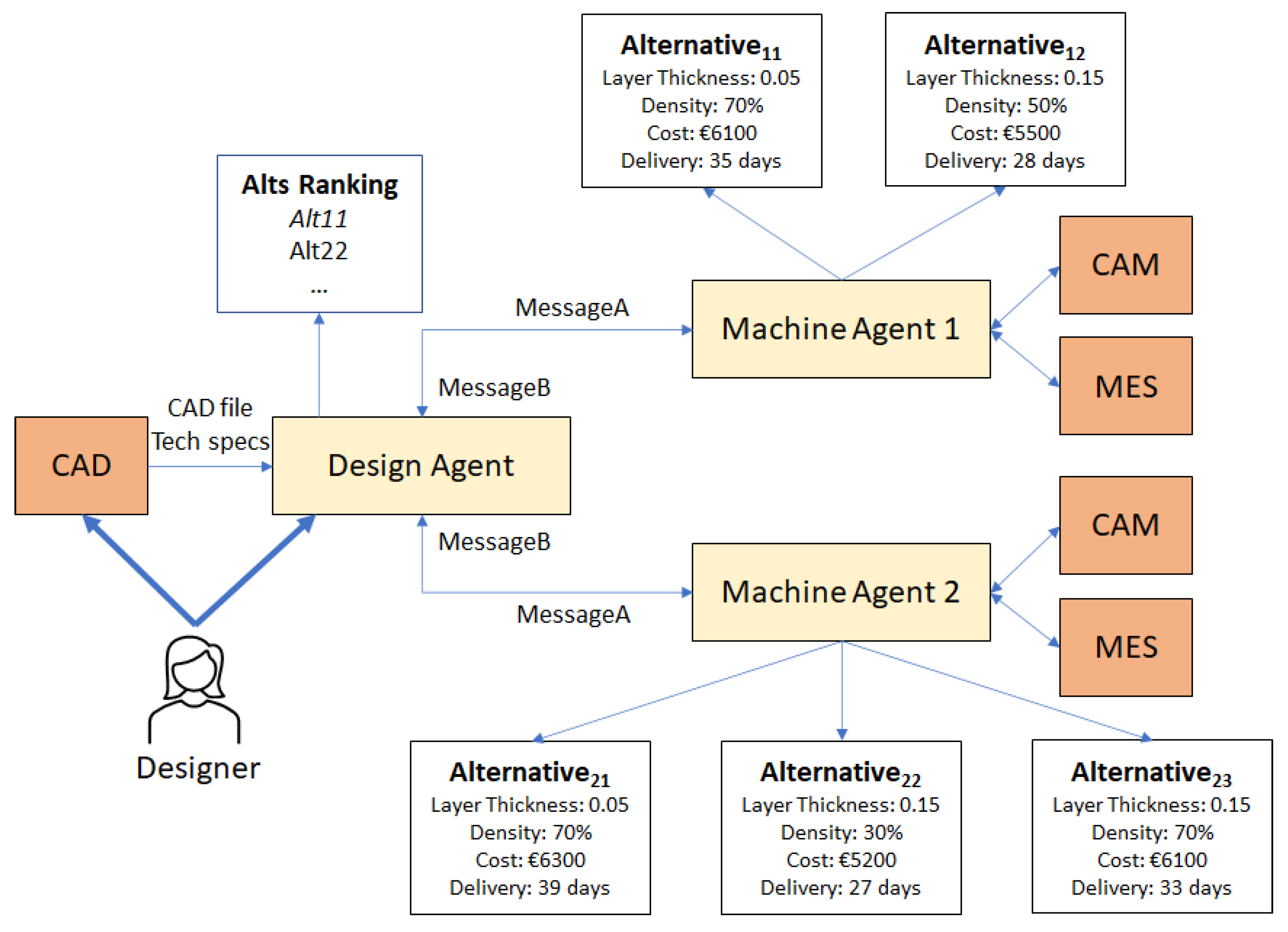
- Once a part is designed, the design engineer (Designer) uses the part geometry analysis tool, which launches the Design Agent (a software instance) who then uploads the CAD file to the cloud or to a remote repository and provides the minimum technical specifications (maximum layer thickness, minimum part density), the basic geometric information (external dimensions and minimum wall thickness), the list of alternative materials that can be used, the number of parts to be produced, the order due date, and decision criteria weights.
- The Design Agent finds all available Machine Agents (software instances) through the platform DF and then sends a message to all suitable Machine Agents, encapsulating all information provided by the Designer, including the link to the repository containing the CAD file, while asking for a bid.
- The Machine Agent selects all CAM process profiles that fulfil all material, density specifications, and support options and calls the CAM software to generate the G-code and simulate the AM process for each one of these profiles.
- The output of the CAM software is then received by the corresponding Machine Agent and the processing time and cost per part are calculated.
- The Machine Agent then requests information regarding the availability of the machine from its MES and estimates the end date for the specific order. This is done by utilising all available idle time slots for producing the number of parts requested by the Design Agent.
- All alternative process configurations are sent by the Machine Agents back to the Design Agent who then estimates their utility by considering the relative importance of all criteria identified by the Designer.
- Then the best alternative is identified by the Design Agent, who sends a message with an order placement request to the corresponding Machine Agent.
- As soon as the Machine Agent confirms the order, the best alternative process configuration with all pertinent information, regarding the process parameters, the service provider and cost, tardiness performance is presented back to the Designer.
- The Machine Agents are then reset so that they can receive new requests from new instances of the same or other Design Agents from the same or another Agents’ Platform.
2.3. Software Design and Implementation
2.4. Cost Function
- s denotes the Machine Agent representing a specific machine of a service provider,
- c denotes the process configuration index,
- Csc is the overall cost for agent s and configuration c,
- Q is the order quantity,
- Asc is the cost rate (€/h) for configuration c of the machine represented by agent s,
- Tsc represents the processing time per piece if configuration c of the machine represented by agent s is selected,
- Msc is the total material cost (€/kg) for building the part using configuration c of the machine represented by agent s,
- Wsc is the overall weight (kg) of the piece if configuration c of the machine represented by agent s is used, including support material,
- Psc represents the set-up and post-processing operations cost per part,
- Ks is the average shipping cost rate from the service provider represented by agent s [€/(km.kg)],
- Ds is the distance between the service provider represented by agent s and the Designer’s location and
- F is the fixed cost per order,
- d(Q,Wsc) is the discount rate applied, based on the overall cost, excluding material costs, which is in turn a function of the part weight and ordered quantity.
3. Test Cases
3.1. Test Case 1
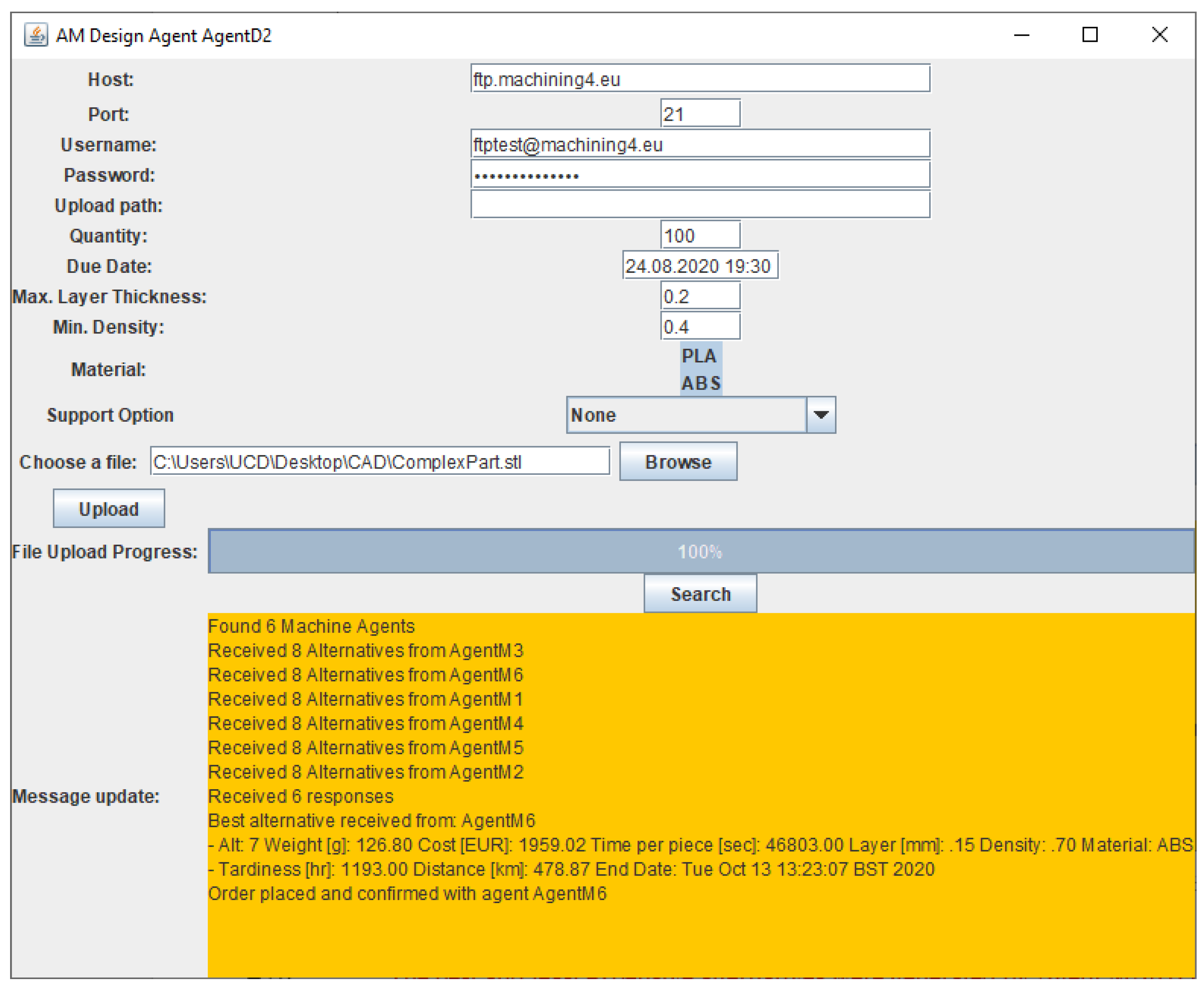
3.2. Test Case 2
3.3. Cases Results Comparison and Simulation Validation
- Time per part: 1–2%,
- Weight per part: 3–4%.
4. Conclusions
Author Contributions
Funding
Conflicts of Interest
Abbreviations
| ABDSS | Agent-Based Decision Support System |
| ABS | Acrylonitrile Butadiene Styrene |
| AHP | Analytic Hierarchy Process |
| AM | Additive Manufacturing |
| AMS | Agent Management System |
| API | Application Programming Interface |
| CAD | Computer-Aided Design |
| CAM | Computer-Aided Manufacturing |
| CM | Conventional Manufacturing |
| CNC | Computer Numerical Control |
| DF | Directory Facilitator |
| DfAM | Design for Additive Manufacturing |
| DSS | Decision Support System |
| FDM | Fused Deposition Modelling |
| GUI | Graphical User Interface |
| IoT | Internet of Things |
| JADE | Java Agent Development Framework |
| MADM | Multi-Attribute Decision-Making |
| MAHP | Multiplicative Analytic Hierarchy Process |
| MAS | Multi-Agent Systems |
| MES | Manufacturing Execution System |
| OEM | Original Equipment Manufacturer |
| PBF | Powder Bed Fusion |
| PLA | Polylactic Acid |
| RPA | Robotic process automation |
| SMART | Simple Multiple Attribute Rating Technique |
| SME | Small and Medium Enterprise |
References
- ISO International; ASTM International. ISO ASTM 52910: 2018 Additive Manufacturing—Design—Requirements, Guidelines and Recommendations; ISO–International Organization for Standardization: Geneva, Switzerland, 2018. [Google Scholar]
- Bikas, H.; Stavropoulos, P.; Chryssolouris, G. Additive manufacturing methods and modeling approaches: A critical review. Int. J. Adv. Manuf. Technol. 2016, 83, 389–405. [Google Scholar] [CrossRef]
- Thompson, M.K.; Moroni, G.; Vaneker, T.; Fadel, G.; Campbell, R.I.; Gibson, I.; Bernard, A.; Schulz, J.; Graf, P.; Ahuja, B.; et al. Design for additive manufacturing: Trends, opportunities, considerations, and constraints. CIRP Ann. 2016, 65, 737–760. [Google Scholar] [CrossRef]
- Mellor, S.; Hao, L.; Zhang, D. Additive manufacturing: A framework for implementation. Int. J. Prod. Econ. 2014, 149, 194–201. [Google Scholar] [CrossRef]
- Brøtan, V.; Berg, O.Å.; Sørby, K. Additive manufacturing for enhanced performance of molds. Procedia CIRP 2016, 54, 186–190. [Google Scholar] [CrossRef]
- Khajavi, S.H.; Partanen, J.; Holmström, J. Additive manufacturing in the spare parts supply chain. Comput. Ind. 2014, 65, 50–63. [Google Scholar] [CrossRef]
- Li, Y.; Jia, G.; Cheng, Y.; Hu, Y. Additive manufacturing technology in spare parts supply chain: A comparative study. Int. J. Prod. Res. 2017, 55, 1498–1515. [Google Scholar] [CrossRef]
- Hasan, S.; Rennie, A.E.W. The application of rapid manufacturing technologies in the spare parts industry. In Proceedings of the 19th Annual International Solid Freeform Fabrication Symposium, Austin, TX, USA, 4–8 August 2008; pp. 584–590. [Google Scholar]
- Liu, P.; Huang, S.H.; Mokasdar, A.; Zhou, H.; Hou, L. The impact of additive manufacturing in the aircraft spare parts supply chain: Supply chain operation reference (scor) model based analysis. Prod. Plan. Control 2014, 25, 1169–1181. [Google Scholar] [CrossRef]
- Beiderbeck, D.; Deradjat, D.; Minshall, T. The Impact of Additive Manufacturing Technologies on Industrial Spare Parts Strategies; University of Cambridge: Cambridge, UK, 2018. [Google Scholar] [CrossRef]
- Gardan, N.; Schneider, A. Topological optimization of internal patterns and support in additive manufacturing. J. Manuf. Syst. 2015, 37, 417–425. [Google Scholar] [CrossRef]
- Hague, R.; Reeves, P. Additive Manufacturing and 3D Printing; Wohlers Associates, Inc.: Fort Collins, CO, USA, 2013; ISBN 978-0-9913332-4-0. [Google Scholar]
- Zadpoor, A.A.; Malda, J. Additive manufacturing of biomaterials, tissues, and organs. Ann. Biomed. Eng. 2017, 45, 1–11. [Google Scholar] [CrossRef] [PubMed]
- Fayazfar, H.; Salarian, M.; Rogalsky, A.; Sarker, D.; Russo, P.; Paserin, V.; Toyserkani, E. A critical review of powder-based additive manufacturing of ferrous alloys: Process parameters, microstructure and mechanical properties. Mater. Des. 2018, 144, 98–128. [Google Scholar] [CrossRef]
- Thomas, D.S.; Gilbert, S.W. Costs and Cost Effectiveness of Additive Manufacturing; NIST Special Publication: Gaithersburg, MD, USA, 2014. [Google Scholar]
- Patalas-Maliszewska, J.; Topczak, M.; Kłos, S. The Level of the Additive Manufacturing Technology Use in Polish Metal and Automotive Manufacturing Enterprises. Appl. Sci. 2020, 10, 735. [Google Scholar] [CrossRef]
- Huang, Y.; Leu, M.C.; Mazumder, J.; Donmez, A. Additive manufacturing: Current state, future potential, gaps and needs, and recommendations. J. Manuf. Sci. Eng. 2015, 137, 014001. [Google Scholar] [CrossRef]
- Slic3r Slic3r-Open Source 3D Printing Toolbox. Available online: https://slic3r.org/ (accessed on 12 October 2019).
- Koomen, B.; Hoogeboom, M.; Schellens, V. PLM Implementation Success Rate in SME. An Empirical Study of Implementation Projects, Preliminary Findings. In Proceedings of the IFIP Advances in Information and Communication Technology, Kyiv, Ukraine, 9–10 October 2019; Volume 565, pp. 47–57. [Google Scholar]
- Sokolova, M.V.; Fernández-Caballero, A. Modeling and implementing an agent-based environmental health impact decision support system. Expert Syst. Appl. 2009, 36, 2603–2614. [Google Scholar] [CrossRef]
- Legien, G.; Sniezynski, B.; Wilk-Kołodziejczyk, D.; Kluska-Nawarecka, S.; Nawarecki, E.; Jaśkowiec, K. Agent-based decision support system for technology recommendation. Procedia Comput. Sci. 2017, 108, 897–906. [Google Scholar] [CrossRef]
- Alter, S. Taxonomy of Decision Support Systems. Sloan Manag. Rev. 1977, 19, 39–56. [Google Scholar]
- DeSanctis, G.; Gallupe, R.B. Decision Support Systems: Concepts and Resources for Managers; Greenwood Publishing Group: Santa Barbara, CA, USA, 1987; Volume 33, ISBN 156720497X. [Google Scholar]
- Park, H.S.; Tran, N.H. A decision support system for selecting additive manufacturing technologies. In Proceedings of the 2017 International Conference on Information System and Data Mining (ICISDM ‘17), New York, NY, USA, 1–3 April 2017; pp. 151–155. [Google Scholar]
- Kretzschmar, N.; Ituarte, I.F.; Partanen, J. A decision support system for the validation of metal powder bed-based additive manufacturing applications. Int. J. Adv. Manuf. Technol. 2018, 96, 3679–3690. [Google Scholar] [CrossRef]
- Ghazy, M.M. Development of an Additive Manufacturing Decision Support System (AMDSS). Ph.D. Thesis, Newcastle University, Newcastle, UK, 2012. [Google Scholar]
- Borille, A.V.; Gomes, J.D.O. Selection of additive manufacturing technologies using decision methods. In Rapid Prototyping Technology—Principles and Functional Requirements; IntechOpen: London, UK, 2011. [Google Scholar]
- Braglia, M.; Petroni, A. A management-support technique for the selection of rapid prototyping technologies. J. Ind. Technol. 1999, 15, 1–6. [Google Scholar] [CrossRef]
- Byun, H.S.; Lee, K.H. A decision support system for the selection of a rapid prototyping process using the modified TOPSIS method. Int. J. Adv. Manuf. Technol. 2005, 26, 1338–1347. [Google Scholar] [CrossRef]
- Zhang, Y.; Xu, Y.; Bernard, A. A new decision support method for the selection of RP process: Knowledge value measuring. Int. J. Comput. Integr. Manuf. 2014, 27, 747–758. [Google Scholar] [CrossRef]
- Meisel, N.A.; Williams, C.B.; Ellis, K.P.; Taylor, D. Decision support for additive manufacturing deployment in remote or austere environments. J. Manuf. Technol. Manag. 2016, 27, 898–914. [Google Scholar] [CrossRef]
- Bikas, H.; Koutsoukos, S.; Stavropoulos, P. A decision support method for evaluation and process selection of additive manufacturing. Procedia CIRP 2019, 81, 1107–1112. [Google Scholar] [CrossRef]
- Rao, R.V.; Padmanabhan, K.K. Rapid prototyping process selection using graph theory and matrix approach. J. Mater. Process. Technol. 2007, 194, 81–88. [Google Scholar] [CrossRef]
- Watson, J.K.; Taminger, K.M.B. A decision-support model for selecting additive manufacturing versus subtractive manufacturing based on energy consumption. J. Clean. Prod. 2018, 176, 1316–1322. [Google Scholar] [CrossRef]
- Wang, Y.; Zhong, R.Y.; Xu, X. A decision support system for additive manufacturing process selection using a hybrid multiple criteria decision-making method. Rapid Prototyp. J. 2018, 24, 1544–1553. [Google Scholar] [CrossRef]
- Wang, Y.; Blache, R.; Xu, X. Selection of additive manufacturing processes. Rapid Prototyp. J. 2017, 23, 434–447. [Google Scholar] [CrossRef]
- Zhang, Y.; Bernard, A.; Harik, R.; Karunakaran, K.P. Build orientation optimization for multi-part production in additive manufacturing. J. Intell. Manuf. 2017, 28, 1393–1407. [Google Scholar] [CrossRef]
- Monostori, L.; Váncza, J.; Kumara, S.R.T. Agent-based systems for manufacturing. Cirp Ann.-Manuf. Technol. 2006, 55, 697–720. [Google Scholar] [CrossRef]
- García-Magariño, I. ABSTUR: An agent-based Simulator for Tourist Urban Routes. Expert Syst. Appl. 2015, 42, 5287–5302. [Google Scholar] [CrossRef]
- Ricci, A.; Santi, A. Agent-Oriented Computing: Agents as a Paradigm for Computer Programming and Software Development. In Proceedings of the Future Computing 2011: The Third International Conference on Future Computational Technologies and Application, Rome, Italy, 25–30 September 2011; pp. 42–51. [Google Scholar]
- Jin, Y.; Lu, S.C.Y. An agent-supported approach to collaborative design. CIRP Ann. 1998, 47, 107–110. [Google Scholar] [CrossRef]
- Amara, H.; Dépincé, P.; Hascoët, J.Y. A human-centered architecture for process planning. CIRP J. Manuf. Syst. 2004, 33, 363–372. [Google Scholar]
- Maropoulos, P.G.; McKay, K.R.; Bramall, D.G. Resource-aware aggregate planning for the distributed manufacturing enterprise. CIRP Ann. 2002, 51, 363–366. [Google Scholar] [CrossRef]
- Zweben, M.; Fox, M.S.; Francisco, S.; Kaufmann, M.; Arbor, A. Intelligent Scheduling; Morgan Kaufmann Publishers Inc.: Burlington, MA, USA, 1994; Volume 6, ISBN 1558602607. [Google Scholar]
- Monostori, L.; Prohaszka, J. A Step towards intelligent manufacturing: Modelling and monitoring of manufacturing processes through artificial neural networks. CIRP Ann. 1993, 42, 485–488. [Google Scholar] [CrossRef]
- Balakrishnan, A.; Kumara, S.R.T.; Sundaresan, S. Manufacturing in the digital age: Exploiting information technologies for product realization. Inf. Syst. Front. 1999, 1, 25–50. [Google Scholar] [CrossRef]
- Fox, M.S.; Barbuceanu, M.; Teigen, R. Agent-oriented supply-chain management. Int. J. Flex. Manuf. Syst. 2000, 12, 165–188. [Google Scholar] [CrossRef]
- Bussmann, S.; Sieverding, J. Holonic control of an engine assembly plant an industrial evaluation. In Proceedings of the IEEE International Conference on Systems, Man and Cybernetics, Tucson, AZ, USA, 7–10 October 2001; Volume 1, pp. 169–174. [Google Scholar]
- Niemann, J.; Ilie Zudor, E.; Monostori, L.; Westkämper, E. Agent-based product life cycle data support. Manuf. Model. Manag. Control 2005, 105–110. [Google Scholar]
- Dhokia, V.; Essink, W.P.; Flynn, J.M. A generative multi-agent design methodology for additively manufactured parts inspired by termite nest building. CIRP Ann. 2017, 66, 153–156. [Google Scholar] [CrossRef]
- Allen, R.D.; Harding, J.A.; Newman, S.T. The application of STEP-NC using agent-based process planning. Int. J. Prod. Res. 2005, 43, 655–670. [Google Scholar] [CrossRef]
- Mourad, M.; Nassehi, A.; Newman, S.; Schaefer, D. C-MARS-ABM: A Deployment Approach for Cloud Manufacturing. In Proceedings of the Advances in Transdisciplinary Engineering; IOS Press BV: Amsterdam, The Netherlands, 2017; Volume 6, pp. 213–218. [Google Scholar]
- Dong, C.; Yuan, Y.; Lei, W. Additive manufacturing cloud based on multi agent systems and rule inference. In Proceedings of the 2016 IEEE Information Technology, Networking, Electronic and Automation Control Conference, Chongqing, China, 22–26 May 2016; pp. 45–50. [Google Scholar]
- Wang, L.; Yao, Y.; Yang, X.; Chen, D. Multi agent based additive manufacturing cloud platform. In Proceedings of the 2016 IEEE International Conference on Cloud Computing and Big Data Analysis (ICCCBDA), Chengdu, China, 5–7 July 2016; pp. 290–295. [Google Scholar] [CrossRef]
- Mourtzis, D.; Vlachou, E.; Xanthopoulos, N.; Givehchi, M.; Wang, L. Cloud-based adaptive process planning considering availability and capabilities of machine tools. J. Manuf. Syst. 2016, 39, 1–8. [Google Scholar] [CrossRef]
- Holligan, C.; Hargaden, V.; Papakostas, N. Product lifecycle management and digital manufacturing technologies in the era of cloud computing. In Proceedings of the 2017 International Conference on Engineering, Technology and Innovation: Engineering, Technology and Innovation Management Beyond 2020: New Challenges, New Approaches, Funchal, Portugal, 27–29 June 2017; ICE/ITMC 2017-Proceedings. 2018; Volume 2018-Janua, pp. 909–918. [Google Scholar]
- Papakostas, N.; Newell, A.; Hargaden, V. A novel paradigm for managing the product development process utilising blockchain technology principles. CIRP Ann. 2019, 68, 137–140. [Google Scholar] [CrossRef]
- Shubham, P.; Sikidar, A.; Chand, T. The influence of layer thickness on mechanical properties of the 3D printed ABS polymer by fused deposition modeling. In Key Engineering Materials 2016; Trans Tech Publications Ltd.: Lausanne, Switzerland, 2016; Volume 706, pp. 63–67. [Google Scholar]
- Pérez, M.; Medina-Sánchez, G.; García-Collado, A.; Gupta, M.; Carou, D. Surface quality enhancement of fused deposition modeling (FDM) printed samples based on the selection of critical printing parameters. Materials. 2018, 11, 1382. [Google Scholar] [CrossRef]
- Terzi, S.; Bouras, A.; Dutta, D.; Garetti, M.; Kiritsis, D. Product lifecycle management-From its history to its new role. Int. J. Prod. Lifecycle Manag. 2010, 4, 360–389. [Google Scholar] [CrossRef]
- Bellifemine, F.; Bergenti, F.; Caire, G.; Poggi, A. Jade—A Java Agent Development Framework. In Multi-Agent Programming; Springer: Boston, MA, USA, 2005; pp. 125–147. [Google Scholar]
- Costabile, G.; Fera, M.; Fruggiero, F.; Lambiase, A.; Pham, D. Cost models of additive manufacturing: A literature review. Int. J. Ind. Eng. Comput. 2016, 8, 263–282. [Google Scholar] [CrossRef]
- Chryssolouris, G. Manufacturing Systems: Theory and Practice, 2nd ed.; Springer: New York, NY, USA, 2006. [Google Scholar]


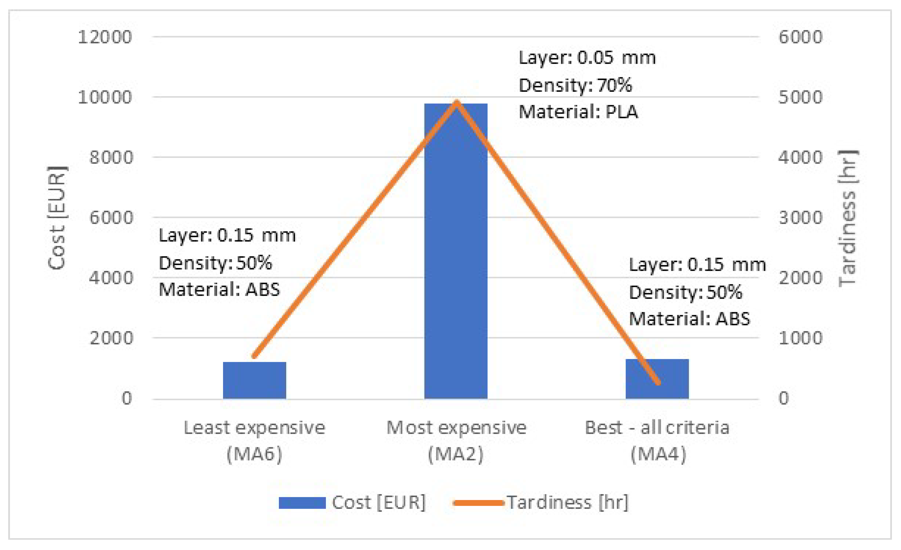
| Criterion | Weight/Performance—Case 1 | Weight/Performance—Case 2 |
|---|---|---|
| Layer thickness | 40%/0.15 mm [ABS] | 20%/0.15 mm [ABS] |
| Density | 0%/50% | 50%/70% |
| Tardiness | 30%/266 h | 20%/1193 h |
| Cost | 30%/1333.03 EUR | 10%/1959.02 EUR |
| Information | Test Case 1 (MA4) | Test Case 2 (MA1) |
|---|---|---|
| Time (simulation) | 11 h 34 min (41,652 s) | 15 h 19 min (55,114 s) |
| Time (actual) | 11 h 29 min (41,340 s) | 15 h 11 min (54,660 s) |
| Weight (simulation) | 73.30 g | 102.90 g |
| Weight (actual) | 75.55 g | 99.28 g |
© 2020 by the authors. Licensee MDPI, Basel, Switzerland. This article is an open access article distributed under the terms and conditions of the Creative Commons Attribution (CC BY) license (http://creativecommons.org/licenses/by/4.0/).
Share and Cite
Papakostas, N.; Newell, A.; George, A. An Agent-Based Decision Support Platform for Additive Manufacturing Applications. Appl. Sci. 2020, 10, 4953. https://doi.org/10.3390/app10144953
Papakostas N, Newell A, George A. An Agent-Based Decision Support Platform for Additive Manufacturing Applications. Applied Sciences. 2020; 10(14):4953. https://doi.org/10.3390/app10144953
Chicago/Turabian StylePapakostas, Nikolaos, Anthony Newell, and Abraham George. 2020. "An Agent-Based Decision Support Platform for Additive Manufacturing Applications" Applied Sciences 10, no. 14: 4953. https://doi.org/10.3390/app10144953
APA StylePapakostas, N., Newell, A., & George, A. (2020). An Agent-Based Decision Support Platform for Additive Manufacturing Applications. Applied Sciences, 10(14), 4953. https://doi.org/10.3390/app10144953